1
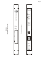
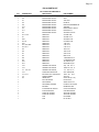
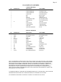
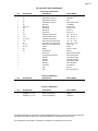
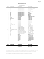
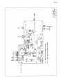
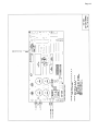
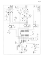
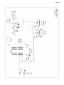
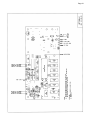
Page 2 Date: The date information encoded into the "user bits" of the SMPTE time code is typically set to include Month-Day-Year information. Turning “ON” the "DOY" DIP switch (switch #5 on the ES-101 logic board) reformats the data to contain Day of Year (001-366) instead of MonthDay-Year. ESE Time Code: The most efficient and cost-effective method for time code distribution in a Master Clock/Remote Clock System employs the ESE Time Code output. ESE Time Code is capable of driving up to 100 remote displays at a distance of up to 4000 feet. Connections (between the ES-102 ESE Time Code Output and any ESE Time Code Reader) can be made using twisted pair wire or coax cable such as RG-58 or RG-59. The accuracy is 17mS of UTC and the time code is accessible on two separate BNC connectors (TC89 & TC90). TC89 is an older version of ESE Time Code and should be used to drive older ESE Time Code Readers (non-”A” versions). TC90 contains “Date” information as well as time data and should be used if “Date” is to be displayed on the Reader. RS-232C: RS-232C ASCII Time Code is used to interface with a PC or other computer system. The ASCII transmission contains date and time data and is transmitted once per second. The data is accessible on the DB-9 connector. Windows and DOS software included with the unit enables the ES-102 to continuously update a computer’s clock. (Software is also available from the ESE Web-Site at http://www.ESE-WEB.com.) GPS “Lock”: Access to a TTL output of GPS "Lock" information is accessible on the DB-9 connector. When locked the signal goes to a logic “1”. 1PPS: The most accurate time information available from the ES-102 is that provided by the 1PPS Output (one pulse per second). Two (2) outputs are provided: a 20% duty signal specified as being within 500ns of UTC, and a 50% duty signal which is within 1mS of UTC. The 20% duty signal is obtained directly from the receiver. The 50% duty signal is regenerated by the timekeeping microprocessor; this signal is isolated from dropouts due to signal loss and should be used for long-term timekeeping purposes. Both signals are positive edge true. The 1PPS can be used for synchronization purposes in a variety of applications. One such application allows the 1PPS to drive an Impulse Driver (ES-165 or ES-162A) which, in turn, can drive "Analog" Impulse Clocks (ES-168 or ES-162S). Battery The ES-102 has a lithium coin cell battery that maintains certain receiver configuration settings during power outages, storage or shipment. The battery is capable of maintaining these settings for up to four years. All outputs, however, are suspended during a power outage. If continuous outputs during power outages are required, a UPS (Uninterruptable Power Supply) is suggested. Option “BBU” is available and is capable of maintaining power to all outputs during a power outage for up to four hours. Antenna An "active" GPS Antenna (1.575 GHz) with 16’ 5” cable is supplied with the ES-102 and connects to the unit via a TNC connector. ESE has conducted a series of tests with the purpose of determining a maximum cable length (with or without amplification). A summary of the tests and the alternatives are discussed on page 8. Proper installation of the antenna module is imperative for proper operation and continued life of the antenna and clock. See page 7. Enclosure The ES-102 is housed in a rack-mount enclosure that measures 1.75" high x 19" wide x 9.5" deep (plus connectors). The ruggedized enclosure is constructed of etched and clear anodized aluminum. SETUP FEATURES Several features of the ES-102 are factory set according to information supplied by the end user or according to factory standards. All Setup Features are selected via DIP switches except "Time Zone", "Time Delay/Advance" and "Cable Delay". All Setup Features are discussed below. Time Zone: The ES-102 receives GPS time and date information which has been encoded and set to UTC (Universal Coordinated Time/Greenwich Mean Time). The unit must be set at the factory to decode and output time for the end-user's time zone. Or, by using the software supplied with the ES-102, the time-zone can be changed "in the field". This is accomplished by connecting the RS-232C input to a computer serial port and running the ESEGPS (Windows) or GPSINI.EXE (DOS) programs. Running GPSINI.EXE without command line switches will print the instructions on screen. Run the GPSINI.EXE program again using the appropriate command line parameters. Please connect ONLY the 2 data lines & the ground line to the computer: the DB-9 connector also provides access