1
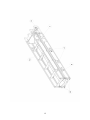
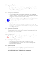
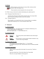
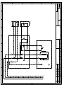
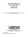
Operating Manual Conveyor Belt LIBELT 600 This operating manual is a critical component to the conveyor belt. It must be available to the operator at all times. Maschinenbau GmbH Lanzstraße 4 - D-88410 Bad Wurzach Telefon +49 (0) 75 64/3 07-0 - Fax + 49 (0) 75 64/3 07-5 00 [email protected] - www.lissmac.com Revised: 2010/02 Translation of the original operating manual 1 Preface to the Operating Manual This operating manual should make it easier to acquaint yourself with the machine and its features. The operating manual contains important precautions on operating the machine safely, correctly and efficiently. Following the instructions helps prevent accidents, unnecessary repair costs and down time, which extends the machine’s reliability and durability. The operating manual shall be used in compliance with any national laws concerning accident prevention and environmental protection. The operating manual must constantly be in the vicinity of the machine. Operation, including setting-up, troubleshooting, disposal of waste products, product care, application of lubrication and auxiliary products. Servicing (maintenance, inspection, repair) and/or Transport In addition to the operating manual and to comply with all national and local regulations concerning accident prevention, the technical instructions below must also be recognized to ensure safe and correct operation. Table of Contents 1. General Safety Requitements 2. Description of machine 3. Commissioning 4. Transport 5. Operation 6. Maintenance 7. Malfunctions 8. Periodic control check 9. Accessories 10. Guarantee 2 1. General Safety Precautions 1.1 Warning Labels and Symbols used in this Manual Danger! Caution ! Not following the instructions may result in serious injuries or even death. Not following the instructions may, under certain conditions, result in injuries. Note Not following the instructions may result in damage to the machine or other equipment. 1.2 General Safe Operating Procedures 1.2.1 This conveyor belt is built according to the latest in technology and recognized safety standards. Nevertheless, bodily injury and death to the operator or third persons or damage to surrounding objects - like the machine and other equipment - is possible. 1.2.2 Use the conveyor belt only in good working condition and follow all procedures concerning correct and safe operation, as outlined in the manual! This especially includes malfunctions that can jeopardize safety! Any troubles must be eliminated immediately! 1.2.3 The conveyor belt is designed to carry bulk products up to a maximum size of 120 mm in diameter. Materials such as sand, gravel, building debris, soil and other natural or agricultural products, like beets, potatoes, corn, etc. can be transported (belt is not suited for food stuffs). Transporting people, materials over 40 °C, pointy or sharp objects and acidic substances is not allowed. Any other type of use other than those listed above, is not recommended. The manufacturer/distributor is not liable for damages caused by improper use of the machine. Correct operation also requires due observance of the operating manual as well as inspection and maintenance procedures. 3 1.3 Organizational Measures 1.3.1 Always keep the operating manual in the vicinity of the machine! 1.3.2 Please also observe any supplements to this manual regarding legal or generally valid regulations for prevention of accidents or referring to environmental control. Such obligations may also include instructions regarding work with hazardous material, wearing adequate protective clothing or the observance of road traffic regulations. 1.3.3 Any personnel who work on the conveyor belt must have already read the operating manual. - especially this chapter on safety precautions - prior to beginning. Learning on the job is too late! This especially applies to personnel who occasionally work on the machine (e.g. setup and maintenance crews). 1.3.4 Carry out regular spot checks to ensure that personnel are performing their jobs in a safe and conscientious manner and that they are adhering to the instructions in the operating manual! 1.3.5 Use personal protective equipment, whenever necessary or required by regulation. 1.3.6 Pay attention to all safety warning labels located on the machine! 1.3.7 Keep all safety and danger warning labels in/on the machine completely legible. 1.3.8 Stop the machine and notify the parties in charge whenever safety-related changes to the machine or the way in which it operates are going to be made! 1.3.9 Make no alterations and do not add componentry or rebuild the machine without permission from the manufacturer! 1.3.10 Use only original spare parts from the manufacturer 1.3.11 Perform all scheduled inspections as needed, or use the scheduled intervals outlined in the operating manual! 1.3.12 In order to carry through with maintenance procedures, the machine must be set up according to the type of work it will be doing. 1.3.13 Operating temperatures for the conveyor belt must be between –10 and +40 °C. 4 1.4 Qualifications for Selecting Personnel; Fundamental Responsibilities 1.4.1 Only personnel of proven reliability is allowed to operate the conveyor belt. Observe legal minimum age requirements. 1.4.2 All personnel must have received full training on operating the conveyor belt. Clearly define responsibilities regarding operation, setup, maintenance, and repair. 1.4.3 Ensure that the conveyor belt is handled only by persons instructed to do so. 1.4.4 Define machine operator's responsibility - also in respect to road traffic regulations - and his ability to object to instructions not in compliance with the safety regulations! 1.4.5 Apprentices, new employees, or personnel being trained must be accompanied at all times by an experienced operator while working on the conveyor belt. 1.4.6 Any work at the electrical equipment of the machine must be carried out by a qualified electrician only or a trained person under the supervision of a qualified electrician, in accordance with the rules and standards for electronics. 1.5 Safety Precautions for Specific Operational Phases 1.5.1 Normal Operation 1.5.1.1 Refrain from all working methods that pose a safety risk. 1.5.1.2 Take steps to ensure the conveyor belt is in a safe, operable manner! 1.5.1.3 The conveyor belt must be examined for external damage at least once per shift! Report any changes (including operational behavior) to the appropriate personnel at once! If necessary, immediately stop and secure the machine. 1.5.1.4 Immediately stop and secure the conveyor belt when malfunctioning! Promptly fix the problem! 1.5.1.5 Before turning on and running the conveyor belt, ensure that no one is in a position to be injured! 5 1.5.2 Special Work Incurring during Utilization of the Conveyor Belt, Maintenance Procedures, Trouble-Shooting; Waste Disposal 1.5.2.1 Follow the instructions in the operating manual when adjusting, maintaining and inspecting componentry and performing scheduled work. This includes the replacement of parts! Only qualified personnel are allowed to perform these activities. 1.5.2.2 Notify operations personnel of any maintenance or additional work prior to performing it! Appoint a supervisor! 1.5.2.3 When the conveyor belt is completely turned off for maintenance or repair work, it must be safeguarded against an unexpected restart. 1.5.2.4 Cover up/close all openings in the machine before cleaning it with water or other cleaning agents. Keeping water/vapor/cleaning agents from penetrating the machine avoids safety hazards and equipment damage. Electric motors, switches and outlets are especially vulnerable. 1.5.2.5 Completely remove all covers/tape after cleaning! 1.5.2.6 Tighten down any loose screws after performing maintenance or repair work! 1.5.2.7 If the conveyor belt needs to be dismantled for setting up, maintenance or repairs, it must be reassembled afterwards and immediately tested for its safety features in order to ensure safe operation! 1.5.2.8 Ensure safe and environmentally friendly practices when disposing of lubricants and auxiliary supplies (e.g. parts replacement)! 6 1.6 Precautions for Special Types of Danger 1.6.1 Electric Energy 1.6.1.1 Use only original fuses with the electrical current for which they were designed! Immediately turn off the conveyor belt when encountering electrical problems! 1.6.1.2 Work on the conveyor’s electrical components may only be performed by an electronics specialist, or trained personnel, who must be accompanied by such a specialist. Work must be in accordance with the regulations pertaining to electrical maintenance. 1.6.1.3 Proceed with maintenance or repair work only after all electrical current to the machine has been turned off. The voltage can damage the capacitors. 1.6.1.4 Regularly inspect/check all electrical equipment. Any defects like loose connections (eg. damages cables) must be repaired without delay. 1.6.1.5 Only run the conveyor belt on circuits protected by an FI safety switch 1.6.2 Dust 1.6.2.1 Observe all national regulations and standards when working in small spaces! 1.6.3 Noise Level 1.6.3.1 Permanent sound level is found below 70 dB(A)! 1.7 Transport 1.7.1 When transporting the conveyor belt, follow proper loading procedures and use only power lifting equipment with adequate carrying capacity! 1.7.2 Have an experienced coordinator direct the loading process! 1.7.3 Lift the conveyor only according to the instructions in this manual (striking points for loading procedures)! 1.7.4 Use appropriate transport vehicle with adequate carrying capacity. 1.7.5 Secure load in a dependable manner. Use the striking points! 1.7.6 Turn off the power even when moving the conveyor belt only a small distance! Before restarting, ensure the machine is duly reconnected. 1.7.7 Follow the instructions when restarting! 7 2. Description of Machine Componentry 2.1 Overview of Components Key 1 – Steel frame – motor Key 1.1 – Steel frame – deflexion roller Key 2 – Holder for support legs or wheels Key 3 – Conveyor belt Key 4 – Recess for fork lifter Key 5 – Transport grips Key 6 – Fastening elements for conveyor belt Key 7 - Motor Key 8 – Connector Key 9 – Socket coupler for current transmission (pull-out type) Key 10 - Switch Key 11 – Emergency-stop switch Key 12 – Steel wire rope: safety device for belt Key 13 – binding screws Key 13.1 – return roller 2.2 Accessories Key 14 – Feed hopper Key 15 – Support legs Key 16 – Set of wheels 2.3 Protective gear Key 10 - Switch Key 11 – Emergency-stop switch 8 9 2.4 Technical Data Length Width Height Weight Material Belt material Belt width/height 2 motors Conveying speed Max. loading capacity Max. inclination LIBELT 600 Work position Transport position 5640 mm (folded) 2950 mm 555 mm 260 mm 490 mm 166 kg Galvanized steel PVC textile belt / standard (rubber belt / special version) with studs 20 mm 400/3-PVC 230V, 50 Hz, 1,3 kW, 8,7 A 25 m/min. 50 kg/m Max. 300 kg total 40° 3. Commissioning 3.1 Fundamentals Danger ! - Do not allow persons to be transported Note - The conveyor belt is designed to carry bulk products only up to a maximum size of 120 mm. Sand, gravel, building debris, soil, agricultural products like beets, potatoes, corn etc. can be carried. The conveyor belt is not suited for food stuffs and should not be used for transporting material over 40°C, especially liquids. Do not transport product with sharp edges (eg. broken glass)! - Always start the conveyor belts without load, especially in cold temperatures. If possible, let the belts run empty before turning off. 10 Caution ! - There may not be connected 2 conveyor belts LIBELT 600. You may connect the LIBELT 600 with one LIBELT 300 or one LIBELT 400 in a chain. Note - Each chain of conveyor belts (max. 2 conveyor belts!) must have its own power supply, secured by a 16 A fuse. There must not be any additional power consumer connected to this source of energy. Danger! -Always turn off the conveyor belt and disconnect the cable when placing another conveyor unit behind. Danger ! - After setting up, ensure that every belt is secure and will not skid or tip over under a load. Danger ! - Take steps to ensure that no people or surrounding objects can be harmed by products falling off the belt. This is especially the case when the belts are in raised position. Danger ! - The conveyor belts must not lie in water or be used in the water. Note The conveyor belts should not be used in heavy rainstorms. Protect the belts from moisture. 3.2 Setting up the Conveyor Belts Danger ! - Ensure secure footing of each conveyor belt, fasten with ties, if necessary. You need to be aware of the fact that the load can transfer unevenly, or wedge in between the belts. Danger ! -.Because product will fall off from time to time, it is necessary to protect people and surrounding objects from potential collisions. This is especially the case when the conveyor belt is in a raised position. Contact your safety supervisor if an accident happens 3.2.1 Set up of the Conveyor Belts - 2 persons hold the transport handles (key 5) of the steel frame (key 1.1) Open steel frame (key 1.1) Connect keys 1.1 and 1 of the frame with the binding screws (key 13) Open steel wire rope safety device (key 12) – pull through the steel frame and close again 11 12 3.2.2 Appropriate Prop Up - To set up a proper substructure to the conveyor belt, two tubes (key 2) have been inserted into the steel rails (key 1 + 1.1) at their ends. Connecting rods may be inserted into these tubes. This allows quick and safe positioning of the prop-up fixture. 3.2.3 Overlapping in a straight line - If the overlapping belts are running in a straight line, the overlapping length can be short. If the conveyors do not have good footing, provide a substructure and secure them so they do not slide. Caution! The transport bands can be damaged when back-rolling load comes between two belts. In this case please use a feed hopper. (Accessory key 14) 3.2.4 Overlapping in an angle - In this case the feed hopper should be used (Accessory, key 14). The feed hopper allows a clean transfer from belt to belt and prevents product from falling off the side. 3.2.5 Loading the Conveyor Belts - Gently place the product on the belt. Do not throw heavy objects on the belt or let them fall from a great height! 3.3 Electrical Installation Danger ! All electrical parts must be inspected prior to each operation.If any alterations are detected, the parts have to be exchanged and marked accordingly. The damaged parts must be repaired or destroyed immediately by an authorized person. 3.3.1 Connecting the Conveyor Belts - Insert the supply cable into the left side of the first belt (key 8). If multiple belts are being connected, then use the connecting cable (key 9) to transmit the current. 3.3.2 Safety Precautions - Make sure that the outlets and plugs are clean and fully connected. - Use only cable which is compatible with 16 A. - Do not connect any further consumers to this power source. 13 3.4 Starting Danger ! - Before powering up the chain of conveyor belts, make sure that nobody is within the danger zone. - There should be no bulk material on the conveyor belts. 3.4.1 Each conveyor belt must be started individually by the switch (key 10). 3.4.2 Emergency Stop Switch (Key 11) -Activating the „Emergency Stop“ button stops the chain of conveyor belts. After the trouble-shooting, the belts need to be restarted. 3.4.2 Turning off (Key 10) When possible, you should let the chain of conveyor belts run completely empty before shutting off, so it can be restarted without load. 4. Transport 4.1 Transport position - The feed hoper (key 14), support legs (key 15) and pair of wheels (key 16) must be disassembled for transporting. Both steel frames (key 1 + 1.1) are folded (see 5.1) 4.2 Transport by Truck Danger ! - The conveyor belt must be fastened down with bungee cords. Danger ! No more than 2 conveyor belts should be stacked on top of each other during transport. 4.3 Transport with Fork Lifter - Only possible if both steel frames (key 1 + 1.1) are folded. For displacement by fork lifter, insert the forks into the recesses provided (key 4). 4.4 Transport with Wheels - Slightly lift the conveyor belt at the side of the motor (key 7) with two persons. - Insert the wheels (key 16) into the holders (key 2) provided. - Place the conveyor belt back onto the ground. 14 U-shaped piece must fit neatly into the square tube of the frame structure. - Lift the conveyor belt with two persons by the transport grips (key 5) on the other side. - Position the conveyor belt as desired. 5. Operation Caution! Longer operation in one place often leads to a buildup of gravel under the conveyor belt (especially at the lower support point). This leads to severe wear on the ribs on the transport belt. Be sure that the ribs on the transport belt are not subject to unnecessary obstacles during their return path. - see 3.2 - 3.4.2 5.1 Dismounting - Caution! Unplug connexion cable Remove all accessories (feed hopper, support legs, …) Unscrew the binding screws Pull the wire rope safety device (key 12) through the steel frame and fit it Lift the steel frame (key 1.1) with two persons and fold it to the steel frame (key 1) Risk of crushing to hands and fingers 15 16 6. Maintenance 6.1 Cleaning - Thoroughly clean the conveyor belt once a week. Note - Do not use a steam jet for cleaning. 6.2 Care - There is no care required for motor and belt. 6.3 Retightening of the belt - This will be necessary if ° the driving roller is idling the belt touches the ground. - Loosen the fastening screw (key 6) and counter nut (key 6). Turn the left and right straining screws equally until the belt assumes its proper tension. This occurs when there is approx. 15 mm space between the tip of the stud and the bottom rail. - Now re-tighten the fastening screw (key 6) and counter nut (key 6). - Switch the conveyor belt on (key 10). - Watch if the conveyor belt (key 3) runs concentrically. If this does not happen, turn the conveyor belt off. - If, for instance, the belt runs left, there is too much clearance between the driving roller and the deflection roller on this side. - Open the fastening screw (key 6) and its counter nut (key 6) and make the necessary corrections at the straining screw. - Then re-tighten the fastening screw (key 6) and its counter nut (key 6). - Switch the conveyor belt on and observe again during approx. 2 minutes. - Repeat until the belt runs concentrically. Note - Observe the tension of the belt. It should never be any tighter than described above. 17 18 6.4 Belt runs Non-Concentrically - see 6.3 6.5 Changing the Conveyor Belt - Remove the return roller (key 13.1) - Loosen the belt by the straining screws (key 6). - Unscrew the deflection roller and take it off. - Push the deflection roller from underneath as far as possible towards the centre of the belt. - Pull the belt (key 3) as far as possible towards the driving roller (key 7). - Now you can remove the belt (key 3) over the shorter grip (key 5). - To lay on the new belt, proceed from the side of the deflection roller. - Pull the belt over the driving roller. - Put the deflection roller back in place and fasten the screws. - Mount the return roller (key 13.1) - Tighten the belt by means of the straining screws (key 6). - When the belt is in horizontal position, there should be approx. 15 mm space between the tip of a stud and the bottom of the rails. - Tighten the straining screw and its counter nut. - Switch on (key 10) the conveyor belt. Check if the belt (key 3) runs concentrically in its steel frame (key 1). Re-adjust, if necessary (see 6.3) 19 7. Malfunctions Problem Cause Solution 7.1 Belt does not Transported material has have enough collected underneath the belt power Conveyor belt has sunken in the underground Transported material has slipped between the rails and the belt. Conveyor belt runs nonconcentrically 7.2 Belt stands still Stop all belts and examine if under a load there is any jammed transported material. There is too much material on the belt Tension of the conveyor belt is too loose Motors have become too hot 7.3 Conveyor belt does not run Emergency-stop button is still pushed in. Make sure that all cables are securely connected. 20 Remove this material! Prop up the conveyor belt as needed! Remove this material! See 6.3 Remove this material! Remove part of the load! see 6.3 Wait 15 min until the thermostat switch disengages, then reset. Disengage emergency-stop button 8. Periodic control check 8.1. Control check of the wear sheet metals - On points 20, 21, 22, a riveted wear sheet metal is located under the plastic conveyor belt, on each corner point of the base frame. - Have a look under the conveyor belt once a month an check the wear of the metal sheets. - You should replace them if the wear is progressed. Pos. 20 = Art. No. 625119 wear sheet metal – outlet Pos. 21 = Art. No. 625120 wear sheet metal – inlet 1 Pos. 22 = Art. No. 625121 wear sheet metal – inlet 2 9. Accessories 9.1 Adding the Support Legs - Insert the transverse bar (key 18) into the tubes provided (key 2). Attention! Spring retention (key 15) must snap in! 21 - Fix the legs on the left and right hand side onto the transverse bar (key 18). - Screw - Lift on the clips (key 16) only slightly. the conveyor belt and now fasten the clips (key 16) tightly. 9.2 Attaching the Feed Hopper - Place the feed hopper (key 12) on the conveyor belt. the attachment screws (key 19) on both sides. - Tighten 9.3 Attaching the Wheels see 4.4 22 23 9.4 Installing the carriage - Loosen - Pull ring bolts (item 23) wheels out to maximum width (max. 150mm; see marking) - Tighten the ring bolts (item 23) - Swing the support frame (item 24) up and insert the height adjustment (item 25) into the tube (item 26) * Swing the height adjustment out until the support frame (item 24) is tilted backwards. - Hang the crane hook onto the transport handles (item 5) of the conveyor belt (on the motor side) - Use the crane to pull the conveyor belt to the proper height on the motor side (about 40°) Warning! Note loading capacity - Move the carriage under the conveyor belt * Ratchet the spring lock (item 27) into the frame tubes * Pivot the height adjustment (item 25) upwards until the frame tubes are in the guide rollers (item 28) - Remove the crane hook * If needed, you can lift the conveyor belt on the right side so that you can remove the crane hook on the left side more easily. Never climb onto the conveyor belt or set a ladder against it. - Now move the conveyor belt into position Warning! Check the stability of the conveyor belt. The floor must be capable of bearing the load, and the tyres need sufficient air. 24 10. Guarantee The guarantee time is 12 months. The following wearing parts you will get only in guarantee, when the wearing is not due to working conditions. Wearing parts are parts, which will be worn out in working conditions due to intended use of a machine. The time of wearing is not defineable in an uniform way, it depends on their application intensity. The wearing parts for each specific machine has to be attended, adjusted and if necessary exchanged in accordance to the user’s manual of the producer. For wearing due to working conditions there is no guarantee. Advance- and driving elements as toothed racks, toothed wheels, pinions, spindles, spindle nuts, spindle bearings, ropes, chains, chain wheels, belts Washers, cables, hoses, collars, plugs, clutches and switches for pneumatic, hydraulic, water, elektricity, fuel guidance elements as guiding joints, guiding bushes, guiding rails, rolls, bearing, antislipping devices flushing head seal sliding- and rolling bearing, which are not running in an oil-bath rotary shaft seal and sealing elements friction- and overload clutches, brake gears graphite brush, collectors potentiometer control and manual control elements fuses and lamps process materials fixing materials as plugs, anchor and screws bowden wires lamellars membranes spark plugs, glow plugs parts of reversing starter as start by rope, start by handle, start by roll, start by spring sealing brush, packing rubber, splash guard rags filter all types driving-, deflection roller and roller lining protection elements for rope lays running- and driving wheels water pumps transport roller for cutting material drilling-, parting-off- and cutting tools conveyor belt rubber stripes needled felt protection energy storage 25 F E D C B A L1 N 0 Zust. Änderung 0 Datum Bearb. Gepr. 1 Datum Name Norm PE gn/ge bl bn 12.02.2007 gn/ge M 0 PE 2 Urspr. LIBELT 230V PE PE 2 2 1 L1 3 4 3 N Z1 Z2 3 Ers. f. U1 U2 bl 1 6 5 A2 A1 5 4 Ers. d. D-88410 Bad Wurzach 5 Lissmac Maschinenbau Lanzstraße 4 4 gr(sw2) sw bn I 6 6 7 NOT-AUS bn bl gn/ge 1 2 Steckdose 7 PE L1 N 8 8 = + 9 Blatt 1 von 1 Bl. 9 F E D C B A