1
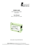
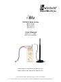
PROFIBUS Radio System
700-762-PFM11
700-761-PFM11
700-762-PFS11
700-761-PFS11
User Manual
Edition 1/11.11.2009
HW1 & FW1 and higher
Order number of viBlu100 manual: 900-761-PFx11
Order number of viBlu 200 manual: 900-762-PFx11
Systeme Helmholz GmbH • Hannberger Weg 2 • 91091 Großenseebach
Fon: +49 9135 7380-0 • Fax: +49 9135 7380-110 • E-Mail: [email protected] • Internet: www.helmholz.de
All rights are reserved, including those of translation, reprinting,
and reproduction of this manual, or parts thereof. No part of this
manual may be reproduced, processed, copied, or transmitted in
any way whatsoever (photocopy, microfilm, or other method)
without the express written permission of Systeme Helmholz
GmbH, not even for use as training material, or using electronic
systems. All rights reserved in the case of a patent grant or
registration of a utility model or design.
Copyright © 2009 by
Systeme Helmholz GmbH
Hannberger Weg 2, 91091 Grossenseebach, Germany
Note:
We have checked the content of this manual for conformity with
the hardware and software described. Nevertheless, because
deviations cannot be ruled out, we cannot accept any liability for
complete conformity. The information in this manual is regularly
updated. When using purchased products, please heed the latest
version of the manual, which can be viewed in the Internet at
www.helmholz.de, from where it can also be downloaded.
Our customers are important to us. We are always glad to receive
suggestions for improvement and ideas.
Step and SIMATIC are registered trademarks of SIEMENS
Revision history of this document:
Edition
1
Date
Revision
1st version
Contents
5
1
Safety Information
7
1.1
General
7
1.2
Restriction of access
8
1.3
Information for the user
8
1.4
Use as intended
8
1.5
Avoiding use not as intended!
8
2
Installation and Mounting
9
2.1
Mounting orientation
9
2.2
Minimum clearance
9
2.3
Mounting using a DIN rail adapter
10
3
System Overview
11
3.1
Radio transmission
11
3.2
Application and function description
12
3.3
Connections
13
3.4
LED displays
13
3.5
Items supplied
13
3.6
Accessories
13
3.6.1
3.6.2
3.6.3
Manual
Antenna technology
Other accessories
13
14
14
4
Configuration of the radio modules
15
4.1
Overview
15
4.2
Installation of the USB interface driver
15
4.3
Configuration of the modules
20
4.3.1
4.3.2
4.3.3
4.3.4
Excluding WLAN
Diagnostic slave
Information about address assignment
Saving and loading configurations
21
22
22
23
4.4
Enhancing operating and system reliability
23
4.4.1
Avoiding a system stop
24
viBlu
4.4.2
Implementing error detection
24
5
Diagnostic slave
25
5.1
Overview
25
5.2
Inclusion in the GSD file
25
5.3
Configuration of the viBlu diagnostic slaves
25
5.4
How it works
26
5.5
Use in the PLC
26
5.6
Description of the diagnostic blocks
27
5.6.1
5.6.2
5.6.3
5.6.4
5.6.5
5.6.6
5.6.7
5.6.8
Block 0: General diagnostic data
Block 1: Slave addresses
Block 2: State of PROFIBUS connections to slaves
Block 3: Response times of the slaves
Block 4: Number of RF repeat telegrams
Block 5: Number of retries because of RF disturbance
Block 6: Number of retries on DP side
Block 7: Average data transmission rate
27
28
28
28
28
29
29
29
6
Information / troubleshooting
30
6.1
Positioning and aligning the antenna
30
6.2
Improving noise immunity
30
6.3
Frequently asked questions
31
7
Appendix
32
7.1
Technical data viBlu 100
32
7.2
Technical data viBlu 200
33
7.3
Pin assignment
34
7.4
Further documentation
34
Notes 35
6
viBlu
1
Safety Information
Please observe the safety information given for your own and
other people's safety. The safety information indicates possible
hazards and provides information about how you can avoid
hazardous situations.
The following symbols are used in this manual.
!
i
Caution, indicates hazards and sources of error
Gives information
Hazard, general or specific
Danger of electric shock
1.1
General
The viBlu radio module is only used as part of a complete system.
!
The operator of a machine system is responsible for observing
all safety and accident prevention regulations applicable to the
application in question.
During configuration, safety and accident prevention rules
specific to the application must be observed.
Emergency OFF facilities according to EN 60204 / IEC 204
must remain active in all modes of the machine system. The system
must not enter an undefined restart.
Faults occurring in the machine system that can cause
damage to property or injury to persons must be prevented by additional
external equipment. Such equipment must also ensure entry into a safe
state in the event of a fault. Such equipment includes electromechanical
safety buttons, mechanical interlocks, etc. (see EN 954-1, risk
assessment).
Never execute or initiate safety-related functions using the
operator terminal.
viBlu
7
1.2
Only authorized persons
must have access to the
radio modules!
Restriction of access
The radio modules are open equipment and must only be
installed in electrical equipment rooms, cabinets, or housings.
Access to the electrical equipment rooms, barriers, or housings
must only be possible using a tool or key and only permitted to
personnel having received instruction or authorization. See also
Section 2.
1.3
Information for the user
This manual is addressed to anyone wishing to configure or
install the viBlu radio module.
It is intended for use as a programming manual and reference
work by the configuring engineer. It provides the installing
technician with all the necessary data.
The viBlu radio system is for use in PROFIBUS networks.
Depending on the application, the configuring engineer, user,
and installing technician must observe the standards, safety and
accident prevention rules applicable in the particular application.
The operator of the automation system is responsible for
observing these rules.
1.4
Use as intended
The viBlu radio module must only be used as a communication
system as described in the manual.
1.5
Avoiding use not as intended!
Safety-related functions must not be controlled via the viBlu radio
system alone.
8
viBlu
2
Installation and Mounting
Installation of the viBlu radio system must be effected in
compliance with VDE 0100 / IEC 364. Because it is an “OPEN
type” device, you must install it in a (switching) cabinet.
However, please not that the antenna of the device must not be
mounted inside the cabinet but outside. Ambient temperature: 0
ºC – 60 ºC.
Before you start installation work, all system components
must be disconnected from their power source.
Danger of electric shock!
During installation, application-specific safety and accident
prevention rules must be observed.
2.1
Mounting orientation
The viBlu radio module can be installed in any orientation.
However, please ensure that the antennas of the two
communication stations have the same alignment.
2.2
Minimum clearance
Minimum clearances must be observed because
•
as from > 10 cm between the viBlu radio module and
operating personnel, the health hazard due to exposure to
radio waves is minimized
•
it provides space to insert and remove modules
•
it provides space to route cables
•
the mounting height of the radio module is increased to
35 mm
The following diagram shows the minimum clearances between
adjacent module subracks and to neighboring cabinet walls,
equipment, cable ducts etc. for the viBlu radio module.
viBlu
9
2.3
Mounting using a DIN rail adapter
By using a DIN rail support (Order No.: 700-751-HSH10) it is
possible to mount the viBlu radio module on a DIN rail in a
switching cabinet.
10
viBlu
3
System Overview
3.1
Radio transmission
With the viBlu radio system, a proprietary Bluetooth protocol is
used for radio transmission in the license-exempt 2.4 GHz ISM
frequency band. A basic distinction is made between three classes
of Bluetooth systems, class 1, class 2, and class 3. The
communication process is identical in all three classes. They only
differ by their transmission powers. The following table provides
an overview of the class of a Bluetooth device and the possible
range in unobstructed radio transmission.
Class
Max. transmission
power
Range
Class 1
100 mW
Approx.
100 m
Class 2
2.5 mW
Approx.
50 m
Class 3
1 mW
Approx.
10 m
The range data very much depend on external factors. For
example, metal affects the range very strongly because it reflects
electromagnetic waves. If there is not visual contact between the
two radio stations, for example, because of interposed walls, the
range is considerably reduced. A further factor is the radiation
pattern of the antennas used: the stronger the "gain" of an
antenna, the greater the directivity and the greater the possible
transmission distance.
The viBlu system cannot be strictly assigned to any of these
classes because the power can be set by the user up to 100 mW.
Please also note that Bluetooth devices rarely transmit constantly
with their maximum transmission power because it is controlled
automatically. If less power is required, the transmission power is
automatically reduced. A reduction in transmission power can
make sense, especially in halls with many reflections, because the
reflections are received with a small amplitude.
The advantage of Bluetooth radio solutions as compared with
WLAN, for example, is the FHSS (frequency hopping spread
spectrum) method used. With this method, transmission is not
on a single channel but jumps between many channels according
to a defined schedule. This reduces the probability that transient
narrow-band interference can disturb the radio channel currently
being used and allows use of alternative channels if interference
last for a longer time.
The FHSS method spreads the useful signal spectrum and
distributes the power in the frequency range. In this way, the
useful signal can be hidden in the noise and recovered with the
viBlu
11
hop sequence that is only known to the receiver. Bluetooth is
therefore considered to be intrinsically very tap-proof.
Like other solutions based on Bluetooth, the viBlu radio system
has the advantage of considerably better noise immunity from
WLAN systems already installed, which operate in a constant
frequency band. The modules can be notified of existing
interfering WLAN channels and exclude them from the frequency
hopping.
3.2
Application and function description
The viBlu radio system from Systeme Helmholz GmbH permits
wireless transmission of PROFIBUS data. It is ideal for PROFIBUS
connections for which cable-bound transmission is not possible,
for example, rotating machine elements. Nevertheless, from the
point of view of the PLC, the PROFIBUS data are transmitted
completely transparently like on a cable. No configuration is
required therefore in the PLC.
For successful PROFIBUS transmission by radio, at least one radio
master and one radio slave are required. The radio master is
connected to a PROFIBUS master and the radio slave, to a
PROFIBUS slave. At the master end, further cable-bound
PROFIBUS slaves can be connected without impairing the radio
link. The following diagram shows a possible configuration of a
radio network with viBlu 200 radio modules.
The data transmission can be established as a point-to-point
connection between a radio master and a radio slave or as a pointto-multipoint connection between a radio master and multiple
radio slaves. With the viBlu 200 system, up to 3 DP slaves are
operated in a radio network with one viBlu master. It is
immaterial whether all three DP slaves are connected to a single
viBlu slave or whether each DP slave depends on its own viBlu
slave. The maximum PROFIBUS transmission rate is 1.5 MBps.
The viBlu 100 system can only be operated with one DP slave in a
radio network. The maximum PROFIBUS transmission rate is
187.5 kBps.
12
viBlu
The constant PROFIBUS transmission rate in both systems is
93.75 kBps at the slave end.
The viBlu master also offers the possibility of integrating a
diagnostics slave into the PLC for diagnosing the radio link.
3.3
Connections
Each viBlu radio module has a 9-way SubD connector for the
PROFIBUS, a 24-volt power supply, a RPSMA female connector for
connecting a 2.4 GHz antenna and a USB connection for
parameterization.
3.4
LED displays
The LEDs on the top of the device inform you about its operating
status.
LED “Bus Error” (red):
This LED displays a PROFIBUS error at the master end. This LED is
always off at the slave end.
LED “Connect” (blue):
If this LED is on or flashing, this indicates that a radio link has
been established and Bluetooth telegrams can be exchanged.
LED “Radio Login” (yellow):
If this LED is on, the radio slave was unable to connect to the
master end. This can occur, in particular, if address assignment is
wrong.
LED “Transmission” (green):
If this LED is on, PROFIBUS data are being transmitted by radio.
LED “On” (green):
Indicates that the device is correctly supplied with power and that
the operating system is running.
3.5
viBlu
Items supplied
•
viBlu 100/200 master or slave
•
Connector for the power supply
•
CD with “RadioParam” parameterization software
3.6
Accessories
3.6.1
Manual
•
viBlu 100-Manual, German/English
900-761-PFX11
•
viBlu 200-Manual, German/English
900-762-PFX11
13
3.6.2
•
Magnetic foot antenna 5dBi
700-889-ANT01
•
Omnidirectional antenna 8dBi
700-889-ANT02
•
Directional antenna 8dBi
700-889-ANT03
•
Directional antenna 18dBi
700-889-ANT04
3.6.3
14
Antenna technology
Other accessories
•
Power supply adapter with plug
•
DIN rail adapter
on request
700-751-HSH01
viBlu
4
4.1
Configuration of the radio modules
Overview
Configuration of a viBlu radio network is performed on PCs using
the “RadioParam V1” software. This software supplied with
module and can alternatively be downloaded from
www.helmholz.de.
The software is executable on any Windows 2000/XP computer.
The configuration of a radio module can be stored in a project file
on the PC.
You can use a normal commercial type USB cable to link the PC
to the viBlu radio module.
4.2
Installation of the USB interface driver
If this is the first time a viBlu radio module is being connected to
the PC, the operating system will try to install a suitable driver.
This driver provides the interface between the USB interface and
the operating system (Windows).
This initialization can take some time and goes through the
following steps:
viBlu
15
16
•
The operating system starts an installation wizard that
performs the installation, which is largely automatic. In the
first step, you must enter whether the driver is to be searched
for online or locally.
•
To be able to specify the search path for the driver (generally
the CD supplied), it is necessary to make the following setting
and confirm it with “Next.”
viBlu
viBlu
•
The next step is a prompt to specify the location of the driver.
It is generally enough to set a checkmark next to “Search
removable media…” and then to click the “Next” button.
•
If the viBlu CD is in a local drive, the search for the driver
now begins.
•
If a Windows XP compatibility query appears, confirm with
the button “Continue installation.” The driver is then installed.
17
18
•
After successful installation, the operation is completed by
clicking the “Finish” button.
•
The operating system starts the installation wizard a second
time to install the virtual COM port driver, too. The
installation steps are identical to the procedure described
above.
viBlu
•
viBlu
A new COM port has now been added in the device manager.
This COM port must be selected in the RadioParam software
to be able to communicate with the viBlu radio module.
19
4.3
Configuration of the modules
To be able to transmit PROFIBUS by radio, the radio master and
radio slave must be informed of each other's existence. Initial
configuration of a pair of communicating radio stations is best
performed as follows.
The first connect a 24V power supply to the viBlu master.
Connect the viBlu master to the PC via USB and then start
RadioParam. In the software, select the appropriate COM port.
The user interface of the software is divided into two parts for
separate configuration of the master and slave. On the left-hand
side, you can parameterize the radio master and on the righthand side, the radio slave.
Click the “Load from module” button on the master side. The
current configuration of the viBlu master is loaded and entered
into the fields on the left-hand side. The master side of the user
interface then looks like this.
Now enter the MAC address of the master in the “Master MAC
address” field on the slave side. Then assign a radio address in the
range 1 to 99 in the station address field. Check your address data
before continuing. The software supports you by showing
implausible data in red. For initial commissioning with only one
viBlu master and one viBlu slave, you should also check that the
checkmark is activated next to “PTP with this slave.”
To minimize data traffic via this radio interface, the PROFIBUS
data are analyzed and filtered. For this purpose, it is necessary to
define in a table which DP master is allowed to communicate
with which DP slave via the radio interface. Click the “PB
addresses” button. A window then opens with a table with 3 rows.
20
viBlu
Depending on how many DP slaves, up to 3, you want to
connect, activate the corresponding number of slaves in the
“Active” column. Please note, don’t activate more than one DP
slave in the viBlue100 system. Then enter the DP address of your
PROFIBUS master at any position in the “Master” column. In the
“Slave” column, you must enter the DP addresses of your
PROFIBUS slaves that are connected to the viBlu slave. It is
immaterial whether you have connected multiple DP slaves to
one viBlu slave or whether you have connected one DP slave each
to multiple viBlu slaves.
To save the set configuration of the radio master, click the “Save
in module” button on the master side. This updates the
configuration of the device.
Connect to the viBlu slave to a 24V power supply. Now connect
the slave to the PC through a USB cable and select the appropriate
COM port in RadioParam. Check again that no fields are
displayed red and then click the “Save in module” button on the
slave side.
You can now connect the viBlu master to the DP master via
PROFIBUS and connect the viBlu slave to the DP slave. After that,
you can start the PLC. If your settings are correct, after several
seconds, all LEDs should light up or flash on the viBlu master and
viBlu slave except for the “bus error” LED.
!
For many I/O data, it
may be necessary to
increase the filter time.
The typical values are:
100ms to 2s
!
The more WLAN
channels you exclude,
the lower the data
throughput because less
bandwidth is available
for Bluetooth
viBlu
The viBlu system provides you with several possibilities of
influencing the quality of the data transmission. For example,
you can set the transmission power of the module in dBm in the
“RF power” list. At the highest setting 17 dBm, the device
transmits at maximum power. Considering that an antenna with
3dBi is used, the maximum power is approximately 100mW.
Moreover, transient radio interference can be suppressed by
specifying the PROFIBUS filter time. If a slave is not accessible due
to transient radio disturbances, a bus error will not be signaled
until after this time has elapsed. The settable range is 0*0.1s to
255*0.1s (25.5s). For commissioning, a filter time between 1s and
2s is advisable. After that, the filter time can be reduced again.
If you want to use a diagnostic slave or want to exclude certain
WLAN channels, also make the settings described in the next two
sections.
4.3.1
Excluding WLAN
Bluetooth and WLAN both work in the 2.4GHz ISM band. A
WLAN channel would interfere with about 20 of the 80 possible
Bluetooth channels. You can notify the radio system of up to
three existing WLAN channels by selecting the checkmark
21
“Exclusion of WLAN channels” for up to three channels and, in
the field that then appears, entering one WLAN channel each in
the range 1 to 13. The viBlu system no longer uses these channels
and a WLAN will no longer interfere with the radio
communication of the system.
4.3.2
Diagnostic slave
To be able to use the diagnostic slave functionality, you must
select “Activate PB diagnostics” in RadioParam. Two fields appear.
In the “Diagnosis address DP Master” field, enter the DP address if
In addition to the setting
the PROFIBUS masters, for example, a CPU, and in the second
in RadioParam, the
field “Diagnosis address DP Slave,” assign a DP address to the
diagnostic slave must
also be configured in the diagnostic slave. In the DP master, you can read the diagnostic
data via SFCs and then evaluate them.
PLC.
!
Please note that you must configure the diagnostic slave in the
PLC, too. For more information about the diagnostic slave, see
Section 5.
4.3.3
Information about address assignment
For successful configuration of viBlu radio network, a number of
different addresses have to be assigned, which are explained in
more detail below.
MAC address:
The MAC address is an address defined once by the viBlu master.
You must notify a viBlu slave of this address, so that it can log
onto the viBlu master via radio. Always make sure that the MAC
addresses are identical to the master MAC address on all slaves.
22
viBlu
Address assignment in point-to-point connections:
Each radio station requires its own radio address for
identification, its station address. To be able to communicate with
other stations, each station requires the station address of its
communication partner; this is its partner address. If the radio
link consists only of one viBlu master and one viBlu slave, select
the checkmark in front of “PTP with this slave” and enter
different station addresses on the master and slave sides. The
partner address is automatically entered by RadioParam and can
therefore not be edited.
Address assignment in point-to-multipoint connections:
In the case of a radio network with multiple viBlu slaves, you
must first clear the checkmark from in front of “PTP with this
slave.” The partner address of the master is then automatically
changed to broadcast address 0 and the slave side is extended to a
total of three slaves. To be able to use multiple slaves, you must
first activate the correct number of slaves by clicking on the tab
for each slave and then selecting the checkmark in front of
“Activate this slave.” In all three slaves, you must then assign a
dedicated station address and enter the MAC address of the
master. Once you have completed configuration of the slaves, you
must connect one of the slaves with the PC, select the tab of that
slave, and transfer its parameterization to the module by clicking
“Save in module.” Proceed in this way for all the remaining slaves
that you want to use.
4.3.4
Saving and loading configurations
Once you have completed an entire configuration, you can save it
by clicking “Save” or “Save as.” This is especially helpful if you
want to replace a radio station in a radio network, for example.
You can then load the configuration that is valid for this network
by clicking “Open,” which updates the station in question. Please
note that if you replace a viBlu master, the new configuration
must be transferred both into the master module and into each of
the viBlu slave modules by clicking the “Save in module” button.
Otherwise the new MAC address of the master will not be known
to these devices and communication will not be possible. If you
replace a slave, it is only necessary to transfer the configuration of
this slave into the slave. Other existing modules are not affected
because they already know the MAC address of the master.
4.4
Enhancing operating and system reliability
Because interferences of a natural or artificial nature can disturb
the radio path, it is advisable to take certain security measures to
detect failure or disturbance of radio communication and to avoid
this resulting in failure of the automation system.
viBlu
23
4.4.1
Avoiding a system stop
By integrating error OBs, for example, it is possible to indicate
and respond to errors in the PROFIBUS communication in a
Siemens PLC.
Just inserting the empty OB 86 (module failure) prevents the
automation system from entering the STOP state as a result of
transient disturbances in PROFIBUS communication.
However, it is possible to store a program in OB 86 that, for
example, outputs a warning if the failed I/Os do not resume
operation immediately.
For statistical purposes, it is possible to integrate an error counter,
too, as described in the next section.
4.4.2
Implementing error detection
The simplest type of error diagnostics is demonstrated by the
example of the module failure OB (OB 86).
If transient disturbances occur in the PROFIBUS communication,
OB 86 is called (disturbance occurred). Once the disturbance has
been eliminated (radio link is not longer disturbed), the error OB
is run once more (disturbance gone).
// Error event detected => increment error counter
L #OB86_EV_CLASS
L B#16#39
==I
JC M001
// Error remedied => BE (or alternative code in M002)
L #OB86_EV_CLASS
L B#16#38
==I
JC M002
M001: L QB
INC 1
T QB
BEU
0
0
M002: BE
// If it is also to be recorded which station has failed // and what
type of error has caused this, the variables // 'OB86_MDL_ADDR'
and 'OB86_Z23' must be evaluated.
24
viBlu
5
5.1
Diagnostic slave
Overview
Every viBlu master includes a virtual diagnostics slave. With this
integrated diagnostic slave, you can diagnose the radio interface
to respond in your PLC to changing ambient conditions that
influence the quality of radio transmission.
5.2
Inclusion in the GSD file
Before you can use the data of the diagnostic slave, you must
include the diagnostic slave in the PROFIBUS network. The first
step toward this is to include the GSD file supplied with the
module once in Step 7. This is done as follows:
-
Copy the files viBlu.GSD and viBlu.bmp into the directory
…\Step7\S7TMP
-
Open the hardware configuration in the Simatic Manager
-
Click “Options” on the menu bar
-
Click the “Install GSD files”
5.3
Configuration of the viBlu diagnostic slaves
To be able to use the diagnostic slave functionality, you must
configure the viBlu diagnostic slave in the PLC as follows.
-
In the hardware catalog, you can now include the diagnostic
slave in your PROFIBUS network under “PROFIBUS-DP/
Additional field devices/General/viBlu”
-
Move the “viBlu_Diagnose: 32 Byte In/Out” module to the
first slot of the viBlu slave
-
Assign a DP address for the diagnostic slave and then load the
hardware configuration into your DP master
If you do not want to use the diagnostic slave, make sure you do
not configure it in your PROFIBUS network. Otherwise, bus errors
may occur because the DP master cannot find a DP slave.
viBlu
25
5.4
How it works
The following diagram shows the principle of working with the
diagnostic slave.
Step 1:
The PLC selects one of the 8 possible diagnostic blocks.
Step 2:
The diagnostic slave provides 32 bytes of diagnostic data in the
output memory.
Step 3:
The PLC imports the diagnostic block.
5.5
Use in the PLC
To be able to communicate with the diagnostic slave from the DP
master, as shown above, you must use the both system functions
SFC 14 (DPRD_DAT) for reading and SFC 15 (DPWR_DAT) for
saving.
The diagnostic slave has a total of 8 blocks of 32 bytes of
diagnostic data each. You must first notify the diagnostic slave
once of the block that you wish to read out using the SFC 15. In
the example below, the data set is transmitted to the diagnostic
slave from data block DB1 as from data byte 0. The storage
address of the diagnostic slave is 100 hex. The error code is stored
in flag word 20.
CALL "DPWR_DAT"
LADDR := W#16#100
RET_VAL:= MW20
RECORD := P#DB1.DBX0.0 BYTE 32
Byte 0 of the data set states which diagnostic block you want to
read out subsequently, that is, 0 to 7.
26
viBlu
The diagnostic data partly consist of certain count values. To reset
these within the block, you must set the LSB in byte 1 to '1.' This
can be done, for example, with the following commands:
L B#16#01 // Loads value 1 into the register
T DB1.DBB1 // Transfers the register value to byte 1, DB1
SFC 15 must then be called again as shown above. Even though
only bytes 0 and 1 are decisive, you must transfer 32 bytes for
reasons of consistency. You should set the unused 30 bytes to
b#16#01.
To read out the selected side of the diagnostic slave, also memory
address 100 hex, you must use SFC 14. In the following example,
the received data are written in 32 flag bytes starting from flat
byte 200. The error code is stored in flag word 22.
CALL "DPRD_DAT"
LADDR := W#16#100
RET_VAL:= MW22
RECORD := P#M 20.0 BYTE 32
5.6
Description of the diagnostic blocks
5.6.1
Block 0: General diagnostic data
Byte
Value
0
Baud rate
1: 1.5 MBd
2: 500 kBd
3: 187.5 kBd
4: 93.75 kBd
5: 19.2 kBd
6: 9.6 kBd
1
PROFIBUS filter time
1-255 (100ms – 25.5s)
2
Power-up counter
Number of times the viBlu master
has been powered up
3
Number of PROFIBUS errors
4/5
Number of RF repeats
How many telegrams the slave was
unable to answer
6/7
Number of slave failures
How many connection breaks.
8/9
Summator of all slave response
telegrams
10-23
Reserved
24
Transmission power
0 = 0dBm, …,17=17dBm
25
Station address
1-99
26
Partner address
0-99
27
Mode
0=Master
28-30
31
viBlu
Meaning
Reserved
Checkback response of selected
diagnostic block
0
27
5.6.2
Block 1: Slave addresses
Byte
Meaning
Value
0
DP address slave 1
1- 99
1
DP address slave 2
1- 99
2
DP address slave 3
1- 99
.
.
.
Reserved
31
Checkback response of selected
diagnostic block
1
Only available with viBlu 200 modules.
5.6.3
Byte
Block 2: State of PROFIBUS connections to slaves
Meaning
Value
0
State of slave 1
0- 10 (5: data exchange)
1
State of slave 2
0- 10
2
State of slave 3
0- 10
.
.
.
Reserved
31
Checkback response of selected
diagnostic block
2
5.6.4
Block 3: Response times of the slaves
Byte
Meaning
Value
0
Response time slave 1
x*10ms
1
Response time slave 2
x*10ms
2
Response time slave 3
x*10ms
.
.
.
Reserved
31
Checkback response of selected
diagnostic block
3
Only available with viBlu 200 modules.
5.6.5
Block 4: Number of RF repeat telegrams
Byte
Meaning
Value
0
RF retries slave 1
0-255
1
RF retries slave 2
0-255
2
RF retries slave 3
0-255
.
.
.
Reserved
31
Checkback response of selected
diagnostic block
4
Only available with viBlu 200 modules.
28
viBlu
5.6.6
Block 5: Number of retries because of RF disturbance
Byte
Meaning
Value
0
Number of retries slave 1
0-255
1
Number of retries slave 2
0-255
2
Number of retries slave 3
0-255
.
.
.
Reserved
31
Checkback response of selected
diagnostic block
5
Only available with viBlu 200 modules.
5.6.7
Byte
Block 6: Number of retries on DP side
Meaning
Value
0
Number of retries slave 1 (DP
side)
0-255
1
Number of retries slave 2 (DP
side)
0-255
2
Number of retries slave 3 (DP
side)
0-255
.
.
.
Reserved
31
Checkback response of selected
diagnostic block
6
Only available with viBlu 200 modules.
5.6.8
Byte
Block 7: Average data transmission rate
Meaning
Value
0
Average data transmission rate
slave 1
0-255 telegrams/second
1
Average data transmission rate
slave 2
0-255 telegrams/second
2
Average data transmission rate
slave 3
0-255 telegrams/second
.
.
.
Reserved
31
Checkback response of selected
diagnostic block
7
Only available with viBlu 200 modules.
If the diagnostic blocks are read and switched over cyclically, you
must check byte 31 in the PLC to see whether it contains the
number of the diagnostic block you require. Depending on the
data transmission rate and load, several CPU cycles may pass
before the right diagnostic block is received and displayed in the
PLC.
viBlu
29
6
6.1
Information / troubleshooting
Positioning and aligning the antenna
To ensure optimum signal transmission even over large distances,
you should observe a few basic rules when setting up your
antennas.
1. Mounts the antennas in a high location, all at the same height
is possible
2. Mount the antennas in such a way that they are aligned
parallel
3. Make sure that the antennas are within clear sight of each
other if possible
4. Always mount the antennas outside the cabinet
5. Keep the antennas away from heavy current circuits carrying
several amps, for example, converters and motors
6.2
Improving noise immunity
Disturbance voltages and currents can enter the device by
injection via each cable connected to a device and even via
connectors. The most important types of interference injection at
electrostatic discharges (ESD), for example, due to touching,
capacitive coupling, for example, crosstalk between parallel
conductors, inductive coupling, for example, due to loops and
galvanic disturbances, for example, due to common ground in
different circuits. In an environment subject to EMC disturbance,
interference injection can never be presented entirely, but it can
be minimized if certain measures are taken. The following
subsections are intended to explain a few basic rules by which
you can greatly improve the noise immunity of the viBlu system.
Grounding
To conduct away injected interference voltages via the shielding
of the cable or a connector, you should connect the FE
connection of a viBlu device through a low-resistance contact
using the shortest and thickest possible copper conductor with
the cabinet ground of your equipment.
Shielding
Always use shielded cable with the highest possible shield density
for interfaces with high data transmission rates, for example,
PROFIBUS. In the case of PROFIBUS, always connect to the shield
at both ends of the PROFIBUS cable.
Cable laying
Lay the data cables and power cables separately with a distance of
at least 20 cm between them and, if possible, in different cable
ducts.
30
viBlu
Preventing unwanted antennas
Interference voltages can also be injected via unused cable
conductors. Therefore route unused cable conductors to cabinet
ground at both ends.
Using metal bus connectors
Use metal connector shells for bus cables and connect these to the
cable shield.
PE conductor
Connect the PE conductors of the individual devices in your
system to the equipotential bonding terminal in a star topology.
Neutralizing interference sources
Make sure that electronic components that have been identified
as potential sources of interference are mounted in a metal
housing. In that case, interference cannot exit the housing and
disturb other devices.
Avoiding equalizing currents
Avoid equalization currents flowing via the FE connection
through the viBlu device. For this purpose, measure the current at
the FE connection of the viBlu device using a current probe. If a
high current is permanently flowing there, electrical isolation
should be implemented using a 100nF/230V X capacitor.
6.3
Frequently asked questions
The bus error LED on the viBlu master flashes although
everything seems to be working fine on the PROFIBUS?
-
A DP slave address has been set in the PROFIBUS table in
RadioParam that does not exist in the PROFIBUS network.
-
This can occur if the integrated diagnostic slave has been configured
with the “RadioParam” in the viBlu master, but not in the PLC.
If the viBlu master and viBlu slave are close together PROFIBUS
works but as soon as the distance is increased, the bus error LED
starts flashing?
-
Make sure the antenna is firmly connected to the RP-SMA connector
on the device.
-
Increase the RF power in the radio master and slave in
“RadioParam.”
-
Replace the antenna.
-
Or use an antenna with a higher “gain.”
If these tips do not help, contact our support, either by phone or
at [email protected].
If information about the viBlu device is also at hand (manual),
please also send this information.
viBlu
31
7
Appendix
7.1
Technical data viBlu 100
Order numbers
Master
Slave
700-761-PFM11
700-761-PFS11
Dimensions
130 x 68 x 30 mm (LxWxH)
Weight
Approx. 170g
Configuration interface
Type:
USB 1.1
Transmission rate:
Fullspeed 12MBps
Connector:
USB-B
Radio interface
Antenna connection RP-SMA, female connector
Baud rate
max. 700kBps
PROFIBUS
Connection:
SUB-D female connector, 9-way
Baud rates:
9.6 kBps … 187.5 kBps
Number of DP-Slaves: 1
Protocols:
DPv0 and DPv1
Power supply
Voltage:
Current consumpt.:
Connection:
+24V DC external (18-30 V DC)
100mA (typ. max.)
Screw connector supplied
Degree of protection IP20
Temperature
Operation
Transp. and storage
Special features
Quality assurance:
Maintenance:
32
0 °C…60°C
-25°C … 60°C
According to ISO 9001:2008
Maintenance-free (no battery, rechargeable
or non-rechargeable)
viBlu
7.2
Technical data viBlu 200
Order numbers
Master
Slave
700-762-PFM11
700-762-PFS11
Dimensions
130 x 68 x 30 mm (LxWxH)
Weight
Approx. 170g
Configuration interface
Type:
USB 1.1
Transmission rate:
Fullspeed 12MBps
Connector:
USB-B
Radio interface
Antenna connection RP-SMA, female connector
Baud rate
max. 700kBps
PROFIBUS
Connection:
SUB-D female connector, 9-way
Baud rates:
9.6 kBps…1.5 MBps
Number of DP-Slaves: 3
Protocols:
DPv0 and DPv1
Power supply
Voltage:
Current consumpt.:
Connection:
+24V DC external (18-30 V DC)
100mA (typ. max.)
Screw connector supplied
Degree of protection IP20
Temperature
Operation
Transp. and storage
Special features
Quality assurance:
Maintenance:
viBlu
0 °C…60°C
-25°C … 60°C
According to ISO 9001:2008
Maintenance-free (no battery, rechargeable
or non-rechargeable)
33
7.3
Pin assignment
Pin
1
2
3
4
5
6
7
8
9
Housing
7.4
SUBD connector PROFIBUS
B line, D+
Gnd
5V
A line, DFE
Further documentation
Internet: http://www.profibus.org/
34
viBlu
Notes
viBlu
35