1
User's Manual
0
User's Manual
, a brand integrated into Samsung’s network products, stands for a convenient
world (Polis) made safe (Police) through Samsung’s superior network performance (Internet
Protocol). Our 1- and 4-channel video servers and network cameras support a wide selection of
advanced network security system features including an Ethernet interface for convenient
Internet connection, various image compression standards such as MPEG-4 and JPEG, high
quality image transfer, basic web viewer, two-way audio, and network management software
enabling remote control and multi-channel management.
Preface
The user who installs and operates the product shall be aware of this manual and other
manuals referenced by this manual before the installation and operation and use it properly.
This manual and the software and hardware explained here are protected by copyright law.
All copy, reprint and translation to other languages of a part of or all contents of this user
manual without permission of Samsung Techwin Co., Ltd. are not allowed except for fair use
within the scope of copyright law.
1
User's Manual
Contents
Chapter 1. Overview......................................................................... 7
1.1.
SNM-128P ...................................................................................................................... 7
1.2.
System Requirements..................................................................................................... 7
1.3.
Supported Devices.......................................................................................................... 8
1.4.
Monitor Setup.................................................................................................................. 9
1.5.
Software Installation...................................................................................................... 10
1.6.
Deleting Program DB .................................................................................................... 14
1.6.1.
For Windows XP .................................................................................................... 14
1.6.2.
For Windows Vista................................................................................................. 14
1.7.
Program Login .............................................................................................................. 14
Chapter 2. SNM-128P Monitor ....................................................... 15
2.1
Interface ........................................................................................................................ 15
2.1.1
View Areas............................................................................................................. 15
2.2
Toolbars ........................................................................................................................ 17
2.3
Site Mode...................................................................................................................... 18
2.3.1
Creating & Deleting Folders .................................................................................. 18
2.3.2
Registering & Deleting Units.................................................................................. 18
2.3.3
Renewing Unit Information .................................................................................... 21
2.3.4
Viewing Video ........................................................................................................ 21
2.4
Screen Layout Mode..................................................................................................... 21
2.4.1
Registering & Deleting Screen Layouts................................................................. 21
2.4.2
Viewing Video ........................................................................................................ 22
2.5
Map Mode ..................................................................................................................... 22
2.5.1
Map Editor ............................................................................................................. 22
2.5.2
Viewing Map .......................................................................................................... 27
2.5.3
Controlling Mapped Devices.................................................................................. 27
2.5.4
Aligning Map Windows .......................................................................................... 28
2.5.5
Switching Map ....................................................................................................... 28
2.6
Monitor Screen.............................................................................................................. 28
2.6.1
Screen Interface .................................................................................................... 28
2
User's Manual
2.6.2
Split Screen............................................................................................................ 29
2.6.3
Full Screen............................................................................................................. 29
2.6.4
Switching Screens ................................................................................................. 29
2.6.5
Caption Information ............................................................................................... 29
2.6.6
Video Transfer Speed ............................................................................................ 29
2.6.7
Video Resolution.................................................................................................... 30
2.6.8
Streaming............................................................................................................... 30
2.6.9
Event...................................................................................................................... 30
2.6.10
Saving Images ....................................................................................................... 31
2.6.11
PTZ Control ........................................................................................................... 31
2.6.12
Audio Control ......................................................................................................... 32
2.6.13
Buffering................................................................................................................. 32
2.6.14
Closing All Monitors ............................................................................................... 32
2.6.15
Event Log............................................................................................................... 32
2.6.16
Status & Action....................................................................................................... 32
2.6.17
Viewing Videos ...................................................................................................... 33
2.6.18
Processing Events ................................................................................................. 33
2.6.19
Instant Viewer ........................................................................................................ 33
2.6.20
Instant Player......................................................................................................... 34
2.6.21
Alarm Control Station............................................................................................. 34
2.7
Status & Action.............................................................................................................. 36
2.7.1
Status & Action Information ................................................................................... 36
2.7.2
Viewing Videos ...................................................................................................... 36
2.7.3
Selecting Different Event Alert Types by Unit ........................................................ 36
2.8
Searching Event............................................................................................................ 37
2.9
User Settings ................................................................................................................ 38
2.10
Changing Passwords .................................................................................................... 38
2.11
Setting Up Options........................................................................................................ 38
2.11.1
Display ................................................................................................................... 39
2.11.2
Recording .............................................................................................................. 40
2.11.3
Event Alert ............................................................................................................. 41
2.11.4
Monitor Layout Manager........................................................................................ 42
2.11.5
Instant Auto Action ................................................................................................. 44
2.12
Searching Error Log...................................................................................................... 50
3
User's Manual
Chapter 3. SNM-128P Playback ..................................................... 51
3.1
Interface ........................................................................................................................ 51
3.1.1
View Areas............................................................................................................. 51
3.1.2
Toolbar ................................................................................................................... 52
3.2
Opening Unit & Backup File.......................................................................................... 53
3.3
Search........................................................................................................................... 53
3.3.1
Image Information Display..................................................................................... 53
3.3.2
Changing Search Timeline .................................................................................... 53
3.3.3
Selecting Channels................................................................................................ 54
3.3.4
Calendar Search.................................................................................................... 54
3.3.5
Log Information Display & Search ......................................................................... 54
3.3.6
Searching Text ....................................................................................................... 54
3.3.7
Smart Search......................................................................................................... 55
3.3.8
Searching Thumbnails ........................................................................................... 56
3.4
Playback ....................................................................................................................... 57
3.4.1
Playback Buttons ................................................................................................... 57
3.4.2
Playing Audio ......................................................................................................... 57
3.4.3
Text ........................................................................................................................ 57
3.5
Image Control ............................................................................................................... 58
3.5.1
Zoom/Brightness/Contrast Control ........................................................................ 58
3.5.2
Saving Images ....................................................................................................... 58
3.5.3
Printing Images...................................................................................................... 58
3.6
Backup Feature............................................................................................................. 59
3.7
Backup Log ................................................................................................................... 59
3.8
Setting Up Options........................................................................................................ 60
3.8.1
Captions................................................................................................................. 60
3.8.2
Spilt Screen Auto Control....................................................................................... 60
3.9
Simple Mode Playback ................................................................................................. 60
Chapter 4. SNM-128P Setup .......................................................... 61
4.1
Program Login .............................................................................................................. 61
4.2
Interface ........................................................................................................................ 61
4.2.1
Site Tree ................................................................................................................ 62
4.2.2
Menu...................................................................................................................... 62
4
User's Manual
4.2.3
4.3
Settings Page ........................................................................................................ 62
Setup Guidelines........................................................................................................... 63
4.3.1
System Setup ........................................................................................................ 63
4.3.2
Screen ................................................................................................................... 66
4.3.3
Date/Time .............................................................................................................. 67
4.3.4
Network.................................................................................................................. 68
4.3.5
COM Port............................................................................................................... 71
4.3.6
PTZ ........................................................................................................................ 72
4.3.7
Users ..................................................................................................................... 74
4.3.8
IP Filtering.............................................................................................................. 75
4.3.9
Disk ........................................................................................................................ 76
4.3.10
System Log............................................................................................................ 76
4.3.11
MD ......................................................................................................................... 77
4.3.12
Sensor Setup ......................................................................................................... 77
4.3.13
Text ........................................................................................................................ 78
4.3.14
Event Action........................................................................................................... 78
4.3.15
System Event......................................................................................................... 79
4.3.16
E-Mail..................................................................................................................... 80
4.3.17
Event Preset .......................................................................................................... 80
4.3.18
Digital Input & Output............................................................................................. 81
4.3.19
Event Schedule...................................................................................................... 81
4.3.20
Save....................................................................................................................... 82
4.3.21
Program ................................................................................................................. 83
4.3.22
Audio...................................................................................................................... 84
4.3.23
Miscellaneous ........................................................................................................ 84
4.3.24
SVR-1650/1640/950 Setup.................................................................................... 85
4.3.25
SVR-940/450 Setup............................................................................................... 92
4.3.26
Web Server & IP Camera Setup.......................................................................... 107
Chapter 5. Scheduled Backups .................................................... 110
5.1
Backup Setup...............................................................................................................111
5.1.1
Backup File ...........................................................................................................111
5.1.2
Password Setup....................................................................................................111
5.1.3
Backup File Retention Period Setup.................................................................... 112
5.1.4
Backup Drive Setup ............................................................................................. 112
5.1.5
Auto Removal Setup............................................................................................ 113
5.1.6
Backup Data Area Setup ..................................................................................... 113
5
User's Manual
5.1.7
Backup Schedule Setup ...................................................................................... 114
5.1.8
Backup System Tray Icon.................................................................................... 115
5.1.9
Creating Backup File ........................................................................................... 115
5.2
Backup Status ............................................................................................................. 116
5.2.1
Backup Operation Status Table ........................................................................... 116
5.2.2
Viewing Detailed Information ............................................................................... 117
5.2.3
Aborting Backups................................................................................................. 117
The contents of this manual may vary from the actual software depending on its upgrade status,
and its design and specifications may change without prior notice for the improvement of
product performance.
6
User's Manual
Chapter 1. Overview
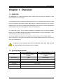
1.1. SNM-128P
The SNM-128P is a central surveillance system solution that can monitor a maximum of 1000
units installed in remote locations.
This software provides convenient monitoring features such as real-time video monitoring, video
search and backup, and various system setup options. It supports a maximum of 6 monitors,
enabling you to monitor up to 256 channels simultaneously in real time. It is also equipped with
efficient search features including specific area and text searches.
The SNM-128P reports on the real-time situation of registered units via various methods,
helping you understand and take appropriate countermeasures as quickly as possible. It also
offers a feature to save and search event logs.
To manage multiple units efficiently, the software provides Screen Layout and Map options.
With a maximum of 6 monitors, this software can manage multiple networks as well as save
error logs simultaneously.
To register and use products other than the SVR-3200, 1680, 1660, 1645, 960, and
45, their firmware version must be v2.8.0 or higher.
1.2. System Requirements
Minimum
Recommended
Intel Core2 duo E6750
Intel Core2 Quad Q6700
or higher
or higher
Main Memory
2GB
2GB or higher
Video Memory
256MB
512MB or higher
CPU
Display Resolution
1280 x 1024 (with 32bit color) or higher
Hard Disk
1GB or higher
Operating System
Windows XP Professional / Window Vista Business
Miscellaneous
DirectX 9.0 or higher
7
User's Manual
1. When using 6 monitors, do not activate the Live Viewer mode for more than 4
monitors simultaneously. Activating the mode for more than 4 monitors at the
same time may decrease the display quality or performance of the software.
2. The performance of the monitoring system may be decreased if too many
events are happening simultaneously in units registered to the SNM-128P. To
maintain optimal performance of your monitoring system, minimize the
chance of unnecessary events by changing the unit settings.
The SNM-128P is optimized for Windows XP with Service Pack 3 and the Windows Vista series.
To prevent viruses and malicious code on your monitoring system, install an anti-virus program
and get the latest Windows updates for the operating system on a regular basis.
For real-time multi-channel monitoring, 2GB of memory is recommended for 128 channels and
4GB for 256.
4GB of memory is also recommended when using 512 or more units.
Using the default video drivers provided by Microsoft in conjunction with DirectX may cause
flickering or decrease the display quality of the software. In such cases, uninstall DirectX or get
the latest drivers for the corresponding video card.
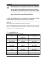
1.3. Supported Devices
The SNM-128P supports devices as listed below.
Category
DVR
Model Name
SVR-3200/1680/1660/
1645/960/945
Firmware
1.0.0 or higher
Network Camera
SNC-550
2.8.0 or higher
Network Camera
SNP-3300
2.8.0 or higher
Network Camera
SNP-3300A
2.8.0 or higher
Network Camera
SNP-1000
2.8.0 or higher
Network Camera
SNP-1000A
2.8.0 or higher
Video Server
SNS-100
2.8.0 or higher
Video Server
SNS-400
2.8.0 or higher
DVR
SVR-1630
4.8.0 or higher
DVR
SVR-1650
2.8.0 or higher
DVR
SVR-1640
2.8.0 or higher
DVR
SVR-950
2.8.0 or higher
DVR
SVR-940/450
1.4.0 or higher
8
User's Manual
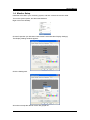
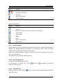
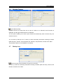
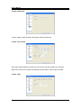
1.4. Monitor Setup
Install the VGA card in your monitoring system, and then connect the monitor cable.
Turn on the system power, and then start Windows.
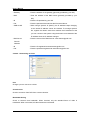
Right-click on the desktop.
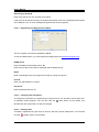
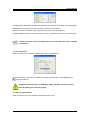
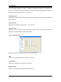
Choose Properties. (On Windows Vista choose Personalize then Display Settings.)
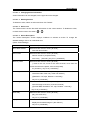
The Display Settings window appears.
Click the Settings tab.
All monitors except the default monitor are grayed out.
9
User's Manual
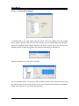
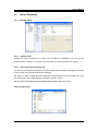
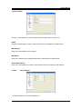
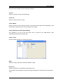
To activate another monitor, place the cursor on the monitor icon, and then right click on the
mouse.
Choose Attached, and then click "Apply" at the bottom of the Display Settings window.
Adjust the resolution of the newly activated monitor to the SNM-128P recommended resolution.
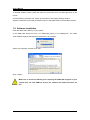
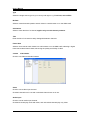
1.5. Software Installation
Insert the SNM-128P USB key to your system.
In the SNM-128P Setup CD menu, run "SNM-128P_Setup_v1.x.x-USBKey.exe". The SNM128P software requires administrator permissions to be installed.
Select your language, and then click "OK".
Click "I agree".
Make sure to insert the USB key prior installing the SNM-128P program. If your
system does not have USB key drivers, the software will install the drivers for
you.
10
User's Manual
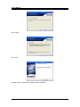
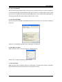
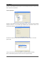
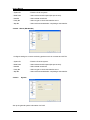
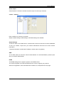
The picture above is the initial window of the USB key driver installation.
When the SNM-128P USB key driver installation window appears, click "Next".
Check "I accept the terms in the license agreement," then click "Next".
Check "Complete," and then click "Next".
11
User's Manual
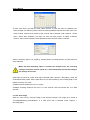
Click "Install".
Click "Yes".
Clicking "Finish" completes the USB key driver installation.
12
User's Manual
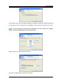
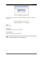
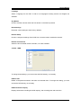
If the USB key drivers are successfully installed, the installation software automatically brings up
a new window to verify the license key of the USB key. Check the license, and then click "Next".
The trial versions of the drivers are available to try for 30 days. The software
becomes disabled after the 30 day trial period.
Select the items to install, and then click "Next".
Choose an installation folder, and then click "Install".
13
User's Manual
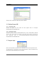
Clicking "Close" completes the SNM-128P program installation.
1.6. Deleting Program DB
1.6.1. For Windows XP
Uninstall the program, and then delete the entire program folder at "C:\Program
Files\SAMSUNG TECHWIN\SNM-128P".
1.6.2. For Windows Vista
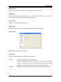
Uninstall the program, and then in Windows Explorer click > View > Folder Options. Under the
View tab, check "Show hidden files and folders" under Hidden files and folders. Then delete the
entire
"SNM-128P"
folder
at
"C:\Users\UserName\AppData\Local\VirtualStore\Program
Files\SAMSUNG TECHWIN\SNM-128P".
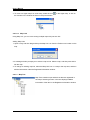
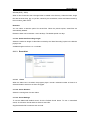
1.7. Program Login
Enter an ID and password, and then click "OK". SNM-128P runs if the ID and password match.
The default login ID is "Administrator" and the default password is "12345". Permissions to run
the program are limited depending on the user settings.
14
User's Manual
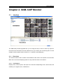
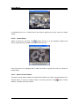
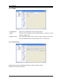
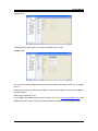
Chapter 2. SNM-128P Monitor
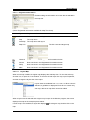
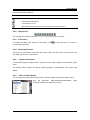
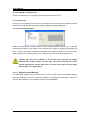
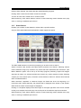
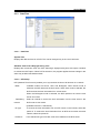
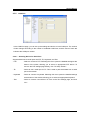
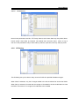
2.1
Interface
Toolbar
Unit Explorer
Main View
Thumbnails
Event Viewer
The SNM-128P provides upgraded UIs; you can drag and drop to move or dock any object on
the screen and customize the screen elements fit to your needs. (For customizing the UI across
multiple monitors, please refer to section 2.11.4, Monitor Layout Manager.)
2.1.1
View Areas
The Control Center screen consists of three different view areas: Unit Explorer at the left side,
Main View in the center displaying video or map, and Event View on the bottom.
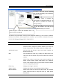
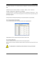
2.1.1.1 Unit Explorer
Displays units, screen layouts, and maps in the tree list corresponding to the current mode, and
enables you to register, edit, or delete them.
15
User's Manual
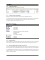
(Chart: Unit Explorer Icons)
Icons
Description
A folder that contains registered units.
A sub folder under a registered unit; you can add sub folders under a registered
unit for management.
Failed to connect a non-hard disk unit.
Failed to login to a non-hard disk unit.
Logged in to a non-hard disk unit.
Alarmed unit: when an alarm is activated, the target icon blinks red for 5 seconds.
Unit under watch; every video channel of the target unit is under watch.
Logged into a hard disk unit (DVR).
Failed to login to a hard disk unit (DVR).
Alarmed unit: when an alarm is activated, the target icon blinks red for 5 seconds.
Failed to connect to a hard disk unit (DVR).
Video channel status: displays if the status of the video channels of each unit is
normal.
Selected video channel status; displays when a specific video channel is under
watch and the status of the video channels of each unit is normal.
Sensor action: displays in blue if the sensor is off.
Sensor action: displays in red if the sensor is on.
Relay Out: off.
Relay Out: on.
Mike: displays when the mike is working properly.
Mike: displays when the mike is currently in use.
A registered screen layout.
Event: displays if an event occurs in a unit under a registered screen layout.
Map.
2.1.1.2 Main View
Displays the monitor screen and map window of a selected mode.
2.1.1.3 Event View
Event History displays the real-time situation of an event happening in a unit that is registered
under My Unit.
Status & Action displays the event situation of each unit, and enables control of the relay output
and audio output devices.
is to hide windows or drag and dock the title bar.
16
User's Manual
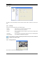
2.1.1.4 Thumbnail
If the Thumbnail Popup Auto Action option is selected, a thumbnail displays when an event
occurs. Double clicking on the thumbnail connects you to the event control station.
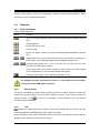
2.2
Toolbars
Frequently used features have toolbar buttons for your convenience.
(Chart. Toolbar Icons)
Button
Function
Hides Unit Explorer.
Hides Event View.
Expands the Main View area to the full screen.
Runs the Search program.
Runs the Setup program.
Searches saved events by date, unit, and category.
Enables you to set various options.
Adds units, screen layout, and maps.
Enables you to edit settings for registered units, screen layouts, and maps.
Deletes a unit, screen layout, or map.
Saves the current monitoring screen as a screen layout.
Refreshes the Unit Tree: updates connection status and unit list.
Disconnects from all monitoring units or closes all map windows.
Places a specific map on top of multiple map windows in the Map mode.
Disconnects from a currently monitoring unit, or closes a map window.
Cascade map windows.
Aligns map windows as tiles.
~
Split the monitor screen into 1, 4, 9, 13, 16, 25, 36, 49, or 64 screens.
Displays the software version.
Directs you to www.samsungipolis.com.
17
User's Manual
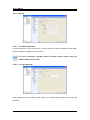
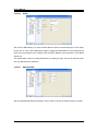
2.3
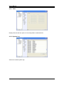
Site Mode
Site Mode enables you to register and manage multiple units. Units in Unit Explorer are
displayed under the Local Unit folder in your system for convenient registration. Via icons, you
can check unit models and their connection status.
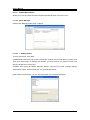
2.3.1
Creating & Deleting Folders
Right click on the My Unit folder, and then select "Add Folder" in the popup menu. When an
input window appears, enter a folder name, and then click "OK" to create the folder.
To delete a folder, right click on a folder, and then select "Delete Folder". Please remember if the
deleted folder contains units, the units are deleted at the same time.
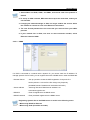
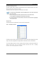
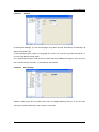
2.3.2
Registering & Deleting Units
To add a unit, drag and drop a unit from Local Unit to My Unit, or right click on a unit and then
click
"Add Unit". The Registration message window then appears. You can also click the
Add button on the toolbar. (The Add button may be inactive depending on the number of
maximum units that is allowed per license.)
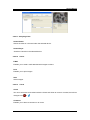
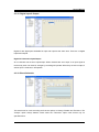
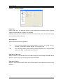
2.3.2.1 Registering Unit by Fixed IP / Domain Name
To register a unit through the "Add Unit" menu, enter the IP address and other information, and
then click "Search".
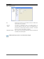
Address
Enter the IP address of a unit to be registered in My Unit.
Port
Enter the port number for the IP address above.
18
User's Manual
Name
Enter a meaningful name for the unit to help you easily recognize it.
User ID
Enter your administrator or user ID.
Password
Enter the password for the ID.
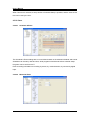
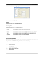
2.3.2.2 Registering Unit Registered in SWR
For units with dynamic IPs, register them in SWR (Samsung Registration Server) for effective
management.
MAC or Serial Number
Enter the MAC address or serial number of a unit that is registered on SWR.
For older models, enter the MAC address, and the serial number for newer models.
Port
Enter the port number for the IP address corresponding to the target unit.
Name
Enter a meaningful name for a target unit to help you easily recognize it.
User ID
Enter your administrator or user ID.
Password
Enter the password for the ID.
19
User's Manual
Searching by Group ID
Enter the group ID of a unit, and then click Search.
If the group ID is entered correctly, the product information of the unit is displayed at the bottom
of the window. If not, an error message like [Cannot find the unit.] appears.
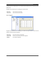
2.3.2.3 Registering Unit Registered on DDNS
This is to register a unit that is registered in DDNS.
To use the DDNS option, you must register the target product at www.samsungipolis.com.
DDNS Server
Enter the address of the DDNS server: ID
Enter the ID of the product that is registered with the DDNS server.
Name
Enter a meaningful name for a target unit to help you easily recognize it.
User ID
Enter your administrator or user ID.
Password
Enter the password for the ID.
2.3.2.4 Changing Unit Information
To change the information of a registered unit, right click on a unit, and then choose "Edit Unit".
A message window appears. You can also click the
"Edit" button on the toolbar. Port
Number and User Information can also be changed.
2.3.2.5 Deleting Units
To delete a registered unit, right click on the unit, and then choose "Delete Unit". You can also
click the
"Delete" button on the toolbar.
20
User's Manual
2.3.3
Renewing Unit Information
To refresh registered units and the unit list in the network, right click on the unit tree, and then
select "Refresh". Or select the "Refresh Site Tree" button on the toolbar.
2.3.4
Viewing Video
When a connection between the monitoring system and a unit is established, the video channel
of the unit is displayed in the unit tree. Selecting a video channel plays a live video of the
corresponding unit in the currently selected monitor within the Main View. To change the monitor,
drag and drop the channel icon to a different one.
To watch all channels of a unit, select the unit icon. The screen splits into several channels to
play the videos.
2.4
Screen Layout Mode
For effective management, you can register a group of channels as a screen layout. To activate
the Screen Layout mode, select the Screen Layout tab under Unit Explorer.
2.4.1
Registering & Deleting Screen Layouts
2.4.1.1 Saving Screen Layout
In the Site mode, you can save the current monitoring screen as a screen layout. To register a
screen layout, select a channel, and then select
"Save Screen Layout". When registering a
screen layout, information for the current monitoring screen—division, transfer speed, and
resolution—is registered at the same time.
2.4.1.2 Registering Using Menu
Right click on the desktop, and then choose "Add Screen Layout". The Registration message
window appears. You can also simply click
"Add" on the toolbar.
21
User's Manual
2.4.1.3 Changing Screen Layout Information
Right click on a screen layout, and then choose "Edit Screen Layout". A message window
appears. You can also simply click
"Edit" on the toolbar.
2.4.1.4 Deleting Screen Layout
Right click on a screen layout, and then choose "Delete Screen Layout". You can also simply
click
"Delete" on the toolbar.
2.4.2
Viewing Video
To play the videos of channels under a screen layout, select or drag and drop the screen layout.
The screen is split into the division of the screen layout and the videos play.
2.5
Map Mode
For convenient management, you can map devices such as channels, audio outputs, relay
outputs and sensors. To activate the Map mode, select the Map tab under Unit Explorer.
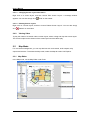
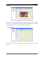
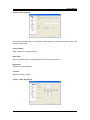
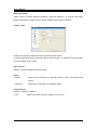
2.5.1
Map Editor
In the Map mode, run the Map Editor under Tools.
Map
Map Tree
Unit Tree
Registered Information
Toolbox
22
User's Manual
(Chart: Map Editor Toolbar)
Button
Function
Adds a map.
Saves map information.
2.5.1.1 Unit Tree
Displays available units and devices for mapping. Units can be
added only in the Monitor program.
2.5.1.2 Toolbox
To add a sub map or map link to a map, drag and drop
these icons to a map.
2.5.1.2.1 Sub Map
Enables you to create a sub map or related map under a higher map.
Adding Sub Maps
1. Open a map, and then drag and drop the Sub Map icon from the Toolbox to a location on the
map.
2. A message window prompts you to select a sub map. When Make New is selected, the editor
creates a new map, and then connects it as a sub map to the higher map. When Select Map
is selected, the editor connects a selected map as a sub map to the higher map.
3. To change an existing sub map, select the Sub Map icon on a map or the map tree, and then
edit the information in the Registered Information window.
23
User's Manual
4. To move to a higher map from a sub map, double click on
in the higher map, or click on
the X button in the window as shown in the picture below.
2.5.1.2.2
Map Link
Using Map Link, you can move among multiple maps with just one click.
Adding Map Links
1. Open a map, and then drag and drop the Map Link icon from the Toolbox to a location on the
map.
2. A message window prompts you to select a map to link. Select a map, and then press OK to
link the map.
3. To change an existing map link, select the Map Link icon on a map or the map tree, and then
edit the information under the Registered Information window.
2.5.1.3 Map Tree
Map Tree contains maps and devices that are registered in
the maps. Selecting an item in the tree displays editable
information of the item in the Registered Information window.
24
User's Manual
2.5.1.4 Registered Information
Enables editing the information of an item that is selected in
the map tree.
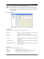
(Chart: Registered Information Available for Map Tree Icons)
Icon
Type
Registered Information
Folder
Does not show in the Registered Information window.
Map
The map name
Sub Map
The map name and layout
Map Link
2.5.1.4.1
The link name and target map
Channel
Does not show in the Registered Information window.
Sensor
Does not show in the Registered Information window.
Relay
Does not show in the Registered Information window.
Mike
Does not show in the Registered Information window.
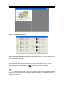
Layout Map
When a sub map is added, its higher map displays the Sub Map icon. To view the sub map,
click the icon; it opens in a new window. To view the all sub maps of a map, open Properties,
and then change the layout size of the maps.
Layout sizes are available from 1 x 1 to 8 x 8. When a size is
selected, a guideline is displayed. Each tile can contain only
one map; devices or map links cannot be added.
When a layout size is selected and a higher map is open in the Monitor program, the screen
displays the map as the example picture below.
If a sub map is not available, a layout tile displays
map.
25
. To enlarge a map, double click on the
User's Manual
2.5.1.5 Registering User Icons
You can add customized images for map icons: Channel, Mike, Relay, and Sensor. Supported
image formats are JPEG, GIF, and BMP. To add a customized icon, go to "Tools > Register User
Icon" under the Edit Map menu.
2.5.1.6 Adding Maps
At the main menu, click
. Select a map image, and then drag and drop it to the unit tree.
When the map is successfully added, click
, and then enter a name for the map.
You can change the direction of each device. To change to Rotation mode, double
click on a device placed on a map icon, and then rotate the cursor while holding down
the left button on the mouse. After changing the direction, double click on the device or click on
a different icon to finish.
26
User's Manual
2.5.1.7 Editing Maps
On the map tree on the right side, double click on a map to
open. If you want to change only the name of a map, right
click on a map in the map tree, and then rename the map in
the Properties window.
2.5.1.8 Deleting Maps
In the map tree, right click on a map, and then select Delete in the popup menu.
2.5.2
Viewing Map
Select a map in the map tree, then the map window opens.
2.5.3
Controlling Mapped Devices
2.5.3.1 Viewing Videos
Select a channel in the map tree, or the Channel icon in the Map window. Then the live video
monitor appears.
27
User's Manual
2.5.3.2 Sensor
The Sensor icon on a map starts blinking if a sensor on the map is activated.
2.5.3.3 Relay Out
The Relay icon on a map starts blinking if the relay output has been turned on in the map.
To turn on or off the relay output, click on the Relay icon on the map screen.
2.5.3.4 Mike
You can transmit audio by clicking the Mike icon on the map tree, or opening a map and then
clicking the Mike icon on the map.
2.5.4
Aligning Map Windows
If multiple map windows are open, you can align them by clicking the
Cascade Windows or
Align as Tiles option. To place a specific map on top of the map windows, click
.
2.5.5
Switching Map
The
button on the toolbar toggles when used. When activated, it opens new windows to
navigate between opened maps or opens a new map. When it is disabled, maps are aligned
next to each other, and you can navigate between maps by using the
and
buttons on
the toolbar.
2.6
2.6.1
Monitor Screen
Screen Interface
The caption Title Area is located at the top of the screen. This area contains the name of units
and channels, and buttons to control the recording, PTZ, and audio options. Time and event
information is displayed in the video area.
28
User's Manual
(Chart. Monitor Menu Buttons)
Button
Function
Saves video. (Maximum length: 10 min, re4 file)
Performs PTZ operations.
Turns audio on or off.
Disconnects from the current monitor. (Close the current monitor.)
2.6.2
Split Screen
You can split the monitor screen into 1, 4, 9, 13, 16, 25, 36, 49, or 64 screens.
2.6.3
Full Screen
To expand the Main View window to full screen, click
in the Tools menu. To return to
normal view, press "Esc".
2.6.4
Switching Screens
To switch to a new monitor screen from the current screen, left click on the current screen, and
then drag and drop it to a new screen.
2.6.5
Caption Information
To check and change a caption option, select the option under "Caption" in the Monitor popup
menu.
The caption options include Unit Name, Channel Number, Channel Name, Time, Event, and
Speed.
2.6.6
Video Transfer Speed
You can adjust the video transfer speed under "Transfer Speed" in the Monitor popup menu.
Only
the
SVR-1630,
SNP-1000/1000A/3300/3300A,
100/400, and SNC-550 support this option.
29
SNS-
User's Manual
2.6.7
Video Resolution
When Auto is selected, the program automatically adjusts the
resolution of the videos to the monitoring window size. When a
specific resolution is selected, the program plays videos at the
selected resolution regardless of the monitoring window size.
Only
the
SVR-1630,
SNP-1000/1000A/3300/3300A,
SNS-
100/400, and SNC-550 support this option.
2.6.8
Streaming
When monitoring a model that supports MPEG4 streaming, a
streaming menu appears in the Monitor popup menu.
When Auto is selected, the program requests the unit with an
optimal resolution for the monitoring window size and system
performance. Then the unit streams the video at a resolution
closest to the requested resolution. When a specific resolution is
selected, the program requests that resolution from the unit
regardless of the monitoring window size or system performance.
Only the SVR-1645/1660/1680/3200/960/945 models support this
option.
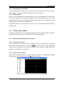
When monitoring MPEG4 streaming videos with SNM-128P, the number of
channels per resolution is as listed below.
(*Streaming Speed: 30 fps)
Based on this chart, SNM-128P can monitor 1 MPEG
streaming video at full-size resolution at 60 fps. When 3 or
more videos of the full-size resolution are selected, it displays
one per second. SNM-128P also displays one per second if
the monitoring system is overloaded by other applications.
2.6.9
Event
When movement is detected, the
When a sensor is activated, the
icon appears on the video.
icon appears along with the sensor number.
30
User's Manual
2.6.10 Saving Images
2.6.10.1 Saving Videos
Select "Start Recording" in the Monitor popup menu, or click the
recording button; the
recording time is recorded. The maximum length of a video is 10 minutes. To select a drive to
save videos, go to Tools > Options and select the Recording tab.
2.6.10.2 Saving Still Images
In the Monitor popup menu, select "Save Image" to save the current screen as a bmp, jpg, or
eye-formatted file. Eye-formatted files are viewable using Internet Explorer. To select the Auto
Save feature, image file formats, and a drive to save images, go to Tools > Options > Recording
(tab) > Save Image (heading). (If Manual Save is selected, a message window asking to select
a file format and filename appears upon selecting "Save Image".)
2.6.11 PTZ Control
2.6.11.1 Pan/Tilt Control
Select the "PTZ" menu in the popup menu, or click
. When crosshairs appear in the center of
the screen, use the mouse to perform the Pan and Tilt operations; click on the left or right side
of the cross to pan, and the upper or lower side to tilt. The farther you click from the center, the
faster the Pan and Tilt operations perform.
2.6.11.2 Zoom/Focus Control
To show the Zoom and Focus window, move your mouse to the left or right edge of the screen.
2.6.11.3 Moving to Preset
If preset locations are available, "Move to Preset" appears in the popup menu. Selecting a
preset under the Move to Preset menu moves the screen to the selected preset location.
31
User's Manual
2.6.11.4 Subsidiary Functions
If preset locations are available, "Subsidiary Functions" appears in the popup menu. Selecting a
subsidiary function commands the camera of a selected preset location to perform the
corresponding operation.
Only the SVR-1645/1660/1680/3200/960/945 models support this option.
2.6.12 Audio Control
If a channel supports the audio feature, "Listen to Audio" appears in the popup menu, or the
menu icon is activated. The default audio mode is muted. To listen to audio, select "Listen to
Audio" in the popup menu or the menu icon; you can unmute, adjust the audio volume, and mix
audio from multiple channels.
2.6.13 Buffering
Use Buffering to play a video smoothly when its transfer quality decreases at the full frame rate.
2.6.14 Closing All Monitors
closes the current video and map monitoring windows at once when clicked. In the Map
mode, this button closes all map windows.
2.6.15 Event Log
Events reported from registered units are listed at the bottom of the Control Center window.
2.6.16 Status & Action
Displays the real-time information of events occurring in registered units.
The buttons on the upper left side of the window toggle. When toggled (
), the selected
information is retained in the display area regardless how many events are logged.
(Chart: Event Icons)
Button
Function
Detect Movement
,
Sensor
32
User's Manual
Button
Function
,
Relay
,
Detected or Lost Video
Input Text
Authorization Failure
Change Settings
You can sort events by the unit and category.
(Chart: Event Toolbar)
Button
Function
Fix Log: retains a selected log in the display area.
Check Log
Comment: enables you to leave a comment in the log list.
Instant Viewer
Instant Player
Details
Action
Alarm Control Station
Search Event
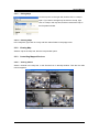
2.6.17 Viewing Videos
Double clicking on an event log starts monitoring the event channel. When Motion Detection is
selected, only the MD channels are displayed on the monitoring screen. Sensor and Relay
display the all channels of the event unit in split screens.
When a channel that is already in display is selected, the screen focus changes to the monitor
of the corresponding unit.
In the Map mode, the monitoring window pops up.
2.6.18 Processing Events
Unchecked events are highlighted in bold.
The administrator can double click, or click
(Check) or
(Comment) to check and
leave comments on events.
2.6.19 Instant Viewer
Select an event log, and then click
(Instant Viewer) to run the single-channel viewer and
watch a live video.
33
User's Manual
If a selected log is not a 1-channel event, this button is grayed out and you cannot run Instant
Viewer.
2.6.20 Instant Player
Select an event log, and then click
(Instant Player) to run the playback program and
search videos that are recorded in the DVR of the event unit.
If the event unit is not equipped with a HDD, this button is grayed out, and you cannot run
Instant Player.
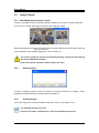
2.6.21 Alarm Control Station
The Alarm Control Station window as shown below enables you to take countermeasures for a
selected event. To open the window, select an event log and then click
Station), or double click the thumbnail.
34
(Alarm Control
User's Manual
2.6.21.1 Analyzing Video
Instant Viewer
Shows the video of a channel under the selected device.
Instant Player
Searches channels in the selected device.
2.6.21.2 Action
E-Mail
Enables you to send e-mails attached with images to others.
Print
Enables you to print images.
Save
Saves images.
2.6.21.3 Check
Check
You can mark events as checked under the Check tab. When an event is checked, the left icon
changes from
to
.
Comment
Enables you to leave a comment on an event.
35
User's Manual
2.7
Status & Action
To open Status & Action, select the tab in Event View.
2.7.1
Status & Action Information
Displays the current video channel and sensor of units registered in My Unit.
You can perform various actions such as Relay Out and Audio Out under this tab. To perform an
action, select an icon. Audio Out enables you to send audio to multiple units at a time.
This tab also displays the current time of each unit.
(Chart: Status & Action Icon)
Button
,
Function
,
Motion Detection, Activate Channel, Lost video, Disable Channel
,
Input Sensor
,
,
Relay Output
,
Mike On/Off
,
,
Displays the HDD status (In the order listed)
,
Record Disabled
Recording
,
Event alert; As scheduled
,
Always on
Always off
2.7.2
Viewing Videos
Double clicking on an event log starts monitoring the entire channels of the unit. The monitoring
screen is splint into the number of channels. In Map mode, the monitoring window pops up.
2.7.3
Selecting Different Event Alert Types by Unit
You can set up a different event alert method for each unit by using the Event Notice column at
the far right side. There are three different alert types: Always on, Always off, and As scheduled.
The default parameter changes from Always on to As scheduled and Always off each time the
option is clicked. You can set up an event alert type and edit the notice schedule at Tools >
Options > Event Notice (tab).
36
User's Manual
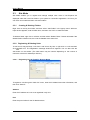
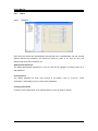
2.8
Searching Event
The SNM-128P saves all event logs and allows you to search them by time, unit, and category.
To search, click
(Event Search Utility) on the toolbar.
Enter search conditions, and then click "Search". The event log search results are displayed.
The screen displayed in the window is identical to the one in the Monitor program and allows
you to open the Alarm Control Station window.
When a searchable unit is selected, the Search button is activated.
You can delete all logs or a specific block of event logs under the Advanced tab in the Event Log
Utility window.
37
User's Manual
2.9
User Settings
User Settings are to manage program users. Upon installation, the program creates an
administrator ID with all permissions. The administrator ID cannot be deleted.
To manage users, select the User Settings menu under the Administrator menu.
To add a user, click "Add".
Available permissions are Monitor, Search, Setup Program. When only Monitor is selected, the
user cannot modify program information such as units, screen layouts, maps, and user settings.
2.10
Changing Passwords
Allows you to change the password for user IDs. To change a password, select the Change
Password menu under the Administrator menu.
Enter the current password, a new password, confirm the new password, and then click OK to
apply the change.
2.11
Setting Up Options
Allows you to set up various options. To set up options, go to Tools > Options.
38
User's Manual
2.11.1
Display
Monitor Viewer Mode
The "Full" mode shows a video in full screen mode.
The "Fit to Ratio" mode shows a video fit to the original screen ratio of the video.
The "Caption Included" mode displays the Caption area and a video fit to the original screen
ratio of the video.
DirectX
When the Use DirectX box is checked, video is rendered with DirectDraw. The video graphic
quality varies depending on your graphic card performance.
Deinterlacing
Deinterlaces video: Can be used only with D1 video settings.
Color Space
An MPEG4 streaming video at full-size resolution can be played at 120fps in YUV mode and
60fps in RGB mode. When more than 4 full-size YUV videos or 2 full-size RGB videos are
selected, the program displays one per second. SNM-128P also displays one per second if the
monitoring system is overloaded by other applications.
The monitoring performance of the program may vary depending on the
performance of your system: CPU, graphic card, and memory.
Low bandwidth mode
Improves the monitoring performance in a low-speed network environment.
39
User's Manual
Caption
Enables you to set up Caption Information, View Mode, and Map Options in Monitor View. You
can hide or unhide Unit Name, Channel Number, Channel Name, Time, Event, and Transfer
Speed displayed in the caption area.
The font color and size for the caption text are also customizable.
Map Options
Selecting Unit Name shows a unit name next to a device name registered on a map.
2.11.2 Recording
2.11.2.1 Recording
Selecting Quick Recording Directory (Quick Save)
Select a drive to save quick-recorded video files.
When a drive is selected, the CCQuickRecording folder is created in the directory. Under the
folder, video files are saved as ref4 files, named by the recording date, under sub folders named
by the unit name_folder name.
Selecting Event Recording Directory (Auto Action)
This option is to select a drive for the "Recording" option in the Auto Action menu. When a drive
is selected, auto-recorded video files are saved as ref4 files, named by the recording date,
under sub folders named by the unit name_folder name within the CCEventRecording folder in
the drive.
2.11.2.2 Save Image
Select a drive to auto-save images.
Check on or off on the Name files automatically box, and select an image file format. (BMP,
40
User's Manual
Wavelet (EYE), JPEG)
When a drive is selected, the CCImage folder is created in the directory. Under the folder, image
files are saved as bmp, jpg, or eye files, named by the saved date, under sub folders named by
the unit name_folder name.
Retention
You can select a retention period for saved files. When the period expires, saved files are
automatically deleted.
Retention dates can be between 1 and 180 days. The default period is 5 days.
2.11.2.3 Quick Save Recording Length
Select the maximum length of video files recorded by the "Start Recording" option in the Monitor
popup menu.
Available lengths are from 1 to 10 minutes.
2.11.3 Event Alert
2.11.3.1 Alarm
When the Alarm box is checked, the program plays a sound a selected number of times for a
selected duration each time an event is logged.
2.11.3.2 Action Duration
Select the running time of event videos.
2.11.3.3 Sound Settings
To use the SNM-128P default sound, click the Default Sound button. To use a customized
sound, click Custom Sound and then select a sound file.
Supported audio file formats are wav and mid.
41
User's Manual
2.11.3.4 Display on Video Monitor
Check or uncheck the box to highlight an event area on the video in red.
2.11.3.5 Event Log
Check on or off to display the Event icon in event logs. Even if the box is not checked, important
events such as failed authorization and hardware failures are always displayed.
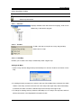
2.11.3.6 Event Alert Schedule
When the Setup button is clicked, the Event Alert Schedule appears, allowing you to edit the
event alert schedule of a unit. Select a unit, and then turn on (blue) or off (gray) an alert type per
hour. To apply the current schedule to the entire units, press the Apply to All Units button.
Pressing All turns on all alert types per hour, and Remove turns off all alert types per hour.
Keeping the event alert schedule on at all times may overload the system
database with a large number of event logs. Too many event logs can cause
system malfunctions. Please make sure to remove event logs using the Event
Search Utility on a regular basis.
2.11.4 Monitor Layout Manager
The SNM-128P supports up to 6 monitors. You can set up each monitor with different settings.
Upon the installation and when a new user is logged in, the program activates only 1 monitor. To
set up multiple monitors, go to "Options > Monitor Layout Manager".
42
User's Manual
A number of the basic monitor templates
are provided according to the number of
available monitors.
The preview screen is provided per
monitor after it is selected and set up. The
OK button is provided to confirm the
changed settings.
In this section, you can set up
detailed settings of a monitor.
These navigation buttons are activated when 4 or
more monitors are selected.
The Monitor Layout Manager window provides templates depending on the number of available
monitors. For instance, if your system has 2 monitors, you can select a template with only 2
monitors and the
and
buttons are grayed out.
Settings
Description
Site/Screen Layout/Map
Adds the Site, Screen Layout, and Map tree modes to the
selected monitor; displays the Monitor window in the Site and
Screen Layout mode, and the Map window in the Map mode.
Site/Screen Layout
Adds the Site and Screen Layout tree modes; displays the
Monitor window only.
Map
Adds the Map tree mode only; displays the Map window only
without the Site and Screen Layout tree modes and the Monitor
window.
Log
Select if the monitor is used only to log events or perform the
Status & Action feature. When neither Event Log or Status &
Action is not selected under Log, the monitor becomes disabled
as if it is not physically selected.
Event Log
Displays event logs in real time.
Status & Action
Displays the status of units and Status & Action feature.
Monitor Window
Select if the monitor is used only to watch video; this exclusive
option cannot be used in conjunction with any other options
listed above.
43
User's Manual
2.11.5 Instant Auto Action
Allows you to set up actions that are activated automatically when an event occurs.
2.11.5.1 Action Manager
Select Action Manager under Tools > Options.
2.11.5.1.1 Adding Actions
To add a new action, click "New".
Available auto actions are Pop up event, Show latch window, Send e-mail, Move to preset, Save
video, and Save image. To activate auto actions, you must select a unit, types of events, and
specific conditions for each action.
Available event types are Motion detection, Sensor, Input text, No video, Change settings,
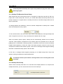
Authorization failure, Disconnected from unit, and Hardware error.
When creating a new action, you can name the action for convenient reference.
44
User's Manual
2.11.5.1.2 Changing Action Information
Action information can be changed, but the type cannot be changed.
2.11.5.1.3 Deleting Actions
To delete an action, select an action and then click "Delete".
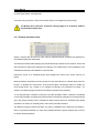
2.11.5.1.4 Action List
The "Select Action" section lists brief information for the current actions. To disable an action,
uncheck the box next to the action. (
>
)
2.11.5.1.5 Action Description
The "Action Description" section displays conditions to activate an action. To change the
detailed settings, click on an underlined area.
(Chart: Action Settings)
Action
Action Description Example
Show latch window
When an event occurs in a unit { all units },
show the latch window.
Send e-mail
When an event occurs in a unit { all units },
send an e-mail to { recipient name }
once every { intervals } only if it is { scheduled }.
Move to preset
When an event occurs in a unit { all units },
{ move to the unit, move to the event channel, move from the
current channel to the preset, move to the preset}
for { duration }, only if it is { scheduled }.
Recording
When an event occurs in a unit { all units },
record the video of the unit { of the unit channel }
({Resolution: CIF, 5fps, Duration: 5 seconds})
only if it is { scheduled }.
Save image
When an event occurs in a unit { all units },
save the image of the unit { of the unit channel }
({Format: BMP, Resolution: CIF, 1fps, Duration: 1 second})
only if it is { scheduled }.
Audio Play
When an event occurs in a unit { all units },
play { the audio unit }
only if it is { scheduled }.
Pop up thumbnail
When an event occurs in a unit { all units },
display the thumbnail image of { the channel }
only if it is { scheduled }.
45
User's Manual
2.11.5.1.6 General Action Settings
To activate actions, you must select units and events. To set up multiple units with multiple
events, select a group of units in the unit tree, and then click on events listed on the right side.
Among the available events, Motion detection and Sensor can be set up per channel. The
available number of channels is equal to the channels supported by a selected unit.
Select the duration of an action. (Unit: seconds)
You can schedule actions. To set up an action schedule, select a unit in the left unit tree, and
then select actions for the course of 24 hours. For more information about setting up schedules,
please refer to section 2.11.3.6, Event Alert Schedule.
46
User's Manual
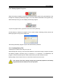
2.11.5.2 Latch Window
Show or hide a latch window when an event occurs. The latch window is to report the status of
an event and describe countermeasures taken for the event. It is usually used to report critical
errors such as a sudden disconnection and hardware errors. The countermeasure description is
saved and searchable through the Search Utility at Tools > Error.
2.11.5.3 Sending E-Mail
Send an e-mail to a selected e-mail address when an event occurs. You can add a message to
the e-mail.
Select an e-mail address and then write a message in the blank box.
2.11.5.4 Move to Preset
When an event occurs, move the camera to a selected preset.
Select a unit, a channel, and then a preset number.
2.11.5.5 Recording
When an event occurs, record the video for a set duration. The video file is saved in a directory
that is selected under the "Recording" tab in the "Options" window.
47
User's Manual
To save video from a unit with an event, select all units. To save the video of a different unit,
select a single unit. Selecting Same Unit and checking Related Channel saves the video of an
event channel. Sensor saves events of the channel that is selected under "Options > Event
Alert > Event Alert Schedule," but does not save non-video events. To select a different
channel, select "Select Channel" below Related Channel and then select a channel.
Select a resolution (QCIF, CIF, Full(D1)), transfer speed, recording duration, and file interval to
save video files.
When the Auto Recording option is selected for multiple units, the recording
settings--resolution, transfer speed, etc.--are automatically selected according to
the settings of the units.
Video files are saved in a hard drive that is selected under "Options > Recording," under the
CCEventRecording folder. Saved video files are re4 files named by the recording date in sub
folders named by unit name.
Available transfer speeds are from 1 to 30 fps.
Available recording durations are from 5 to 180 seconds, and file intervals are 5 to 3600
seconds.
2.11.5.6 Save Image
When an event occurs, save the image of the selected channel. The image file is saved at
"CCImage\SiteName_ChannelName" in a hard drive that is selected under "Options >
Recording (tab)".
48
User's Manual
Available image file formats are BMP and Wavelet, and resolutions are QCIF, CIF, and Full(D1).
Wavelet files are saved as eye files that can be viewed in web browser.
(Eye files can be converted to bmp or jpg files using a file converter program.)
Available frames are from 1 frame/5 seconds to 3 fps, and durations are from 1 to 180 seconds.
1 frame/5 seconds saves one image every 5 seconds, while 3fps saves 3 images
every second.
2.11.5.7 Play Audio
When an event occurs, send the selected audio file to a selected unit.
To play audio from a selected unit, select an audio file and a duration or the Repeat option.
plays the audio file.
Supported audio file types are PCM 8kHz, 16Bit, and Mono. Audio files other
than the listed types cannot be played.
2.11.5.8 Pop up thumbnail
When an event occurs, this activates a thumbnail for the event.
49
User's Manual
2.12
Searching Error Log
When a critical error occurs that requires the operator to take immediate action, or when the
monitoring system cannot connect to a unit, or an HDD is broken, the following latch window
appears asking to enter information for steps taken to correct the problem.
The operator must write a description of actions taken and then enter the password of his SNM128P account.
This information for errors is searchable through the Search Utility at Tools > Error.
50
User's Manual
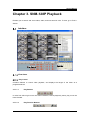
Chapter 3. SNM-128P Playback
Enables you to search and view videos, audio, and text saved in units. To view, go to Tools >
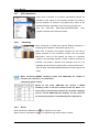
Search.
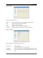
Interface
Log View
HDD Status View
Channel View
Calendar
Play Control
View Areas
3.1.1.1 Play Control
Contains features to control video playback, and displays the length of the video as a
progress/seek bar.
3.1.1.1.1
Play Buttons
In order from left to right: move one frame backward, reverse playback, pause, play, move one
frame forward.
3.1.1.1.2
Play Function Buttons
51
User's Manual
In order from left to right: play event only, accelerated playback, listen to audio, text list, show
the timeline only for a selected channel, and time line interval.
3.1.1.2 Log View
Shows the log of a selected area by category.
To open Log View in a popup, double click on the Log View area. Closing the popup window
restores the original Log View.
3.1.1.3 HDD Status View
Shows used and free space in the HDD of a selected unit along with the recording date and
time.
3.1.1.4 Channel View
Allows you to play and watch the video of a selected channel.
3.1.1.5 Calendar
Click on dates to change the search period.
Toolbar
(Chart: Play Toolbar)
Button
Function
Opens a file or unit.
Disconnects from the current unit.
You can split the Channel view screen into a number of channels for a selected
unit, if the channels are more than the current number of split screens; this button
is to undo the current split screens.
You can split the Channel view screen into a number of channels for a selected
unit, if the channels are more than the current number of split screens; this button
is to redo a number of previous split screens.
Displays a message window to adjust the screen.
Saves the video of the currently selected monitor.
Prints the video of the currently selected monitor.
~
Split the monitor screen into 1, 4, 9, or 16 screens; enables you to search a
maximum of 16 channels.
Searches text.
Searches videos by motion.
Searches thumbnails.
Displays the software version.
52
User's Manual
3.2
Click
Opening Unit & Backup File
, or go to File > Open. My Unit tree appears, displaying only units that are equipped
with hard disks. To search a unit, select a unit and then click "OK".
To search a backup file, click the "Open File" button and then select a file.
When a unit is opened for the first time, the program searches the data based on the latest date
and time; the search timeline is automatically adjusted based on hours saved for the latest date.
(For instance, if data was saved for 4 hours for the latest date, the program searches the data
for a 6 hour duration.)
3.3
Search
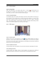
3.3.1 Image Information Display
The image of each channel displays a different depth of color depending on the number of
saved frames; the color becomes darker as the saving speed is higher. The red block indicates
the image of events such as motion detection and sensor. The orange blocks before and after a
red block indicate videos recorded before and after an event occurs. The bright lime green block
indicates a text area.
Based on a 24 hour duration, the length of the bottom scroll bar changes depending on the
length of a searched area.
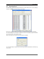
3.3.2 Changing Search Timeline
To change the search timeline, click the button on the upper right side of Play View. There are 6
timeline length options available: 10 minutes, 30 minutes, 1 hour, 3 hours, 6 hours, 12 hours,
and 24 hours.
53
User's Manual
3.3.3 Selecting Channels
A number of the channel buttons can be activated depending on the number of available
channels per unit. To select a channel, click the corresponding button.
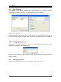
3.3.4 Calendar Search
You can pause a video, and move the search timeline to a specific date on the calendar. To
move, click a date on the calendar, or enter a date and then click
.
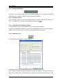
3.3.5 Log Information Display & Search
Log View displays the list of logs available within the current search timeline.
The log list includes logs available only in the currently searched channel, and can be sorted by
category. To move to a specific hour, click on a corresponding log in the log list.
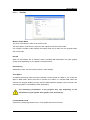
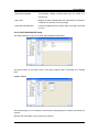
3.3.6 Searching Text
You can search text available in a specific timeline.
The SNR-64B activates a combo box prompting you to select a unit to search.
Enter a timeline, keyword, and filter conditions, and then click "Search". Text search results are
listed in the results section. While searching, a progress bar is displayed at the bottom of the
54
User's Manual
window. When finished, the window lists the results filtered by keyword.
Clicking "Save" saves the text search results as a text file.
To move to a text area, double click on a search result.
While searching, other search features cannot be used: searching motion detection area, play
video, or moving to a different point of time.
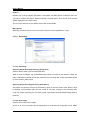
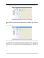
3.3.7 Smart Search
Enables you to search motion-detection videos within a specific timeline.
Only the SVR-3200/1680/1660/1645/960/945 models support this option.
The SNR-128B activates a combo box prompting you to select a unit to search.
Select a channel, area, timeline, and video interval, and then click "Search". Selecting "Search
motion detection image only" searches only videos that have detected actual movement. (The
Motion Detection option can be set up in the Setup program.) Selecting "Inspect All Images"
searches all videos in a selected timeline that contain any motion detection results. Selecting
"Inspect per Time Interval (Sec)" searches motion-detection videos for selected time intervals
within a selected timeline.
When searched, snapshots of searched images are listed that show the beginning of a
movement event. While searching, the progress bar is displayed at the bottom of the window.
When finished, search result images are displayed.
Clicking on a snapshot displays the actual image on the upper right side of the screen. Double
clicking on a snapshot moves the play view to the point of time that the snap shot was taken.
While searching, other search features cannot be used: searching motion detection area, play
video, or moving to a different point of time.
55
User's Manual
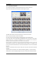
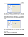
3.3.8 Searching Thumbnails
You can search thumbnails in a specific timeline by day, hour, minute, and second.
Only the SVR-3200/1680/1660/1645/960/945 models support this option.
The SNM-128P activates a combo box prompting you to select a unit to search.
Enter a channel and timeline, and then click "Search".
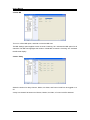
In the [ Day ] area, daily saved images are displayed based on the selected timeline.
In the [ Hour ] area, hourly saved images are displayed per day. At the bottom of the window,
images saved every 10 minutes are displayed per hour. To adjust the time intervals of
thumbnails, select an interval and then click "Search" in the combo box.
Double clicking on a thumbnail in the [ Day ] area searches thumbnails by the hour, minute, and
second based on the date of the selected thumbnail. Double clicking on a thumbnail in the
[ Hour ] area searches thumbnails by the minute and second based on the time of the selected
thumbnail.
Clicking on a thumbnail moves the screen of Play View to the point in time that the thumbnail
was taken.
To play the video of a thumbnail, click < (Reverse Playback), [](Pause), or > (Move Forward).
Clicking "Move" moves the Playback program to the point in time that the thumbnail was taken.
56
User's Manual
Clicking "Smart Search" opens the Smart Search window to search motion-detection videos
based on the time of a selected thumbnail.
3.4
Playback
3.4.1 Playback Buttons
(Chart: Playback Buttons)
Button
Function
Moves one image backward. (Only SVR-3200/1680/1660/1645/960/945 support
this.)
reverse playback.
Pauses the current video.
Moves forward.
Moves one image forward. (Only SVR-3200/1680/1660/1645/960/945 support
this.)
/
Toggle buttons; the first one plays the entire video, and the later one plays only
event videos. (Only SVR-3200/1680/1660/1645/960/945 support this.)
~
Supported play speeds: 0.5x, 1x, 2x, 4x, 8x, 16x, 24x, 32x, 64x, and All. In the
All mode, the entire video is played.
These options are to play video at faster or slower speed, but actual speeds
may vary depending on your network bandwidth and speed.
Shows the video status of all or selected channels in a unit.
The Playback program may display the time of a video differently if the settings
of the DVR and the SNM-128P are different.
3.4.2
Playing Audio
This option is available only when a video is playing forward at 1x speed. It plays the audio of all
videos that are being played. To turn off audio, adjust the volume, or play only the audio of a
selected channel, click
. If audio is not available in some channels, the One Channel
checkbox becomes disabled.
3.4.3
Text
displays the Text window when clicked. It shows text received from the server. Only the
SVR-3200/1680/1660/1645/960/945 models support this option.
Double clicking on text moves the Playback screen to the point in time that the text was entered.
Clicking "Save" saves the current text as a text file.
57
User's Manual
3.5
Image Control
3.5.1 Zoom/Brightness/Contrast Control
To open a message window to adjust the quality of images, go to Image > Screen Adjustment.
To zoom in on a certain area, drag to select the area using the mouse.
adjusts the brightness, and
the contrast. Clicking on the left button resets the
current settings to their defaults. (Brightness: 1000, Contrast: 0)
You cannot change the quality of an image by pausing a video and then opening
the Screen Adjustment window;
please first open the window, and then pause the video.
3.5.2
Saving Images
To open a message window to save the video of a selected monitor, go to Image > Save.
Images are saved as bitmaps, including memos and captions.
3.5.3
Printing Images
To print the image from a selected monitor along with a memo, go to Image > Print.
The standard printing size is A4.
A memo can contain a maximum of 7 lines with 45 characters per line.
58
User's Manual
3.6
Backup Feature
opens Backup Utility.
Available formats for backup files are rec and avi. When rec is selected, the left window is
displayed, and the right window when avi is selected.
The re4 option enables you to back up all channels simultaneously while avi allows only one
channel at a time.
You can back up files per unit. To back up, select necessary information including a timeline
(date and time), channel, incremental file size, filename, and password, and then click "Start".
The password option is not available for avi backup.
3.7
Backup Log
backs up only the text information of logs as an excel file.
To back up, enter the necessary information including a timeline (date and time), channel, and
filename, and then click "Start".
59
User's Manual
3.8
Setting Up Options
3.8.1 Captions
Hide or unhide Unit Name, Channel Name, Time, Event
Caption in the Caption window. Unit Name is available only in
the SNR-64B. You can also change the color of the caption
font.
3.8.2 Spilt Screen Auto Control
Under the Screen tab, a checkbox is provided to automatically
split the monitor screen for several channels. A maximum of 16
split screens can be displayed simultaneously.
Checking on Deinterlacing applies the Deinterlace mode to all
videos.
The supported color spaces are RGB and YUV.
3.9
Simple Mode Playback
The Playback program runs in Simple mode when it is opened from a map.
The length of the bar at the bottom of the Playback screen changes depending on the video
length. To play video from a different channel recorded in the same timeline, drag and drop the
channel from the map to the Playback window.
60
User's Manual
Chapter 4. SNM-128P Setup
The images included in the following guideline may contain a number of channels and menus
that differ depending on your product model.
This guideline applies only to the SVR-3200/1680/1660/1645/960/945/1630 models.
4.1
Program Login
(1) Click on the "SNM-128P Configuration Tool" icon on the desktop.
(2) Log in to the program.
Enter your ID and password, and then click OK.
The SNM-128P Setup program runs if the ID and password match.
The default ID is "Administrator", and the default password is "12345".
4.2
Interface
Site Tree
Menu
Settings Page
61
User's Manual
The main Configuration Tools screen is as shown in the picture above, consisting of Site Tree,
Menu, and the Settings page.
4.2.1
Site Tree
Units displayed in the site tree are the ones registered in My Unit in the SNM-128P Main View;
they cannot be added, deleted, or edited in Configuration Tools.
The unit list is synchronized to My Unit in the SNM-128P Monitor program on a regular basis. To
refresh the list immediately, click Refresh at the bottom of the window.
Clicking on a unit displays available settings menus in the Menu area and the system settings
page in the Settings page.
4.2.2
Menu
Menus in the Menu window vary depending on the product model. Clicking on a menu displays
the settings of the menu in the Settings page.
4.2.3
Settings Page
Changing settings parameters in the Settings page enables the "Apply" button at the bottom of
the window. Make your changes and then click the button to apply the changes.
Please remember that any changes made in the Settings page will not be saved unless the
"Apply" button is clicked.
If you do not click the "Apply" button and attempt to move to a different settings menu, a
message window will prompt you to apply the changes before navigating away.
62
User's Manual
4.3
Setup Guidelines
4.3.1
System Setup
4.3.1.1 System Setup
Displays the system information of a DVR. The Unit Name is displayed in blue and can be
double clicked to change it. To rename a unit, enter the new name and then click "Apply".
4.3.1.2 Importing & Exporting Settings
You can save all settings information for a DVR as a file (export settings), and apply the settings
to other DVRs using the saved file (import settings). .
This option is useful to apply the same settings to multiple DVRs, but can be used only if they
are in the same product family and have the same firmware version.
Only the SVR-3200/1680/1660/1645/960/945/1630 models support this option.
<Exporting Settings>
63
User's Manual
Clicking on "Export Settings" opens a window to save the settings information of a DVR as a file.
Enter a name for the exported file.
<Importing Settings>
Clicking on "Import Settings" opens the Import Wizard window. In the file list, select an exported
settings file saved as *.cci. The product type, hardware type, and firmware version of the
selected file are displayed. Check the information, and then click "Next".
Set whether the export and import devices are the same, the same model, or in the same
product range.
If they are the same device, the wizard program can import the settings immediately.
Enter your administrator password, and then click "OK" to import the settings.
64
User's Manual
When the settings are successfully imported, the "Completed" window appears, enabling the
"Exit" button.
Restart
Restarts a DVR.
Reset Settings
Resets the current settings to their factory defaults.
Change IP Address
Enables you to change the IP address of a DVR.
The Reset Settings option does not reset the date and time, network settings, or
video types (NTSC/PAL) of the monitoring system.
65
User's Manual
4.3.2
Screen
4.3.2.1 Video Channel Setup
Allows you to change the basic information, screen brightness, and contrast of a video channel.
The number on each tab indicates a video channel number: CH1, CH2, CH3, CH4 … CH16.
4.3.2.2 Channel Information
- Activate
: Turns a channel on or off.
- Channel Name
: Name a channel.
- Camera Type
: Displays the video type; displays automatically.
(NTSC/PAL)
- B/W Mode
: Check if the video output is black and white.
4.3.2.3 Image Adjustment
Enables you to optimize the brightness, contrast, and AGC of images.
Clicking the Brightness or Contrast button resets the settings to the default.
66
User's Manual
4.3.3
Date/Time
4.3.3.1 Date/Time
System Time
Displays the date and time on a DVR. This can be changed only in the Local Unit menu.
Standard Time Zone & Daylight Saving Time
Displays the current time zone of a DVR. Selecting a daylight saving time zone opens a window
to activate the DST option. When DST is turned on, the program applies the time settings in the
same way as Microsoft Windows does.
4.3.3.2 NTP Setup
NTP (Network Time Protocol) enables you to synchronize the time of all devices on a network.
- Mode
: Available modes are Server, User, and Bi-Support. When Server mode is
selected, the DVR becomes the time server. When User mode is selected, the
DVR receives the time information from a time server.
When the Bi-Support mode is selected, the DVR performs as both the time
server and a user.
- Refreshing : Select an interval to receive the time information from the time server if the
Interval
DVR is set to User mode.
(Available Intervals: 1/3/6/12/24hr)
- IP Type
: To receive the time information from an NTP server on the internet, select the
public IP. To receive the time information from an NTP server within the same
network, select the private IP.
- Private IP
: If the selected IP type is Private, enter the IP address of the NTP server.
67
User's Manual
4.3.4
Network
4.3.4.1 For Ethernet Networks
If using a dynamic IP, select "Use DHCP". If using a fixed IP, enter the IP address, subnet mask,
gateway address, and DNS server for the unit.
For more information regarding fixed IP settings, please inquire with your
network administrator or ISP.
4.3.4.2 For xDSL Networks
If the network line is xDSL (ADSL, HDSL, VDSL, etc.), select xDSL and then set up an ID and
password.
68
User's Manual
1. Some xDSLs are ADSL, HDSL, and VDSL, and can be used if the protocol is
PPPoE.
2. To set up an xDSL network, WRS must be set up at the same time, unless you
use fixed IPs.
3. Changing the network settings to xDSL no longer enables the servers within
the network to connect to ones in the Ethernet environment.
4. The user ID and password are the ones that you received from your xDSL
provider.
5. If your network line is xDSL, but uses an auto connection modem, select
Ethernet instead of xDSL.
4.3.4.3 DDNS
If a DVR is connected to a network with a dynamic IP, you cannot check the IP address. To
manage dynamic IPs for DVRs, you can register them with a DDNS Server under the DDNS tab.
- Renewal Period
: Set up a period to renew the SWR registration for dynamic IPs.
Set the period to 1 minute if the IPs change very frequently.
(Available Periods: Disable/1min/1hr/3hr/6hr/12hr/24hr)
- Server Address
: Samsung Techwin's DDNS server address is at
www.samsungipolis.com.
- DDNS ID
: Enter ID registered to the DDNS server.
- DDNS Password
: Enter password registered to the DDNS server.
Registering dynamic IPs to the DDNS server is useful in the following cases:
- When using DHCP for Ethernet
- When using xDSL (Fixed IPs excluded)
69
User's Manual
4.3.4.4 Setting Up Ports
Port
: Change a port number if you are unable to connect to a DVR due to
various reasons such as firewall.
- Time Out
: This option is to distinguish a client in an unstable network. If a
Period
connection between the DVR and a client is not established within a
set time limit, the DVR forcibly closes the connection. The default
period is 3 minutes. (Period Range: 0~3600sec)
- Bandwidth Throttling
: When checked, the web viewer data transfer speed of the SNM-128P
is throttled to the selected speed.
DVRs automatically connect to a new network when changed.
70
User's Manual
4.3.5
COM Port
In the COM Port page, you can set up the settings and device of each COM port. The number
of tabs changes according to the number of available COM Ports, and the name of each tab
indicates the COM port number.
4.3.5.1 Selecting Device for Serial Port
Supported devices for serial ports are PTZ, TP, Keyboard, and Text.
- PTZ
: Select to connect a PTZ. Selecting this menu opens the detailed settings at the
bottom of the widow, allowing you to select an appropriate PTZ device. To
move to the PTZ settings page directly, click "To Setup Screen".
- TP
: Select to use a serial port for TP. This is used to pass serial data from a serial
port to the network.
- Keyboard
: Select to connect a keyboard. Selecting this menu opens the detailed settings
at the bottom of the window, allowing you to select an appropriate keyboard.
- Text
: Select to connect a text device. To move to the Text settings page, and click
"Go".
71
User's Manual
4.3.6
PTZ
The label on each tab indicates a camera channel number. Select a channel to connect your
PTZ.
4.3.6.1 PTZ Setup
To use PTZ, you must select PTZ in the COM Port page.
- Activate
: Check the box to connect the channel to the PTZ.
- PTZ Port
: Select a serial port for the PTZ device.
- Address
: Enter the address of the PTZ device. The PTZ device settings value
is the address.
- PTZ Home
Time Out Period
: Set up a period to command the camera to move to a selected preset
if no movement is detected for the period.
If a PTZ device is already connected, you must first set up the device under the
"Channel" and "Device" tabs.
4.3.6.2 Setting Up Presets
Click "Preset" to open the Preset Settings window.
72
User's Manual
Recording & Deleting Presets
To record a preset, select a preset in the list and then move to a desired location in the video.
Enter the preset name, and then click "Apply".
To delete a preset, select a preset in the list and then click "Reset".
1. To activate the PTZ operation, open the popup menu in the video screen and
then select "PTZ".
2. After activating the PTZ option, place the cursor in the video screen;
a cross appears, enabling you to pan and tilt the camera.
3. To activate the Zoom or Focus menus, move the cursor to the left or right edge
of the video screen.
Using Presets
To activate and use a recorded preset, check a preset in the preset list.
4.3.6.3 Auxiliary Functions
PTZ Devices offer a variety of auxiliary functions (e.g.: wiper control when equipped with a wiper,
or light control when equipped with a light) aside from their basic functions: Pan/Tilt/Zoom.
To use the auxiliary functions, click the "Auxiliary" button and open a window that contains 16
auxiliary function boxes. Set up the auxiliary functions, and then click "PTZ" > "Auxiliary
Function" in the screen popup menu to use them.
73
User's Manual
4.3.7
4.3.7.1
Users
Account
DVR users are divided into administrators and general users. Administrators can use all DVR
features without any limitations. The maximum number of users is 10. They can only use
features that they have permissions for.
Administrator Password
The default administrator password is "11111111" and can be changed. To change, enter an 8digit password.
User Password
The default password for each user account is as follows: user1 is "11111111", user2
"22222222", and similarly on up to user10 with “00000000”.
Changing Passwords
As shown in the image below, click Change P/W for a user you want to change.
74
User's Manual
4.3.7.2
Permissions
Normal user permissions are Mic, PTZ, Relay, Search, Quick Save, Back Up, Play Audio, Menu,
Power On/Off, View Video by Channel. The default user accounts—user1, user2, on up to
user10—have permissions only to view video by channel, quick save, back up, and play audio.
4.3.8
IP Filtering
This IP filtering lets you to allow or deny access to DVRs for specified IP address ranges.
When Allow is selected, only the IP ranges added in the list are allowed to access the DVRs.
When Deny is selected, IPs other than the ranges of IPs added in the list are allowed to access
the DVRs. A maximum of 10 ranges of IP addresses can be added.
75
User's Manual
4.3.9
Disk
Displays the total and free space of a recording HDD in a selected DVR.
4.3.10 System Log
Saves and contains system logs.
76
User's Manual
4.3.11 MD
Enables you to activate Motion Detection for each camera channel. Select a motion detection
sensitivity level in MD Sensitivity. Selecting None disables Motion Detection for the selected
channel. A higher number indicates a higher sensitivity for Motion Detection.
4.3.12 Sensor Setup
Select sensor types; a maximum of 16 sensors are supported. (NC: Normal Close, NO: Normal
Open, Off)
77
User's Manual
4.3.13 Text
Check on the Save box, and then select a connected channel. If the connected device is Star
Finger 007, select Star Finger 007. For other devices, select Manual and then continue the set
up below.
4.3.14 Event Action
One DVR provides 4 relays, 1 buzzer, and 1 e-mail, and can carry out various events such as
Input Sensor or Motion Detection.
- Select Object
: Select an object of a selected source.
- Select Source
: Select an event source to activate a selected relay, Motion Detection,
Sensor, Text, etc.
78
User's Manual
1. To set up a timeline, go the "Time Scheduling" page.
2. Exclusive timelines can be selected (up to 4) in the "Time Scheduling" page.
3. The operator can control the relay action of DVRs at any time, regardless of
the relay settings.
4.3.15 System Event
<System Alert>
Check on event options to activate them when system errors occur.
- HDD Error
: Activates an event if the recording HDD or a selected unit is
suddenly disconnected or causes an error.
- HDD Full
: Activates an event if the recording HDD of a selected unit is
full.
- Fan Error
: Activates an event if the fan of a selected DVR unit suddenly
stops operating.
- Incorrect Password
: Activates an event if a user or administrator password does
not match with the ID.
- DDNS Authorization Failure
: Activates an event if a selected unit has failed to be registered
to the DDNS server.
<Alert Type>
Turn on or off the Alert option for system errors.
- Beep
: Plays a beep when system errors occur.
- Send E-Mail
: Sends an e-mail to report system errors on a regular basis.
- Relay On
: Activates a relay when a system error occurs.
79
User's Manual
4.3.16 E-Mail
- E-Mail Address
: Enter the e-mail address of an event alert recipient.
- Sender
: Enter the e-mail address of an event alert sender; it must be an e-mail
address: [email protected].
- Delivery Interval
: The e-mail alert feature sends e-mails not when system errors occurs,
but at scheduled intervals. Intervals must be from 1 to 30 minutes.
4.3.17 Event Preset
Select presets to perform MD (Motion Detection), Sensor, and Text events.
Presets can be set up per channel.
80
User's Manual
4.3.18 Digital Input & Output
Digital I/O are digital ports available for input and output at the same time. There are 12 digital
inputs and outputs.
Digital I/O Channel & Input/Output
All 12 channels can be set to input/output. When channels are set to input, if an input signal is
received by even one channel, emergency recording will operate. When they are set to output, if
sensor input is received, it will operate.
4.3.19 Event Schedule
This sets times for event recording and has the options of Always, Disable and Timezone. The
"Always" option always detects events while the "Timezone" option uses events only for
specified hours.
81
User's Manual
When Timezone is selected, a setup similar to Schedule Setup is possible, and the event check
time can be set by the hour.
4.3.20 Save
4.3.20.1 Schedule & Event
The Schedule & Event settings are to record videos based on the selected schedule and events.
Schedules can be set by date and time, while programs should be set before schedule setup.
Programs can be set from A to Z.
Event recording is divided into recording by sensor, by motion detection, by text and by digital
input.
4.3.20.2 Manual & Event
82
User's Manual
The Manual & Event settings are to record videos when the [REC] button is pressed and when
events occur.
Programs can be set from A to Z, including pre- and post-events.
- Pre-event
: Can be set up to 5 seconds.
- Post-event
: Can be set up to 60 seconds.
4.3.21 Program
Programs can be set from A to Z, enabling you to select the image resolution, frame rate, and
quality for channels under each program.
- Resolution
: CIF, HALF, and D1 are supported.
- Frame Rate
: NTSC (0~30) and PAL (0~25) are supported.
- Quality
: Q1 to Q5 are supported.
83
User's Manual
4.3.22 Audio
A DVR can support from 1 to 16 audio channels depending on the model, and can be
connected to any channel to play audio along with video.
- Channel
: Select a channel to connect audio.
- Audio Volume
: Adjust the volume.
- Save
: Check to record audio.
4.3.23 Miscellaneous
Enables you to set up the Repeat Record Mode, Alert Level, and Recorded Data Retention
option.
84
User's Manual
- Repeat Record Mode
: Automatically deletes recorded data from the HDD of a
selected unit.
- Alert Level
: Displays an alert message when the used space in the HDD of
a selected unit reaches a set percentage.
- Recorded Data Retention
: Limits an available period to watch videos recorded in the HDD
of a unit.
4.3.24 SVR-1650/1640/950 Setup
This setup guideline is only for the SVR-1650/1640/950 model DVRs.
The picture above is the initial screen of the Setup program when connecting to an existing
DVR.
4.3.24.1 Screen
In the Screen page, you can select the name and the image brightness, contrast, and clarity of a
channel.
Both Korean and English can be typed in the Title box.
85
User's Manual
4.3.24.2 Display
Select the types of information to display in the console monitor (hide or show information).
Available information types are Date & Time, HDD Free Space, Saved Status, Title, and Remote
ID.
4.3.24.3 Conversion
Hide or show video on the console monitor. Selecting Channel 2 and checking "Off" in the Hide
Live Video option hides the video of Channel 2 from the console live monitor. To unhide the
video, check "On" in the Hide Live Video option. The Hide Search option is to hide or show a
video while it is being played. Checking "Off" hides the video while playing, and "On" shows the
video.
86
User's Manual
4.3.24.4 Spot
Select a type of Spot Mode and turn on or off the spot event popup screen. When checking
Manual in the Spot Mode option, you can select a channel by activating Spot Mode under the
Function menu in the console monitor. When checking on Orderly Conversion. Spot Mode is
activated in channels of a DVR in an orderly manner.
Spot Event Screen can be turned off or on. When checking "On," an event popup window
appears in the spot monitor upon an event occurrence. When checking Off, the popup window
is disabled.
4.3.24.5 Event
Hide or show event display options. Check or uncheck event occurrence, display or disable the
alert message, play or disable the alarm, or switch to and from the event screen.
You can also set up a maximum duration for the event alert option, and display or hide text in
the console monitor.
For Sensor, you can select only the type between NO and NC.
87
User's Manual
4.3.24.6 MD
Turn on or off the MD option, and hide or show the MD area.
The MD Settings option applies to each channel. Checking "On" activates the MD option for all
channels. The MD area highlights the location of detected movement. Checking "On" activates
the MD area display.
4.3.24.7 Relay
Select the actions for relays. Sensor, Motion, No Video, and Power On/Off can be toggled on or
off.
A relay is activated if at least one of Sensor, Motion, No Video, or Power On/Off is detected.
88
User's Manual
4.3.24.8 Text
These Text setup options are only remotely available in the console.
4.3.24.9 Link
Set up network settings.Supported network types are Ethernet and xDSL. DHCP can be toggled
off or on.
Please inquire with your network administrator to set up the IP address, subnet mask, gateway,
and DNS options.
SWR can be toggled on or off.
To use DDNS, the DDNS option must be checked "On". Go to www.samsungipolis.com to the
DDNS server box, and then use your ID and password to register a unit in the DDNS server.
89
User's Manual
4.3.24.10
E-Mail
Set up the E-Mail settings. To use the E-Mail feature, DNS must be entered prior to the setup.
Check "On" or "Off" in the E-Mail Check option to toggle the E-Mail feature. In the Recipient box,
enter the e-mail address of the recipient, and the server address of the mail server in the SMTP
Server box.
The Authorization option is to add permissions to outgoing e-mails. For the ID and PW boxes,
use only alphanumeric characters.
4.3.24.11
RS232/422/485
Set up the RS232/422/485 serial settings. This is used to connect an external device via serial.
90
User's Manual
4.3.24.12
System
In the System settings, you can set Language, Key Button Sound, DVR Name, and Remote ID
(Remote Controller ID).
In the Language option, select your language for a DVR. You can turn key button sounds off or
on in the Key Button Sound option.
For the DVR Name option, enter a name for the DVR. For the Remote ID option, enter an ID to
use with the remote controller; 1~16 and All can be selected.
4.3.24.13
Date Settings
Select a display type for the system date, and turn Daylight Saving Time on or off. You can
change the system date only in the console, not remotely.
91
User's Manual
4.3.24.14
PTZ
Select a camera ID and PTZ model for PTZ operation.
Enter the ID of a connected camera in the Camera ID section. For the Model, select the model
of the connected camera.
4.3.25 SVR-940/450 Setup
This setup guideline is only for the SVR-940/45 model DVRs.
The images included in the following guideline may contain a different number of channels and
menus depending on your product model.
The picture above is the initial screen of the Setup program when connecting to an existing
DVR.
92
User's Manual
4.3.25.1 Screen Settings
In the Screen Settings page, you can select various options for channels such as the name, and
the screen brightness.
Channel Name
Enter a name for a selected channel.
Hide Video
Show or hide the video of a selected channel in the Live Video screen.
Brightness
Adjust the screen brightness.
Contrast
Adjust the screen contrast.
4.3.25.1.1 Auto Sequencing
93
User's Manual
The Live Screen displays the video of channels in sequence (Channel 1 Æ Channel 2 Æ
Channel 3 Æ Channel 4) at defined intervals. In the [Auto Sequencing] page, you can select a
channel-sequencing interval from 1 to 10 seconds.
Screen Sequence
Selecting On in the Sequence option activates the Auto Sequencing feature, and disables it if
Off is selected.
Sequence Dwell
Select an auto sequencing interval from 1 to 10 seconds.
Video Loss Skip
Selecting On in the Video loss skip option skips channels with no video input signals, and
displays only ones that transmit video input signals.
4.3.25.1.2 Screen Status
Select the type of information to show on the Live Video screen.
OSD
Select On to display the status information on the screen.
Clock Display
Select On to display the current time on the screen.
HDD Free Space
Select On to display the free space in the HDD of a unit.
94
User's Manual
Record status
Select On to display the Recording icon on the edge of each channel icon.
Title Display
Turn on to display the channel titles (1 to 9 or 1 to 4 for the SVR-450) on the screen. The
channel titles can be set up under the Channel Name menu.
Event Display
Select On to display events on the screen.
OSD Contrast
Adjusts the depth of the menu font; selecting a higher % increases the depth.
4.3.25.1.3 Spot
*The Spot menu is only for the SVR-940.
Title Display
Check on or off to display the channel titles in Spot mode.
- Manual:
: Select [Manual] and then save the settings.
On the Live Video screen, press the number "0" button on the front of the
product, or press the "10" button on the remote controller. Next press the
number of a channel to display the channel as a Spot Mode monitor.
- Sequence
: Activate only one Spot Mode monitor to display each channel in sequence.
95
User's Manual
4.3.25.2
Recording Setup
Image Size
Select a video size. The SVR-450 supports 2 sizes (360x240 and 720x480), and the SVR-940
supports 3 sizes (320x240, 720x240, and 720x480)
Selecting the largest size (720x480) improves the recorded image quality, but increases the file
size and decreases the frame rate.
Repeat Record
Select to repeat the recording operation.
- On:
: The unit keeps repeating the recording operation. If there is not enough space in
the HDD, it overwrites the oldest data with new recording data.
- Off:
: The unit keeps repeating the recording operation until there is no longer enough
space in the HDD, and then aborts the operation.
HDD Warning Message
Select a minimum % of free space left in the HDD to display an alert message. Available ranges
are from 1 to 20%, with 5 to 10% being generally recommended.
HDD Warning Beep
Select On or Off to play an alert buzzer when the free space in the HDD reaches the previously
defined %.
96
User's Manual
4.3.25.2.1 Detailed Recording Settings
Set up detailed recording settings.
Channel
Select a channel to apply the detailed settings to.
Recording Mode
Select a recording mode for the selected channel.
- Normal
: Commands the channel to keep recording 24 hours.
- Motion
: Commands the channel to start recording only if movement is detected.
- Sensor
: Commands the channel to start recording only if a sensor is activated.
- TEXT
: Commands the channel to start recording only if a Text event occurs.
- Scheduled
: Commands the channel to record as scheduled.
- Off
: Disables the recording feature.
Scheduled Recording Setup
To schedule recording by time and date, select "Scheduled" under Mode and set the hourly and
daily recording. Scheduled Recording can be set up to 24 hours per day.
-S
: Sensor Recording
--
: Recording Off
-C
: Normal Recording Mode
-M
: Motion Detection Recording
-T
: Text Recording
97
User's Manual
Image Quality
Select High, Standard, or Low to adjust the image quality.
Frame Rate
Select images that can be recorded per second. At the 720x480 size, a maximum of 30 images
can be selected, and a maximum of 120 images at the 360x240 size.
Pre Event Duration
Select a recording duration prior to an event. Select On to record a pre-event video for 5
seconds, and Off to disable the option.
Post Event Duration
Select a recording duration after an event from 1 to 20 seconds.
Audio
Select On or Off to record audio.
Sensor Select
Select a sensor type.
4.3.25.3 Event
Set the event menus of a DVR such as Motion Detection, Sensor, and Alarm.
Event Beep
Select On or Off to play a beep when an event occurs.
98
User's Manual
Event Auto Sequencing
Select On or Off to display an event screen in full screen mode.
Event Time
Select a duration to display an event screen. (3 to 5 seconds.) For the duration, events
occurring in other channels are recorded, but the screen will not switch to the new event
screens.
Sensor
Select a channel to set up a sensor.
- Sensor Type
: Select a channel to set up a sensor.
- N/O
: Normal Open Sensor
- N/C
: Normal Close Sensor
- Off:
: Disabled
4.3.25.3.1 Motion
When the recording mode is set to Motion Detection, set the motion zone and sensitivity for the
channels.
Channel
Select a channel for the MD recording mode.
Motion Zone
Available zones are Full and Partial.
- Partial
: Records the entire screen when movement is detected.
- Partial
: Records only a selected area on the screen when movement is detected.
99
User's Manual
Motion Sensitivity
Select a level for motion detection sensitivity. Levels are between 1 to 9 levels, with higher
levels increasing the sensitivity of the camera to detect more subtle movements.
4.3.25.3.2 Text
Allows you to check the POS device data on the DVR video screen.
To synchronize the protocol with the input device, select Header 1, 2, Delimiter, and the number
of lines to display on the screen.
Sync Channel
Select a channel to display the POS text data.
Device
- Normal
: Select when connecting to a barcode reader or other conventional POS
device.
- Finger 007
: Select when connecting to a fingerprint reader.
Check Protocol
Header 1 / Header 2 / Delimiter
- Lines
: Select the number of lines to display on one screen.
100
User's Manual
4.3.25.3.3 Relay
Select options to activate a relay.
- Sensor
: Activate a relay when the sensor of a selected channel is activated.
- MD
: Activate a relay when movement is detected.
- Text
: Activate a relay when using POS.
- V-Loss
: Activate a relay when video input signals are lost.
- HDD Error
: Activates a relay when an error occurs in the HDD for a channel.
4.3.25.4
Network
Set up information to connect a system to the network.
- Network Type
: ADSL/LAN/DHCP
: Select the network type to connect the system.
- IP Address
: Enter the IP address of for a system (generally provided by your ISP).
- Subnet Mask
: Enter the address of the subnet mask (generally provided by your
ISP).
101
User's Manual
- Gateway
: Enter the address of the gateway (generally provided by your ISP).
- DNS
: Enter the address of the DNS server (generally provided by your
ISP).
- ID
: Enter the ID provided by your ISP.
- PW
: Enter the password that matches the ID entered above.
- SWR On/Off
: When using a dynamic IP (DHCP), the IP address keeps changing,
so the actual IP address cannot be checked. To manage dynamic
IPs, register the domain name that matches the IP address so that
you can connect to the system using the domain name instead of the
IP address when the IP address changes.
- DNS Server
: Enter the name of the DDNS server: www.samsungipolis.com.
Domain
Address
- ID
: Enter the ID registered at www.samsungipolis.com.
- PW
: Enter the password registered at www.samsungipolis.com.
4.3.25.4.1 Connecting to Client
Port
Change a port to connect to a client.
Client Access
Check to access a client DVR from a remote location.
Bandwidth Saving
Check to consume less bandwidth. When checked, only the standard frame of video is
transferred. When unchecked, all video frames are transferred.
102
User's Manual
4.3.25.4.2 E-Mail
Set up an e-mail address to receive captured event images when events occur.
E-Mail
Check the E-Mail option to send e-mails, and uncheck it to disable the E-Mail feature.
Mail Address
Enter the e-mail address of the recipient.
Mail Server
Enter the IP address of the outgoing mail server; please keep the default value.
Return Mail Address
Enter the e-mail address to receive e-mails returned from the recipient e-mail address.
4.3.25.5
Serial (RS-232)
Configure settings to connect a POS device.
103
User's Manual
- System ID
: Enter the ID for a system.
- Baud Rate
: Select a data transfer speed (bits per second).
- Data Bit
: Select a data transfer bit.
- Parity Bit
: Select a type to check data transfer errors.
- Stop Bit
: Select a bit transmitted after completing a data transfer.
4.3.25.5.1 Serial (RS-485/422)
Configure settings to connect monitoring products such as cameras and CCTVs.
- System ID
: Enter the ID of the system.
- Baud Rate
: Select a data transfer speed (bits per second).
- Data Bit
: Select a data transfer bit.
- Parity Bit
: Select a type to check data transfer errors.
- Stop Bit
: Select a bit transmitted after completing a data transfer.
4.3.25.6
System
Set up the general system information of a DVR.
104
User's Manual
Language
Select a language for the DVR. A total of 10 languages including Korean and English are
available.
Key Buzzer
Check to activate a buzzer when the front button on the DVR is pressed.
Reset Settings
Reset the current settings to their factory defaults.
Remote Setup
Check to change the settings of the DVR from a remote location outside the network.
Remote Controller ID
Select the ID of the DVR remote controller; 0 to 9 are available.
4.3.25.6.1 HDD
To change these settings, you must access the DVR directly, not remotely.
HDD Format
Delete or keep data recorded in the HDD of a selected DVR. To change this setting, you must
access the DVR directly, not remotely.
HDD Information Display
Displays information including the HDD capacity, and recording start and end times.
105
User's Manual
4.3.25.6.2 Password
Limit the usage of options listed in the page by setting a password.
4.3.25.6.3 Time Setup
Set up time-related settings of a DVR such as the time and date, display type, and DST.
When the time is set, the system automatically reboots itself to save the previous data.
4.3.25.6.4 PTZ
106
User's Manual
Set up the ID and model of a PTZ camera by channel.
Channel
Select a channel to set up the PTZ settings.
Camera ID
Select a camera ID from 0 to 255.
Camera Model
Select the model of the connected camera. The camera input signal varies depending on the
manufacturer; please enter the correct model for the camera.
4.3.26 Web Server & IP Camera Setup
This guideline is to set up the web server and IP camera of the SNS-400/100, SNP3300/3300A/1000/1000A, and SNC-550.
4.3.26.1 Video
Set up the video settings of a selected IP product.
Mode
Select an image compression standard: MPEG or JPEG.
Resolution
Select a resolution for the selected compression mode.
This resolution option applies to videos and images displayed in a web browser and the SNM128P.
107
User's Manual
Type
Select the image source type for your country and region. e.g. For Korea, select NTSC.
Bit Rate
Select a network transfer speed to watch videos in a web browser or on the SNM-128P.
CH Number
Select to enter the title of a channel; applies only to multi-channel products.
Title
Enter the title of a channel to easily distinguish between channels.
Frame Rate
Select a frame rate to watch videos in a web browser or on the SNM-128P; selecting a higher
frame rate renders frames faster, enhancing the quality and fluidity of video.
4.3.26.2
Video/Audio
Check to use Video and Audio features.
Video
Check to use a video input channel.
Checked channels are in use and unchecked channels are not in use.
Audio Input
Check to use an audio input channel.
Checked channels play audio with video, and unchecked channels play only video.
108
User's Manual
Audio Output
Select Disable or Activate to activate the audio output for audio input channels.
4.3.26.3 Network
Enter conditions to connect to a network.
Simple network settings, SWR settings, and DDNS settings are available.
Simple Settings
To watch a video on the SNM-128P or a web browser, network connections must be established.
To set up a network, inquire with your network administrator and enter the correct network
information.
Required information includes the IP address, subnet mask, and gateway.
SWR
To use SWR, select On and then enter the DNS address. For the DNS address, please inquire
with your network administrator.
DDNS
The DDNS settings are to register a product in the DDNS server.
You must first register an ID with the DDNS server in order to register your products.
After the ID registration, enter the DDNS server address, ID, and password in this page.
109
User's Manual
Chapter 5. Scheduled Backups
The Scheduled Backup program allows you to back up video data saved in DVR unit hard disks
to a different hard disk at scheduled intervals. Only the administrator ID can activate this option
using the unit information registered under the ID.
Only the SVR-3200/1680/1660/1645/960/945 models support this option.
Backup saves the video data from a hard disk to a different computer.
Using Scheduled Backup, you can schedule backups at your convenience. The backup program
performs the backup operation automatically at the scheduled time.
To start a backup, the Backup program must be running in the background. If the SNM-128P
program is successfully installed, the backup program is listed in the Startup Program list, and
runs automatically each time the system is rebooted.
This Scheduled Backup program can back up the data of only 1 unit per computer, and allows
only 1 administrator to activate the backup operation of the 1 unit.
Backup files are saved in a directory on the backup computer, and can be played through the
SNM-128P search program.
110
User's Manual
5.1
Backup Setup
5.1.1 Backup File
The filename of for backup files is automatically formatted as YYYYMMDD_HH_MM_SS
(Year/Month/Date_Hour_Minute_Second).
Backup files are saved in folders by unit, and the folder name is automatically formatted as
\Backup\Unit Name\. The unit name used for the folder name is identical to the unit name shown
in the left tree. Unit names can be changed by using the Network Manager Configuration Tools.
The names of backup files and folders are immutable and cannot be customized.
5.1.2 Password Setup
This security feature allows you to set a password for backup files so that only users that with
the password can open them.
To set a password, click the [Password] button to open the password input window.
The default password is blank. When setting a password for the first time, leave the current
password section blank and enter only the new password.
111
User's Manual
Password-protected backup files require the password to play the videos in the
[Search] program.
5.1.3 Backup File Retention Period Setup
When backup files are continuously saved in a computer, the hard disk soon fills up and is no
longer able to save backup files. As such, you should either delete old backup files from the
backup computer on a regular basis or manually move them to another storage media such as
tape or optical disc.
To manage backup files effectively, choose a retention date/period for backup files to delete
them automatically when they ‘expire’.
To set a retention date, click the numeric spin buttons under [Retention Period] and adjust the
value. The period can be from 1 day to 365 days with a default value of 5 days.
When the retention period expires, backup files are automatically deleted from the backup
computer. Three different checkpoints for the retention period are provided: first is when the
[Apply] button is clicked after a backup operation is scheduled, and second is when the backup
program starts operating. In these two cases, the backup program counts 24 hours from the
checkpoints to determine the retention period. Last is when a message window appears alerting
that there is insufficient backup space in the hard disk.
In this case, a message window appears prompting you to delete backup files if they have
expired. Clicking OK deletes the expired backup files.
The backup retention period starts counting based on the recording date of the
first frame.
5.1.4 Backup Drive Setup
Select a drive to backup video files. For a hard disk with multiple partitions or a computer with
multiple hard drives, you can choose which drive to use for backups.
112
User's Manual
A combo box appears displaying all drives in the computer with free space information. Select
the drive to backup the video files.
More than one drive can be selected to back up video files. When Drive F, G, and H are
selected, for instance, the backup program starts backing up files to Drive F, and then moves to
G and then H as the drives become full.
Backup files for all cameras are saved in the same drive. Once a backup drive is
selected, every backup file created afterwards is saved to that drive.
You cannot select a different backup drive for each unit.
5.1.5 Auto Removal Setup
Checking this option automatically deletes backup data from the backup hard disk or backup
drives if they do not have enough space. The backup program deletes the oldest backup files
from the hard disk or drives until enough space is freed up.
5.1.6 Backup Data Area Setup
Check which channels should be backed up.
You can select a backup timeline based on the recording time of a video file. You can backup
the video file only within the selected timeline, even if the video file contains data recorded up to
24 hours.
To select a timeline, click the hourly blocks. To deselect an hourly block, click the block again.
Using the channel checkboxes from Ch1 to Ch16 (32), you can backup data from only the
selected channels. All channels are selected by default. Depending on the type and settings of a
unit, checkboxes are enabled only for channels that can be backed up.
To deselect all channels, click Uncheck All.
113
User's Manual
To select all channels, click Select All.
To backup only event data, check the channels and then check [Back Up Event Only].
The Backup Area, Channels, and Event settings apply to all schedules added to
the Backup Schedule table.
5.1.7 Backup Schedule Setup
Select a backup date and time for each camera. Selected backup schedules are displayed in
the Weekly Backup Schedule table.
The Backup Schedule table displays the combined backup schedule for all cameras. Hours that
are scheduled for backup are displayed in a different color. White blocks in the timetable are not
scheduled for backup and available for new schedule.
Placing the cursor on a scheduled hourly block displays the name of the active camera in a
tooltip.
Backup timelines are defined in hour-long blocks. Click white blocks to schedule those hours for
backup. To deselect an hourly block, click the block again. The Backup tasks run weekly for
each backup block. e.g. If 08pm to 12 midnight on Monday are scheduled for backup , for
instance, the Backup program performs the backup operation every Monday.
To run daily backups, schedule a backup on the Daily timetable. When a backup is scheduled
on the Daily timetable, the Backup program performs the backup operation for the selected time
every day except Sunday. Hours scheduled for daily backup cannot be scheduled with weekly
operations. To backup on a weekly basis, select a day and then timelines.
The Backup program performs backups only during scheduled hours. Backups are aborted—
even if not all data is backed up—when the scheduled duration expires; backups then move on
to another backup operation.
114
User's Manual
5.1.8 Backup System Tray Icon
When the backup computer is rebooted, the Backup program starts running automatically in the
background, displaying the Backup program icon in the Taskbar Notification Area (system tray).
While a backup running, the icon displays the backup progress.
To open the program menu, right click on the icon in the system tray.
Choose [Open] to display the progress of the current backup. Selecting [Close] cancels the
Backup program running in the background.
Terminating the Backup program requires the administrator password.
5.1.9 Creating Backup File
A backup file is created once every hour per unit.
While backups are running, if the connection between a unit and the backup computer is broken,
the Backup program continues trying to reconnect. If a connection is re-established, the
program continues the backup and creates another backup file with a different name.
Backups begin at 00 minutes of the hour, and finish at 59 minutes of the hour.
If the Current Time Zone settings change during a backup operation, the Backup
program aborts and restarts the current operation.
115
User's Manual
5.2
Backup Status
You can check the backup status on a daily basis. The initial window shows the schedule and
status of backup operations for the day.
The history of past backups is saved in the program. To review the history, click the "Load"
button.
5.2.1 Backup Operation Status Table
116
User's Manual
The detailed information of a scheduled backup is displayed in the Backup Operation Status
table.
Available information includes "Schedule," "Unit Name," "Backup," "Drive," "Filename,"
"Progress," "Starting Time," "Ending Time," and "Results".
If a backup operation is in progress, the backup operation is displayed as "Backing up..." under
the [Backup] category. You can check the progress of the backup under the [Progress (%)] and
[Size (MB)] categories.
Pending backups are displayed as [Ready] and completed operations as [Completed].
5.2.2 Viewing Detailed Information
To check backup details, select a schedule and then click the [Details] button.
"Detailed Backup History" displays backup files and their sizes in MB.
5.2.3 Aborting Backups
To abort a backup, select the schedule and then click the [Abort] button.
When a backup is aborted, the Backup program finalizes the backup file at the point that it was
aborted.
The [Abort] button is enabled only when a backup is running and selected.
117
User's Manual
118