1
US006132426A
Ulllted States Patent [19]
[11] Patent Number:
Kr0ll
[45]
[54]
Date of Patent:
Oct. 17, 2000
TEMPERATURE AND CURRENT LIMITED
5,293,868
ABLATION CATHETER
5,571,153
3/1994 Nardella .
Inventor:
5,693,080 12/1997 Wallsten et a1.
11/1996 Wallsten .................................. .. 607/98
5,611,798
[75]
6,132,426
Mark W_ Kn)", Minnetonka, Minn
Assigneez
Corporation, Minnetonka, Minn‘
3/1997 Eggers et a1.
606/31
607/105
5,697,909
12/1997 Eggers et a1. ......................... .. 604/114
5,891,134
4/1999 Goble et al. ............................ .. 606/27
OTHER PUBLICATIONS
[21]
Appl. No.: 09/072,945
[22]
Filed:
_
B aszc
May 5, 1998
7
[
]
"""""""""""""""""
' """"""""""""""""" "
' '
[58] F M f S
1e
0
[56]
/
’
h
earc
/
’607 /101’
606/27 31/41
U‘S PATENT DOCUMENTS
Internal Medicine, University of Virginia Health Sciences
Center, Charlottesville, Virginia, pp. 863—876, Sep. 1994.
RFG—3D Lesion Generator; Operator’s Manual, Radionics,
Primary Examiner—Michael Pef?ey
606/45
aw
_
Inc., Rev. C, pp. A—10, May 3, 1996.
3 768 482 10/1973 Sh
,
_
EP—Shuttle, User Manual, Cordis Webster, pp. 1—81,Jan. 31,
................................
606/42’ 45_50;
..
607/98_102
— ,
,
References Cited
,
_
AptfRdfrq
s ecs 0
a 10 e uencyCtht
a eer Ablt
aton, S uni l
Nath, M.D., John P. DiMarco, M.D., Ph.D., and David E.
Haines, M.D., from the Cardiovascular Division, Dept. of
Attorney, Agent, or Fzrm—Scott R. CoX
....................................... ..
4,641,649
2/1987 Walinsky et a1. .
4,945,912
8/1990
5,122,137
5,209,229
5,228,442
6/1992 Lenn0x_
5/1993 Gilli.
7/1993 Imran .
[57]
ABSTRACT
Langberg .
_
_
_
_
An ablation catheter of the present invention includes a
means for limiting a current and temperature at a target
tissue site. The ablation catheter includes a tip electrode at
5,231,995
8/1993 Desai -
its distal end, and a positive temperature coef?cient (PTC)
572427441
9/ 1993 Avltall -
device betWeen the distal end and a proximal end of the
2,246,438
9/1993 Laaglflerg '
s’ggi’g?
catheter. Both the PTC device and electrode are electrically
$221?“ a a1
5:281:217
1/1994 Edwards et a1. .
5,281,218
1/1994 Imran .
connected via a conductor extending Within the catheter.
4 Claims, 5 Drawing Sheets
H4
[22 500K112
9&1
'24
('26
Mixer
Ni‘)
I KHz
H8
'30
Outside
Control /
/ I28
Unit
Body of
IKHZ
Po’rften’r
r .. ._
_________
_. _
l
l
gulrjsidef
:
o ‘y 0 ¢—- 1
“5
Po’rlen’r
I32
|
:pfBody
of
o ien
I
l
'I
.
|
Ceromlc f
I
PTC
I
I1
\U_\ H6
l_.
L
_
_
_
_
_
_
_
{Bock Plofe]
[20
I17
H9
_
_
_ _
_
_
_.
_
U.S. Patent
0a. 17, 2000
Sheet 1 0f5
6,132,426
20
Elecfrode
+
l9
Pcn‘ienf
_VD..
B0 C k .m .m
D“(I
1A
(
.
1
W PM mm
D
mm
8O
5
m
@UWmR3
4/
2
0R
1%.,3 6
NF
2
FIG. 2
(PRIOR ART)
Buck Pic’re
U.S. Patent
0a. 17, 2000
Sheet 2 0f5
6,132,426
50
/
60
56
.---~
K 64 54-;/T0rqeh
58
?wwtjfim @ "Tissuql'
\
62
52
a
\\_',’
58
External
Source
Power
L66
{Bock Plate
69
FIG 3
i
85°C
FIG. 4
i
|30°C
I.
T °C
U.S. Patent
0a. 17, 2000
Sheet 3 0f5
6,132,426
80
58
/
55
I
To
56
54
,
Exfernol
<~ if
Power
‘Dpeggée 3/
Source
/
62
5 52
Ou’rside :
Body
To
64
Inside
: '_" Body
90
<56 l
58
PTC %
_'Z‘7
E202?“
Source ‘"‘?Deme
{
-
/
|
|
62
lI
FIG. 6
52
58 54
x?‘
I’ (T2202;
~—\ I!
,
k,
U.S. Patent
0a. 17, 2000
Sheet 4 0f5
6,132,426
[108
I06
Control
N
Unn‘
/ E35
“F
'07
/F__/
PTC
"2
'00
lol”
8
flo
_/|09
Z
7
I02
flu
I03
Pofien’r
Tqrqef
Tlssue
Bock Plofe
f=1KHZ
R (R) A
f=5OOKHz
4'
FIGS
T(°C)
f-uo
6,132,426
1
2
TEMPERATURE AND CURRENT LIMITED
ABLATION CATHETER
for many years. Common ablation systems for controlling
the temperature at the ablation site contain an electrode as
Well as a thermocouple or thermistor at the tip of the
FIELD OF THE INVENTION
catheter. In these systems, a pair of Wires from the thermo
couple extend back through the body of the catheter to an
ampli?er in an electrical control portion of the system. An
The present invention relates to ablation catheters. In
particular, the present invention relates to a temperature and
current limited ablation catheter.
output from the ampli?er, is indicative of the temperature of
BACKGROUND OF THE INVENTION
Ablation catheters are Well recognized and important
10
tools for conveying an electrical stimulus to selected loca
tions Within the human body. Ablation catheters have been
used for many years for the treatment of certain types of
cardiac arrhythmia. For example, ablation catheters have
been used to interrupt or modify existing conduction path
Ways associated With arrhythmias Within the heart. Ablation
15
RF Coagulation.”
20
KnoWn RF ablation systems that use temperature control
mechanisms have numerous disadvantages. First, additional
Wires are required for the connection to the thermocouple.
Each additional Wire is a reliability and manufacturing
problem When constructed in a long, thin catheter. Second,
the transmission of a loW voltage signal from the thermo
couple to the ampli?er, Which is indicative of the
temperature, must be transmitted accurately over a long
distance in order to appropriately limit the temperature.
procedures are also used for the treatment of atrial ventricu
lar (AV) nodal reentrant tachycardia. Accepted treatments of
this condition include ablation of the fast or sloW AV nodal
pathWays. KnoWn cardiac ablation procedures focus on the
formation of lesions Within the chambers of the heart at
selected locations Which Will either prevent the passage of
electrical signals associated With atrial premature contrac
tions or prevent the formation of improper electrical path
Ways Within the heart Which can result in atrial arrhythmia.
25
increasingly popular for many symptomatic arrhythmias
such as AV nodal reentrant tachycardia, AV reciprocating
atrial tachycardias. Nath, S., et al., “Basic Aspects Of Radio
Frequency Catheter Ablation,”J Cardiovasc Electrophysiol,
30
the event of an electronics fault, there is no mechanism in the
knoWn devices for current limiting or fusing capability to
35
A typical RF ablation system in its most basic form
comprises an RF generator Which feeds current to a catheter
tissue. The system is completed by a return path to the RF
40
tive plate, Which is in contact With the patient’s back.
The standard RF generator used in catheter ablation
45
traverses from the conductive tip through the intervening
tissue to the back plate. The passage of current through the
An ablation catheter of the present invention includes a
means for limiting the current and temperature at a target
tissue site. The ablation catheter includes a tip electrode at
its distal end, and a positive temperature coef?cient (PTC)
produces an unmodulated sine Wave alternating current at
frequencies of approximately 500 to 1000 kHZ. The RF
energy is typically delivered into the patient betWeen the
conductive tip electrode of the catheter and the large con
ductive plate in contact With the patient’s back. During the
delivery of the RF energy, alternating electrical current
protect the patient and/or catheter.
SUMMARY OF THE INVENTION
containing a conductive tip electrode for contacting targeted
generator, provided through the patient and a large conduc
provide the high voltage signal for ablating. The loW voltage
signals from the thermocouple are typically sWamped by the
high voltages and high frequencies used for the ablation,
thereby causing temperature signals to be very noisy and
less likely to give accurate temperature readings. Finally, in
Vol. 5, pgs. 863—876, October 1994. RF ablation is also a
common technique for treating disorders of the
endometrium and other body tissues including the brain.
Maintaining an accurate transmission is very dif?cult
because the loW voltage signals from the thermocouple are
being transmitted by Wires directly adjacent the Wire used to
Radio frequency (RF) catheter ablation has become
tachycardia, idiopathic ventricular tachycardia, and primary
the heated tissue and is used by a control unit to control the
duty cycle or poWer level of the RF generator. This arrange
ment permits regulating the amount of RF energy delivered
to the tissue to control the temperature at the target tissue. An
example of a system in Which the duty cycle of the ablation
catheter is controlled by a temperature sensor is disclosed in
US. Pat. No. 5,122,137 entitled “Temperature Controlled
50
tissue results in electromagnetic heating. Heating tissue to
device betWeen the distal end and a proximal end of the
catheter. Both the PTC device and electrode are electrically
connected via a conductor extending Within the catheter.
The FTC device limits a current ?oWing to the electrode
according to an exponential temperature and resistance
relationship of the PTC device. Accordingly, When the
temperature of the PTC device reaches a speci?ed level, the
PTC device becomes extremely resistive. This reaction
effectively limits the current delivered to the target tissue
temperatures above 50° C. is required to cause irreversible
and thereby ultimately limits the temperature of the target
myocardial tissue injury. HoWever, heating tissue to tem
peratures above approximately 100° C. at the electrode/
tissue by decreasing the amount of ablative RF energy
directed to the target tissue.
tissue interface can result in boiling of plasma and adherence
of denatured plasma proteins to the ablation electrode. The
formation of this coagulum on the catheter tip causes a rapid
rise in electrical impedance and a fall in the thermal
conductivity, resulting in loss of effective myocardial heat
ing. Nath, S., et al., “Basic Aspects Of Radio Frequency
Catheter Ablation,”J Cardiovasc E lectrophysiol, Vol. 5, pgs.
55
BRIEF DESCRIPTION OF THE DRAWINGS
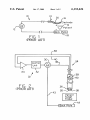
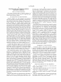
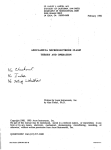
FIG. 1 is a schematic draWing of a basic knoWn RF
ablation catheter system.
60
863—876, October 1994. Moreover, such extreme heating of
the tissues can damage healthy tissue surrounding the tar
geted lesion.
Because of the dangers of overheating tissue With ablation
catheters, systems for controlling the temperature at the
ablation site are necessary. Such systems have been in use
65
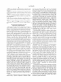
FIG. 2 is a schematic draWing of a knoWn temperature
controlled RF ablation catheter system.
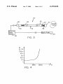
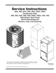
FIG. 3 is a schematic draWing of a temperature and
current limited ablation catheter according to the present
invention.
FIG. 4 is a graph illustrating a resistance and temperature
performance relationship of a positive temperature coef?
cient (PTC) device of the present invention.
6,132,426
4
3
device in series With an electrode to provide a current limited
and temperature limited device. FIG. 3 is a schematic
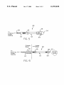
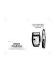
FIG. 5 is an alternative embodiment of a temperature and
current limited ablation catheter according to the present
invention.
draWing of a temperature and current limited ablation cath
eter 50 according to one preferred embodiment of the
present invention. Catheter 50 includes a ?exible body 52, a
FIG. 6 is an alternative embodiment of a temperature and
current limited ablation catheter according to the present
invention.
tip electrode 54 and a positive temperature coef?cient (PTC)
device 56, as Well as a conductor 58, and a connector 60.
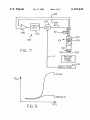
FIG. 7 is a further alternative embodiment of a tempera
ture and current limited ablation catheter according to the
Flexible body 52 extends from the proximal end 62 to the
distal end 64 of catheter 50. The composition of ?exible
body 52 is knoWn to those skilled in the art. Catheter body
52 should be suf?ciently pliable to permit the catheter to be
present invention.
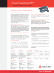
FIG. 8 is yet another alternative embodiment of an
ablation catheter of the present invention using tWo frequen
advanced through the vascular system of the patient, for
example, into the heart and ultimately into a pulmonary
cies.
FIG. 9 is a graph illustrating a resistance and temperature
relationship of a ceramic PTC device at multiple frequen
15
cies.
DETAILED DESCRIPTION OF THE
PREFERRED EMBODIMENT
consistent throughout its entire length. Additionally, catheter
The present invention includes a temperature and current
body 52 may be reinforced, for example, by use of a
reinforcing braid or other such suitable strand material
limited ablation catheter. As previously stated, ablation
catheters are Well recogniZed and important tools for con
veying an electrical stimulus to selected locations Within the
human body. FIG. 1 illustrates a schematic draWing of a
knoWn basic RF ablation catheter system 10. System 10
includes an RF signal generator 12, a catheter 14, a tip
electrode 16 and a backplate 18. An electrical conductor 20
Within catheter 14 extends betWeen and electrically connects
electrode 16 to RF generator 12. In operation, RF generator
vein. In one embodiment of the present invention, the distal
portion of catheter body 52 may be more pliable and less
stiff than the remaining proximal portions of the catheter to
assist the catheter in the advancement throughout the body.
HoWever, the pliability of catheter body 52 may also be
having high temporal strength.
25
Tip electrode 54 is connected to distal end 64 of catheter
50. Tip electrode 54 is used to deliver current from an
external poWer source 66 to the tissue to be ablated. Tip
electrode 54 is a standard tip electrode knoWn to those
skilled in the art. The single conductor 58 extends from
proximal end 62 to distal end 64 Within ?exible body 52.
Conductor 58 conducts the current from external poWer
source 66 to tip electrode 54. The current loop is completed
12 feeds a current to catheter 14 via conductor 20. During
the delivery of RF energy, alternating electrical current
traverses from tip electrode 16 through the intervening tissue
through the patient and back plate 69. Connector 60 is
19 of the patient to backplate 18. The passage of current
betWeen conductor 58 and external poWer source 66. In the
optionally provided at proximal end 62 to ease connection
through the tissue results in resistive (joule) heating. When
preferred embodiment of the present invention, external
using an ablation system, the targeted tissue must be heated
to temperatures above approximately 50° C. for effective
ablation. HoWever, temperatures at and above approxi
mately 100° C. at the electrode/tissue interface can result in
poWer source 66 is an RF generator, and reference Will be
35 made to an RF generator from hereout.
RF generators are knoWn in the art. Examples include the
EFT-1000TM from E.P. Technologies, the EP-ShuttleTM
manufactured by Stockert GmbH and the RFG-30TM from
boiling of plasma and adherence of denatured plasma pro
teins to the ablation electrode. The formation of the coagu
lum on the catheter tip causes a rapid rise in electrical
Radionics, Inc. These devices typically produce radio fre
impedance and a fall in the thermal conductivity resulting in
loss of effective myocardial heating. Because of the dangers
of overheating tissue With ablation catheters, systems for
controlling the temperature at the ablation site are necessary
and such systems have been in use for many years.
FIG. 2 illustrates a knoWn ablation system 22 for con
trolling the temperature at an ablation site. Ablation system
22 contains a catheter 24 having a tip electrode 26 and a
thermocouple 28 connected to the distal end of catheter 24.
System 22 also includes an RF generator 30, a control unit
32 and an ampli?er 34. Electrode 26 is connected to RF
45
generator 30 through a conductor 36. Thermocouple 28 is
connected to RF generator 30 through control unit 32 and
ampli?er 34 via a pair of conductors 38, 40. Abackplate 42
is also connected to RF generator 30 via conductor 43 to
maximum change in impedance (A) setting, selectable
55
provide a return path for the current. In system 22, the output
from ampli?er 34 is indicative of the temperature sensed by
thermocouple 28 and is used by control unit 32 to control the
duty cycle or poWer level of RF generator 30. Despite this
temperature control arrangement, this knoWn ablation sys
tem may fail to optimally regulate temperatures at the target
56 acts as an intrinsic fail-safe current limiting device. In the
embodiment illustrated in FIG. 3, PTC device 56 is posi
tioned adjacent tip electrode 54 but is not in thermal contact
With electrode 54. In the embodiment illustrated, PTC
device 56 is positioned approximately 5 cm from distal end
64. This is done for ease of construction. It should be noted,
tissue due to the possibility of: (1) reliability/manufacturing
The present invention provides a radio frequency ablation
catheter using a positive temperature coefficient (PTC)
betWeen 1—999 Q.
In the present invention, positive temperature coef?cient
(PTC) device 56 is connected in series betWeen proximal
end 62 of catheter body 52 and tip electrode 54. PTC device
problems; (2) inaccurate temperature signal transmission;
and (3) a lack of other limits on the RF energy provided to
the tissue.
quency signals in the 500—1000 kHZ range With poWer levels
in the 0—100 Watt range. These devices also have minimum
and maximum impedance cut off ranges. For example, the
EFT-1000TM has a pre-set 300 Q maximum impedance cut
off and a pre-set 50 Q minimum impedance cut off. The
maximum impedance cut off is to alert the operator, for
example, that the catheter is broken and therefore there is an
open circuit. The minimum impedance cut off is to alert the
operator, for example, that there is a short circuit some
Where. The EP-Shuttle TM by Stockert has operator selectable
maximum and minimum impedance cut off ranges. The
maximum impedance is selectable betWeen 50 and 300 Q
While the minimum impedance is selectable betWeen 20 and
200 Q. The EP-ShuttleTM also has an operator selectable
65
hoWever, that PTC device 56 could be positioned anyWhere
betWeen poWer source 66 and tip electrode 54 as Will be
described in greater detail beloW.
6,132,426
6
5
drops into an acceptable range. Cooling is provided by the
rapidly ?oWing blood in the vascular system. Maintaining
the temperature beloW 100° C. by using PTC device 56
prevents the boiling of plasma and the adherence of dena
As previously stated, PTC devices are known as positive
temperature coef?cient devices. A known technique for
making a PTC device is to use a very thermally expansive
polymer that is blended With conductive materials. In this
case, at loW operating temperatures, the device may have
very loW resistance, typically less than 1 ohm. When a high
current ?oWs through the device, the device Will begin to
heat from joule heating. The increased temperature Will
cause an expansion of the polymer and change it to an
amorphous state. This change separates the conductive paths
10
Within the polymer and causes a dramatic increase in the
device resistance. The device resistance can change by a
factor of 10,000,000 to 1 before the device fails. This
dramatic response is illustrated by the graph in FIG. 4, Which
illustrates a sample resistance and temperature performance
relationship of a positive temperature coef?cient device.
It should be understood that the resistance/temperature
relationship shoWn in FIG. 4 is only shoWn as an example
single conductor 58 as opposed to a common three Wire
con?guration that extends through prior art systems such as
15
of one con?guration of a PTC device. This relationship may
be altered and tailored to the user’s speci?cations depending
upon the siZe, shape, and type of PTC device used. For
example, the PTC device can be designed to have the rapid
based upon the type and amount of poWer used so that a
25
predetermined temperature range can be identi?ed at Which
PTC device 56 limits the current and limits the temperature
for ablation.
In addition to eliminating or reducing the extra number of
Wires that Would be necessary to support a thermocouple
based temperature limiting system, catheter 50 of the present
invention using PTC device 56 also provides a fusing-type
capability for catheter 50 by virtue of its current limiting.
Because of the current limiting capacity, a patient and/or
limited ablation systems.
One knoWn PTC device is made by the Raychem Corpo
ration of California under the brand name PolySWitch® Rxe.
This Raychem model is not reactive (having no internal
capacitance), permitting the polymer PTC device to function
Well at higher radio frequencies typically used for ablation.
HoWever, another knoWn PTC device is made by the
Siemens Matsushita Component Company, Which has a
ceramic construction Well suited for limiting currents at
moderate temperatures. Other PTC devices also may be used
Without departing from the spirit or scope of the present
invention.
In operation, RF current is delivered from RF generator
66 through conductor 58 of catheter 50 to tip electrode 54.
With tip electrode 54 in contact With the target tissue Within
that shoWn in FIG. 2 to support a thermocouple. Moreover,
since PTC device 56 need not be placed directly adjacent to
tip electrode 54, the distal end of the catheter can be of a
smaller design or of a design having different con?gurations
not limited by the presence of a thermocouple. As previously
stated, the particular tissue temperature at Which PTC device
56 increases its resistance exponentially can be selected
20
rise in resistance occur at approximately 130° C. as in FIG.
3, or to have it occur at greater or lesser temperatures. This
gives great ?exibility in designing current and temperature
tured coagulum to tip electrode 54 Which Would otherWise
inhibit effective ablation.
Catheter 50 of the present invention provides a simple,
elegant solution With numerous advantages. First, the use of
PTC device 56 alloWs temperature limiting or regulation of
ablation catheter 50 at tip electrode 54 by the use of only a
30
catheter 50 is protected in the event of an electronics fault in
the control unit or external poWer source Which might
otherWise cause the current to pass, or increase Without
constraint. Utilizing a single conductor Wire in conjunction
With a PTC device also eliminates the necessity for a
35
feedback loop for monitoring and gauging the accuracy of a
temperature signal from a thermocouple. Once the PTC
device is selected for the desired predetermined temperature
range at Which it Will limit the current, then a feedback loop
for monitoring the temperature of the tip electrode is no
40
longer necessary.
poWer is delivered to the target tissue With the system circuit
In one alternative embodiment of the present invention,
PTC device 56 is insulated from the ambient conditions
being completed through conductive backplate 69. RF
(e.g., surrounding vasculature and blood ?oW). In this
the heart (or other portion of the vascular system), the RF
embodiment, When PTC device 56 heats up from an over
tissue to heat to a temperature of betWeen 50° C. and 100° 45 current situation it does not cool doWn. This response results
poWer is supplied through tip electrode 54 to cause the target
in a permanent/effective shut doWn of ablating the target
tissue for tWo reasons. First, because of the high impedance
of PTC device 56, RF generator 66 Would shut doWn.
C. Heating the target tissue into the desired ablating range
requires the application of substantial current through PTC
device 56 to tip electrode 54. As the required current level
increases, PTC device 56 begins to change to an amorphous
state, thus increasing its resistance. It must be remembered
Second, even if RF generator 66 did not have a maximum
50
impedance cut off feature, the current passing through tip
the siZe, shape and type of PTC device selected. Using the
electrode 54 Would be limited as to no longer effectively
ablate the tissue. In this embodiment, PTC device 56 acts as
relationship illustrated in FIG. 3, at current levels required to
achieve ablation temperatures above 100° C., an ultra-high
target tissue While alerting the operator to investigate the
that the resistance/temperature relationship depends upon
a fail-safe feature thereby protecting catheter 50 and the
resistance is exhibited by PTC device 56. During the period
55
of time in Which PTC device 56 is changing from loW
resistance to high resistance, the current to electrode 54 is
being reduced to effectively limit the current to electrode 54.
Once the resistance of PTC device 56 is high enough, the
maximum impedance cut off, or the maximum change in
60
impedance cut off for the EP-ShuttleTM, Will be triggered
causing RF generator 66 to stop outputting the RF signal.
shoWn in FIG. 5 or by other means knoWn to those skilled
Thus, the current is limited. This also limits the temperature
at the target tissue. By properly selecting the PTC device
characteristics, the temperature at the target tissue may be
maintained beloW 100° C. RF generator 66, Will stay off
until PTC device 56 has cooled doWn such that its resistance
ablation shut doWn.
In another embodiment of the present invention, a cath
eter 80 includes substantially the same features and struc
tures as catheter 50 except that PTC device 56 is in mechani
cal and/or thermal contact With tip electrode 54. Thermal
contact can be established by direct physical contact as
65
in the art for providing thermal connectivity and conductiv
ity betWeen tWo devices such as PTC device 56 and tip
electrode 54. By establishing thermal contact betWeen PTC
device 56 and tip electrode 54, catheter 80 has enhanced
temperature limiting/shut off features in addition to the
current limiting features provided by PTC device 56.
6,132,426
7
8
Accordingly, in this embodiment, PTC device 56 is no
longer a pure current sensing limiter.
In operation, catheter 80 is placed Within the vascular
providing fail-safe current and temperature shutdoWn lim
iting characteristics by use of the PTC device 112. This
embodiment maximiZes the temperature regulating charac
teristics of the ablation catheter.
system and tip electrode 54 is arranged for ablating the target
tissue. By virtue of its positioning in physical contact With
tip electrode 54, PTC device 56 is in contact With rapidly
?oWing blood through the vascular system. The blood
?oWing by PTC device 56 Will act as heat sink removing
some of the heat generated by PTC device 56. This cooling
effect alloWs PTC device 56 to tolerate a slightly higher level
of current before exhibiting a very high resistance than
Would be possible if PTC device 56 Were not being cooled.
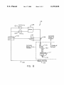
FIG. 8 illustrates a further alternative embodiment a
catheter ablation system 114 according to the present inven
tion in Which tWo frequencies are used for ablation. Ablation
system 114 includes a catheter 115, tip electrode 116, a
ceramic PTC device 117, a control unit 118 and a conductive
10
signal generator 124, a frequency mixer 126, as Well as a
Moreover, since the surrounding blood effectively cools
PTC device 56, PTC device 56 Will not stay in a very high
resistance state permanently after a current limit condition
backplate 119 connected via conductor 120. System 114
further includes a 500 kHZ RF signal generator 122, 1 kHZ
current sampling resistor 128 and frequency selective ampli
15
has been reached. Once catheter 80 is properly positioned
Within the vascular system, RF poWer is delivered to tip
electrode 54 from the external poWer source. With tip
electrode 54 in contact With the target tissue, the RF poWer
is delivered to the target tissue With the system circuit being
?er 130 tuned to 1 kHZ. Ceramic PTC device 117 and tip
electrode 116 are electrically connected via conductor 132
and are embodied in a catheter structure in accordance With
the other embodiments of the present invention shoWn in
FIGS. 3—7.
As shoWn in FIG. 8, system 114 uses tWo frequencies,
namely 500 kHZ and 1 kHZ mixed via mixer 126 and
completed through backplate 69. As the temperature of the
target tissue rises, so too does the temperature of PTC device
56 because it is in thermal contact With tip electrode 54. The
target tissue Will continue to be ablated until the temperature
delivered through current sampling resistor 128, ceramic
PTC device 117 and tip electrode 116. The voltage drop
across the sampling resistor 128 is ampli?ed by frequency
PTC device 56 to change into a higher resistance state.
Assuming that RF generator 66 is programmed to alloW a
moderate resistance change, the amount of current to tip
132 that is indicative of the current ?oW at the loW frequen
cies. In this system, if the temperature rises at ceramic PTC
at the electrode/tissue junction rises to a level Which causes 25 selective ampli?er 130 Which is tuned to 1 kHZ. This
ampli?cation produces a signal ?oWing through conductor
device 117, then its impedance at loW frequencies goes up
dramatically. This relationship results in a decreased current
?oWing to tip electrode 116 With the output from ampli?er
130 decreasing as a result of this sensed impedance change
causing the control unit to reduce the 500 kHZ output. This
electrode 54 Will be automatically regulated to keep the
temperature at the electrode/tip junction at an optimal level.
In another embodiment of the present invention, Which is
illustrated in FIG. 6, catheter 90 is provided Which has
substantially the same features and attributes as catheter 50
approach alloWs the precise monitoring of temperature along
of the present invention, except that catheter 90 includes
PTC device 56 at proximal end 62 of catheter so that the
With the use of an intrinsic current and temperature limiting
35
PTC device remains outside of the body of the patient during
an ablation procedure.
Catheter ablation system 114, as shoWn in FIG. 8, takes
Operating catheter 90 With this arrangement alloWs PTC
advantage of the unique properties of ceramic PTC devices
device 56 to operate as a pure current limiter With no
Which are very capacitive. The resistance of ceramic PTC
devices increases very little in response to temperature
changes When the ceramic PTC devices are run at high
frequencies. This behavior results from the capacitive cou
temperature sensing characteristics. In addition, since PTC
device 56 is not at the distal end of catheter 90, construction
of catheter 90 is greatly simpli?ed and permits distal end 64
of catheter 90 to be formed With a smaller diameter tip Which
is useful for insertion into small regions of the vascular
system. Of course, the PTC device is still electrically
45
connected to the single conductor 58, although being located
at proximal end 62 of catheter body 52.
FIG. 7 illustrates a further alternative embodiment of the
little increase in resistance occurs With the increase in
temperature.
55
Yet another use of the present invention is linear lesion
ablation catheters. Such catheters are very long Which results
in a high current density at the ends of the catheter thereby
generating hot spots of excessive temperature. By using a
PTC device of the present invention, current could be
limited at the hot spots at the ends of the long catheter by
converting the ends of the linear lesion catheters to small
to provide a return path for the current. A PTC device 112
ring tip electrodes in combination With the PTC approach. A
variant on this design Would include using multiple PTC
is electrically connected adjacent tip electrode 102 via
conductor 107. It should be noted that PTC device 112 can
thermocouple temperaturelimiting arrangement While still
Which is a graph illustrating a resistance and temperature
relationship of a ceramic PTC device operating at frequen
cies of 1 kHZ and 500 kHZ. As can be seen, in the loW
temperature increases While at higher frequency range, very
includes an RF generator 104, a control unit 105 and an
be located remotely from tip electrode 102, similar to the
embodiment of catheter 90 (see FIG. 6) or in direct thermal
contact With tip electrode 102, similar to the embodiment of
catheter 80 (see FIG. 5). In this embodiment, temperature
can be precisely monitored by combining the standard
pling across the grain boundaries in the ceramic composition
of the PTC devices. This relationship is shoWn in FIG. 9,
frequency range a dramatic increase in resistance occurs as
present invention. In this embodiment, an ablation system
100 is provided. Ablation system 100 contains a catheter 101
having a tip electrode 102 and a thermocouple 103 con
nected to the distal end of catheter 101. System 100 also
ampli?er 106. Electrode 102 is connected to RF generator
104 through a single conductor 107. Thermocouple 103 is
connected to RF generator 104 through control unit 105 and
ampli?er 106 via a pair of conductors 108, 109. Abackplate
110 is also connected to RF generator 104 via conductor 111
mechanism, all accomplished With the single Wire conductor
132 Which simpli?es the catheter construction.
devices on each end of the long catheter.
An ablation catheter of the present invention incorporat
ing a positive temperature coef?cient conductor provides
65
numerous advantages in radio frequency ablation. The FTC
device provides a built in fail-safe current limiter to avoid
over-ablating the target tissue thereby protecting the patient,
6,132,426
9
10
While insuring effective ablation With the catheter by pre
venting coagulation adherence to the catheter electrode tip
and damage to the catheter and patient from overheating.
a control unit;
a frequency mixer;
a loW frequency generator and a high frequency generator
connected in parallel to and extending betWeen the
control unit and the frequency mixer;
a resistive component electrically connected betWeen the
Use of the PTC device to limit current and/or temperature at
an ablation site Within a vascular system greatly simpli?es
the task of temperature regulation Which Was previously
provided by thermocouple-type systems.
Although the present invention has been described With
reference to preferred embodiments, Workers skilled in the
art Will recogniZe that changes may be made in form and
detail Without departing from the spirit and scope of the
invention.
What is claimed is:
1. A radio frequency ablation system comprising:
an elongate ?exible catheter including an electrical con
ductor having a proximal end and a distal end;
an electrode electrically connected to the distal end of the
conductor;
a ceramic-type positive temperature coefficient (PTC)
device electrically connected betWeen the proximal end
of the conductor and the electrode,
frequency mixer and the ceramic-type PTC device;
a frequency selective ampli?er having an output con
10
nected to the resistive component and an inlet con
nected to the control unit; and
a conductive plate electrically connected to the control
unit for contacting a patient.
2. The ablation system as in claim 1, Wherein the PTC
device is adjacent the electrode.
3. The ablation system as in claim 1, Wherein the con
ductor comprises a single conductor Wire.
4. The ablation system as in claim 1, Wherein the PTC
device is a ceramic-type PTC device.
*
*
*
*
*