1
48784
OCTOBER
1988
THE MAGAZINE FOR THE ELECTRONICS ACTIVIST!
A modern version of that fascinating device!
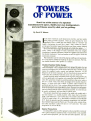
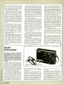
Towers of Power
Tower speakers that deliver top-notch sound
and you can build them yourself!
-
Mice, And More
Pointing devices make life with your PC more fun!
I
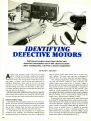
Identifying Defective Motors
Is the problem in the motor, or elsewhere?
After reading this article, you'll know!
Computer Speech Synthesizer
Give your computer the gift of gab!
10
i
48784
8
._._ _=_
- ___ _
_ __ __
C O
P O
R
T/
R A
_
INTEGRATED CIRCUITS
War,
1400
l.602 TTl
TT L
29
61602
,.. ,an
=;;:
P.M
614.
M
ivR
77
6419160
SO
w
66.6
4.66
il
7456
4517666
16.6
4.767
uÌw
"
12
;Zit
7664
746,
616
.0474
S.?
466
w<:Rn
.67204
6
wcli
4.141
fRR
17°.
746161.
1i
667.
1F
¡w'
«rr.
i.
77
2
666.
64606
6 SP
6
0616
0616
2
10
2
1646
200
.44001S
61401646 6 150
61166
1.2
ree
..
s11.,A
44612
A
SO
601
MCA
TO
6
3á
1131
ri
PANASONIC V SERIES
TO 10
0110
011
4 77
716
66165.16
Rt1
6416.172
1'.
1
6.51406
1041
2.62220
.
ii+pi4
40 IS
iR
'QM
mo
14666,0
.796
6446
METAS OXIDE FILM ASSISTONS
3%
1rM
01 67
ii
564
64.64
5.667
1.6
6,66
219
;60 S2
1644.2
ñ
1.66.0
18
6/1461.0,
6644
.422224
66121
...
TO
41:.0
n
4
itw
4:,910
D
rR
:0é
I
4436.
iE
m
.
7.7
6.461.
664,22
66
4461
5.6.100 6.6 60046 ,160.
Swam/.R
W1s
46260
6.66
fi
/04466
64.274
rn
.Lr...
1
ó
4Y:yi"eN
66/01
40á
.66111
24.1.1116
eon
44704
M..
667,
036
016
r.+
no
6656
406
22
WAS
..r ..........,..t..
0406
.61
6066
6-106
40 07
6
66411
.6117.
`..m,
sao
SO
nñ
mass
m
611.6
ecesee
lt
10,
rOÑ
mum
hnorn
.66
KV,
9
.07
111
lFm
642141
4"'"
Ka
60
i1
N 54
In
TN
L
r
:0'10.v
6014,
666
65.164
,.1.,
I
NR.f
.47640
PO
35.
.10
666642
CMOS
6
6536)
+Snow
7466764
16
moo
1.46
6.111
MON
SG
mé
6.61110
66
46
25
646
Á.
s
602
SS
7
6.061 1.77
6.40
ww.+11
"66,
/
74276
16
MS.
616
62170
5.46.7611
17
146
62014
61. 6110
4.5116
?
261013
.220.11,6
61.16
666/4
As
10
1v, WIREWOUNO RSC. RESISTORS
066
1.
06610144
0AP
7667.
C?
2666
21476
60166
7412404
6
66411
SO
iN
n
110
TO 237.
.66.
6.660
6
12
41041L20
116
611064
A
1
.66
10/
611114
CO
4
2.1114
0667
.0022.
/
.62110
2621044
S
0666
.1,174
91015N9t2DIGI KEY CORP
.10
10
ro
TWA
MS IAL ORIOL FILM RESISTORS
TO IS
K. 664
2661
04426
.*
64.1116
211SE1IMO
666/104
KW..
SS
46,2.6
FAX
6282n14
2646
c01114
6
64016
T.1.,
1174
24.60
COPr
Aose
4.676
662.
66516
.96
IV]1]
0.6221
&I.E.
vou
666
62
r
262216
..N
M
.246
ro
6226
N
6266
766
466
N1
215
lv.
2.6
262.216
6674
rI
MOM
Pusno Elmo
Mir
.
61416
4.616
66,66
0441.6
6.116
w
1- 800 -344 -4539
/AK
26727
2
67
SOW
40,1
suntss
7
N
O
E4w.06
56,0404 11.
0.66
20 00
6
PS
6.4
606
.1ID
iFÌ 1.6;
646
6466
.
..
,...,..AN..r
V111
A:Ro
IIÌ 1®
26
15 211
20 DO
ono
ono
ót:
WIN
4.
41114
6
666
sA
tP.
3i2;
MM1
K1
VARA
QUARTI CRYSTALS
PANASONIC LS SERIES
af
Do
61
!1K
.16
64206
44
116 .61
2202
6111.
ISO
0
626
65
220
OW
60
10 10
10 DO
10 220
62716
61
16
10
60
7 00
2 JO
MOM
22 SO
21 66
SWF
Tp
TO
;IS
Rue
10
r0
MEP
* errs
TO 220
TO SW
260
Z'
621,
seal
;TSFTO
66,
40
0
no
Nos
.6111
1612
rave
.37
16
00101
:5
4
642
606.1
61414
11.111
061424
}p
1EMC40
CMOf
AA x
S'1.
..ún1.
CARSON FILM RESISTORS
222.999.2.22 221121226
66
...
1166
.D
PS
rwc.+
74.6.4
33
INC7,1t
S1116.
20
PAS
PANASONIC
OPTOELICTRONICS
á rj
2
oat
0
73
IA
640
21
42
so
w"'cIljr.
Is
4 ISO
220
/606
LAW.
S
IS
27
62
6
1Vr
1.14
RI
1166
01
NDIO..w..ErMARa,+mNw AMn sonny n+.r DON ,Iola roI1MECan......mF ono mph, lrvADF.uvrl.arlr.assn. f
W. pr M.yP.yPra.I.r+.c.10 Waw.
C.rl.a..M M..co wlr.n owe or mom, man .N 1r.I.NM.
Om,
M..... C.r.a...ra M... D
.
, ..
..-.
..USA
NS IN 4171 IA4 EM
III NI N/41. IT NM NN NN ERNE
..,.1
11n:rNrMt......
S AW.
vdrpOy Rrvlorrw Nywant wlrr.IM.Lott+.nll U
M. SI/. Tipi bon
NISI.
r...............r.. Y.,.oCrvyVáAaCOD0IMF/EISIMRAR/E.:An.wrrlLot..Mn04644nlrr44tl6R44
ln.rp..4Pl..14.444. I4444I4 r.4.4 .nLo.ri...i
, ., ,. ,.. .. .,.
.. an t. new .rl.... VNNSS SLNUSCI RO CEYNOE NEINOUT ROIFCE -
WINS OMIEMNG ST PNOR. CRIA I
.
IN
12
T0 OIM MT.
P.O.
EERF.
NM
..
CIRCLE
11
ON FREE INFORMATION CARD
t
36
7
4
4.
16
SERVICE CHARGES
SALE SAS
NAILUSAII
a.N.Na
NMNM
MUM
UP
VOLUME DISCOUNT
t
ASP
101.71
A. M.M
AY Mi
NE CAO.
0004 N.N
1124.1104241.
S MP 11114,181
S
MET
N
LEU 1S'.
L... 16v.
SP
500.SFMN.SI
&IOWA
Up-
-
196 209.
LE6 2S%
INCLUDING
12 -PAGE
Volume 5, No. 10
U'Tun
OCTOBER 1988
CONSTRUCTION
30
35
41
42
82
Computer Speech Synthesizer-give your computer the gift of gab
Solid -State Tesla Coil -build this solid -state version of Tesla's most famous experiment
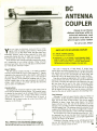
BC Antenna Coupler -lock in those distant stations with an external
antenna
Towers of Power -get the speakers you want without havng to second
guess the manufacturer
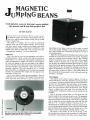
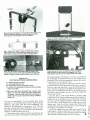
Magnetic Jumping Beans -your friends and family will get a kick out of
watching these little fellows do their tricks
FEATURES
17
59
66
73
The Gravity of Things -gravity may not be the constant that everyone
thinks it is.
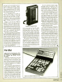
Of Mice, and More -look at what's available in pointing devices
Identifying Defective Motors -pull those old tape decks and turntables
out of the closet and put them back on track
E -Z Math -Network Analysis: learn the right way to analyze electronic
circuits
Solid -State Tesla Coil-page 35
HANDS -ON REPORTS
26
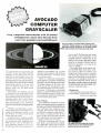
Avocado Computer Grayscaler -get crisp, composite monochrome, with
63
Digital Voice Recorder-an adaptable modular kit puts computer -age
16 brightness levels, from your CGA card
gadgetry on your workbench
SPECIAL COLUMNS
84
86
88
92
94
96
Ellis on Antique Radio
-a
-a
little housekeeping prevents a whole lot of
troubleshooting
Friedman on Computers
dual -purpose device backs up floppies and
provides IBM Macintosh compatibility
Saxon on Scanners -get nine -band coverage and 16- channel
programmability from a handheld scanner
Jensen on DXing -pioneer shortwave program celebrates its 60th birthday
Carr on Ham Radio-ham radio joins forces with computers to improve the
communications hobby
Circuit Circus-electronic pest controllers take some of the drudgery out
of maintaining your home
DEPARTMENTS
2
Editorial- change
4
Letter Box -the place to let yourself be heard
Electronics Library -spotlighting a knowledge storehouse
New Products Showcase -trends in the electronics marketplace
fingertip reference for the electronics hobbyist
FactCards
GIZMO Special Section -what's new in electronic doo-dads
Free Information Card -when in doubt, sound the manufacturer out
12
18
37
47
71
Towers of Power -page 42
Of Mice, and More -page 59
is inevitable
-a
Locating Defective Motors -page 66
1
Volume 5, No. 10
October 1988
The Magazine for the Electronics Activist!
Larry Steckler, EHF, CET
Editor -In -Chief & Publisher
Change is Inevitable
Letters from our readers tell us to never change our editorial
format. What they see in our magazine and what it does for them
is, more often than not, exactly what they want. Of course, we
love to hear things like that; compliments are always welcome.
But we like to hear your criticisms, too. It's your input that makes it
possible for the editors here to do their jobs properly.
When transistors first hit the hobby marketplace, many editors
hopped on the bandwagon. They were right. When integrated
circuits appeared, some editors were fast to promote their applications in hobby areas, others were slow.
The arrival of computers threw the electronics- magazine field
into turmoil. Computers are hardly a new topic (even wrote an
article on a basic computer project back in 1961), but in recent
years that subject area overwhelmed the editorial balance of
many hobby- oriented electronics magazines. Too many of those
magazines dedicated 100% of their content to computer-related
topics, and many new all- computer magazines were born.
I
could understand the introduction of new magazines that were
devoted exclusively to computers. What could not understand
was how or why already established hobby-electronics magazines would tie their future success to one area of electronics. To
me, it was a calamity to see loyal readers who were interested in
other areas of electronics so callously ignored and dropped by
magazine publishers.
I
I
Of course, if a magazine is to grow with its readers, change is
inevitable. Because of that, you can expect some change, be it
ever so slight, in almost every issue of Hands -on Electronics.
But our readers will never be discarded for a keyboard and
floppy -drive combo, or anything else for that matter.
Now, you may ask, what's the change for this issue? It's a slight
one, to be sure, and one that might not be noticed by many of our
readers. See if you can find it!
Next issue, will make another change, and I'll put that one right
on the front cover! Remember, change is inevitable.
I
Art Kleiman, editorial director
Julian S. Martin, KA2GUN, editor
Carl Laron, WB2SLR, managing editor
Robert A. Young, associate editor
Herb Friedman, W2ZLF, associate editor
John J. Yacono, associate editor
Brian C. Fenton, associate editor
Byron G. Wels, K2AVB, associate editor
Teri Scaduto, assistant editor
Kathryn Campbell, editorial assistant
Ruby M. Yee, production director
Karen S. Tucker, production manager
Robert A. W. Lowndes, editorial
associate
Marcella Amoroso, production assistant
Andre Duzant, technical illustrator
Injae Lee, assistant illustrator
Jacqueline P. Cheeseboro, circulation director
Nancy Estrada, manager, HOE Bookstore
BUSINESS AND EDITORIAL OFFICES
Gernsback Publications, Inc.
500-B Bi- County Boulevard
Farmingdale, NY 11735.
516293 -3000
President: Larry Steckler
Vice -president: Cathy Steckler
Cover photography by
Diversified
Photo
Services
Composition by
Mates Graphics
Advertising Sales Offices listed on page
11R
105.
®
I
Hands -on Electronks, (ISSN 0743-2968) Published monthly by
Gernsba,.k Pub,calions. Inc 500.8 BI- County Boulevard. Farm ngdale. NY 11735 Second -Class postage paid at Farmingdale. NY
and at additional mailing offices. One-year twelve issues. subscription rate U S and possessions 521 95. Canada $26.95. all other
countries S29 45 Subscnptwn orders payable m U S funds only
International Postal Money Order or check drawn on a U S bank
U S smote copy price $2 50 c 1988 by Gemsback Publications.
Inc All rights reserved Trademark registered in U. 5 and Canada.
Printed in U.S.A
.
Postmaster Please send address changes to Hands -On ElecPO Box 336. Mount Moms. IL
tronics, Subscnpbon Dept
.
61054-9932
e2/t4
Julian S. Martin, KA2GUN
Editor
2
A stamped self. addressed envelope must accompany all submdted
manuscripts and or artwork or photographs if their return is desired
should they be rejected We disclaim any responsibility for the loss
or damage of manuscnpts and Of artwork or photographs while m
our possession or otherwise
As a service to readers. Hands -on Electronics publishes available
plans or information relating to newsworthy products. techniques
and scientific and lechnologrcal developments Because of possihle variances m the quality and condition of materials and work manship used by readers. Hands-on Electronics disclaims any
responsibility for the sale and proper functioning of reader -built
projects based upon or from plans or information published in this
magazine
-
SELECT 5 BOOKS
;Tv
REPAIR
for only $3.95
Ftlll-and-I:a
ccl.cnd
Project.,
11
Iilcrtrunir,
S
:I
(values to $131.70)
270SP
1897P
and get a Free Gift!
513.95
HOME
ELECTRONICS
FIX -IT BOOK
Hew se Road
Electronic Circuit
Diagrama
2880
2861
READING
SCHEMATICS
ELECT
IEORY
1599P
-
2707 526.95
Counts as 2
inSP 51895
58.95
2883
025.95
$14.95
#
1536P
520.95
Electronics projects ... ideas ... the latest technology
all at up to 50% off publishers' prices
517 95
1'lt
521 95
ee
ELECTRONIC
CONVERSIONS
Formias
"ìymbo,s an,/
Rufus P Turner and Stan OíMNlaco
Membership Benefits
o
Irw w AM
Allroen 1r.s+rR
tatre.r
1667P
514.95
2925
515 95
ELECTRONICS
AND
THEANRN
EXPERIMENTS
vat-it
C(MO'l71TICAIDFD
Ns rRIX-t1ON
All books are hardcover unless numbers are followed by a "P" for paperback (Publishers' Prices Shown)
1988 ELECTRONICS BOOK CLUB', Blue Ridge Summit. PA 17294 -0810
POR DEF.
COMMODORE
a41IS
2882
524.95
Big Savings. In addition to this introductory
offer, you keep saving substantially with members' prices of up to 50% off the
publishers' prices.
Bonus Books. Starting immediately, you will be eligible for
our Bonus Book Plan, with savings of up to 80% off publishers' prices.
Club
News Bulletins. 14 times per year you will receive the Book Club News, describing all the current selections- mains, alternates. extras -plus bonus offers and
special sales, with hundreds of titles to choose from.
Automatic Order. If you
want the Main Selection, do nothing and it will be sent to you automatically. If
you prefer another selection, or no book at all, simply indicate your choice on the
reply form provided. As a member, you agree to purchase at least 3 books within
the next 12 months and may resign at any time thereafter.
Ironclad No -Risk
Guarantee. If not satisfied with your books, return them within 10 days without
obligation!
Exceptional Quality. All books are quality publishers' editions
especially selected by our Editorial Board.
2865
FREE when you join!
2809
528.95
Counts as
2
101
SOLDERLESS
BREADBOARDING
PROJECTS
tte-
Here's 15 Best Electronic
Projects From Delton T. Horn
Projects you can build -some
unique, some old favorites -from
the author's vast treasury of electronics know -how.
I><itIi
:ll-1 Ïtil Ì'alY/ritl'
l'Lrtmnic Pmirrth
37.95
(a
$21.95
r.11i4'11>
MAI aNLY
r1¡[T1L3
72814
SI I 95
value!)
MASTER
IC
COOKBOOK'
1493P
515.95
RUiuH
2985
$24
ilU1
1,1
'i99P
Blue Ridge Summit, PA 17294 -0810
518.95
Please accept my membership in the Electronics Book Club' and send the 5 volumes listec
below. plus my FREE copy of Delton T Horn's All -Time Favorite Electronic Projects (3105P)
billing me 53 95 plus shipping and handling charges If not satisfied. may return the books
within ten days without obligation and have my membership canceled. agree to purchase
At least 3 books at regular Club prices (plus shipping and handling) during the next 12 months
.nd may resign any time thereafter
111
,
NilYl\N,i11
re
ELECTRONCSBaohCiuE
9'
9i
DR
il Ili
811818
ELECTRONICS
PROJECTS
I
I
2800
523.95
2790
518 95
1367P
.dame
trET
Address
STUDY
GUIDE
City
State /Zip
917 9',
Phone
p--
Signature
2735P
513.95
2839P
57 95
valid for new members only Foreign applicants will receive special ordering instructions
Canada must remit in U S currency. This order subject to acceptance by the Electronics
Book Club'
RESP -1088
2941
S21 95
1421P
516 50
3
L
JL J
D
D
m
Hands -on Electronics, 500B Bi-County Boulevard, Farmingdale, New York 11735
No Dogs Allowed
Do you have a circuit for an ultrasonic- emission dog repeller? I'm interested in the frequencies and components
used. In particular, I need a suitable
"speaker," with enough power at those
frequencies.
-W.P., Wichita, KS
What a timely question! See this
month's "Circuit Circus" for some circuits that might be just what you are
looking for.
Tuned Out
I live in the hills of Southern California, where the terrain is good for deterring smog, but terrible for FM -radio
signals.
I bought a signal enhancer, but I
wasn't pleased with its performance. The
main problem was that it couldn't be
tuned. It would enhance a strong signal
if I was slightly off frequency, but it
wouldn't necessarily enhance the frequency I wanted. It only enhanced the
strongest signal.
My electronics teacher (who's the one
who suggested I subscribe to Handson Electronics) told me that there isn't
a signal to amplify. I hope he meant it
isn't worth the trouble.
Do you have a schematic and a parts
list for a tunable high -gain RF- amplifier system for my car radio?
-R.W.N., Canyon Country, CA
If
He could be right.
the signal
strength is too low in your area, no
amount of enhancement will help
with no signal there's nothing to enhance.
However, before we dismiss the question, there are a few points that should
be considered. The characteristic that
gives FM reception its interference free performance is called "capture effect." In essence, if there are two competing signals in a receiver's passband,
the receiver will lock onto, or capture,
4
-
the strongest one. That's why your enhancer isn't doing the job you thought
it would: It is enhancing both the strong
and weak signal equally, and your receiver is still locking onto the strongest
one.
If the distant station you are interested in shares its frequency allocation
with the local one, you're out of luck.
But if your receiver is poorly designed
and has an abnormally wide passband,
an outboard tunable filter may help.
But, while such filters are available for
other bands (shortwave, ham, AM broadcast, etc. ), we don't have a circuit that's
suitable for use in the FM- broadcast
band in our library.
Perhaps one of our readers can help
with this. you have a circuit that will
do the job, send it along; we'll publish
it in a future issue.
If
Old Issues For New Reader
The July 988 issue of Hands -on Electronics was the first one I've read. In
the "Letter Box," one of the answers
referred to a previous issue concerning
shortwave radios. I'm new to the radiofrequency field, and I'd like to learn
more about it. How can I order that
issue?
it seems that some people out there
are having problems assembling the projects in your magazine. it could be a
communications problem between the
authors and the editors. I would like
to suggest that you keep the explanations simple, and don't use any abbre1
viations.
A project I'd like to see is an emergency- ignition system, for cars with electronic ignitions commonly known as
a "hot box." I'm looking forward to
future articles.
-TS., Brooklyn, NY
-
Back issues of Hands-on Electronics, and more, are available from the
Reprint Bookstore. See the ordering coupon on page 102 for more information.
Buzzing About CPM
am writing about "fear of computers." Some of us are not afraid of comI
puters. We're madder than a bumblebee at how low you and other magazines have made us feel about our old
CPM computers.
Long, long ago, you were all pushing those CPM computers. Now that
DOS has come along, you've forgotten
the old CPM users. Why should you,
when we paid just as much for our CPM
computers?
-S. P.
,
Hayward, CA
I no longer drive my 1964 Rambler.
must admit that I miss it, but the wheels
I have today are more to my liking. I
1
like air conditioning. I like power windows. I like the goodies of today.
By the same token, I miss my old H89
Heathkit computer, but the current generation of MS -DOS machines, and the
new PSI2 machines, are clearly superior; it seems that the majority of computer users agree. We haven't forgotten, it's just time to move on.
Crossed Channels
The output channel on my cable -TV
converter is Channel 3, but my television set automatically goes to Channel
2 every time it's turned on. When I turn
on the box by remote, the TV goes to
the wrong channel, and I have to get
up to adjust it.
I need an RF modulator to put in circuit with the cable box, or one that goes
in line with the box and the TV. I've
seen them for Channels 3 and 4, but
never for Channel 2. Do you know where
I could buy one, or how I could build
one'?
-M.S.,
Apple Valley, MN
Most TV sets, including the newer.
electronically tuned ones, have a fine tuning control. Adjust that so that Channel 3 is received at the Channel 2 position.
Public Servants,
cies" -yet that state doesn't explain why
hams would have any more reason to
Not Public Enemies
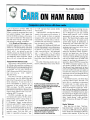
In "Saxon on Scanners'. Hands -on monitor police transmissions than anyElectronics, August 1988) it says that, one else. As a ham, I'll offer some enno- lightenment to anyone who may be wonaccording to one state's laws,
body except licensed hams can have a dering about that.
While most law- enforcement agenmobile receiver that is capable of receiv
cies now use the UHF bands for their
ing frequencies used by police agen
(
"...
routine communications, some local and
regional public-service agencies continue
to plug along in the VHF spectrum (the
150-MHz through the 170 -MHz bands.)
One of the most heavily populated ham
hands, the 2 -meter band, resides just
below those VHF public -service frequencies, at 144 MHz to 148 MHz.
Recognizing the broader appeal of
expanded- frequency coverage, many
amateur -radio manufacturers are now
selling 2 -meter mobile transceivers that
receive from approximately 138 MHz
to 175 MHz. Transmission, of course,
is restricted to the 2 -meter band as required by FCC regulations.
"/ could have sworn
this turkey stufe u
radio 00 his way out!"
NHOLD
With the no police scanners in vehicles" laws, the installation of an expanded- frequency 2 -meter transceiver
in a vehicle became, potentially, a de
facto crime. However, the mish -mash
of conflicting laws and ordinances are
mostly unenforceable -to the benefit of
hams and the community in general,
in my area at least.
The Amateur Radio Emergency Service (ARES) group in Santa Barbara
works in close harmony with numerous
local, regional, state, and national emergency- and disaster -service agencies.
Scanning those services' VHF frequencies in our vehicles alerts ARES members to events for which our special emergency- communication services may be
requested. In many instances, monitoring those frequencies has helped us gain
valuable lead time as we gear up in anticipation of the official "Emergency
Callout" that is usually initiated by the
Santa Barbara County Sheriff's Office.
We hams have those transceivers, we
use them, and it is highly unlikely that
we will stop using them due to indistinct and ill- directed politics.
enjoy "Saxon on Scanners," as
do the entire magazine. Hands-on Electronics gets a gtxxl reading every month,
then passes on to others who enjoy it
at least as much as I do.
-W.G.H., Santa Barbara. CA
1
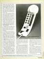
IT!
IT ANYWHERE YOU WANT
tilt and rout,
)\\
work holding , tens alb
.
electronic
PanaVise
them
\
uu to position,
.
your projects without removing
\V ith over
from their holding devices!
in -USA
madeand
30 years experience
reliable, long ensures
PanaVise
quality,
lasting service.
most
STANDARD PANAVISE:Our
PanaVise
popular vise, the Standard useful
is an extremely versatile,
full
s
workbench tool. l
open ab
2.25;' and the p
through
base tilts, turns and rotates control
convenient
One
planes.
three
position!
knob locks work into any mini -vise
purpose
allThis durable,
will destands about 6" tall and
Model
to
CENTER:
MULTI -PURPOSE WORK Opening
Self -Centering Extra Wide"split ball"
Head (opens to 9"), famous
three planes),
Standard Base (moves in Mount (with
of rugged service.
and convenient Tray Base
to hold liver years
difficult
handle
$33.95.
wells'
parts
#301.
#350. $52.95.
items with ease! Model
CIRCLE
7
CENTER: A
ELECTRONIC WORKto make work
combination
complete
manageable!
areas more efficient and gently, but
Circuit Board Holder to 12" wide.
firmly, holds PCB's up
(moves in
Add oúr Standard BaseMount (with
Base
Tray
planes),
three
(selfparts wells), and Solder Station
perfect
centers wire and
del
angle) foora great combo!
$54.95.
#324.
supplier
See your local electronics
you
for the source nearest
king lR.Ph A
911g1Nt (213)
or contact Pian\
Ise
29th
595-'621
ON FREE INFORMATION CARD
5
413 JDR Microdevices
Complete customer satisfaction... superior service... friendly, knowledgeable personnel
quality merchandise... providing the best values in leading edge technology.
STATIC RAMS
256.4
1024.4
1024.4
2048.8
2048.8
HM6116 4
2048.8
HM6116 3
2048.8
HM6116LP 4
2048.8
HM6116LP 3
2048.8
HM6116LP 2
8192.8
HM62641P 15
HM6264LP-12
8192.8
HM432561P 15 32768.8
HM432561P 12 32768.8
HM43256LP-10 32768.8
450ns1
2112
2114
299
1450ns1
1200ns K LO W PO W E
21 141 2
TMM2016 100
SPOnIGHT
99
F
149
1
110Ons1
95
3 29
3 95
1
1200ns11CMO51
1150n11CMO51
1200nsIICMO511LPI
429
495
549
1150ns1ICMOS111P1
1120ns11CMOSKLPI
1150nsIICMOSIIlP1
649
1120nsIICMOS11lP1
699
1150ns11CMOS11LP1
12 95
14 95
19 95
1120nsIICMO511LP1
1100ns11CMOS11LP1
1
MB EPROMS
CMOS DESIGN
FOR LOW POWER
$34.95
DYNAMIC RAMS
4116 250
16384.1
16384.1
411150
16384.1
4116 120
16384.1
MK4332
32768.1
4164150
65536.1
4164 120
65536.1
MCM6665
65536.1
TMS4164
65536.1
4164 REFRESH 65536.1
TMS4416
16384.4
41128 150
131072.1
4116 200
1120nsI
3 19
12000s1
1150ns1
95
I 95
RE REE-HI 2 95
3 75
1
1048576.1
r
1
12 45
12 95
13 45
95
49
95
1
1
BASII
8203
8205
8212
8216
8224
8228
8237
8237
8243
8250
34 95
I 49
95
6 49
5 99
7 95
2 49
3 95
9 95
7 95
9 95
14 95
1
8741
695
3495
3795
8200
3
8039
8052AH
8080
8085
8086
8088
8088 2
8155
8155 2
595
795
110005.1
8000
8031
8035
1
1150ns1
11500s1
11500s1
11200s1
1100ns1
I1000s11CMOS1
1120ns1
65536.4
262144.1
4125120
262144.1
41256-100
262144.1
HM51258 100 262144.1
MB 120
1048576.1
MB-100
49
89
99
1
49
6 95
2 89
1150n0IPIN
I150ns1
TM5446415
41256 150
1
1250ns1
1200ns1
1150ns1
1120ns1
1200ns1
1150ns1
200 NS
ORGANIZATION
1281( x 8
8748
8749
`755
14 95
3
8255
8259
29
149
1
2
2
3
5
8257
8272
8274
8275
8279
8279
8282
8283
8284
8286
8287
8288
25
95
4 75
1
95
6 95
8251
1
8251A
8253
8253.5
8255
1
1
1
1
5
1
29
69
59
95
49
59
195
229
8259-5
49
25
2 25
4 39
4 95
1695
2
2
5
3
3
2
3
3
4
49
95
95
95
25
95
95
95
EPROMS
1024.8
2048.8
2048.8
4096.8
4096.8
4096.8
4096.8
8192.8
8192.8
8192.8
8192.8
8192.8
2708
2716
2716 1
TM52532
2732
2732A
2732A 3
27C64
2764
2764-250
2764 200
MCM68766
27128
27C256
27256
27512
27C512
4 95
1450ns1125V
1450ns1125V
(350ns1125V
(450n51125V
1450ns)125V
49
95
5.95
3 95
3 95
(250ns)121V
8087
8087-2
8087 1
80287
80287 -8
80287 -10
80387-16
80387 20
4 25
1200ns1121V
1250n0 (12 5V CMOS 4 95
45000112 SVI
349
3.69
(25000112 SVI
4 25
12000.512 SVI
(35Ons)121V1124 PIN 15 95
4.25
125000(12 SV)
163848
32768.8
12500.)112 SV CMOS.
5
8
10
6
8
10
16
20
MHz
MHz
MHz
MHz
MHz
MHz
MHz
MHz
95
95
65536.8
11 95
65536.8
125000112 5V CMOS. 12 95
Program Volte.
32768.8
7
(250n.)(12 SVI
125000/12 5V)
1.0 MHz
6502
2.25
65CO2
6520
6522
6526
6532
6545
95
1 65
2 95
ICMOSI
1395
95
2 95
2 95
5
6551
2.0 MHz
6502A
6520A
6522A
6532A
6545A
6551A
2 69
2 95
5 95
11 95
3
3.0 MHz
65028
Z-80
95
695
2.5 MHz
4
25
CONTROLLERS
1
25
4.0 MHz
280A CPU
29
69
95
5 95
1 89
5 95
5 95
5 95
1
ZBOA CTC
180A DART
1
5
280A DMA
ZBOA PIO
¿BOA SIO O
180A 510 1
280A 510 2
6.0 MHz
7808
7808
1808
7808
7808
2808
CPU
CTC
PIO
GART
510 0
510 2
28671
6 95
12 95
12 95
9
954
CLOCK
1.0 MHz
95
2 95
3 95
1
295
6821
6840
6843
6844
6845
6847
6850
6883
2
95
1
95
2
95
1
25
95
95
95
75
75
3
4
6
2
4
95
22 95
1
MM58167
2
3
681309E
549
68809
5
68821
68845
68850
68000
6
1
95
95
99
85
4.95
175
9.95
61118876
1691
2143
9216
V70'
V20'
V20'
5MHz
8MHz
10
MC 14411
95
4702
4
9
COM8116
8 95
95
INTERSIL
9 95
1095
99
3 85
S 95
1
15.95
ADC0804
ADC0809
DAC0800
DAC0808
DAC1022
MC 1408 L8
NH,
3
4
3
4
3
9
6
10
95
95
95
95
95
95
95
95
CRYSTALS
32 768 KHz
10 MHz
1
8432
20
4576
3.579545
2
3.29
1 95
595
95
8T28
1
29
8T97
59
DP8304
2 29
9334
1
75
9368
2 85
9602
69
ULN2003
79
7 95
MAX232
1 95
MC3470
MC3487
2 95
`AY53600 PRO 11.95
95
295
2
95
195
1
1
95
95
40
50
195
195
5
1
0688
6144
80
100
10 738635
120
14 31818
160
18 0
18 432
20 0
32 0
2 99
3 85
895
1095
1295
V30
8MHz 1395
'Replaces 8088 to
speed op PC 10 40"
60
DARTS
MISC.
GENERATORS
JDR Microdevices and the JDR
95
95
95
95
29 95
4 39
4 39
12 95
12 95
6 95
6 95
6 29
20 SERIES
22 1184
24 0
BIT RATE
ICL7106
ICL7107
IC17660
IC18038
ICM7207A
1CM7208
12
12
19
19
C16450
MM58174
MSM5832
2.0 MHz
68800
68802
1793
1795
1797
2791
2793
2797
8272
UPD765
IM6402
IM6403
1N58250
CIRCUITS
BR1941
4 95
9 95
9 95
AY5 1013
AY3 1015
TR1607
2651
6800
6800
6802
6803
6809
6809E
6810
6820
1771
1791
M88877
2 75
4 25
4 25
111OG
V
DISK
180 CPU
7
22
22
23
26
7415153
7415154
7415155
741530
741532
17
18
741.533
28
26
26
39
7415157
7415158
74LS160
7415161
74L5162
74L5163
7415164
7415165
7415166
7415169
7415173
7415174
7415175
7415191
7415192
7415193
7415194
7415195
7415196
74L5197
7415221
7415240
39
26
17
741537
74L538
741542
741547
741548
741551
741573
741574
741575
741576
741583
741585
741586
741590
75
85
17
29
24
29
29
49
49
22
39
49
39
49
741.592
34
36
95
195
195
195
195
1
95
195
1
95
195
1
1
1
1
1
1
95
95
95
95
95
95
OSCILLATORS
1
OMHz
1
8432
95
95
95
2.0
5
5
5
24576
595
4.0
495
50688
495
1
60
6 144
80
100
120
160
495
495
495
18 432
495
495
495
495
200
495
4.0
495
PALS
16L8
16138
16136
16114
$2 95
$2.95
$2.95
52.95i
74F/745
29
29
24
19
25
49
25
74F08
74F10
74F32
74F64
35
35
35
55
39
55
79
79
89
89
29
29
29
29
35
29
35
74F74
74F86
74F138
74E139
74E253
74F 957
74F 240
1
74500
74502
74504
74508
74510
74532
74574
74586
745112
745124
745138
745153
745157
745158
745163
745175
745195
745240
745241
745244
745280
745287
745288
745299
745373
74S374
745471
745571
Microdevics logo are registered trademarks of JDR Microdevices. IBM,
CIRCLE 18 ON FREE INFORMATION CARD
49
35
50
2 75
79
79
79
95
1 29
79
1 49
149
149
I
1
1
49
95
69
169
295
169
1
25
19
19
29
29
49
69
89
34
33
45
7485
2
7493
35
35
35
69
4.95
2.95
AT, PS /2
45
49
2
74121
74123
74125
74150
74151
74153
74154
74157
74159
74161
74164
74166
74175
74367
1
75
39
39
39
49
39
39
39
741.5148
7415151
1
741.5156
99
99
99
39
39
49
59
49
35
29
29
39
49
39
49
65
95
95
49
39
39
49
69
69
69
69
59
59
59
69
7415241
7415242
7415243
7415744
69
69
69
69
79
49
49
39
49
29
49
39
/415245
7415251
7415253
7415257
7415258
74/S259
7415260
7415266
7415273
7415279
7415280
7415283
7415290
7415293
74E5299
7415322
7415323
7415365
7415367
7415368
7415373
7415374
7415375
7415377
7415390
7415393
7415541
7415624
7415640
1
79
39
98
59
89
89
1 49
3 95
2 49
39
39
39
79
79
95
79
1
119
79
149
95
99
74/5645
99
7415670
89
7415682
3 20
7415688
2 40
7415783 22 95
25152521 2 80
261531
1 95
1 95A
261.532
1
LINEAR
19
19
19
7442
7445
7447
7473
7474
7475
7476
7483
7486
7489
7490
74F00
74F02
74F04
29
7400
7400
7402
7404
7406
7407
7408
7410
7416
7417
7420
7430
7432
7438
MEMORY PRICES SUBJECT TO CHANGE DUE TO
MARKET CONDITIONS. PLEASE CALL TO CONFIRM PRIES
r
741521
741522
741527
741528
22
22
26
7411
7414
5
.V
6500
16
18
17
18
16
18
18
18
16
6721.5109
599.95
5159.95
5229.95
5179.95
5249.95
5309.95
5499.95
5799.95
7415112
7415122
7415123
7415124
7415125
7415126
7415132
7415133
7415136
7415138
7415139
7415145
7415147
741500
741501
741502
741503
741504
741505
741508
741509
741510
741511
741512
741513
741514
741515
741820
741593
741595
7415107
MATH COPROCESSORS
3
3
1
74LS00
HIGH-TECH
35
50
59
35
/5
39
35
29
49
45
35
55
55
149
55
165
69
85
100
89
65
71071
11072
T1074
71082
71084
LM301
LM309K
LM311
LM311H
LM317K
1
1
1
69
09
95
99
49
34
1
3
25
59
89
49
LM 31 7T
LM318
1 49
LM319
1 25
LM320 see7900
LM323K
349
LM324
34
LM331
3 95
LM334
1 19
1 79
LM335
1M316
1 75
LM338K
4 49
1M339
59
LM340 see7800
1E353
1E356
LF357
59
99
99
59
LM358
LM380
LM383
LM386
LM393
LM394H
T1494
T1497
NE555
NE556
NE558
NE564
LM565
1M566
NE590
1
89
95
89
LM567
NE570
NE592
1M723
1M733
79
295
1M741
LM747
MC1330
MC1350
LM1458
1M1488
1M1489
4
3
20
25
29
49
79
1
95
95
149
2
H TO 5
50
69
1
1
111.192003
XR2206
XR221 I
LM2917
CA3046
CA3146
MC3373
MC 34 70
MC3480
MC3487
LM3900
LM391I
LM3909
1M3914
MC4024
MC4044
RC4136
LM13600
75107
CAN. K TO 3.
T
19
35
395
2
1
1
1
1
95
95
89
29
29
95
895
295
2
1
3
3
49
25
98
89
49
99
125
69
49
49
95
1
95
1
95
I 25
1
25
39
39
1.29
1
1
75110
75150
75154
75188
75189
75451
75452
75477
69
49
49
85
.79
119114913
45
595
98
49
98
29
1
TO 220
CMOS /HIGH SPEED CMOS
4001
4011
4012
4013
4015
4016
4017
4018
4020
4021
4023
4024
4025
4027
4028
4040
4042
4044
4046
4047
4049
4050
4051
4052
4053
`4060
19
19
25
35
29
29
49
69
59
69
25
49
25
39
65
69
59
69
69
69
29
29
69
69
69
69
4066
4069
4070
4081
4093
14411
14433
14497
4503
29
19
29
22
49
9 95
14 95
4511
4518
4528
4538
4702
74HCOO
74HCO2
74HC04
74HC08
74HC10
74HC14
74HC32
74HC74
74HC86
74HC138
74HC139
7461C151
6.95
49
69
85
79
95
9 95
21
21
25
25
25
35
35
35
45
45
45
59
74HC154
74HC157
74HC244
74HC245
74HC273
74HC373
74HC374
74HCTOO
74HCT02
74HCT04
74HCTO8
74HCT32
74HCT74
74HCT138
74HCT139
74HCT161
74HCT240
74HCT244
74HCT245
74HCT273
74HCT373
74HCT374
74HCT393
74HCT4017
74HCT4040
74HCT4060
1.09
55
85
85
69
69
69
25
25
27
25
27
45
.55
55
79
89
89
99
99
99
99
99
119
99
1.49.
are trademarks of International Business Machines.
CAPACITORS
VOLTAGE
REGULATORS
TANTALUM
10,.
68
10
15V
15V
15V
22
I5V
12
42
45
99
DISC
50V
50V
50V
50V
50V
50V
10.
22
33
47
100
220
05
05
05
05
1
0.. 35V
45
35V
35V
35V
19
22
4 7
10
69
001.. 50V
005
05
05
05
05
05
07
07
50V
50V
50V
12V
50V
01
1
1
78051
78081
78121
7815T
79051
7908T
79121
7915T
7805K
39
10
12
49
49
49
49
59
59
59
59
7812K
7905K
7912K
78L05
78112
1
FR.4 EPDXY GLASS LAMINATE WITH GOLD PLATED EDGE CARD FINGERS
SILK SCREENED LEGENDS. MOUNTING BRACKETS INCLUDED
ADJUSTABLE HEAT SETTING
WITH TIP TEMPERATURE
READOUT
REPLACEMENT TIPS
39
169
149
49
49
69
791.05
AVAILABLE
S2
SP
95
49.95
79112
149
LM323K 4 79
LM338K 695
159
WIREWRAP PROTOTYPE CARDS
SOLDER STATION
MONOLITHIC
50V
047..' 50V
14
15
01..'
50V
50V
1
47..
25
25V
50V
50V
35V
4 7
10
47
100
220
14
1.,
11
11
10
13
15
16V
35V
470 25V
2200 16V
4700 25V 1
20
30
70
45
50V
50V
16V
50V
22
47
100
15
`1°`
1N4004 n `1'°
1145402
25
470
1000
2200
4700
14
16
14
19
19
35\'
50V
16V
16V
KBP02
29
29
70
25
16V
1
.A
.A
1
1
CERAMIC DISC
MONOLITHIC
CERAMIC DISC
MONOLITHIC
2142222
55
25
PN2222
10
2142907
2143055
2143904
25
79
10
41426
41427
69
69
SIP
SIP
DIP
DIP
100 55 00
100 S 10 00
100 56 50
100 512 50
I
C
I
li
1
DIP
DIP
16
16
14
14
I
SHORTING
BLOCKS
2
2
IDHaS
IDHaSR
SOLDER HEADER
RIGHT ANGLE SOLDER HEADER
WIREWRAP HEADER
RIGHT ANGLE WIREWRAP HEADER
RIBBON HEADER SOCKET
RIBBON HEADER
RIBBON EDGE CARD
10' GREY RIBBON CABLE
i
EXTENDER CARDS
PROTOTYPE DEBUGGING AND TROUBLESHOOTING
inE11T -8088
20
1.29
_l_
26
1 68
2
.85'135 :176
IDHa9W
IDH ONR
IDSa
1.86 2 98
2.05 3.28
.63
89
5.50
.85 1.25
1.60 3.20
-
IDMaa
IDEaa
RC.
3.84
.14
.4 22
14 45
95
1.29
50
6.25'7.00
1.35 1.75
4.10 5 40
272
X339
5 28 r6 63
4 80 :7. 30
1 49 1 69
*7.50 8.50
2.05 2.45
6.40 7 50
WBU.D
WBU -T
WBU -204 -3
100 TIE PTS.
630 TIE PIS.
1360 TIE PTS.
'
MALE
FEMALE
MALE
RIGHT ANGLE PC SOLDER
FEMALE
MALE
WIREWRAP
FEMALE
MALE
IOC RIBBON CABLE
FEMALE
?METAL
HOODS
SOLDER CUP
1
9
D BxP
.45
.49
.49
DB..S
D 8aaPR
D
BSR
.55
DBaPWW
1.69
2.76
1.39
DBRKSWW
IOBaaP
IOBaaS
MHOODa
1.4S
1.05
HOODaa
CONTACTS
19
25
37
SO
.59 .69
.69 1.35 1.85
.75 1.39 2.29
.69 .75
79 2.27
.69
.75
85 2.49
2.56
3.89 5.60
4.27
6.84 9.95
1.99
2.25 4.25
2.05
2.35 4.49
1.15 1.25
.75
.39
.69
IS
ZIF SOCKETS
TOOLED SOCKETS
TOOLED WW SOCKE TS
COMPONENT CARRIERS;
DIP PLUGS IIDCI
MolterCOrd
ORDER BY
ICC.
IDP..
11
CONTACTS
20
22
15
18
12
15
18
1.5
49
95
+
4_24
PE
2401
5,tensrly
1"'""
Capacity
NO
9
YES
YES
9
12
W
Cm.)
8.000
8.000
9.600
Ir,ir
Coa
s
M'I
19
sla9
J
28
5 ,l
1.09
E
49
10
LEDS SHOW CIRCUIT ACTIVITY
GENDER -BO
534 95
W
,
6ENDER CHANGERS
,
FOR 25 PIN D SUBMINIATURE
CONNECTORS
7.95
GENDER-FF FEMALE MALE
7.95
GENDER MM MALE -MALE
7.95
GENDERMF MALE -FEMALE
8.95
GENDER-NM NULL MODEM
8.95
GENDER-JB JUMPER BOX
14.95
GENDERMT MINITESTER
V
r
JOYSTICK
SET X -Y AXIS FOR AUTO
CENTER OR
FREE MOVEMENT
FIRE BUTTON FOR USE
WITH GAME SOFTWARE
ADAPTOR CABLE FOR
IBM, APPLE II
'19_95
59
I
JOR MICRODEVICES. 110 KNOWLES DRIVE. LOS GATOS, CA 95030
LOCAL (4081 866-6200 FAX (4081378 -8927 TELEX 171 -110
Terms Minimum order StO 00 For shippng and handling include 12 50 for UPS ground and S3 50
UPS air Orders over lb and toregn orders may require additional shipping charges - please
contact the sales department for the amount CA resdents must include applicable sales la. Prices
are sublecI to change without nonce We are nol responsible for typographical errors We reserve the
r gh1 to limn quantities and to substitute manufacturer All merchandise sublecI lo
sale A lull
copy o1 our terms is available upon requesl Items pictured may only be representative
1
-
1 ORDER TOLL FREE BOB-538-5000
RETAIL STORE: 1256 SOUTH BASCOM AVE., SAN JOSE, CA (408) 947 -8881
HOURS: M -F 10-7 SAT. 9-5 SUN. 12-4
7
534.95
1 11
S
DATARASE
ERASES 2 [PROMS IN 10 MINUTES
VERY COMPACT. NO DRAWER
THIN METAL SHUTTER PREVENTS
UV IIGHT FROM ESCAPING
ANY TWO CIRCUITS
_4_1_
1
1
I
20 JUMPERS CROSS- CONNECT
40
}
I\
20
+ 69
99.
99 . 99
99.
49
.59 X29,1.49,'
IIMINIA TIIHL CONNE L TIRS AH.
59
140
!'I 1401
1
1
M.
PI
.22
30
59
69
69
99 41.09.1391149 1_69X1.99
4 95 4 95
595 _
1595 1695 995
79
62
89
09 1 29 1.39 149 tl 69 2.49
30 .1 80 42 10 1.2 40 .2 50 .2 90 3 15 ±3 70 45.40
11
.INA
ZIF.
AUGATaST
AUGAT..5 W
14
8
aST
29.95
39.95
EPROM ERASERS
OPEN CLOSE INDIVIDUAL CIRCUITS
IC SOCKETS /DIP CONNECTORS
SOLDERTAIL SOCK(TS
WIREWRAP SOCKETS
24.951
SPECTRONICS CORPORATION
FOR TROUBLESHOOTING
SERIAI COMMUNICATIONS
MOUNTING HARDWARE 5SC
DESCRIPTION
1660 TIE PTS.
2390 TIE PTS.
3220 TIE PTS.
7"7
BREAKOUT BOX
.39
ORDERING INSTRUCTIONS
INSERT THE NUMBER OF CON TAC TS IN THE POSITION MARKED .. OF THE ORDER BY PART
NUMBER LISTED
EXANI'I f A l', PIN FIGHT ANGLE MALE PC SOLDER WOULD BE DBISPR
GREY
WBU-204
WBU -206
WBU -208
2.95
6.95
17.95
RS -232
0-SUBMINIATURE CONNECTORS
ORDER BY
39.95
EXT 32 MICROCHANNEL 32 -BIT 99.95
0
1
FOR ORDERING INSTRUCTIONS SEED- SUBMINIA LIRE CONNECTORS BE LIT.
DESCRIPTION
29.95
FOR AT SYSTEM
EKT 16 MICROCHANNEL 16-BIT 69.95
51.95
11.49
HOLDER
40
34
50
I
20 2.58 3 24
231
FOR XT SYSTEM
EXT-80286
ord
3VOLT
LITHIUM BATTERY
CONTACTS
10
.82
J
SOLDERLESS BREADBOARDS
IOC CONNECTORS/RIBBON [ABLE
DESCRIPTION
27.95
29.95
WITH
54 AND GROUND PLANE
AS ABOVE WITH I O DECODING LAYOUT
IBM -PRI
IBM-PR2
L
CALL FOR VOLUME QUOTES
I
34.95
12.95
Xwow
COMPETITIVE PRICES
MOST ORDERS SHIPPED IN 24 HOURS
FRIENDLY, KNOWLEDGEABLE STAFF
30-DAY MONEY BACK GUARANTEE
TOLL FREE TECHNICAL SUPPORT
EXCELLENT CUSTOMER SERVICE
c'
BIT CARD WITH I O DECODING LAYOUT
PARTS KIT FOR JOR -PR1O ABOVE
.
DUALITY MERCHANDISE
99
49
49
99
16
s /91.00
09
99
99
1
JDR PRIG
JDR -PRIOPK
69.95
49.95
15.95
39.95
PARTS KIT FOR JOR -PRIG ABOVE
16 BIT CARO FOR VIDEO APPLICATIONS
1
59
59
09
1
32 BIT PROTOTYPE CARD
16 BIT CARD WITH I O DECODING LAYOUT
FOR XT
75
49
7
JDR -PR32
JDR PR16
JDR- PRI6PK
JDR PR16V
FOR AT
WHY THOUSANDS
CHOOSE JDR
1.40 STRAIGHT LEAD
1.40 RIGHT ANGLE LEAD
VIII,
59
29
99
25
25
25
RESISTOR
8 RESISTOR
15 RESISTOR
7 RESISTOR
13 RESISTOR
APART TO
CAN
MAKE ANY SIZE HEADER.
AEL WITH 1" CENTERS
II
19
1
10
2143906
2144401
2144402
2144403
2146045
TIP31
9 RESISTOR
HEADERS
STRAIGHT LEADS
2 RIGHT ANGLE LEADS
6
111
PIN
PIN
PIN
PIN
PIN
8
BE SNAPPE D
2
III
1
2
10 PIN
"SNAPABLE"
2.40
2.40
MCI
MCI
69
89
RESISTOR NETWORKS
BYPASS CAPACITORS
01 ,A
01 1
41428
41433
41437
114751
114414875
ELECTROLYTIC
RADIAL
AKIA,
1,.
FOR PS /2
DISCRETE
18
par
CONTINENTAL U.S AND CANADA
COPYRIGHT 1951 JDR MICRODEVICES
CIRCLE 18 ON FREE INFORMATION CARD
7
TV, RADIO
Handyman's Handbook?
COMMUNICATIONS
I'm a new subscriber to Hands -on
Electronics, and find it quite interesting. For several years now, I've been
BP91-INTRO TO RADIO DXING.... $5.50. Everything you need to know
about radio DXing and how
you can get into this fascinating hobby area.
Introduction
Radio
Mina
tnt....tio,t.l
Radio ttt.tl.n.
BP155 -INTL RADIO Ilk
STATIONS GUIDE
$6.95. New edition lists sta-
Guido
....
tion site. country. frequency.
ERP provides for thousands of short wave radio
stations. Nine sections
cover a variety of broadcast
services.
BP105- ANTENNA
PROJECTS.... $5.50.
Practical antenna designs
including active. loop, and
ferrite types that are simple
and inexpensive to build.
yet perform well. Also included are antenna accessories
7
25 Semple
f
Shows how to
. $5.50.
build 25 antennas starting
with a simple dipole and
working on up to beam, triangle and even a mini rhombic
Woe.
mot
a..,,ms
...
$30.01 to $40.00 .$5.00
$40.01 to $50.00 $6.00
$50.01 and above $7.50
Canada
S
S
S
Sales Tax (NYS only)
S
Total Enclosed
S
--
Name
Address
8
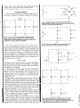
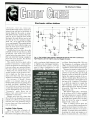
was vet-) happy to see my article,
"Starlight Synth" in the June 1988 issue of Hands -on Electronics. However,
the schematic you printed contained a
few errors.
In Fig. 1. B I should not go between
the collector and emitter of Q15. Instead, it should go between pin 14 and
I
I am looking for information on my
audio amplifier, made by the "Great
American Sound Co., Inc." of
Chatsworth, CA. There is no apparent
might simmodel number on the unit
ply be called "Son of Ampzilla."
I have attempted to contact the company, with no success. I need a parts
list and schematics for that unit, or a
current address of the manufacturer.
Thank you.
Randy E. Meyer
715 Park Avenue
So. Milwaukee, WI 53172
.
SORRY, No orders accepted outside of USA and
State
would like to know how to build a
voice -activated/recognition device. If anyone can help, please write to me.
Timothy Green
2034 Ocee Drive
Riverdale, GA 30296
-it
SHIPPING CHARGES IN USA AND CANADA
Clty
It might be fun to watch! But as you
may knots', the use of any electronic
device on planes is restricted, especially.
receivers. That makes using the jacket
on the plane a no -no in the first place.
So, if you've got one, pack it or leave
it at home.
Haves and Needs
Starlight Serenade!
BP132 -25 SHORTWAVE BROADCAST ANTENNAS
$5.50. Good
antennas can be inexpensive. Here's 25 different
ones ranging from a simple
dipole. through helical designs to a multi -band umbrella.
MAIL TO Electronic Technology Today Inc
PO Box 240
Massapequa Park NY 11762 -0240
Subtotal
explain that to Airport Security?
-W.M.S., Marina, CA
store.
reception.
Total price of merchandise
Shipping (see chart)
Odgen, IL
July, 1985 issues. Those magazines can
also be ordered through the Reprint Book-
BP136 -25 INDOOR
AND WINDOW ANTENNAS.... $5.50. If you
cant put up a conventional
antenna because of where
you live. one of these 25 designs is likely to solve your
problem and deliver great
$0.01 to $5.00 ... $1.25
$5.01 to 10.00 ... $2.00
$10.01 to $20.00 .$3.00
$20.01 to $30.00 .$4.00
-E.W.O.,
Making (Air) Waves
like your magazine, and I hope
you keep up the entry -level electronics
articles.
I have a question regarding the "Sonic
Jacket" featured in the "Gizmo/Bytes"
section in the July 1988 issue. It contains speakers, an amplifier, and a battery pack built into the jacket itself.
Can you picture a person trying to
I
I
se....
a.ntl
/f &,i.,
also.
Now I have people asking me about
repairing automobile radios and tape players with digitally synthesized PLL (all electronic tuning). I've also had requests
about cordless -phone repairs. Many repair shops tell people that the cost to
repair those units is prohibitive, and advise them to buy new equipment.
It seems a shame to junk those units
that look almost new. Can you recommend any books about servicing that
equipment? Where can I can obtain
them?
Our sister magazine, Radio -Electronics, ran a story on servicing cordless telephones in their May. June, and
Amateur Band
Acnala
25 15..,,a.
doing repair work for friends and relatives. When transistors came on the
scene, I took some courses and learned
how to service solid -state equipment
pin 7 of the 556 timing chip. Also in
Fig. I , S I should be between the positive lead from B1 and pin 14 of that
integrated circuit.
I hope that straightens out any problems your readers might encounter.
-Timothy A. Riggs
Zip
I am desperately in need of a schematic for a Teledyne 4- Channel Quad rasonic Radio Receiver, Model No. RA632.
I've tried Olson Electronics, who suggested write to Teledyne Corp., who
told me to try Cube Master -who seems
to have disappeared!
Robert K. Browne
9818 McKnight, NE
Albuquerque, NM 981 12
1
can even earn your Associate in
Applied Science Degree in Electronics Engineering Technology. Of
course, you set your own pace, and,
if you ever have questions or
problems, our instructors are only
a toll-free phone call away.
e first step
is yours.
To find out more, mail in the
coupon below. Or, if you prefer,
call toll -free 1-800-321-2155
(in Ohio, 1-800-523-9109).
We'll send you a copy of CIE's
school catalog and a complete
package of enrollment information.
For your convenience, we'll try to
have a representative contact you
CIE MAKES THE WORLD
OF ELECTRONICS YOURS.
Today's world is the world of electronics. But to be a part of it, you
need the right kind of training, the
kind you get from CIE, the kind that
can take you to a fast growing career
in business, medicine, science,
government, aerospace,
communications, and more.
cialized
training.
You learn best from a specialist,
and that's CIE. We're the leader
in teaching electronics through
independent study, we teach only
electronics and we've been doing
it for over 50 years. You can put
that experience to work for you
just like more than 25,000 CE
students are currently doing
all around the world.
tactical
raining.
You learn best with practical training,
so CIE's Auto-Programmed® lessons
are designed to take you step -by -step,
principle-by- principle. You also get
valuable hands -on experience at every
stage with sophisticated electronics
tools CIE -designed for teaching. Our
to answer your questions.
4K RAM Microprocessor Training
Laboratory, for example, trains you to
work with a broad range of computers in a way that working with a
single, stock computer simply can't.
rsonalized
training.
You learn best with flexible
training, so we let you choose from
a broad range of courses. You start
with what you know, a little or a
lot, and you go wherever you want,
as far as you want. With CIE, you
CIE
A HO-95
Cleveland Institute of Electronics
1776 East 17th St.,
Cleveland, Ohio 44114
YES! I want to get started. Send me my CIE school catalog including details about
the Associate Degree Program. I am most interested in:
computer repair
television/high fidelity service
medical electronics
telecommunications
robotics /automation
broadcast engineering
other
Print Name
Apt.
Addres,
City
Age
State
Zip
Area Code /Phone No.
Check box for G.I. Bulletin on Educational Benefits
Veteran
Active Duty
CIRCLE 8 ON FREE INFORMATION 2,ARD
MAIL TODAY!
11
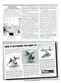
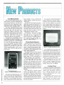
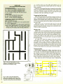
design concepts. and component identification are discussed, followed by basic
troubleshooting techniques. By understanding how printers should work, the reader
will be better able to localize the trouble when
they don't work.
Electronics Library
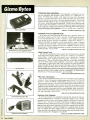
20 INNOVATIVE ELECTRONICS PROJECTS
FOR YOUR HOME
by Joseph O'Connell
Hobbyists might decide to build a project
because they can't buy it anywhere, because
it's cheaper to make it themselves, or just
for the fun of it. This 264 -page book has
projects in each of those categories -and
some that overlap. The emphasis is on
unique, yet practical devices that are timesaving and cost-efficient.
Readers learn how to make a portable
mini -refrigerator from a cooler, a solid -state
blanket controller, active mini -speakers with
built -in amplifiers, a fluorescent bike light,
a ringing -telephone alerter, and more. Each
chapter contains a description of the circuit,
construction details, photographs and diagrams, and a discussion on how to use the
circuit.
Complete parts lists accompany each project, and a separate chapter lists sources
for new and surplus parts and explains
when it is better to buy used parts. A chapter on construction contains advice on tools
and materials, soldering irons, test equipment, and various construction methods.
In addition to the 20 main projects, a chapter on electronics contains some simple circuits and helpful hints on circuit design and
modification.
20 Innovative Electronics Projects For
Your Home is available for $13.95 from Tab
Books Inc., Blue Ridge Summit, PA 172940850; Tel. 1- 800 -233 -1128.
CIRCLE 9$ ON FREE INFORMATION CARD
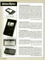
PRINTER TROUBLESHOOTING & REPAIR
by John Heilborn
Syndicated computer columnist John
Heilborn has written this book for intermediate to advanced computer users with a basic understanding of electronics. It provides
answers to the most common printer- repair
problems, and covers dot- matrix, ink -jet, and
laser printers.
Printer Troubleshooting & Repair begins
with a description of each type of printer
and how they work. Theory of operation,
12
Subsequent chapters contain detailed
troubleshooting and repair information for
each type of printer. Charts, schematics,
and component lists are included. The author
discusses tools and test equipment, soldering techniques, and guidelines and cautions
for making repairs. Each part of the printer
print heads, transport mechanisms, power
systems, logic and control systems -is discussed separately and in relation to other
parts.
This 194 -page book also includes a sec-
-
tion on preventive maintenance, to help readers prolong the lives of their printers. Two
useful appendices provide IC- pinout diagrams to facilitate the identification of the
input, output, power, and ground connections for logic -IC devices; and a listing of
printer manufacturers and suppliers.
Printer Troubleshooting & Repair (No.
22543) costs $19.95. It is available from
bookstores, computer stores, and electronics distributors, or from Howard W. Sams
& Company, 4300 West 62nd St., Indianapolis, IN 46268; Tel. 800 -428 -SAMS.
('IR('I.E,
95 ON E'REE.
INFORMATION ('ARD
QUATTRO: THE PROFESSIONAL
SPREADSHEET MADE EASY
by Lisa Biow
Quattro software offers a combination of
spreadsheet, database, and graphics that
is easy to use and is very powerful. This
600 -page book provides a thorough background in the basics of spreadsheet organization and design for readers who are new
to Quattro, or to spreadsheet software in
general.
Quattro: The Professional Spreadsheet
Made Easy begins with the fundamentals
of creating and using Quattro worksheets
entering and editing data, saving and retrieving worksheets, manipulating blocks of
data, rearranging and formatting worksheets,
and printing reports. With clear instructions
and hands -on exercises, readers quickly
learn to design a spreadsheet, modify data,
and use formulas.
More -advanced concepts and techniques
are also presented, including graphing, database design, macros, the use of functions,
and methods of customizing Quattro. There
is a complete chapter on the principles and
strategy of spreadsheet design. When those
concepts are applied to the specific corn mands and techniques presented in preceding chapters, the result is a sophisticated,
well- designed spreadsheet.
Four appendices contain an installation
-
guide, a summary of Quattro's 100 functions, helpful hints for Lotus 1 -2 -3 users
who are switching to Quattro, and a list of
commands.
Quattro: The Professional Spreadsheet
Made Easy is available for $19.95 from
Osborne McGraw -Hill, 2600 Tenth Street,
Berkeley, CA 94710.
CIRCLE $4 ON FREE INFORMATION CARD
ELECTRONIC HOBBYISTS HANDBOOK
by R.A. Penfold
As electronics becomes increasingly complex, the hobbyist is confronted with a tremendous amount of data. The Electronics
Hobbyists Handbook provides a useful collection of data for the amateur electronics
enthusiast, so that much of the data he needs
is available in a single source.
The book covers common component color codes, and details the characteristics
and pinouts of many popular semiconductor devices -including logic ICs, op -amps,
transistors. FETs, SCRs. triacs, diodes, rectifiers, and regulators. Several types of circuits are illustrated. including timers, oscillators, audio amplifiers, and filters. There
is a separate section on power supplies.
Circuit symbols, interface details. amateur and CB- frequency allocations are also presented in this 88 -page book.
Some knowledge of electronics is needed
to make use of the data, which is intended
for students, designers, and technicians, as
well as hobbyists.
The Electronic Hobbyists Handbook (order No. BP233) is available for $11.95 from
Electronics Technology Today, P.O. Box
240, Massapequa, NY 11762.
CIRCLE 97 ON FREE: INFORMATION CARD
UNDERSTANDING DATA COMMUNICATIONS,
SECOND EDITION
Edited by Gilbert Held
Data communications -the process of communicating information using binary signals
has become vital to the American economy,
and is rapidly gaining importance in homes
as well. This 291 -page book explains how
data -communications systems, and their various hardware and software components,
work.
Understanding Data Communications,
Second Edition covers the basic concepts
and principles of data -communications systems in general. Opening with a history and
overview, the book discusses data terminals,
messages and transmission channels, asynchronous and synchronous modems, interfaces, digital transmissions, fiber -optic and
satellite communications, protocols, and error control.
-
Tips are given for setting up a system to
communicate between a personal or professional computer and either another personal computer, a data -base service, or an
electronic -bulletin board. Information is included on architectures and packet networks,
concepts behind Word's features, and reinforces the concepts with do- it- yourself examples. Each chapter is divided into lessons that are illustrated with screen photos,
and ends with review exercises.
The 405 -page book gives a complete overview of Word's editing features and formatting commands; discusses general top Tics such as printing, merging, and various
options; and shows how to use advanced
features-outlines, tables of contents, spelling correction, indexes, and sorting -to pre-
ers, and power supplies.
Each item is illustrated with a photograph.
Specifications are provided, as well as a
description of each unit.
Several new items are featured in this
catalog. Those include a combination digital multimeter digital-storage scope with com-
network design and management, Integrated
Services Digital Network (ISDN), and the
Hayes modem -command set.
Using a text -book format, each chapter
begins with an introduction and concludes
with a summary of the material presented
and a self -quiz.
panion printer, a synthesized NTSC-tesV
sync-signal generator, a combination waveform monitor vectorscope, an AM /FM -stereo signal generator, and two battery powered NTSC -pattern generators.
pare business documents. The new features
in version 4, such as macros and advanced
document retrieval, are covered. Also included are special features for legal documents, desktop- publishing projects, text outlining, and windows.
For beginners, the book teaches basic
word -processing terms and describes in detail how to get started. The lessons build
on material presented earlier in the text, making it easy to advance. Readers with some
Word experience will find topics mentioned
briefly in the Microsoft Word manual elaborated upon in this book. Advanced users
will appreciate reference material throughout the book, particularly in the appendices.
Those appendices summarize editing
and formatting commands, mouse keyclicks,
and the Word Command Tree; and describe
The 1988 Short Form Catalog is free upon
request from Leader Instruments Corporation, 380 Oser Avenue, Hauppauge, NY
11788: Tel. 1- 800 -645 -5104.
Understanding Data Communications,
Second Edition is available for $17.95 from
Howard W. Sams & Company, 4300 West
62nd St., Indianapolis, IN 46268: Tel. 800428 -SAMS.
CIRCLE
56 ON FRF.F.
INFORSIATIOti ('ARI)
CIRCLE: 95 ON FREE INFORMATION CARD
MICROSOFT WORD MADE EASY,
THIRD EDITION
1988 SHORT FORM CATALOG
by Paul Hoffman
LEADER INSTRUMENTS CORPORATION
This book, which shows new Word users
how to handle that powerful word- processing program with skill and confidence, has
been revised to include all the features of
through 3 are
Word version 4. Versions
also covered.
Microsoft Word Made Easy explains the
This 4 -page brochure presents a cross section of Leader's line of more than 100
test and measurement instruments. It features oscilloscopes, professional video -test
equipment, signal generators, audio- and
video -service instruments, frequency count-
1
COMPUTER CHASSIS with POWER SUPPLY
rSgpo
r- t_a-.cu,e Sp,a- tue,
O,e
fo,ns', Natures
Mgr,
Duty PusT[ Case
. e. o D
r. r
,
,
Mnq.E or,,. a.loanwq e.ee,.ery Ia
Sr.,
-s.,:
i an ,:
ov,a
PC
NEW! IN ORIGINAL BOX!
$69.00
RL.RMOe Parr 5'-M-,. R.MI Bulbn
Nms.ous Cut Outs u R.. a, Iv cRnnnn-:
IEC
RECEIVER
.Ta
ran
Dq,
IO
W
Teavr
.a. PC
RCA COP
¿SC
Wort
,Ipr Rooms
err Cars.
m.rcue e.on
Pyç
two
,vAC
WRY.
Rased
NO
.
SliEhr
..,..
M all
[i :...
w.,M TNOUSANOS a Pen.
nw., ICY. o+ a,M,s,,,sss.
b
$89.95
rues'..
ao.
Why
nuVTpn
es'
PLEASE
nuno
may
.
5
IUD
Lall
VIM..
OP VISIT
an,
,.
...n.ro lawn.,.
Senn SO..
RS
G.. Rw.w Maw
cling E,aa.no
M,n,
Wi Cp
'NESS
1)215
ARE
Otis
REQUIRE A COMPUTER
COHIRC
(NOT AVNLABLE 150M HALTED
MEV CANNOT BE MAMJALLV
.
See
cz.
7
$31.95
$99.00
'0
Large Quantity Available
¿.
MSC
d
cONVENIENT LOCATIONS
Santa Rasa
1415C
ol
3500 RYDER ST.
SANTA CLARA, CA 95051
Santa.,
.'..
CA Reside'tO
Info Toll Free Order
Call
NOW! 408 -732 -1573 800 -4- HALTED
P.
,
CIRCLE 9 ON FREE INFORMATION CARD
.
,
1dß
XENON TUBE
1
long flashcube prepped
with 3 112' red and black
leads. Ideal for electronic
flash or strobe projects.
CATI FLT -3
2
for $1 00
N- CHANNEL
MOSFET
(
\
\\,
IRF -St
t
TO -220 case
511
CATI I RF
$t.00 each
10 for $9 00
T
LARGE QUANTITY
AVAILABLE
MAIL ORDERS TO:
ORDER TOLL FREE
ALL ELECTRONICS
800- 826 -5432
P.O. BOX 567
VAN NUYS, CA 91408
TWX5101010163(ALL
s
$600
'Or
Intermittent duty cycle. 240 ohm coll. Mounting flange
is
1/8" wide Solenoid body 11/2' X 1/2" X 1/2"
CATI SOL -34 $1 00 each
10 for $8 50
100 for $75 00
{Q
T
-232
un e ..
,e
Cmnpo0
A.
OEM MODELS
i
3 a X 7/8"
2 /a X
CAT* SSRLY -108 $9.50 each
10 for $85.00 25 for $175.00
50 for $300.00 100 for $500 00
BREAKOUT BOX
Two OP,<al Le
O weal wach,
25 amp carry
,,rrent. P.C. mount.
CATI PB -8
65c each
E
0
,
O,
switching.
CONTROL.5.5 - 10 Vdc
( will operate 3- 32Vdc)
240 Vac
LOAD: 10 Amp
$89.95
1mW Maw
Rated: 0.1 amp
t.
Murata Erie # PKB8 -4A0
alarm.
High
ondible
3 - 20 Vdc @ 20 ma.
t- high x 7/9" dia. i?T-- dd--iN
P C board mount.
CATI PBZ -84 $1 75 each
ELECTROL IS2161
ON r',
law Ia.
..., Parr S,.P
fvn Sw,a nno
top ?you G. am.E
,
-
r''
P.S.T.N.O. Push to
RELAY
I/4
IBM COMPATIBLE
' 360K
' 90 -DAY WARRANT'
,NIE f RFTM STORES IOW,
an
_-
S.
10 AMP SOLID STATE
TEAC FD -55B
DISK DRIVE
ross
V.
T
MDPL serles 3.4 x
2' gray rectangular key
reap
1
,OPnl
Is
Sd,-....
nmvac I.n,
T
PIEZO WARNING
DEVICE
24 VOLT D.C.SOLENOID
S
8
Comes
At
`
''
-.s:i
1-
Pow. COnroCTd
u,.,
$19.95
RAI TED SPELNLLTor
Una,
ARKET Srv, f
ANV
ELECTRONIC NEE
9
pea -w.u.1-a..no
sns
Sn,s
,es, Ponts for All aay Po
Great for 1h. EopsrImenterl
,o...o.E. TM,r,on
s^+
Caul
:uses Ene,wa, Cod
one 'OW Sn,
..
lED
Untested
Pions., Laser Disc Plays,
CoM,p G.a
a
EXTENDER
Mnr
Rqw Mas.
MIN
-°se+.0x..n
Ow° $29.95
CATALOG
runECTROnn
=OOPS
MOTHERBOARD
DorI.TIASC,IEmebE. ANSI CrW Sn,
S,anEarelBM Colas
s. +.
AT /XT 3 -SLOT
--
,
C,.P Co-slow S.o..'.,
Crystal Carmel
r., sa. s-ana
c,..
ó
lan a,
r"''-'-MV
PAGING
f
5.p.
r
DISPLAY
HALF HEIGHT EXTERNAL
DRIVE ENCLOSURE
An,.fn law PM. Lau
AT -XT-
'
$yy,
Posse,
LabCard for IBM
FREE
ouDe ne
new Orw
Cures arel I Ostrow MpE Dnve
2
ITT PUSH
BUTTON
SEND FOR
spec/a1[/es co.
,M,.
'
am ELECTROAICS CORP.
®Halted
ELECTRONIC)
OUTSIDE THE U.S.A.
SEND $1.50 POSTAGE
FOR A CATALOG!!
CIRCLE
5
INFO: (818)904.0524
FAX: (818)781 -2653
MINIMUM ORDER $10.00
QUANTITIES LIMITED
CALIF. ADD SALES TAX
USA: $3.00 SHIPPING
FOREIGN ORDERS
INCLUDE SUFFICIENT
SHIPPING. NO C.O.D.
ON FREE INFORMATION CARD
!oIII
13
BUILD -IT BOOKS
FOR EXPERIMENTERS
BP106- MODERN OPAMP PROJECTS
Modern Op An
....
Project
$5.75. Wide range of build
it
-
projects that use op-
amps. Easy to build board
layouts provided for most A
variety of projects of all
kinds are included.
Ner
#223- PROJECTS
....
USING THE CA3130
$5.00. 50 different ways to
put this op -amp to work in-
cluding audio.
RF,
Electronics Library
how to prepare the Word program, use other
programs with Word, and alter printer drivers; and present the answers to the review
exercises.
Microsoft Word Made Easy, Third Edition costs $18.95, and is available from
Osborne McGraw -Hill, 2600 Tenth Street,
Berkeley, CA 94710.
CIRCLE 96 ON
FRF:F: INFORNLNFION
('ARI)
test
equipment. household and
miscellaneous projects.
EXPERT SYSTEMS AND ARTIFICIAL INTELLI-
GENCE: APPLICATIONS AND MANAGEMENT
IC MARaMet
4
BP44 -IC 555 PROJECTS.... $5.95. Included
are basic and general timer
circuits. automobile and
model railroad circuits.
alarms and noise makers.
as well as a section on 556.
558. and 559 timers.
5o
,'224
50 CMOS IC
PROJECTS
ato/ IC
111.
55.25.
These ICs are suitable for
an extraordinary range of
applications. This book
shows you just how much
you can do with them
Second Book of
CMOS IC
BP59-2ND BOOK OF
CMOS IC PROJECTS....
$5.50. Still more ways to
use these versatile devices.
None of these projects overlap those in book #224.
The pair make a wonderful
circuit reference set
Projct
BP84- DIGITAL
MOW IC
IC b.
55.50.
Both simple and more advanced projects to help the
PROJECTS
a
knowl-
edge of the workings of digital circuits. A number of
board layouts are included
MAIL
TO
PO Box 240
Massapequa Park. NY 11762 -0240
SHIPPING CHARGES IN USA AND CANADA
$1.25
$2.00
$3.00
$4.00
$30.01 to $40.00 $5.00
$40.01 to $50.00 $6.00
$50.01 and above $7.50
SORRY. No orders accepted outside of USA and
Canada
in
o
O
cc
O
tif
w
z
price of merchandise
Shipping (see chart)
Subtotal
Sales Tax (NYS only)
$
Total Enclosed
$
$
$
Address
iCity
L
14
$
Name
p
State
Bartee
This 304 -page book is a collection of essays written by leading authorities in Artificial Intelligence (AI). It highlights the applications of Al in finance, communications,
space, and military systems. Aimed at the
professional -level business person, analyst,
or computer scientist working with expert
systems or other Al disciplines, the book
thoroughly explains problem solving, knowledge representation, and natural -language
processing.
Expert Systems and Artificial Intelligence:
Applications and Management presents an
overview of the basic principles of AI, examines current applications in several fields,
and discusses ongoing research and future
applications. The book also presents valuable insights into the history and development of artificial intelligence.
Priced at $39.95, in hardcover only, Expert Systems and Artificial Intelligence: Applications and Management is available at computer stores, bookstores, electronics dis-
CIRCLE
Electronic Technology Today Inc.
$0.01 to $5.00.
..
$5.01 to 10 00
$10.01 to $20.00
S20.01 to $30.00
C.
tributors, or directly from the publisher, Howard W. Sams & Company, 4300 West 62nd
St., Indianapolis, IN 46268; Tel. 800-428 SAMS.
....
reader develop
Edited by Thomas
Zip
95 ON FREF.
INFORMATION ('ARI)
IBM PS/2 HANDBOOK
by Richard Dalton with Scott Mueller
IBM's Personal System; 2 (PS /2) computers
are redefining the personal computer market. Not simply another new computer, PS/
2 is a family of new machines, monitors,
printers, and a desktop-publishing package.
The IBM PS /2 Handbook is a comprehensive guide to each of the new machines and
components. It details how the new systems perform better than previous IBM computers, and explains the various audiences
for the different models.
The book explains how the reader can
benefit from the PS /2. It describes the technological breakthroughs behind the system,
including the new system -board design,
MCGA and VGA graphics, and Micro Channel Architecture, and how they work to bring
the user unprecedented power.
For people considering the purchase of
a PS. 2, IBM PS /2 Handbook describes the
innovative features that distinguish each particular machine, from the low-end Model 25
to the high -powered Model 80. The book's
checklists also help readers determine which
machine best suits their needs.
Readers who already own a PS /2 can learn
how to realize their system's maximum potential. The differences and similarities of
the new OS/2 and PC DOS 3.3 operating
systems are explored, to aid readers in the
selection of software and hardware products that will best meet their PS 2 needs.
The book also describes how to communicate and exchange data between a new PS/
2 and an existing PC, with a minimum of
difficulty.
IBM PS/2 Handbook contains 358 pages,
and costs 19.95. It is available from Que
Corporation, P.O. Box 90, Carmel, IN 46032;
Tel. 1- 800 -428 -5331.
CIRCLE
94 ON FREE
INFORMATION CARD
EXPERIMENTS WITH EPROMS
by Dave Prochnow
Erasable Programmable Read -Only Memory devices ( EPROMS) are dual in -line packages capable of holding any user-supplied
programming in a nonvolatile fashion -yet
they can be quickly erased at the user's
discretion, and reprogrammed to perform
a different function. Virtually any design that
uses microprocessor control or requires external data for its operation can be easily
modified to accept EPROM programming.
Incorporating EPROMs into digital circuits
isn't difficult
you have an EPROM
programmer, an EPROM eraser, and prac-
-if
tical instructions. Experiments with
EPROMS provides all three. The book begins with a detailed explanation of underlying theory, including discussions of digital memory, binary codes, mathematics,
and logic, then goes on to desscribe fifteen
EPROM projects, including plans for several programmers and erasers.
Other projects featured in this 230-page
book are a Boolé s Box, a keyboard encoder,
a ROM drive, speech and music synthesizers, and an EPROM -program tester. The
step -by -step plans give home -electronics.
robotics, and computer experimenters hands on understanding of how EPROMs work.
Complete specifications and pin -outs for
popular PROMs, EEPROM5, and
EPROMs in current use are included in Experiments with EPROMS. The book also
explores commercially -available programmers and erasers, and provides an over19
CABLE-TV
view of alternate memory technologies. Although the book is aimed at intermediate
to experienced hobbyists, three appendices- building an EPROM project, IC data
sheets, and a list of suppliers-provide guidance for beginners, and helpful tips for all
readers.
Experiments with EPROMS costs $16.60
in paperback or $24.95 in hardcover, from
Tab Books Inc., Blue Ridge Summit, PA
17294 -0850; Tel. 1- 800 -233 -1128.
CIRCLE
98 ON FREF.
AMYONE S ICES
pR
OAR WHOLESALE
RETAIL
T
ADVERTISE0
BONANZA!
INFORMATION ('ARD
AN INTRODUCTION TO ANTENNA THEORY
ITE M
by H. C. Wright
When any conducting body is exposed to
a radio wave, it will have electrical currents
induced into it. Conversely, any conductor
carrying currents will radiate. Thus, many
common objects can be used as antennas.
The experimenter can test his ideas and
innovations, particularly with TV and CB wavelengths, with little more than bent copper
wire.
An Introduction to Antenna Theory covers the basic concepts relevant to receiving
and transmitting antennas. This heavily illustrated book emphasizes the mechanisms
involved, and minimizes the mathematics
used.
The 86 -page book begins with a definition
of the antenna and general wave -motion.
It discusses electromagnetic waves, antenna
efficiency, resistance to radiation, complex
impedance, reciprocity, directionality, and
parasitic elements. It describes several types
of antennas -including simple transmitting,
frame, helical, slot, dielectric -clad, microwave, long -wire, travelling -wave, superconducting, and active antennas.
An Introduction to Antenna Theory (order No. BP198) is available for $8.95 from
Electronics Technology Today, P.O. Box
240, Massapequa, NY 11762.
CIRCLE
97 ON FREE
INFORMATION CARD
Ouantlry
TOTAL
PRICE
Each
SUBTOTAL
Shipping Add
California Penal Code 9593 -D forbids us
from shipping any cable descrambling unit
to anyone residing in the state of California
Prices subject to change without notice
$3.00 per unit
COD & A d
Cards -Add 5%
59b
TOTAL
PLEASE PRINT
ci
z
Name
Address
o
u
City
W
Phone Number
Zip
G Money Order
Acct if
By Eric Alderman
Price
Output
Channel
Item
Cashier's Check
MICROSOFT WORD:
lo OR
MORE
'CALL FOR AVAILABILITY
State
THE COMPLETE REFERENCE
i
UNIT
COD
(
)
Visa
m
f
i Mastercard
Exp. Date
ú
d
Signature
FOR OUR RECORDS
Written for all Microsoft Nord users. this
comprehensive guide contains detailed listings of all functions and commands. The
new features of Version 4.- revision marks,
document retrieval. line and box drawing,
paragraph borders. remappable function
keys, and its powerful macro language
are included.
Microsoft Nord: The Complete Reference
is divided into three sections for easy access to information. It begins with an introduction to the Word's basic features, including its displays and menus, editing, and fin
-
-
I, the undersigned.
DECLARATION OF AUTHORIZED USE
that all products purchased. now and in the future. will only
authorization Iron local officials or cable company officials in
state laws FEDERAL AND VARIOUS STATE LAWS PROVIDE
PENALTIES FOR UNAUTHORIZED USE.
Dated
u
do hereby declare under penalty of pequry
be used on cable TV systems with proper
accordance with all applicable federal and
FOR SUBSTANTIAL CRIMINAL AND CIVIL
m
?
ó
>A
Signed
Pacific Cable Company, Inc.
73251/2 RESEDA BLVD., DEPT. #H10
(818) 716 -5914
RESEDA, CA 91335
No Collect Calls
(818) 716 -5140
IMPORTANT: WHEN CALLING FOR INFORMATION
Please have the make and model
#
of the equipment used in your area. Thank You
15
Electronics Library
ishing documents. Novices as well as experienced Nord users will find the alphabetical
reference section to be a quick, convenient
way to locate commands and features. Each
entry begins with a description, and then
explains the steps followed to use the command or features. Part 3 is a guide to advanced features, such as style sheets, glossaries, macros, tables and indexing, outlining, and columns. There are also appendices covering installation, keyboard and
mouse references, windows and pageview
features, and the differences between Version 3 and Version 4.
Microsoft Nord: The Complete Reference
contains 554 pages, and is available for
$24.95 from Osborne McGraw -Hill, 2600
Tenth Street, Berkeley, CA 94710.
CIRCLE 96 ON FREE INFORMATION CARD
PRACTICAL MIDI HANDBOOK
By R.A. Penfold
The Musical Instrument Digital Interface
(MIDI) is a means of swapping information
between suitably -equipped, electronic musical instruments, and is often used for computer control of instruments. Its main advantage is that it is a true standard, adopted
by many manufacturers-so that any instrument equipped with MIDI sockets will work
with any other piece of MIDI equipment, from
any manufacturer.
MIDI has been surrounded by misunderstanding, however, and the highly technical user manuals accompanying the
equipment often add to the confusion. The
Practical MIDI Handbook is intended to clarify things for the reader. It is aimed at musicians, technicians, and enthusiasts who
want to explore the capabilities of MIDI, but
are prevented from doing so because they
have little prior knowledge of electronics or
computers.
The basics of MIDI are explained, including such things as interconnecting a system, and why MIDI is needed at all. Most
of the book is devoted to an explanation of
what MIDI can do-and how to get the most
from it. The Practical MIDI Handbook covers the fundamentals of control codes, describes the types of equipment and software currently available, and explains how
systems can be tailored to meet individual
requirements.
While the main emphasis is on actually
using MIDI systems, theory and technical
details are included as well. Full details of
the MIDI -code numbers are provided for
those who wish to do their own MIDI programming. Also included is advice on deciphering the technical material in the owner's
manuals.
16
The Practical MIDI Handbook (order No.
PCP103) contains 150 pages, including a
glossary of terms. It is available for $11.95,
including shipping, from Electronics Technology Today, P.O. Box 240, Massapequa,
NY 11762.
('IR('I.F:
97 ON FRF.F.
INFORMATION ('ARD
LEARNING ELECTRONICS: THEORY AND
EXPERIMENTS
by R. Jesse Phagan and
William Spaulding
This comprehensive guide combines electronics theory, math, and hands-on experience with computer -aided instruction using
the Commodore 64'128. No previous electronics or computer experience is required
for understanding the material presented in
this book.
The book's main emphasis is on student managed learning; its key is the involvement
of the student in the learning process. Each
chapter -after the first two introductory chapters -has a computer program to quiz the
student on the information presented. Other
programs provide practice and experience
with ohmmeters, voltmeters, ammeters, and
oscilloscopes.
Learning Electronics: Theory and Experiments explains the fundamentals of electronics, including the math necessary to support each concept. Some of the topics covered are meters, DC and AC circuits, soldering techniques, basic hand tools, and
engineering notation.
Projects and experiments illustratethe principles that are presented throughout the text,
and practice exercises in mathematics are
included. Sample exams and answers are
also provided. Computer programs, which
graphically illustrate the electronic concepts
and mathematical relationships, are supplied.
Learning Electronics: Theory and Experiments costs $16.95 and is available from
Tab Books Inc., Blue Ridge Summit, PA
17294 -0850; Tel. 1- 800 -233 -1128.
CIRCLE
98 ON FREE
INFORMATION CARD
CRASH COURSE IN
ELECTRONICS TECHNOLOGY
By Louis
E.
Frenzel, Jr.
this book seems familiar at first glance,
thafs because its author, Louis E. Frenzel,
Jr., has been writing learning courses for
Hands -on Electronics for years. Like his
articles, Crash Course in Electronics Technology is a tutorial with a step -by -step format. It will help hobbyists, students, and laypersons learn the basics of electricity and
electronics.
Crash Course in Electronics Technology
is a complete self -study course in the funIf
damentals of electronics. Written at the technician level, it can be used alone, as a
supplement to a regular classroom course,
or as a refresher course on a particular
subject.
A brief introduction to electricity is followed
by a discussion of circuit basics and electronic devices. The book continues with a
presentation of electronic communication,
controls, test equipment, and troubleshooting techniques. Some of the other topics
that are covered in the text are magnetism,
resistors, inductance and transformers, capacitors, diodes, transistors, amplifiers and
op -amps, amplitude and frequency, and
pulse techniques.
Everything is presented in a self -paced,
instructional format. There are many clear
and informative illustrations, numerous examples that help enhance understanding,
and each chapter concludes with a self-test
review of the material.
Crash Course in Electronics Technology (order No. 22494) costs $21.95, from Howard
W. Sams & Company, 4300 West 62nd St.,
Indianapolis, IN 462ís $21.95, from Howard W. Sams & Company, 4300 West 62nd
St., Indianapolis, IN 46268; Tel. 800-428 SAMS.
CIRCLE
95 ON FREE
INFORMATION ('ARD
RADIO'S FIRST TWO DECADES
Consisting of selections from Radio Start
to Finish -originally published By Thomas
Y. Crowell Coin 1942-Radio's First Two
Decades is an informative journey back in
time. Whether you can remember the early
days, or are a member of the newer generation of radio enthusiasts, this book tells
an exciting story of the pioneers in the development of radio.
Beginning with Marconi'swirelessexperiments in 1895, Radio's First Two Decades
describes the earlier discoveries of Maxwell
and Hertz, upon which Marconi based his
experiments. The story of how Marconi
spanned the ocean is told, illustrated with
photographs of some of the actual equipment used. The book tells of Fessenden,
the first man to transmit the human voice
By wireless; DeForest, the developer of the
audion, or vacuum tube; and those men
whose visions led to the beginning of broadcasting. It ends with the start of radio as
we know it -the establishment of station
KDKA, and the first public broadcasts of
sports, music, and political events to an eager
public.
Radio's First Two Decades (order No.
RFTD) costs $4.75, including shipping. It
is by mail order available from Electronics
Technology Today, P.O. Box 240, Massapequa, NY 11762
CIRCLE
95 ON FREE
INFORMATION ('ARI)
A
2141
Science ßricl:
THE GRAVITY
OF THINGS
A team of scientists will travel to Greenland in July to
make some of the most sensitive geophysical measurements
ever made of the Newtonian gravitational constant, and to test
a new theory that a fifth, yet undiscovered, force may exist in
the universe.
The experiment is designed to detect and measure possible
variations in the gravity constant over distances in excess of
300 feet, far beyond the laboratory measurements of gravity
that are generally limited to lengths of a few inches. The
discovery of gravitational variations would have a significant
impact on several branches of modern physics, and would
require the recalculation of the masses of planets and stars.
Geophysicists Mark A. Zumberge, from the University of
California, San Diego, Institute of Geophysics and Planetary
Physics at the Scripps Institution of Oceanography, and Mark
E. Ander, from the University of California, Los Alamos
National Laboratory, will lower a gravity meter down a hole
bored into the Greenland ice cap to accurately measure the
gravitational constant first determined by Sir Issac Newton
more than 300 years ago. The universal constant is commonly called "big G" by physicists to distinguish it from
local gravity, "little g ", which varies continually with relation to the surrounding mass.
The Newtonian gravitational constant, G, is one of the
most important and least well determined of fundamental
physical constants. "If the effective gravitational constant
can be proved to be dependent upon distance, it will mean
that a fifth force exists in nature," commented Ander. Such a
finding could assist physicists in the pursuit of a unified field
theory that could tie together the known forces of gravity and
electromagnetism and the concepts of strong and weak
forces -two factors of nuclear particle physics. It will also
profoundly effect other branches of physics such as general
relativity, astrophysics, and cosmology.
During the experiment, the research team will measure the
changes in the force of gravity at different depths within the
remote location known as DYE 3, where the United States, in
cooperation with the Danish government, operates an AirForce radar station. The gravity meter will be lowered down
the borehole to a depth of about 5,000 feet and then raised in
300-foot intervals where measurements will be taken. About
a dozen readings will be taken as the instrument moves up the
hole. Calculations from these measurements will determine
the value of the force of gravity inside the hole as a function of
the position of the instrument in the huge ice sheet. The
gravitational effects of the earth beneath the ice will be
factored out of the final calculations.
The investigation is supported by the NSF Divisions of the
Polar Programs and Physics, Los Alamos National Laboratory, and additional funding from Amaco Production Company,
Mobil Research and Development company, and the Air
Force Geophysics Laboratory in Bedford, Massachusetts.
(Continued on page 106)
IF ANDERSON HAD USED
MCM QUALITY
PARTS...
... he
-
might still be in business today! But he
he isn't!
and
didn't
Maybe he forgot that in a service business like
his, quality is just as important as finding the best
price. If he had been buying his parts from MCM,
he would have discovered that we offer some of
the most competitive prices in the industry on
nearly 11,000 of your most often needed items .
and they're all high -quality products that perform
as promised ... every time! Or perhaps he was
dealing with a supplier that couldn't deliver the
when he needed them. If he
parts he needed
had been buying from MCM, he would have found
that almost everything we offer is in-stock, ready
to ship within 24 hours.
Don't let what happened to
Anderson happen to you!
.
.
-
Order your FREE MCM
Electronics catalog today and
discover what a difference we
can make in your business!
For your FREE copy,
call TOLL -FREE
1- 800 -543-4330
In Ohio, call 1- 800 -762-4315
In Alaska or Hawaii, call 1-800 -858 -1849
MCM ELECTRONICS
PARK DR.
858
E. CONGRESS
CENTERVILLE, OH 45459 -4072
A PREMIER Company
SOURCE NO. HO -19
CIRCLE 14 ON FREE INFORMATION CARD
17
D
DDEN
True RMS Multimeter
The Fluke hï handheld digital multimeter offers a powerful combination of
measurement functions, including frequency, duty cycle, capacitance, minimum /maximum /average recording,
MIN MAX Alert, and Input Alert.
The Input Alert safety feature warns
the user when the leads are connected to
the current jack while the meter is selected for voltage or resistance. The
MIN MAX Alert pinpoints intermittent
failures by signaling the user with a
short beep when a new minimum or
maximum value has been recorded.
The Fluke 87's analog display, which
is updated 40 times per second, is a
high -resolution pointer. The display can
be back lit, and has a user-selectable
411 -digit (20,000 count) mode, in addition to its standard 33/4 (4000 count)
digital display. A true RMS multimeter,
the Fluke 87 also features a peak MIN
MAX recording mode, with -ms response, that is ideal for capturing transient events.
1
been removed. It has a 20 -kHz ACvoltage response, and DC accuracy to
within 0.1 %.
The Fluke 87 is overload -protected to
1000 volts in ohms and diode test. It is
EMI -shielded, and is packaged in a
splash- and dust -proof case, with a protective holster. The case's unique flexible- rubber stand allows the meter to be
hung from doors or pipes, as well as
being used as a normal tilt -leg.
The Fluke 87, which carries a three-
year warranty, will be available
November 1st, for a suggested retail
price of $259.00. For further information, contact John Fluke Mfg. Co.,
Inc., P.O. Box C9090, Everett, WA
98206; Tel. 800 -443 -5853.
26 -Inch Monitor/ Receiver
Yamaha Electronics Corporation's
Model YM -265S video monitor/receiver has a high -resolution 26 -inch
screen, infrared-remote control, Separate Audio Program (SAP), Multichannel Television Sound (MTS) stereo, and
Super -VHS compatibility.
The YM -265S has a high- contrast
tinted CRT, comb -filter circuitry, a
black- matrix screen, and 560 lines of
horizontal resolution -resulting in a
CIRCLE 40 ON FREE INFORMATION CARD
The digital multimeter features a relative (zero) mode, has Touch Hold capability, which senses a stable reading
and locks it on the display, for convenient viewing after the test leads have
18
It can receive standard broadcast -TV
sound, MTS stereo, and SAP. LED indicators make sound -source selection
easy. An audio -enhancer circuit makes
even a mono signal sound impressive.
Slim speakers, built in to the bottom of
the unit's front panel and driven by a
2.5 -watt amplifier, further enhance its
sound.
sharp image. S -VHS compatibility is
achieved through a new S-connector.
The unit has antenna inputs for reception of all VHF, UHF, and major cable
channels -I42 channels in all -and
accurate reception is assured by the frequency- synthesized tuner. The numeric
keys on the remote control provide direct access to any channel, or the up/
down tuning controls can be programmed to scan, skipping over unused
channels.
The YM- 965S's infrared -remote
control also operates power, volume,
and muting. The unit's input -source
switching, and digital -clock and timer
display, can also be controlled remotely.
An on -screen channel and time display
can be switched on using the remote or
from the front panel.
CIRCLE 41 ON FREE INFORMATION CARD
The YM -965S also has external optional- speaker outputs powered by a 5watt amplifier, and rear-panel audio outputs for connection to a stereo system.
Two sets of audio and video terminals, a
monitor terminal. and an RF connector
provide easy connection to other components in an audio/video system.
The suggested retail price for the
YM -965S is $899.00. For more information, contact Yamaha Electronics
Corporation USA, 6660 Orangethorpe
Avenue, Buena Park, CA 90620.
Cordless Phone
The EA( ursion 5100 is an inexpensive.
full -featured portable- cordless phone.
It has a battery-low indicator; LEDs for
power, in -use. and charge: a flash button; a 750-foot operating range: tone/
pulse -switchable dialing; and is hearing -aid compatible.
The telephone's call bar acts as a one way pager. When the call bar on the
base is pressed. the handset buzzes.
alerting the person with the handset.
Now from
NRI comes
... anywhere!
the first course of its kind
Learn to use, program, and service today's
digital electronic music equipment as you
,G
build your own computer- controlled
music center
o
1.1
to take advantage of today's opportunities
in electronic music technology.
Now NRI puts
you at the heart of
the most exciting application
of digital technology to date! With
NRI's new at -home training in Electronic
Music Technology, you get hands-on
experience with the equipment that's
revolutionizing the music industry-Atari
ST Series computer with built-in MIDI
ports, Casio CZ101 digital synthesizer with
advanced MIDI capabilities, and ingenious
MIDI software that links computer keyboard to synthesizer keyboard -all yours
to train with and keep.
This year. over $1.5 billion worth of digital electo )nic music instruments-keyboards, guitars.
drum machines. and related equipment -will be
sold in the U.S. alone. Who's buying this new -tech
equipment? Not just progressive musicians and professional recording technicians, but also thousands
of people who have never touched a musical instrument before. And there's good reason why.
Something called MIDI (Musical Instrument
Digital Interface) has suddenly transformed musical
instruments into the ultimate computer peripherals
... and opened up a whole new world of opportunity
for the person who knows how to use, program, and
service this extraordinary new digital equipment.
Now NRI's breakthrough Electronic Music
Technology course puts you at the forefront of this
booming new technology with exclusive hands-on
training built around a MIDI- equipped computer.
MIDI synthesizer. and MIDI software you keep.
Dynamic New Technology Opens Up New
Career Opportunities for You
The opportunities are unlimited for the person
who's trained to take advantage of today's electronic music phenomenon. Now you can prepare
for a high-paying career asa studio technician.
sound engineer. recording engineer, or road
technician ... even start your own new -age
business providing one-stop sales and service for
musicians. technicians, and general consumers
alike. Or simply unleash your own musical
creativity with the breakthrough training and
equipment only NRI gives you.
Only NRI Gives You an Atari ST Computer,
Casio Synthesizer, and Innovative MIDI
Software You Train With and Keep
The Atari ST Series computer included in your
course becomes the heart of your own computer controlled music center. With its tremendous
power. superior graphics capabilities. and built -in
MIDI interface. the 16/32-bit Atari ST has almost
overnight become the computer of choice for
today's most knowledgeable electronic musicians.
The Casio CZ101 digital synthesizer, also included
in your training, is the perfect complement to your
Atari ST. The polyphonic, multitimbral CZ101which stores up to 32 voices intemally- "communicates" with your ST computer through MIDI.
bringing life to virtually any sound you can imagine.
Plus, you get ingeniously designed MIDI software
that opens up amazing new creative
Plus. even if you've never been involved with
music before. NRI gives you enough basic training
in music theory and musical notation to appreciate
the creative potential and far-reaching applications
of today's electronic music equipment.
Send Today for Your FREE Catalog
For all the details about NRI's innovative new training, send the coupon today. You'll receive a complete catalog describing NRI's Electronic Music
Technology course plus NR1 courses in other high tech. in -demand electronics fields.
lithe coupon is missing. write to NRI School of
Electronics, McGraw-Hill Continuing Education
Center, 3939 Wisconsin Avenue, Washington. DC
20016.
r- AIM School of Electronics
and technical possibilities ... you
actually build your own 4 -input
I
audio mixer /amplifier... and you
test the electronic circuits at the
core of today's new-tech equipment
with the hand-held digital multi meter included in your course.
No previous experience
With your experienced NRI instructor always
available to help. you master the basics of electronic
theory step by step, gaining the full understanding
of electronics that's now so essential for technicians
and musicians alike. You move on to analyze sound
generation techniques, digital logic, microprocessor
fundamentals. and sampling and recording techniques... ultimately getting first -hand experience
with today's explosive new technology as you
explore MIDI. waveshaping, patching, sequencing.
mixing. special effects. and much more.
1,Grae' -hill Continuing Education Center
3939 Wisconsin Avenue
Washington. DC 20016
?CHECK ONE
FREE CATALOG ONLY
Computers and Microprocessors
Basic Electronics
Electronic Musk Technology
TVIVideolAudio Servicing
necessary-in electronics
or music!
Name
No matter what your background.
NRI gives you the skills you need
ra,
or,,,.,.
Age
1+7n,,
!.,:treet
Lit!
i aensbted
air
State
by the A,.eredmog Commission
d the Nat, ,cd
16
me Stud, C,
ri
18 108
21
NEW PRODUCTS
The Excursion 5UU's battery pack is
consumer replaceable. It also has a replaceable antenna, further reducing the
need for manufacturer service or repairs. The new antenna screws on for
simple installation.
The Plus -Board units have two solderless breadboards with tie points laid
out on a 0.1 -inch x 0.1 -inch matrix.
Those breadboards accept all DIP sizes
and a wide variety of discrete components with lead diameters of up to .032 inch. There are 1.680 plug -in tie points
on each hoard, accommodating up to
eighteen 14 -pin DIPs. Mounted to an
aluminum- ground plane. the hoards are
ideal for high - frequency and highspeed /low-noise circuits. Circuits are
protected by a short-proof power supply
and fused -transformer primaries.
CIRCLE 43 ON FREE INFORMATION CARD
CIRCLE 42 ON FREE INFORMATION CARD
The ash -tone cordless phone is desk x
or wall- mountable. It is compact
5 inches -and the handset weighs only
6% ounces.
The Excursion 5(X), complete with
line cord and instruction book, has a
suggested list price of $79.(0. For further information, contact Northwestern
Bell Phones. 9394 West Dodge Road.
Suite 1(X). Omaha. NE 68114.
-9
Solderless Breadboarding Labs
3M Electronic Products Division's
self- contained. solderless breadboarding labs are now available with remova-
ble circuit -board assemblies. That
design allows engineers and technicians
to perform multiple circuit projects
-
one per hoard -using a single
Powerace Plus- Board. In classroom
use, the removable circuit -board feature
permits students to keep their individual projects on their own hoards.
The Models 202 and 203 (part No.
923202 and 923203) have a suggested
retail price of $175.05 each. Further
information is available from local 3M
22
Street, Phoenix, AZ 85044; Tel.
602 -968 -6231.
Fiber-Optics Experimenter Kit
Jameco's JE3I5 Advanced Fiber Optic Kit is designed as an educational
device. It gives students, hobbyists,
and engineers both a hands -on experience with fiber optics, and a better understanding of how fiber- optics technology really works.
The JE3I5 includes separate transmitter- and receiver-circuit boards, and
an on -board oscillator for easy circuit
testing. It accepts analog- or TTL-input
signals. and can process multiple analog and digital signals that have been
combined together previously. Its frequency range is 40 Hz to 6.5 kHz, and
its circuitry includes a 555 timer chip,
LMI458N op -amp ICs, and an
MFOD73 photo transistor.
Electronic Specialty Products distributors, or contact: Electronic Specialty Products, 3M Electronic Products
Division. 9325 Progress Parkway, P.O.
Box 540. Mentor, OH 44060; Tel.
800 -321 -9668 (216 -354 -2101 in Ohio).
Tool Kit
Jensen has improved their popular
JTK-79 Electro- Mechanical Tool Kit.
designed for the performance of a wide
variety of electronic - and mechanicalrepair tasks.
The kit contains a I4 -piece socket
set, a 7 -piece jewelers -screwdriver set.
a 10 -piece hex -key set, 4 screwdriver
CIRCLE 44 ON FREE INFORMAFION CARD
The advanced fiber-optics experimenter kit, complete with step -by-step
instructions, theory of operation, and
tutorial information. clearly demonstrates the principles of fiber-optic design. Model JE3I5 includes fiber-optic
cables and connectors, and costs
$29.95. For more information. contact
Jameco Electronics, 1355 Shoreway
Road, Belmont, CA 94002; Tel.
The Powerace Models 202 and 203
each come with one removable circuit
board. Additional hoards can be purchased separately. Those models, as
well as the entire Powerace line of
breadboarding labs, feature internal
power supplies, logic monitors, a clock
generator. data -pulse sources. logic level switches, pulse generator, and
pulse detection with memory.
blades, a full -size handle. a wire- stripper/cutter, assorted pliers, and more.
Tools are held in a compact, 7- x 9- x
2-inch padded, zippered case. A Velcro
snap closure can hold an optional Beckman DM73 Meter.
The JTK -97 costs $79.99. For more
information and a free catalog, contact
Jensen Tools Inc., 7815 South 46th
415 -592 -8097 for orders only,
415 -592 -8121 for all other inquiries.
CIRCLE 44 ON FREE INFORMATION CARD
VHF Marine Radio
Kellwood's I KM -407 VHF marine
radio is designed for durability and reliable performance in the marine environment. Its high -impact, corrosion-
FREE!
resistant plastic case covers a die -cast
metal chassis. A large heat sink protects
the components from vibration and
damage.
The compact TKM -407 provides 25
watts of power output. For use on FCC restricted channels, the I -watt low power position can be used. It has a
large LCD for optimum readability in
sunlight, and is illuminated for night
viewing. The display can be adjusted
with a dimmer switch. The front mounted speaker is water resistant.
üiié (`
CIRCLE 45 ON FREE INFORMATION CARD
All U.S., Canada, and International
Marine channels are factory -programmed. The TKM -4077 also re-
ceives up to ten weather channels, and
can store as many as 30 other channels.
The radio has a dual -watch feature that
monitors Channel 16 for approximately
a half second every 2 seconds, allowing
the user to remain constantly in touch
with Channel 16 regardless of the channel being used.
The TKM -407 has three scanning
modes: Dial scan for all channels,
memory scan for the 30 memory channels, and an all weather-channel scan.
With mounting bracket and water -resistant microphone, the TKM -407 has a
suggested retail price of $599.99. An
optional flush -mount kit is also available. Further information can be obtained from Kenwood U.S.A. Corporation, Communications & Test Equipment Group, 2201 E. Dominguez St.,
Long Beach, CA 90810: Tel.
213- 639 -4200.
Compact AC Line -Voltage
Monitor
Dl Products' AC line -voltage
New Catalog of
Hard-To-Find
Precision Tools
r"""wCIRCLE 46 ON FREE INFORMATION CARD
prong plug molded into its case, allowing it to be inserted directly into an
outlet. The monitor can be used as a
portable hand -held meter for rapid testing of outlet voltages, or for long -term
line -voltage observations.
Due to its unique case design, the
APM43 AC line -voltage monitor can
also be panel mounted. Serrations
molded on two sides allow quick
mounting by pushing it into a panel
cutout for a press fit. The compact
meter measures only 1.69 x 1.69 x
2.28 inches.
The APM43 is available in quantities
of 1(X) pieces for $14.40 apiece. from
DI Products, Inc., 95 East Main St.,
Huntington, NY 11743.
Dubbing Cassette Decks
Jensen's new catalog is jam -packed
with more than 2,000 quality items.
Your single source for hard -to -find
precision tools used by electronic
technicians, scientists, engineers,
schools,
instrument mechanics,
laboratories and government agencies. This popular catalog also contains Jensen's world -famous line of
more than 40 tool kits. Call or write
for your free copy today!
JENSEN
^,
1
o
1
OLS INC.
7815 S. 46th Street
Phoenix. AZ 85044
X6021968.624I
CIRCLE 12 ON FREE INFORMATION CARD
Onkvo has added two high- perfor-
mance models to their dubbing
cassette -deck line. Models TA -RW470
and TA -RW490 have Dolby B and C
noise- reduction systems, assuring compatibility with other decks and pre -recorded tapes. The TA -RW490 also
features Dolby HX Pro for increased
high -frequency capability and reduced
distortion.
Both models use dual- motor, logic controlled transports and provide quick
auto- reverse for recording or playback.
A more- sensitive infrared sensor-inused
stead of a mechanical sensor
to trigger direction change at the beginning of the leader tape. resulting in very
short gaps between sides. The decks are
compatible with Onkyo's Remote Interactive remote -control format, which
uses bi- directional digital -data transmission to allow interaction between
many components.
IF YOU HAVEN'T SEEN THE FREE MARK V ELECTRONICS
YOU'LL FIND EVERYTHING
HURRY UPI
CATALOG,
SUITABLE AND ESSENTIAL FOR FACTORIES, SCHOOLS,
OVER
PROFESSIONALS AND ENTHUSIASTIC AMATEURS.
60'S OF ASSEMBLES AND KITS WITH DIFFERENT LEVEL
OF DIFFICULTY FOR KIT ASSEMBLY
BEGINNERS' BWX2 STEREO MINI AMP., LIGHT CONTROLLER, BATTERY FLUORESCENT LIGHT
DRIVER, AND MORE.
INTERMEDIATE' 4'6 D.
-is
M.. 0-50V 3A POWER SUPPLY,
MOSF ET POWER AMP. AND
P.
120W
MORE.
PROFESSIONALS' 1.2GHZ FRED. COUNTER. 300W HO
AMP., 4680W 4 CHANNEL PRO. COLOR
LIGHT CONTROLLER, AND MORE
ANYWAY, THE SELECTION IS INCREDIBLE. THE VALUES
ARE EVEN BETTER. AFTER ALL, ASK FOR YOUR OWN
COPY TODAY AND YOU'LL HAVE MORE THAN A CATALOG.
MORE THAN A REFERENCE.
YES. PLS SEND ME A COPY OF THE
ALL -NEW FREE MARK
V
CATALOG.
NAME
ADDRESS
monitor, Model APM43, is used to determine the status of I10-VAC and 220 VAC line voltages. A single calibrated dial face uses colored bands to highlight
the 100 -120 -VAC and 210 -230 -VAC
ranges. Its full -scale voltage reading is
11 Y
STATE
ZIP
MARK V ELECTRONICS, INC,
8019 E. SLAUSON AVE. MONTEBELLO. CA 90640.
FAX: í2131 868.1029
ICE HOURS (PACIFIC TIME
FRI 130 IF 500 547
N
INFORMATION:
3()0 VAC.
The APM43 has a standard two-
À
CIRCLE 47 ON FREE INFORMATION CARD
1000,0500
s_
(213) 888.8988
CIRCLE 16 ON FREE INFORMATION CARD
23
NEW PRODUCTS
On the TR -RW490 both transports
can record, allowing the user to make
simultaneous recordings of the same
source. Sequential recording to one
cassette after the other increases recording time to three hours when two 90minute cassettes are used.
The Model TA-RW470 uses a real time tape counter for the record/playback transport. providing accurate elapsed and remaining times for all popular
cassette lengths. That feature is particularly useful when editing. The TARW490 has two fully -independent real time counters to complement its dual record capability.
The TA- RW490's computer-controlled synchro- dubbing feature automatically coordinates both transports
when transferring material from one
tape to the other. The Direct Music
Search on both transports skips directly
to any song, up to 16 ahead or 15 behind
the current location.
The TA-RW470 has a suggested retail
price of $500.00; the suggested price of
the TA -RW490 is $630.00. For further
of UHF and VHF, as well as MF and
HE. An internal active amplifier provides a minimum 14 -dB signal boost.
The Super Vak -Tenna costs $149.95.
A 50 -foot extension cable is available
for $20.00, and adapters which allow
the unit to stand up to 2 inches off the
window cost $3.00. For further information. contact Electron Processing,
Inc., Sales Department, P.O. Box 708,
Medford, NY 11763; Tel. 516764-9798.
Compact Loudspeaker System
The Bose RoomMate II compact
high -fidelity loudspeaker system is AC/
DC-compatible. It features an AC /DC
power jack with a removable AC -power
cord for complete portability. The system consists of two full -range Bose
speakers, a two-stage active equalization network, distortion -limiting circuitry, and a dual -channel power amplifier, in two 7- x 10- x 7 -inch enclosures. The cabinets are light- weight,
durable, and temperature resistant for
outdoor use.
information contact Onkyo, 200
tically transparent Travel Bag protects
the system from sand and dirt. Other
accessories include a car adaptor, and
mounting brackets and clamping arms.
The RoomMate II speaker system,
with adaptors and speaker wire, costs
$279.00. The Power Pack costs $89.95;
the Travel Bag retails for $85.95; the car
adaptor is $24.95; and the mounting
brackets and flexible clamping arms are
$19.95 and $39.95, respectively. For
more information, contact Bose Corporation, The Mountain, Framingham,
MA 01701.
Digital Multimeters
C.G. Soar's 3200 Series of DMMs
uses custom- designed LSI chips to
achieve maximum reliability, speed, accuracy, and operating ease. The user
simply connects the leads and selects
the proper function, and the auto -ranging circuit does the rest.
Each unit features a 32- segment analog LCD display, a high -speed sampling circuit which is much faster than
the LCD numerical display. The 3200 count display allows higher resolution
than that of conventional 311 -digit
DMMs.
Williams Drive. Ramsey, NJ 07446.
Glass- Mounted Active Antenna
The Super Vak-Tenna provides shortwave listeners and scanner owners with
superior performance, easy mounting,
and compact size in one antenna. It
mounts to glass surfaces by means of
two powerful suction cups, making it
convenient for use in an apartment or
while traveling.
CIRCLE 48 ON FREE INFORMATION CARD
A lull 15 feet of coax cable is provided hctween the antenna and the
power unit, to aid in installation. The
Super Vak -Tenna is powered by 110
VAC. A female BNC jack is provided
for connection to a receiver. The receive-only antenna continuously covers
from 500 kHz to 800 MHz for reception
24
CIRCLE 85 ON FREE INFORMATION CARD
The RoomMate II system can be
plugged into any sound source with a
headphone jack -including CD players, computers, personal stereos, electronic keyboards, and clock radios.
With its small size and high -quality
sound, the system is a good indoor
choice wherever there are space and
budget constraints.
The optional Power Pack is a rechargeable battery pack, weighing less
than five pounds, that allows the Room Mate II to play at full volume for up to
12 hours on a single charge. It is available with 110-volt, 100 -volt, 220 -volt,
and 240 -volt rechargers, and recharges
overnight.
The TB -2 Travel Bag is another option. It is made of weather-repellent
pack cloth, and has padded removable
inserts and accessory pockets for tapes,
CDs, cables, and adaptors. The acous-
CIRCLE 86 ON FREE INFORMATION CARD
The 3200 series DMMs have such
features as range hold, data hold, and
an audible continuity /diode test. An
adaptor mode, for use with Soar's 9300
Series adaptors, allows the user to do
AC /DC- current measurements, as well
as capacitance, temperature, and transistor testing. A 2500 -hour battery life
is expected with alkaline cells.
The Model 3210 costs $75.00,
Model 3220 costs $99.00, and Model
3230 costs $132.00. Further informa-
r
fion is available from C.G. Soar, Sales
Department, 434 Windsor Park Drive.
Dayton, OH 45459; Tel. 513-434 -6952.
Multifunction A/D I/O Card
The R7I4 card for PCs, XTs, ATs,
and compatible computers offers 16
analog inputs and 2 analog outputs of
14 -bits resolution each. That multifunction-I/O card also has 16 digital inputs
and 16 digital outputs, and a 3- channel,
programmable- interval timer /counter.
CIRCLE 87 ON FREE INFORMATION CARD
Menu -driven, easy -to -use soft-
ware-featuring continuous
data -re-
cording to disk, display and print
models, with 2 to 4 sockets, cost $79.95
to $89.95. The 6- to 16- socket models
come with a remote cord, and cost from
$109.95 to $149.95. Replacement modules cost $5.00 each. For more information, contact Ultima Electronics International Ltd., 75 Bi- County Blvd..
Farmingdale, NY 11735; Tel. 800 -7778743.
Remote Channel Selection on
CB Radio
Midland International's Model
77-158 professional -class citizens -band
radio features the Mie -ro -Tune /I remote
channel -selection system. With twospeed up and down buttons on top of the
microphone, channel selection is safe
and convenient.
Additional channel -selection buttons
are located on the radio's front panel,
giving the user a choice of standard or
remote tuning. ETR- frequency control,
with a microprocessor-chip PLL sys-
functions, start-and -stop time set, scan,
and linearization equations for thermocouples-also comes with the R7I4
iauppauge.N v
CIRCLE 19 ON FREE INFORMATION CARD
Tel. 206 -547 -8311.
CIRCLE 89 ON FREE INFORMATION CARD
tern, locks the receiver and transmitter
on the desired frequency, and adjusts
for temperature and humidity to maintain precise tuning.
The Model 77 -158 has RF -gain conadjust retrol-highway and local
ceiver sensitivity and prevent overload
from nearby stations. Fully variable mi-
-to
crophone -gain control allows maximum range for audio transmissions.
Pulse noise from the engine and motoroperated devices is reduced by a switch able noise -elimination system. Heat
dissipation is provided by a double layered RF heat sink, reducing the
chances of power -transistor failure.
Other features include two -channel
memory for instant access to channels 9
and 19, and a large high -intensity LED
channel readout.
The Model 77 -158 with Mic -ro -Tune
II costs $219.00. For more information.
contact Midland International, Consumer Communications Division, 1690
North Topping, Kansas City, MO
64120.
CIRCLE 88 ON FREE INFORMATION CARD
.,81 Old Wallets Path
)16.582-3322
North 34th Street, Seattle. WA 98103:
is rated at 1,800 watts. The basic Dragon
cleaning agents, flux removers, bulk
solvents, circuit refrigerants, precision
dusters, non -residual wipers. foam
swabs, premoistened pads swabs.
antistatic compounds, conformal coatings, lubricants, adhesives, desoldering braids, rosin core solder and solder
masking agents. Complete with technical specifications and application
guide.
Chemtronics Inc.
$995.00 from Rapid Systems, 433
Like light bulbs, surge suppressors
eventually burn out-leaving electronic
equipment unprotected. with no warning. The Dragon surge suppressor offers worry -free protection by immediately sounding an alarm when it has
blown. To restore its power. the user
plugs in a quick -replacement module,
similar to replacing a blown fuse. Instead of replacing the entire strip, individual modules are changed as needed.
The UL- listed Dragon handles 6,000
volts in one billionth of a second, and
FREE CHEMTRONICS CATALOG!
Comprehensive new source for over
200 products used in electronic manufacturing and field service. Precision
r
card.
The R714. including user manual
with sample programs, is available for
Surge Suppressor
CHEMICAL
SOLUTIONS
(Continued on page 27)
J
AVOCADO
COMPUTER
GRAYSCALER
Crisp, composite monochrome with 16 shades
of brightness comes alive directly from
your color graphics card and RGB port
This is
a photo of a screen display showing how
graphics display appears on a composite monitor
(left side), and how it appears on the same monitor
after processing by the Grayscaler (right side).
a
monitor itself. The horizontal and vertical
sync signals are also independent. If the
computer software controls each of the
color elements as an independent signal
source, it is unlikely they can be interpreted by a composite monitor, and the
display is fragmented
nice way of saying it is "garbage."
On the other hand, the Grayscaler converts the RGBI (Red, Green, Blue, Intensity) digital signals to analog, and
integrates the display with the horizontal
and vertical sync signals into a composite
signal, which then feeds a line driver that
provides a low- impedance output for a
conventional composite monitor. Even if
the program produces what was originally
intended as a graphics display, processing
by the Grayscaler provides a usable, conventional. composite signal.
-a
DIE
YOUR BUDGET WAS UP AGAINST THE
wall when you got your IBM -compatible
computer, it's an odds -on bet that you
opted for the color graphics card with a
composite monochrome monitor because
the combination is relatively inexpensive,
yet it allows you to run software intended
either for the monochrome card with TTL
monochrome monitor, or for the color
card with RGB (red -green -blue) color
monitor. Either way, you saved several
hundred dollars.
Unfortunately, the composite monitor
is connected to the color graphics card
and winds up receiving color information,
which creates garbage on the screen of a
composite monitor. In fact, of the 16 possible IBM -type colors, twelve create a
cross -hatch pattern on a composite
monitor, while the remaining four colors
merge into the shadow and highlight detail.
Although it is possible to get a "clean"
screen display from a color program on a
composite monochrome monitor, it can
only be done if the software specifically
disables the color mode.
As a general rule, a composite monitor
can be used with most of the popular software intended for either monochrome or
RGB systems-such as WordStar for
word processing (mono) or The Print
Shop for signs (color can be automatically
26
disabled by the program)-but if a color
program makes no provision for disabling
the color information, the display poops
out, as shown above.
Shown is a composite photograph of
screen displays. The left side is the display
provided by a conventional monochrome
composite monitor. The right side is how
the display appears on the same composite monitor after processing by a special RGB /composite processor called a
Grayscaler. A Grayscaler is a device that
converts a computer's RGB output into an
RGB- compatible composite signal, generating a specific brightness level for each
of the 16 conventional colors.
A Cubic Inch
The Grayscaler takes up less than cubic inch of space. It plugs directly into the
(Continued on page 100)
1
How it Works
The conventional composite computer
output is the same kind of analog signal as
used for TV broadcasting and closed -circuit television. Both the monochrome and
color information are integrated within
the signal. If the monitor is B & W (black
and white), the display is monochrome. If
the monitor is composite-color, the display is in color. Since the signal contains
both monochrome and color elements, it
is called a. composite color signal.
RGB color is something else. The red,
blue, green, and intensity (hue) signals
are independent digital outputs that are
integrated into a color display within the
The cable from the composite monitor
simply plugs into the standard phono type jack on the rear of the unit.
AMAZING
NEW PRODUCTS
(Continued from ,,í,tí' 25)
SCIENTIFIC & ELECTRONIC
PRODUCTS
Medium -Speed Analog Input
Board
MetraByte's DAS -8PGA board is an
PLANS-Build
Yourself-All Parts Avallaae
LC7- BURNING CUTTING CO? LASER
RUB4- PORTABLE LASER RAY PISTOL
8- channel, 12 -bit analog -input board for
the IBM PC /XT /AT and compatibles.
The eight differential -input channels offer nine software- selectable input ranges.
The DAS -8PGA provides four digital output bits and three digital -input bits.
A three -channel counter /timer can be
used as an AJD- pacerclock, and to measum or generate frequency, measure pulse
width, and count events. Complete ac-
cess to the computer's interrupt bus is
available at the board's I/O connector.
CIRCLE 100 ON FREE INFORMATION CARD
Included with the DAS -8PGA are
MetraByte's utility software package and
a users manual. The utility software provides a complete assembly driver and
installation, calibration, and example
programs. A few simple operational data acquisistion programs are also included.
The assembly driver is compatible with
both compiled and interpreted BASIC.
It performs all the actual board -I /O
commands.
The DAS -8PGA costs $560.00. For
more information, contact MetraByte
Corporation, 440 Myles Standish Blvd.
Taunton. MA 02780: Tel. 617 -8803000.
Quad- Section Mesh Antennas
The CFA T -Lock Plus Model 1131
and Model 1132 quad- section mesh antennas are designed for quick assembly and
dependable operation under a wide range
of weather conditions. The Model 131
has buttonhook feed support, and the
Model 132 has quad -pod feed support.
Twenty extruded "T- Lock" support
ribs, made of T -5 aircraft aluminum,
TCC1
PLANS TO
effectively maintain a precise parabolic
curve for a F/D ratio of 0.4. Each antenna panel, made of precision -expanded and rolled aluminum mesh, is
preformed to the proper parabolic
1
5
Stoc
S
20.00
2000
COIL
2800
MEV
-10N RAY GUN
GRA1- GRAVITY GENERATOR
10.00
10.00
EML1-
6.00
1001
ELECTRO MAGNET COIL GUNiLAUNCNER
KITS
Mn3K -FM VOICE TRANSMITTER 3 MI RANGE
VWPM7K-TELEPHONE TRANSMITTER 3 MI RANGE
49 50
39 50
199.50
39.50
81C3K- 250.00 VOLT 1014^ SPARK TESLA COIL
LHC2K- SIMULATED MULTICOLOR LASER
BLSTK- 100.000 WATT BLASTER DEFENSE DEVICE
ITMlK- 100.000
6950
VOLT 20' AFFECTIVE
69.50
59.50
RANGE INTIMIDATOR
PSP4K -TIME VARIANT SHOCK WAVE PISTOL
PTGIK- SPECTACULAR PLASMA
149.50
TORNADO GENERATOR
MVPIK SEE IN DARK KIT
CIRCLE 30 ON FREE INFORMATION CARD
199 50
ASSEMBLED
PTW1K- SPECIAL
EFFECT VISUAL PLASMA GENERATOR
$59 50
FOR GLOBES NEON TUBING ETC
curve prior to installation on handles.
The resulting surface is smooth and
accurate, delivering a Ku -band gain figure of 47.25 dB.
The CFA T -Lock Plus antennas have
a suggested retail price range of $400.00
to $465.00, and are available from General Instrument Corporation. VIDEOCIPHER Division, 6262 Lusk Blvd., San
Diego, CA 92121.
(Continued on page 103)
BTC10- 50.000 0011-WORLD'S SMALLEST
4950
24950
2150
TESLA COIL
LGU40 -1MW HeNe VISIBLE RED LASER GUN
TAT30 AUTO TELEPHONE RECORDING DEVICE
GPV10 -SEE IN TOTAL DARKNESS IR VIEWER
LISTIO- SNOOPER PHONE INFINITY TRANSMITTER
10670- INVISIBLE PAIN FIELD GENERATOR
-
_.
_
349 50
169.50
74.50
MULTI MODE
CATALOG CONTAINING DESCRIPTIONS OF ABOVE PLUS
HUNDREDS MORE AVAILABLE FOR $1.00 OR USE OUR
PHONE FOR "ORDERS ONLY' 603- 673 -4730
PLEASE INCLUDE S3 00 PH ON ALL KITS AND PRODUCTS
PLANS ARE POSTAGE PAID. SEND CHECK. MO. VISA. MC IN
US FUNDS
INFORMATION UNLIMITED
P.O. BOX
716 DEPT. HO AMHERST,
NH 03031
.,
Employers
Willing workers availably
now at as little as'%
your usual cost.
This is your chance
to get help you've
needed, but thought you
couldn't afford.
No business too large
or too small. Call your
private industry council
or write National
Alliance of Business.
P.O. Box 7207,
Washington, D.C. 20043
1
1
-3 SEPARATE TESLA
In
0do 0
sap
me
A
..
f
;eti
.
in
Go
I
/6
Sib/
°
y
$!
A
NO MASTER NO CAMERA NO FILM NO DEVELOPER
'Me Reheat.,
o
xARAYCSANK,
DIRECT ETCH dry transfers make quality circuit boards fast
without formal artwork. A new Master Assortment includes over
4000 donuts from .050" to .250" and 118 trace lines from .014" to
.125 ". It also contains all sizes of through hole and surface mount
devices including DIP, TO, DIN. D and edge card connectors. O
SO, SOL, PLCC. flatpacks, SOT's. 2 terminal tubular and flat k
SMD's. The Master Assortment has 69 cut apart dry transfer sheets OO
with complete instructions. Works with all common etchants.
$34.95 33
DE -973 Master Assortment (69 pattern sheets)
(Add $2.00 shipping. NJ and CA residents also add sales tax) m
DATAK Corp. 3117 Paterson Plank Rd. N. Bergen. NJ 07047 g
CIRCLE 17 ON FREE INFORMATION CARD
27
ir
Electronics Paperback Books
GREAT ELECTRONICS PAPERBACKS FROM ETT
o..r
.4
,
-
....
.
t;
i,:-...,...;,..r.
H
BP195- INTRODUCTION
17
Modem
rH,.
.. ....._
,...let.T.,..
a ......
44.4..
sf
L
LL,
ut-
TO SATELLITE TV
$9.95. A dehndrve in roduction to
the subject written for the professional engineer electronics enthusiast. or others
who want to know more before they buy 8
10 in
BP128 -20 PROGRAMS FOR THE ZX SPECTRUM AND 16K ZX82
$5.75.
Included with each program is a flow chart and a description of what happens
Notes for converting programs for use on other computers are also included
BP239- GETTING
THE MOST FROM YOUR MULTIMETER
$5.95. Covers
basics of analog and digital meters Methods of component testing includes
transistors. thyristors resistors. capacitors and other active and passive devices.
BP36 -50 CIRCUITS USING GERMANIUM. SILICON 8 ZENER DIODES
technical specs. Includes power diodes.
FETs
BP39-50 FET TRANSISTOR PROJECTS
Il
want in your library
$5.50. RF amplifiers test equip-
ment tuners. receivers tone controls etc
$10.00. Companion volume to
BP235 Book covers more than 1400 JEDEC. JIS. and brand -specific devices Also
contains listing by case type. and electronic parameters. Includes Darlington
transistors. high- voltage devices. high -current devices. high power devices
BP42- SIMPLE LED CIRCUITS
55.50. A large selection of simple applications
for this simple electronic component
BP99-MINI- MATRIX BOARD PROJECTS
$5.50. Here are 20 useful circuits
that can be built on a mini-matrix board that is just 24 holes by ten copper -foil strips
BP127 -HOW TO DESIGN ELECTRONIC PROJECTS
$5.75. Helps the reader
to put projects together from standard circuit blocks with a minimum of trial and
error
BP157 -HOW TO WRITE ZX SPECTRUM AND SPECTRUM
GAMES PROGRAMS
S4.95. A crystal -clear step -by -step guide to writing your own graphics
games programs
BP122 -AUDIO AMPLIFIER CONSTRUCTION
$5.75. Construction details for
preamps and power amplifiers up through a 100 -watt DC- coupled FED amplifier
BP117- PRACTICAL ELECTRONIC BUILDING BLOCKS-Book 1
$5.75.
Oscillators Timers Noise Generators, Rectifiers. Comparators Triggers and more
BP92-CRYSTAL SET CONSTRUCTION.... 55.50. Everything you need to know
about building crystal radio receivers
BP184 -INTRO TO 68000 ASSEMBLY LANGUAGE
$6.95. The 68000 is a
great new breed of microprocessor. Programming in assembly language increases
the running speed of your programs Here s what you need to know
BP179- ELECTRONIC CIRCUITS FOR THE COMPUTER CONTROL
$5.50. A collection of useful circuits you
BP37 -50 PROJECTS USING RELAYS. SCR'S 8 TRIACS
55.00. Build priority indicators light modulators warning devices light dimmers and more
$10.00. Complete guide to semiconduchandling devices are included They are
BP234- TRANSISTOR SELECTOR GUIDE
1
,:
,.
t..,
,
71,
BP235 -POWER SELECTOR GUIDE
tor power devices More than 1000 power
tabulated in alpha -numeric sequency. by
Thyristors. Tracs. Power Transistors and
,
.,
BP45- PROJECTS IN OPTOELECTRONICS.....55.50. Includes infra -red detectors, transmitters. modulated light transmission and photographic applications
BP48- ELECTRONIC
OF
PROJECTS FOR BEGINNERS.... 55.50. A wide range of
easily completed projects for the beginner Includes some no- soldering projects
ROBOTS
57.50. Data and circuits for intedcing the computer to the robots
motors and sensors
BP126-BASIC 8 PASCAL IN PARALLEL
$4.95. Takes these two programming languages and develops programs in both languages simultaneously.
BP49- POPULAR ELECTRONIC PROJECTS....
BP198 -AN INTRODUCTION TO ANTENNA THEORY...56.95
Basic concepts relevant to receiving and transmitting antennas
PCP104- ELECTRONICS BUILD AND LEARN $9.95; starts off
$5.95. Radio. audio. household
and test equipment projects are all included
construction details of
experimenters
a
with
circuit demonstrator and shows a variety of circuits for
225-A PRACTICAL INTRODUCTION
TO DIGITAL IC'S
$5.25. Mainly concerned with TTL devices Includes several simple projects plus a logic circuit test
set and a digital counter timer
BP56- ELECTRONIC
BP170- INTRODUCTION TO COMPUTER PERIPHERALS
BP59- SECOND
SECURITY DEVICES
55.50. Includes both simple and
more sophisticated burglar alarm circuits using light, infra -red, and ultrasonics
$5.95. Shows how
BOOK OF CMOS IC PROJECTS
$5.50. More circuits show ing CMOS applications Most are of a fairly simple design
to use a variety of co computer add -ons in as non -technical a way as possible
227-BEGINNERS GUIDE TO BUILDING ELECTRONIC PROJECTS
$5.50.
How to tackle the practical side of electronics so you can successfully build
electronic protects
BP169-HOW TO GET YOUR COMPUTER PROGRAMS RUNNING
Shows how to identify error in program and what to do about them
-A
BP72
MICROPROCESSOR PRIMER $5.00. We start by designing
computer and show how we can overcome its shortcomings
55.95.
a
small
BP74- ELECTRONIC MUSIC PROJECTS
BP194- MODERN OPTO DEVICE PROJECTS
$5.95. Provides the experimenter
with a variety of practical circuits including a Fuzz Box. Sustain Unit. Reverberation
Unit, Tremelo Generator and more
BP180- ELECTRONIC CIRCUITS FOR THE COMPUTER CONTROL
BP91-AN INTRODUCTION TO RADIO DXING
55.50. How you can tune in on
those amateur and commercial broadcasts from around the world in the comfort of
your home
$6.25. Crammed with great
projects for the experimenter Includes sections on Fiber optics. passive Infra -Red
detectors. plus an assortment of miscellaneous projects
OF
MODEL RAILROADS
57.50.8 s easy to interface home computers to model
railroad control. The main problem is in interfacing the computer to the system
BP94- ELECTRONIC PROJECTS
'ELECTRONICS
BUILD AND
LEARN
Comte
I
.
FOR CARS AND BOATS
$5.50. Fifteen
simple projects that you can use with your car or boat All are designed to operate
from t2 -volt DC supplies
8P110 -HOW TO GET YOUR ELECTRONIC PROJECTS WORKING
55.75.
How to find and solve the common problems that can occur when building projects
OC
ley Ms
.
r:ñ+
ner..r.
tY t
cw..
wr
of?
lwb.w..üw
UMW.M
M..ia.
Ifoos
s
ELECTRONIC TECHNOLOGY TODAY INC.
PO Box 240, Massapequa Park, NY 11762 -0240
Name
Address
City
State
Zip
HI 0 -88
SHIPPING CHARGES IN
USA AND CANADA
$001ío$500
$125
5 5 01
$10 01 to $20 00
$2 00
$3.00
$20
to $30.00
$4 00
$30.01to$4000
$500
$40
01
$50
01
$6 00
$7 50
01
1
o
1
0 00
to $50 00
and above
SORRY No orders accepted
outside of USA & Canada
Number of books ordered
Total price of merchandise
$
Sales Tax (New York State Residents only)
Shipping (see chart)
$
All payments must
be in U.S. funds
Total Enclosed
$
$
1-1
OCTOBER
HPvid ISSUE
FEATURING:
BUILD THE
BREATH ALERT
RidÑ
electronics
o
This electronic alcohol
checker can save your life
ALL ABOUT ISDN
How the Integrated Systems
Digital Network will change
the way you use your
telephone
SAVE A i1FE WITH
BREATH
EAreáeak AkeAettAeefer
16
REACTS
How to add X -10
10 FAIL
08 WARN
compatibility to the Radio Electronics Advanced
Control System.
05
BUILD A DIGITAL
TELEPHONE LOCK
Prevent unauthorized
telephone calls from being
made on your line.
o
SEPTEMBER
SALE
oN
PLUS
1, 1988
HARDWARE HACKER
SHORTWAVE RADIO
Don Lancaster looks at
A review of general conditions and a
look at how sunspots affect
patents,pressure transducers, and
pressure measurment basics.
VIDEO NEWS
AUDIO UPDATE
communications.
COMMUNICATIONS CORNER
DRAWING BOARD
WHAT'S NEWS
ANTIQUE RADIOS
29
COMPUTER
SPEECH
SYNTHESIZER
the gift of gab with this
easy -to- build, fun -to -use, text -to- speech synthesizer.
Give your computer
By Jeffery Miles
DID YOU EVER WISH THAT YOU COULD MAKE YOUR
computer talk without programming it? Would you
like to be able to simply type away at the keyboard, hit
return, and listen to what you had just typed? Or how about
printing a document to the serial port and listening to it
instead of reading it? Well, the project described in this article
will let you do all of that: It will take ordinary ASCII code and
convert it directly into speech!
Text-to-Speech Converter
The project is built around the SP0256-AL2 speech processor and the CTS256 -AL2 text-to- speech converter chips
manufactured by General Instruments. The circuit is set up to
receive standard ASCII code from virtually any microcomputer or dumb terminal that is equipped with an RS -232 port
(such as a serial-printer or modem port). If a microcomputer
is used, the synthesizer can be activated from a terminalemulator of any communications program, or from any programming language such as BASIC.
Only two of the lines from the RS -232 serial port are
connected to the synthesizer: the transmit data (TD) line
(normally line 2), and the signal ground (normally line 7).
When a dumb terminal or equivalent is used, lines 2 and 3 on
the RS -232 connector should be tied together so that what
you type will appear on the terminal's screen.
The CTS256 -AL2 is an eight -bit microprocessor with let ter-to-sound rules programmed internally in ROM. A pin-out
diagram of that integrated circuit is shown in Fig. 1. Those
built -in rules allow for translation of ASCII letters and numbers into allophones that are compatible with the SP0256AL2 speech processor. To determine proper pronunciation,
the CTS256 -AL2 looks at the placement of the character in
relation to the characters that appear before and after.
According to the device's data sheet, the text -to- speech
converter is about 85% accurate as far as the proper pronunciation of the word. I was a bit skeptical of that estimate at
first. However, after breadboarding and testing the circuit, I
found the 85% figure to be quite accurate. I also found that
any word could be made to sound correctly if it were spelled
phonetically instead of properly. For example: If you enter the
30
-
B5/R/W
Vss
B7 CLOCKOUT
B6/ENABLE
5-
BO
B1
B4/ALATCH
83/TXD
B2
MC
6
AO
C7
7
A1
C6
A2
C5
9
A3
C4
10
A4
C3
11
A7
C2
12
INT3
Cl
13
INT1
CO
14
RESET
DO
15
A6/SCLOCK
A5/RXD
D1
2
3
4
8-
16
17
18
19
20
-
-
-
VCc
XTAL2/CLOCKIN
XTAL1
D2
07
D4
06
05
03
-
-
40
39
38
37
36
35
34
33
32
31
30
29
28
27
26
25
24
23
22
21
CTS256 -AL2
Fig. 1 -This is a pin -out diagram of the CTS256 -AL2 text to- speech converter integrated circuit. That device takes
the ASCII serial output from a computer or dumb terminal
and converts it into allophones that are recognized by
the speech synthesizer integrated circuit
word "Don." the voice will say "done;" but if you enter
"dawn," then Don will be pronounced correctly.
The CTS256 -AL2 can be configured in a variety of ways.
For example, the chip will work with parallel or serial input
(with a selectable baud rate), with internal or external RAM,
and will output after a carriage return only, or after any nonalphanumeric delimiter. I set the circuit up to work with a
serial input because my computer's modem port was free.
I also decided to go with the external -RAM mode and add
a memory chip. The internal -RAM input buffer of the
CTS256-AL2 will accommodate words 19 characters long,
or less, or a phrase of no more than 26 bytes. If you try to send
more, the synthesizer will lock up and require resetting. By
using the external -RAM, I was able to send just over a screen
of text, using my Atari ST, without any problems.
Uandp on
OCTOBER 1988
The SP0256 -AL2 is a speech processor that requires the
parallel input of a code that corresponds to a particular
allophone. Those allophones are then linked together to form
words. Without the help of the CTS256 -AL2, the speech
processor must be programmed manually. That can take
hours of trial- and-error programming to get even a simple
phrase to sound good. A pin -out diagram of the SP0256AL2 integrated circuit is shown in Fig. 2.
How
R
Works
The schematic diagram of the speech -synthesizer circuit is
shown in Fig. 3. The serial input from the RS -232 port enters
the circuit through U7, the MC1489 RS -232- receiver chip,
and is converted from an RS -232 level to a TM -level signal.
The CTS256 -AL2 chip (UI) then converts the ASCII characters into allophone codes and sends those codes to U3, the
TMS4016 external-RAM chip. (Note: If you wish, you can
use a 6116LP 3 RAM chip; that chip is pin compatible with
the one specified in the schematic diagram.) The codes are
then transferred to the SP0256 -AL2 (U2) through the
74LS373 octal latch (U4). Finally, the SP0256 -AL2 sends
out an audio signal to the LM386 audio amplifier (U8)
l
2-1
345
OSC
RESET
OSC 2
1
ROM CLOCK
ROM DISABLE
Cl
SBY RESET
-+
C2
DIGITAL OUT
-
C3
vol
67
vss
TEST
VDD
SERIAL IN
ALD
SBY
LRQ
A8
SE
A7
Al
SERIAL OUT
A6
A2
AS
A4
A3
-
-
-
28
27
26
25
24
23
22
21
20
19
18
17
16
15
SP0256 AL2
Fig. 2 -The SP0256 -AL2 takes the allophones output from the
text -to- speech converter and converts it into speech. A pin out diagram of that device is shown in this figure.
PARTS LIST
FOR THE SPEECH CONVERTER
SEMICONDUCTORS
U1- CTS256 -AL2 text -to- speech converter, integrated
circuit (Radio Shack 276 -1786)
U2- SP0256 -AL2 voice- synthesizer, integrated circuit
(Radio Shack 276 -1784)
U3- TMS4016 -25 or 6116LP -3, 16K static -RAM,
integrated circuit
U4- 74LS373 octal -latch integrated circuit
U5- 74LS138 decoder integrated circuit
U6- 74LS04 hex -inverter integrated circuit
U7- MC1489, RS232 -line receiver, integrated circuit
U8 -LM386 audio -amplifier integrated circuit
CAPACITORS
C1-220 -µF electrolytic
C2, C3- 100 -µF, 16 WVDC, electrolytic
C4- 10-µF, 16 WVDC, electrolytic
C5 -1 -µF, 16 WVDC, electrolytic
C6- C9-O.1 -1.LF Mylar
C10, C11- .022 -1.LF Mylar
C12- 100 -pF ceramic disc
C13- C16 -22 -pF ceramic disc
C17- C20- 3.3-µF tantalum
RESISTORS
(All fixed resistors are' /4 -watt, 5% units unless otherwise
noted.)
R1- R4- 10,000 -ohm
R5-270 -ohm
R6-10 -ohm
R7- 100,000 -ohm
R8, R9-33,000 -ohm
R10- 10,000 -ohm linear-taper potentiometer
ADDITONAL PARTS AND MATERIALS
S1 -SPST normally open pushbutton switch
S2-4- position DIP switch
-ohm speaker
SPKR1
XTAL1 -10 -MHz crystal
XTAL2- 3.12 -MHz crystal
Printed -circuit board, cabinet, RS -232 connector, 22or 44- contact card -edge connector (optional), IC
sockets, power connector, wire, solder, etc.
-8
31
C6
0.1
C8
SPKR1
0.1
R6
1052
C3
100
4
5
RFSFT
-
V
U8 6
O
2
LM386
8
-
=
1
R3
R1
10K
10K
+v
R4
-
14
0.1
-- 0
100K
o
R8
13
20
-0**
00 -4129
01
7
8
O
02
03
9
10
D4
11
O
9
IN
RS232
SIGNAL
GROUND
aä
07
RS232
O
31 489
21>
n
31
8
07
A2
A3
A4
A5
3
14
35
18
A6
38
11
Al
17
39
36
19
7
9
15
19
12
14
23
15
13
40
20
A10
A9
A8
1/674LSO4
nit
Sp
3
22
2
y
15
R10
10K
VOLUME
10
11
22
20
13
6
21
+1.
1
R
2
U6
33K
J
4
1
1N1r
R9
+V
16
10
3
100pF
ÿ
ñ
13
R5
27052
C1DTC11
0.0221 0.0221`
24
17
Al
3
Ñ
16
MC12
O-
4
10
33K
2i-4-25
18
AO
30
D5
34
D6
52
TO
+
+v
10K 10K
----0' O
C4
C7
R1
25"W
+V
R2
"0.1
16
+V
2
C15
26
27
22pt
2
28
C16
122pF
XTAL2
3
C13
17
18
C14
21
22pF
1-."101-0-1(-22pF
XTAL1
07
9DO
A16
D1
5
10.00MHz
11
3D2
14D3
15
16
«A3
ó
A44
zXA53
+V
C2
C17
C18 C19 C20
100
3.3
3.3
3.3
3.3
C1
220
D5A6;
707
A7 23
A922
A10
EXPANDED INPUT BUFFER
i
12MHz
24
18
12
19
20
Fig. 3 -The computer voice synthesizer will accept the output from any RS-232
port and convert it into easily understood speech. The RAM buffer allows inputs
as large as a full screen of text to be accepted. Note that for simplicity, the
power and ground connections for U6 and U7 are not shown here.
through some high -pass filtering, and on to the speaker. The
74LS138 (U5) and the 74LSO4 (U6) provide control logic.
The prototype was housed in a home -made cabinet made from
aluminum sheet metal. If you choose not to go to so much
trouble, there are many ready -made cabinets on the market.
32
Construction
The circuit can be built on a piece of perforated construction board or on a printed -circuit board. If you choose to
go the printed -circuit board route, an appropriate pattern is
shown in Fig. 4. Note that for space reasons, it was necessary
to show the board at half its actual size.
A parts- placement pattern is shown in Fig. 5. Note that,
unlike many digital projects, the printed- circuit pattern is
single sided. That makes the job of transferring the pattern to
the board much simpler. Unfortunately, it also requires the
use of an unusually high number of jumpers (26 in all). Make
sure all are installed or the project will not work. The use of
sockets for all of the integrated circuits is strongly recommended. A pin -out listing of the card -edge connections is
shown in Table 1.
After assembling the circuit, triple check for correct placement of components, wires, and for solder bridges, etc.
Then, and only then, connect a regulated five -volt supply to
the circuit. If all is well, the circuit will say "Okay," indicating that it is ready to receive data. The circuit will say
"Okay" every time you power up or hit the reset button.
If you get no response, what can I say? You did something
wrong! Go back and re-check your work and correct the
mistake. If the voice does say "Okay," then congratulations,
you did well!
Finishing Touches
Fite cabinet shin +n in the photos is, of course, optional.
However, it does make a nice enclosure for the project should
you choose to build the PC -board version. I used aluminum
sheet -metal and built it from scratch. If you are not so
ambitious, you may choose to enclose the project in one of
the many commercially available cabinets. Whatever cabinet
you choose to use, be sure that you select one that is large
enough to accommodate your board and the off-board panel mounted components.
The method used to mount the board in the cabinet is left to
TABLE 1
CARD EDGE CONNECTOR FINGERS
Finger
Number
Connection
To
To
To
To
To
To
To
To
To
To
To
2
4
10
11
5
13
16
18
19
3/4 INCHES
-If
you decide to build the project on a printed circuit board, use this pattern. Note that for space reasons.
20
the board is shown here at half its actual size.
22
Fig. 4
21
Ground
+ 5 Volts
Speaker (SPKR1)
RS -232 (Transmitted Data, Pin 2)
R10 (Wiper)
S1
R10
RS -232 (Signal Ground. Pin 7)
S1 (Ground)
Speaker (Ground)
R10 (Ground)
c1
R1
R2
R3
R4
R5
-
R6
1C2
+5V
S7
C4
J
C3
U
J
J
J
U1
J
J
SPKR1
1.14
-I:(-OTD
1:20
-i
J
C17
C13
XTAI
1
T
C14
-vU6
R10
U2
1
IN
R7
VOLUME
IC9
s1
J
RESET
XTAL2
II
C5
R8
C18
C15 C16
At
o SIGNAL
IC101C11
22
GROUND
Fig. 5 -Mount the components on the printed- circuit board following this layout.
Note that the board is single sided. While that means that the board is easier to
make. it also means that an unusually high number of jumpers must be installed.
Be sure that all of the jumpers shown are installed, or the circuit will not work.
33
the builder. In the prototype, a 22- (or 44 -) contact card -edge
connector is mounted in a home -made, right -angle bracket
that is secured to the bottom of the case. The board is inserted
into the connector, and supported at the other end with nonconductive stand -offs. A less -elegant but still -acceptable
mounting technique would be to support the board on four
non -conductive stand -offs and tack solder the hoard -finger
connections.
The prototype shown features some extras that are not
included in the schematic. Those are an on -off toggle switch,
a power-on LED indicator, and an external speaker jack.
Those extras are easy to add, so we'll leave the details to the
reader. It's also a good idea to insert a fuse in the line between
the project and the power supply.
Speaking about the power supply, it is important to use one
that is well regulated. Computer-grade 5 -volt supplies are
ideal for that; they are readily available and are relatively low
in cost. The prototype makes use of a surplus Colecovision
video -game wall -plug supply.
Set Up and Use
tMe first step is to set the four-position DIP switch, S2, to
match your configuration. Table 2 shows the proper settings
for the switches for different set -ups. For instance, if you are
using the serial port, and are sending at 1200 baud, switches
S2 -a, S2 -b, and S2 -c should be set on, off, and on, respectively. Switch S2 -d is used to determine the type of delimiter
(separator) that will be used. With switch S2 -d set to off, the
circuit will speak (output) when you hit a carriage return. If
that switch is set to on, the circuit will speak each time you hit
the space bar, or type a period or any other non- letter or non number character.
The easiest way to use the project is to load your communications (modem) program and enter its terminal -emulator
mode. Then just type away on your keyboard and listen to
your words over the speaker.
If you want to address the circuit from BASIC, there's a
sample program in Listing 1. That program is written in GFA
BASIC for the Atari ST, which is the machine that I own. It
will have to be modified to run under other variations of
BASIC.
What the program basically does is take the left character
of an input string and convert it to ASCII,
send the ASCII
code to the serial port, subtract it from the string, repeat the
process until all of the string characters have been sent, and
then send a carriage return. I have found that sort of programming most useful for children's educational programs, such
TABLE
2
DIP SWITCH FUNCTIONS
Mode Selection
Switch
Mode
1
2
3
Off
Off
Off
Off
On
On
On
On
Off
Off
On
On
Off
Off
On
On
Off
On
Off
On
Off
On
Off
On
Parallel Input
Serial Mode,
Serial Mode,
Serial Mode,
Serial Mode,
Serial Mode,
Serial Mode,
Serial Mode,
Mode
50 Baud
110 Baud
300 Baud
1200 Baud
2400 Baud
4800 Baud
9600 Baud
4
Off
On
34
Carriage- Return-Only Delimiter
Any Delimiter
Inside the author's prototype. The author used a card -edge
connector mounted on a home -made right -angle bracket to
secure one side of the board; the other is mounted on nonconductive stand -offs. While the card -edge connector allows
easy wiring to the off-board components, many other mounting
schemes are also acceptable and should work just as well.
LISTING
1
Start:
Input A$
Program marker
'Input a phrase
Do
The beginning of a loop
C = Len(A$)
'C -the length of A$
If C = 0 Then
'If A$ has all been sent, then
Out 1,13
'Send a carriage return
Endif
'End of ifthen statement
Exit If C -0
'If A$ has all been sent,
then exit the loop
B$ Left$ (A$)
'B$ is assigned the left
character of A$
Out 1,Asc(B$)
'The ASCII value of B$ is output
to the serial port
A$ = Right$(A$,C -1) 'A$ -A$ less its left character
Loop
'The end of a loop
Goto Start
'Goto the beginning and start over
'
'
'
as spelling- practice programs. It also adds spice to computer
games.
The synthesizer is great entertainment for company. Simply write a dialog program and then pretend to be carrying on
a conversation with the computer. Your friends will be
amazed that your computer is so intelligent! I have also
compiled programs and set them up to run at boot time so that
the computer greets me when I turn it on, asks me for a
password, etc.
The converter chip that the project is built around does a
nice job with single letters and numbers. For example, send it
a "7" and the voice says "seven," send it an "R" and the
voice says "are," etc. It will not, however, handle a long
number. If you send a "609" it will say "six, zero, nine" and
not "six hundred nine." The chip is also great for sound
effects. Send it a long string of "ss ss ss ss ss" and it sounds
like a steam locomotive; send "bb bb bb bb bb bb" and you
get a machine gun effect. With a little imagination and
experimentation, you're sure to come up with many other
interesting sound effects.
I have mentioned only a few of the numerous applications
for the circuit. If you have any external monitor or control
hardware attached to your computer such as a burglar alarm,
a fire alarm, a real -time clock, a model- railroad control, etc.,
then this addition to your system will be great for alerts,
warnings, or just plain fun!
SOLID -STATE
TESLA COIL
Build an updated version
of Nikola Tesla's most famous experiment.
By Charles D. Rakes
N(KOLA TESLA IS CONSIDERED BY SOME TO BE THE
greatest inventor of our modern electrical age, and
many experts consider him to be the true father of
radio. However, today he is best remembered for his fascinating wireless power-transmission experiments, using his famous Tesla coil.
The high -frequency air-core, oscillating Tesla coil is just as
exciting today as it was back in 1899, when he used it to
successfully transmit electrical energy over 25 miles, without
wires, to light a large number of incandescent lamps. The
Tesla coil is ideal for demonstrating and exploring the unusual phenomena that occur with high -frequency high -voltage energy.
Most Tesla coils designed for educational and experimental purposes use a line -operated, step -up transformer
setups like that shown in Fig. 1-to generate the high voltage
needed for the coil's primary circuit. While there's nothing
technically wrong with that approach, it can place the operator in harm's way if the coil's primary circuit is accidentally
touched. A shock from the high -voltage winding could prove
extremely dangerous and may be fatal.
Our version, the Solid-State Tesla Coil (see photos), eliminates the line -operated, high - voltage transformer, making it a
safer project to build and to experiment with. Even so, wise
operators will keep their digits out of the wiring while the coil
is under power.
-in
tifier circuit (consisting of Dl -D4), and filter capacitors (C1
and C3) supply operating power for the coil circuitry.
A 555 oscillator/timer (U1) is configured as a self- oscillating pulse- generator circuit. Resistors RI and R2 make up a
voltage- divider network, which is used to lower the 24 -volt
DC output of the power supply to a safe operating level for
UI. The 555's narrow output pulse at pin 3 supplies drive
current to the base of Ql. Transistor Q2 supplies sufficient
Solid -State Tesla Coil
The schematic diagram for the Solid -State Tesla Coil is
shown in Fig. 2. In that updated version of the Tesla experiment, an 18 -volt, 2 -ampere transformer (T1), a bridge recSPARK GAP
HIGH
VOLTAGE
CAPACITOR
7VAC
10KV
AT
30mA
SECONDARY
COIL
PRIMARY
COIL
STEP UP
TRANSFORMER
-Shown
here is a basic design for a Tesla Coil circuit, using a line -operated, step -up transformer to generate the high voltage needed for the coil's primary.
Fig.
1
Here is the author's prototype of the Solid -State Tesla Coil
with the 9 -inch circular deflk removed. The two heavy wires
running the length of the top and bottom of the board serve
V bus.
as the ground and
35
are about as common as Condor eggs, some other means
must be used to tune LI. The simplest method is to tap the
01
1N5408
117
primary coil on every turn and select the tap that produces the
greatest voltage at the hot end of L2.
SEC.
VAC
C3
47
Perfboard Assembly
The author's prototype was built breadboard style on an 11
(see photos), but any
similar non -conducting material (perhaps plastic) will do.
The majority of the small components, as shown in the
photos, were mounted on a 3 X 5 -inch section of perfboard,
and point -to -point wiring techniques were used to complete
the connections. Refer to the schematic diagram (in Fig. 2)
and the photos for wiring and general parts- layout details.
Note: Components Tl and T2, C5, Q3 and Q4, F1, and SI are
not mounted to the perfboard (see photos).
Figure 3 shows the positioning of the perfboard and offboard components on the baseboard. Mount the fully-populated perfboard assembly to the baseboard using four 1/4-inch
plastic spacers and wood screws. The location of the subassemblies on the baseboard isn't too critical, so long as the
general layout is followed. Keep all wire leads as short as
possible, especially around the high -voltage circuitry.
A 2' X 2 -inch piece of aluminum is formed into an "L"
bracket, which is used to hold SI and Fl (see photo), and is
mounted on one corner of the baseboard. A 5 x 3 -inch piece
of aluminum mounts to the opposite comer and functions as
the heat sink for the two power transistors (Q3 and Q4). A
simple band is formed from aluminum to hold T2 in place.
Recall that C5 is really three 500 -µF doorknob capacitors.
x II x -inch wooden cutting board
1
R3
10K
R2
1K
R4
716
8
3
1K
Q2
MJE34
!
r
01
555
OSC./TIMER
2
R7
10K
10K
U1
1
RE
2N3906
4
m, C4
33
Rl
`
T
R8
1K
:1ti
47062
R5
C2
2.2K
47
C5'
1500pF
SPARK
GAP
L2-
PARTS LIST FOR THE
SOLID -STATE TESLA COIL
04
2813055
SEMICONDUCTORS
-555 oscillator timer, integrated circuit
Q1- 2N3906 general -purpose PNP silicon transistor
U1
Q2- MJE34,
ECG197 (or similar) audio-frequency PNP
silicon power transistor
Q3,
2N3055 NPN silicon power transistor
D1- D4- 1N5408 3A, 100 -PIV silicon rectifier diode
04-
Fig.
2-Our updated version
of the Tesla experiment uses an
(T1). a full -wave bridge rectifier (consisting of D1 -D4). and filter capacitors (C1 and
C3) to supply operating power for the Coil's circuitry.
18-volt, 2- ampere
transformer
current to transistors Q3 and Q4 to drive those components
into full saturation.
The primary winding of T2 (an automobile- ignition coil) is
connected in series with Q3 and Q4, and across the power
supply. Transistors Q3 and Q4 operate like a toggle switch,
connecting the coil across the power source at the rate and ontime set by Ul.
That high -current pulse generates a rising and collapsing
field across the primary winding of T2. The field causes a
current to be induced in the secondary winding of T2. The
secondary output of T2 is fed across three 500 -pF, 10- kilovolt
doorknob capacitors (collectively designated C5) that are
parallel connected and tied across the high-voltage output of
T2 as an energy- storage device. Those capacitors charge up
to TI's secondary voltage and are then discharged through the
spark gap and the primary (LI) of the Tesla coil, producing
higher voltage in the secondary of the coil (L2).
The secret of producing a successful Tesla coil is in the
tuning of the primary coil to the natural resonance frequencN
of the secondary coil. Because variable 10- kilovolt capacitors
36
RESISTORS
(All resistors are
noted.)
R1-470 -ohm
'/2 -watt,
5% units, unless otherwise
R2, R7, R8 -1000 -ohm
R3, R4. R6- 10,000 -ohm
R5 -2200 -ohm
R9 R12-100 -ohm, 1 -watt resistor
CAPACITORS
C1-2200 µF, 50 -WVDC electrolytic
C2-47 -11F, 25 -WVDC electrolytic
C3 0.47 -11F, 100 -WVDC mylar
C4- 0.33 µF, 100 -WVDC mylar
C5- 1500 -pF, 10K -WVDC (three parallel- connected
500 -pF doorknob capacitors, see text)
ADDITIONAL PARTS AND MATERIALS
F1
-1- ampere fuse,
-see text
3AG
L1, L2
S1
T1
-SPST miniature toggle switch
-117 -volt primary, 18 -volt 2- ampere
secondary
stepdown transformer
T2- Automobile- ignition coil (Ford #6S25, or similar)
Perfboard, #12 wire, #26 wire, aluminum, Fahnestock
clips, spacers, solder, hardware, etc.
&ate
85
-sit Latch
4514:44 -To -16 Line
FactCard
FEATURES
Wide supply voltage range
High noise immunity
Here are
your free
3.0V to 15V
0.45 Voo (typ.)
fan out of 2
driving 74L
0 025 u.W package
(a 5.OVo,-
Low power TTL
123
124
20
18
17
16
4S6
S9
S14 S15 S12 IS13
19
S10
Z
INH
DO
1,
Sll
15
14
compatibility
Low quiescent power dissipation
13
1
Single supply operation
10'2 II typically
Input impedance
Plug -in replacement for MC14514. MC14515
O
IN
FactGards!
A
4
T
TO 16 DECODER
4514
H
Introducing Hands -OnElectronics® FactCards.
Each issue, Hands -OnElectronics® will present 3
new FactCards, each dealing with one of a variety of
electronics topics. Some
will deal with electronics
basics, some will deal with
discrete components, some
will deal with IC's, and
some will deal with circuits
and applications.
All will contain the type of
information electronics hobbyists need, but sometimes
must search to find. With
FactCards, you can find that
information in a hurry.
Decoder
ABSOLUTE MAXIMUM RATINGS
V
DC Supply Voltage
o
0.5V to + 18V
Input Voltage
0.5 to Voo + 0.5V
Ts Storage Temperature Range
- 65 °C to + 150°C
500 mW
Package Dissipation
260'C
T1 Lead Temperature (Soldering, 10 seconds)
V,N
-
P
CO
CC
z
12
1
62
sfi
65
64
63
SI
S2
so
Vss
4
5
6
7
8
9
10
11
112
13
RECOMMENDED OPERATING CONDITION
DC Supply Voltage
V
V,N Input Voltage
TA Operating Temperature
0 to
lll]ccááiics°
TIMING
LINEAR RAMP MONOSTABLE USING 555 TYPE
DIAGRAM
+15V
-RT'
R1
INPUT
4.7 K
n
JL
R2
10K
CT
Voo
55 C to
40 C to
125°C
85'C
555 Circuits
FactCard
47K
V
Range
CD4514BM, CD4515BM
CD4514BC. CD4515BC
86
0 to
DELAYED PULSE GENERATION
VC
-OV
10
OUTPUT
Tj
-
-
OUTPUT
Ci1
Clip your
cards,
save them,
and start
building
your
FactCards
library
today!
INPUT
INPUT
U
Vc
(CONTROL VOLTAGE)
'FOR V+ OF 15V:
T=Vc
CT
OUTPUT
'T1
ITs4_2
"T2
Ta0.24VCRTCT
IT
RT
IAS SHOWN, TMAx s
87
1
MS WITH Vc
°
d'«
16
15
14
=
12
SER
CONI
PAR IN
4014
PAR
Q8
Q6
PAR IN
2
Ti
= 10
MS; T2
JL
T7-
100µS.)
Register
FEATURES
Wide supply voltage range -3.0V to 15V
High noise immunity -0.45
(typ.)
Low power TTL compatibility -fan out of 2 driving 74L or
driving 74LS
5V- 10V -15V parametric ratings
Symmetrical output characteristics
Maximum input leakage
at 15V over full temperature
range
V
1
'T-T"\-F--T\
Vu
1
1
TRUTH TABLE
lr
SERIAL
CL' INPUT
1
r1
1
PARALLEL/
SERIAL
CONTROL
=
PL
1
PL n
(INTERNAL)
On
1
0
0
0
o
X
I
1
0
1
0
X
i
0
1
0
1
X
1
1
1
1
1
0
O
X
X
0
an-1
1
0
X
X
1
On
X
X
X
X
Q1
DON'T CARE CASE
ABSOLUTE MAXIMUM RATINGS
Supply Voltage
0.5 to + 18V
V,N Input Voltage
0.5 to V00 + 0.5V
Ts Storage Temperature Range
65 C to + 150°C
Pr, Package Dissipation
500 mW
T, Lead Temperature (Soldering, 10 sec )
260°C
V
Q1
X
'LEVEL CHANGE
X
OUTPUT
CQ
10
11
R/
8
=1.1R,
11-
1
1.1R11C,1.
4014 :8StStage
atic Shift
FactCard
13
=
(AS SHOWN,
10V.)
IN
---
EI¢ctronic°s.n
TIMING DIAGRAM
0.011.4F
Qn
NO CHARGE
RECOMMENDED OPERATING CONDITIONS
Vol, Supply Voltage
3.0 to 15V
V,N Input Voltage
0 to Vpo
TA Operating Temperature Range
CD4014BM
- 55°C to +125°C
C D4014 BC
40°C to 85°C
85
-Bit Latch
Line Decoder
ds« FactCard
a
4514:44 -To -16
For new
ideas in
STATIC ELECTRICAL CHARACTERISTICS
UMITS IF
at 25 °C
(Typ ) UNITS
CONDITIONS
CHARACTERISTIC
ISTIC
VQ
--
555/1
Quiescent Device
Current,
-
0,5
-11
too Max.
Output Low
(Sink) Current
0.04
0,10
0,15
0,20
15
0.04
20
0.08
0.4
0,5
5
1
0.5
0,10
10
2.6
1.5
15
6.8
5
- 3.2
lo Min.
Output Voltage:
Low-Level,
0.04
10
HA
Va
Max.
Output Voltage:
High -Level,
Vow Min.
Input Low
Voltage,
Output High
(Source)
4.6
2.5
0,15
0,5
0,5
Current,
9.5
0,10
10
-2.6
Input High
13.5
0,15
15
-6.8
Voltage.
I0H Min.
I,N
Max.
mA
1
0,18
--10-5
18
86 &Us-4:" FactCard
RETRIGGERABLE ONE SHOT
0.5,4.5
1,9
V,, Max.
V,H Min.
-
Input Current
-
5
'
CONDITIONS
1.5,13.5
0.5,4.5
1,9
J.413.5
,
V
0,5
0,10
5
0
10
0
0,15
15
0
0,5
5
5
0,10
0,15
10
10
15
--
--
9
*RTI
1N914
47K
2
[4
V.
10
15
5
10
15
R
-o
6
666
1
DIS
hobby computers
solid -state technology
TV games
Video
color TV stereo
test equipment
radio
radar detectors
industrial electronics
servicing
TV- radio -stereo
experimenter
circuits
exceptional
construction
projects
o
OUT
TR
13
DIS
GNO
Radio -Electronics'
will carry up -to -the
minute articles on:
TH
8
UI-i
TR
U1b
664
M CT2'
7
0
lpF
TIMING DIAGRAMS
j,
CTt
2200pF
INPUT
1
NORMAL
OPERATION
CT2
OUTPUT
-
T
re-
'T
INPUT
RETRIGGERABLE
OPERATION
CT2
OUTPUT
=
1.1
12
months
555 Circuits
+V
12
OUT
During
the next
OUTPUT
5
tH
V
TOUCH- SWITCH CIRCUIT
IO
180K
114
read
RadioEIectronics
µA
+V
s RT2'
D1
electronics
15
5
'T=1.1RT2CT2
TRIGGER
LIMITS
at 25°C
(Typ.) UNITS
CHARACTER-
uon
R,C,
,
;axe
(CHOOSE R, ANO CI FOR PULSE WIDTH GREATER
THAN ANTICIPATED CONTACT TIME.)
and save!
P117
&
d:4r!
4014:8"Stage
Static Shift Register
FactCard
a
chance on missing
even one issue.
Subscribe now
:-
Icclroniss
STATIC ELECTRICAL CHARACTERISTICS
CHARACTERISTIC
CONDITIONS
LIMITS
at 25 °C
(Typ.) UNITS
CHARACTERISTIC
--
(V)
0,5
0,10
(V)
5
0.04
Output Voltage:
10
0.04
Low -Level,
0,15
0,20
15
0.04
0.4
0.5
0,5
0,10
lo Min.
1.5
Output High
4.6
0,15
0,5
5
(Source)
Current,
2.5
0,5
5
9.5
10
lo
13.5
0,10
0,15
-1
-3.2
-2.6
-6.8
(V)
Quiescent Device
Current,
Imp
Max.
Output Low
(Sink) Current
Min.
Input Current
64 Max.
-
0,18
0.08
5
1
10
2.6
15
6.8
18
-10-5
PA
VOL Max.
Output Voltage
High -Level,
VON Min.
mA
Input Low
Voltage.
V,
Max.
Input High
Voltage,
µA
V,H Min.
p
LIMITS
st 25°C
(Typ)
Q
1+
---
(V)
(V)
0,5
0,10
5
0
10
0
0,15
0,5
15
0
5
5
0,10
0,15
10
10
15
15
(V)
20
15
CONDITIONS
0.5,4.5
1,9
1.5,13.5
0.5,4.5
1,9
1.5,13.5
--
5
10
15
5
10
15
----
Agr
UNITS
Po
.FLYA
V
NI:W IDEAS AND
INNOVATIONS IN
ELECTRONICS
V
The newest ideas and
innovations in
electronics appear in
Radio- Electronics'.
Keep up -to -date!
Subscribe Today!
Q3 & Q4
ON ALUMINUM
HEAT SINK
MOUNTING
STRAP
The Deck
Figure 4 and the photos show the top deck of the author's
prototype, where the two air-core coils (LI and L2) are
mounted. The top deck consists of a 9 -inch diameter circle
cut from 1/2-inch thick fiber board. Four 3-1/4-inch lengths of 3/x
-inch dowel hold the 9 -inch coil base above the perfboard.
Select a drill bit slightly smaller than the dowel rod's
diameter and drill the four mounting holes in the 9 -inch circle
to match the illustration. Position the 9 -inch circle on the
baseboard at about the center, and mark the location of each
hole. Drill each location on the baseboard with the same bit to
a depth of about 1/2-inch.
If the two -layer Tesla coil seems like too much bother to
HOLE
FOR
GROUND ROD
SPARK GAP
GND
BUS
MOUNTING
HOLE
DOWEL
HOLE
NO. 12 SOLIO COPPER WIRE
CONNEC1STO L1 GNO
Fig. 3 -The author's prototype was built breadboard style
1 -inch wooden cutting board, and most of the
on an 11 x 11
components were mounted on a 3 x 5 -inch piece of pertboard.
Two brass strips, about 3/s -inch wide by 3- inches long, are
used to tie the three high -voltage capacitors together. If
doorknob capacitors cannot be located (often they can be
salvaged from older black- and-white TV's), a substitute can
be made from window glass and aluminum foil.
To fabricate C5, take a 10 -inch square piece of glass, like
that of a picture frame, and glue a 9 -inch square piece of
aluminum foil to the center of the glass on both sides, leaving
an equal border around each aluminum plate. Cut two 6 -inch
lengths of #22 insulated stranded wire. Strip about 3- inches
of insulation from one end of each wire and tape the stripped
end to each of the aluminum plates.
r
9INCH DIAMETER,
1
2INCH THICK
FIBER OR WOOD CIRCLE
ALL DIMENSIONS IN INCHES
Fig. 4-Shown here is the general layout of the top deck of
the author's prototype, which supports coils L1 and L2. Four
33/4
3/8-inch
wooden dowel rods hold the 9-inch circular
base above the pertboard and other components.
L1 (left) and L2 (right) should look like once
completed. Although winding L2 may appear difficult, it can
be done in an hour by hand or in 15 minutes by lathe.
Here is what
Shown here is the 9 -inch circular deck supported by four
dowel rods, and an end cap positioned at its center.
39
duplicate, then build a single -level unit on a larger wooden
base to suit your own needs. Actually, any good layout
scheme that respects the dangers of high voltage should do
quite well.
NO. 26 SOLID- COPPER
WIRE
START WINDING
14-
1
-7/8
Winding the Primary Coil
The primary-coil (Ll) is wound on a form cut from a 4 -inch
diameter, plastic sewer pipe to a length of five inches (see Fig.
5). Take a 27 -foot piece of #12 insulated solid- copper wire
and strip away a %8 -inch section of insulation at about every 12
inches, continuing for one -half the length of the wire (12
times total). Those stripped areas serve as tap points for
tuning the coil.
I %llllllllllllllllllllllllllllllllllllílllllllllllllllllllllllll
TURN 25
LAST WINDING
24
ALL DIMENSIONS IN INCHES
Fig. 6 -Using u26 enamel- coated copper wire. L2 is wound
on a 24 -inch length of 1'2-inch diameter. plastic
water pipe, either by hand or (if available) using a lathe.
It's Coming Together
Mount one of the I %z -inch, plastic end caps to the center of
the 9 -inch circular deck with a -inch long #8 -32 screw,
washer, and nut. Take two small metal "L" brackets and
mount the primary coil centered around the end cap on the 9inch base. Drill a small hole through the end cap and baseboard near the rim of the cap. Take the secondary coil and
push one end of the coil's lead through the hole in the end cap,
1
TURN
13
25 TURNS
NO. 12 SOLID
COPPER (WITH
PLASTIC INSULATION)
TAP
ON 13 AND
ALL TURNS
ABOVE
START
and then set the coil in the end cap.
1
INSULATED
ALLIGATOR
CLIP FOR
TAPPING
COIL (L1)
7
TURN
1
1-1/4
NO. 12 COPPER
WIRE
SCOIL FORM (4 -INCH DIAMETER PLASTIC SEWER PIPE)
ALL DIMENSIONS IN INCHES
Wind the coil starting at the top of the coil form (see Fig. 5)
with the end that has the 12 tap points. In other words, turn 25
is the first winding to be made. That gives a tap on every turn
from turn number 13 to turn number 25. Drill two small holes
in the coil form where the winding starts and ends. Those
holes are used to secure the ends of the windings (see photos).
Winding the Secondary Coil
The secondary coil form (see Fig. 6) is cut from a section of
diameter, plastic water pipe (which actually measures l7/8- inches in diameter). So when selecting your secondary coil form, take a ruler with you and be sure to come home
with the correct-diameter pipe. You'll also need two plastic
end caps that snugly fit the ends of the tubing.
Make a mark on the coil form about one inch from each
end. That sets the starting and ending points for the winding.
Fill the space between marks with a neat solenoidal winding
of #26 enamel -covered copper wire. Winding the coil by
hand shouldn't take over an hour, and if a lathe is handy, you
should be able to complete the job in about 15 minutes. Leave
40
FAHNESTOCK
CLIP
NO. 26 OR 28
SOLID WIRE
r-1-3/4-I
Fig. 5 -The form on which L7 is wound is a five -inch length
of four -inch diameter, plastic sewer pipe. A 27 -foot length
of #12 insulated solid copper wire (with 12 quarter -inch
sections of insulation stripped away at intervals of about
every 12- inches) is then wound onto the form.
11/2-inch
14-
about 6- inches of wire at both ends of the winding for making
connections.
Spray several coats of Krylon clear #1301 acrylic on the
coil for added insulation and protection against moisture.
Always let each coat dry completely before applying the next.
Two or three coats are sufficient.
i
3/8
-11
5/8
DOWEL
1/2
ROD
9INCH
LENGTH
OF TEST
WIRE
RIM
OF
9-INCH
CIRCLE
6 -32
SCREWS
TO CS
ALL DIMENSIONS IN INCHES
7 -The spark gap is formed by mounting two fahnestock
clips to the 9 -inch circular deck; one tied to the main
grounding point. and the other connected to an alligator
clip. which is used to change taps on L1.
Fig.
Take the other end cap and drill a hole in the center to clear
a #8 -32 screw, and mount a feed-through insulator (see
photo) on top. Select a #8 -32 screw long enough to stick
through the top of the insulator by about 1/2-inch, and grind
the end to a nice sharp point. Connect the top end of the
secondary coil to the bottom of the #8 -32 screw with a small
solder lug and tighten in place. Place the cap on top of the
coil.
The spark gap is shown in Fig. 7. Two holes are drilled to
clear a #6 -32 screw to match the drawing in Fig. 4. Two
(Continued on page 102)
BC
COUPLER
Zoom in on those
distant stations with an
external antenna, and
you don't even have to
wire it up to your radio!
By Larry Lisle, K9KZT
YOU CAN TURN AN ORDINARY AM RADIO INTO A SUPER
signal sniffer by adding a good antenna. With a good
antenna you can hear those weak, but often times very
interesting, stations, such as those operated by many state
universities during the day. At night you can hear stations
from thousands of miles away-even from overseas!
In the old days most console and table -model radios sported a connection for an external antenna. Today very few
receivers have them, but you can still add an external antenna-with the BC Antenna Coupler.
How it Works
The BC antenna coupler (see Fig. 1) is simply a parallel resonant circuit made up of coil LI and capacitor Cl. Signals
captured by the antenna are fed to the coupler, where those at
the resonant frequency are passed on to the receiver's
loopstick antenna coil by inductive coupling with LI. Moving the coupler close to the radio increases the transfer of
energy, while backing it off a little will help the selectivity
and cut down on interference.
Construction
Building the BC Antenna Coupler is a snap, even if you've
never built an electronic project before. The variable capacitor needed for the project can be salvaged from an old radio
and is mounted on its side. A brass corner brace is used to
secure the capacitor to a 3 x 16 -inch piece of wood. A
Fahnstock clip is placed under the screw that attaches the
capacitor to the bracket.
riF
AHNSTOCK
CLIP
L1
Cl
Fig. 1- Believe it or not, this schematic diagram contains
all the components you'll need to build the BC Coupler. It
can be built from parts you can salvage from any old radio.
PARTS LIST FOR BC ANTENNA COUPLER
C1- 365 -pF variable capacitor.
L1- Hand -wound coil (see text)
1 x 3 x 16 inches; 1 -inch diameter dowel;
knob to match the capacitor; Fahnstock clip; three
brass corner braces; four Y2 x 4 -inch wood screws;
30 -foot wire for antenna; alligator clip (see text).
A baseboard
The coil is wound on a -inch dowel, 11 inches long.
Anchor holes are drilled through the rod 2 inches from each
end, and the coil is wound between them with #22 enameled
wire. Make sure the coil's lead lengths are amply long, and
secure the coil to the board with a pair of corner brackets.
Trim the coil leads as appropriate, then scrape or sand the
enamel off the ends of the wire from the coil and connect the
end of the coil nearest the capacitor to the Fahnstock clip, and
the wire from the far end to the stator (stationary) plate
contact. You can solder the wire as shown or use an alligator
clip. If the variable capacitor has more than one set of plates
use the largest section only. Don't use the screws sometimes
found on the sides of variable capacitors for attaching wires.
1
The Antenna
Although I've had very good results using just 30 feet of
wire indoors, for best results an outdoor antenna that is long,
high, and in the clear, is hard to beat. You can use regular
insulators to keep it away from metal objects, but rubber
bands will also work. The wire for the antenna can be any
diameter. You can make an almost -invisible antenna by using
very-fine gauge wire. The antenna should be attached to the
coupler at the Fahnstock clip. Later you might want to experiment with directional antennas, such as the loop or beverage.
You can have a lot of fun just tuning around the dial. You'll
be surprised how far you can hear even low -power stations
during the day with a good antenna, and at night signals from
all over the nation can be heard.
Listening to far-away stations on the AM- broadcast band
was my first introduction to the wonder of radio and electronics and I still get a kick out of it.
41
TOWERS
OF POWER
Don't be at the mercy of a speaker
manufacturer's specs. Build your own loudspeakers
and you'll know exactly what you're getting.
By David B. Weems
If you
have visited any audio showrooms recently, you have surely
seen plenty of tower speakers. There are good reasons for their
popularity. First, a tower puts the tweeter closer to "normal" ear
height, eliminating the need for a stand. Also, towers are narrow,
giving good horizontal sound distribution and better stereo imaging
than wider enclosures. And they occupy very little floor space.
Even with their advantages, getting good sound from a tower can be
tricky. There is the danger of nasty resonances when the longest
dimension of a speaker enclosure is equal to or greater than three times
the shortest dimension. Such enclosures can act like pipes, which are
notoriously resonant.
Pipe resonance can be reduced by placing stuffing in the enclosure,
but it can also be stiffled by breaking the pipe into sections. For that,
the double -chamber reflex speaker is a natural.
Double- Chamber Reflex Design
Double- chamber reflex designs have been around for years, but are
often overlooked. The compartments of a double -chamber box are
tuned to two frequencies, one an octave above the other. Double tuning
keeps the woofer(s) under control and reduces distortion. At the
frequency of the lower resonance, the two chambers act as one and the
driver sees their combined volumes as the real size of the box.
Double- chamber reflex enclosures were originally designed for use
with any good eight -inch speaker with a specified volume of about 2.7
cubic feet, generous enough to avoid the problems that occur when a
box is too small. That is one of the advantages of the double -chamber
design
works well even without a careful match between the
enclosure and the driver. Now, modern design techniques allow us to
tailor the enclosure to suit any specific driver. However, the techniques
involved are beyond the scope of this article. Instead, we will concentrate on a design that the author has found successful. It is one that can
be readily reproduced, and uses easy-to- obtain parts.
The speaker described here consists of an eight -inch woofer and a
one -inch tweeter in a double- chamber reflex tower that's 10- inches
wide x 40- inches tall x 12K- inches deep. The woofer is the Precision
TX 205-F, made in the U.S.A.; the tweeter, a soft dome Audax HD 100
D 25. Both the speakers and the crossover components, are available
from McGee Radio (see the Parts List). The total cubic volume of the
two reflex chambers is about 36 liters or 1.27 cubic feet. The tuned
frequencies are 40 and 80 Hz.
-it
Special Precautions
It is desirable to use any reflex speaker with an amplifier or receiver
with a good infrasonic (subsonic) filter. If such a filter is not available
on your audio equipment, you can still use tower speakers. Just use
42
X81
care in feeding a signal that contains pulses into your speakers at high power. Such pulses can be produced by some
turntables, FM tuners, and other sources. You can check your
equipment for subsonic garbage by removing the grille from
your speakers and watching the woofer cones. If the cones
show excessive movement (also called throw) with any audio
source, use that source with care.
When you select materials for a part of the enclosures, put
logical
solidity above appearance. If you use plywood
choice for the external panels-make sure it has no voids or
loose layers. Good-quality hardwood plywood is usually
adequate. Particle board (the suggested material for part of
the enclosure) is more solid, but even it varies in density. The
sections, the quantity required, the materials used, and their
dimensions, are listed in Table I.
3
4
2
14-8
15
16
1J2
DIA
{
41)
3/4
DIA
BREAK
POINTS
BRACE
-a
ALIGN
381 /2
2381
WOOFER
HOLES
DIA
DIA
2-5/8
SEE TEXT
FOR SQUARE
PORT
DIMENSIONS
20 3'4
Take Note
2.3/8
OIA
Be aware that the drawings in this article show the dimen-
sions of the chambers before any special treatment of the
panels, as described later. The final dimensions of the larger
chamber are about 71/2- x 93/4- x 20- inches. The second
chamber has the same width and depth, but the height is
about half that of the larger one.
One difference between the photographs and drawings can
be seen in the edges of the top and bottom pieces. Those parts
in the towers shown in the photographs were run through a
shaper to add an interesting curve to the edges. If a shaper
isn't available, a simple square edge will suffice. You can
cover the raw edges of the plywood with thin strips of wood
veneer, which is available at building -supply stores. Or you
can alter the dimensions of the top and bottom pieces and add
a solid wood trim of your own choice.
Speaker-Board Construction
Start out by making the woofer and tweeter cut -outs on the
speaker board using the dimensions given in Fig. IA. The
speaker board requires careful handling because of the small
amount of material left at each side of the woofer hole. Set the
woofer in the cut -out and rotate it until two opposite mounting holes in the woofer frame are in a horizontal position over
the narrow sections of the board. Those two holes will not be
used. Mark the locations of the other bolt holes and remove
TABLE
Section
'Quantity
Top
2
Partition
Bottom
Side Panels
Speaker Board
4
Back Panel
Faceplate
Cleat ®
Cleat ©
Cleat ®
Cleat ®
Cleat © &®
& Brace
Cleat ®
Cleat O
Cleat ®
Lattice (A)
Lattice ®
Lattice 6
Port
1- SECTION INFORMATION
Material
Hardwood Plywood
Thickness
(Inches)
3/4
"
2
4
2
2
2
4
8
a
4
14
Particle Board
or Plywood
Plywood
Pine
A
3 / 3/4
.,
',
A
B
-All
dimensions for the speaker board (A) and the
Fig.
faceplate (B) are given in inches. Allow your saw to cut
through the remaining thin pieces of board on the faceplate
while cutting the hole for the woofer.
1
the speaker. Drill a 1/4-in. hole in each marked location. Place
the speaker board face down on a large flat surface to support
it. Drive %6 -inch 1-nut into the back of the board into each
of the drilled holes.
Don't be concerned about the strength of the speaker
panel. It will be strong enough when it is glued into the
enclosure with the cleats behind bonded to it. However, while
working on other sections it may be advisable to clamp a
board over the woofer hole. Do not cut the port holes yet.
a'
Attaching The Faceplate
Now you can cut the speaker holes in the 1/4-inch plywood
faceplate section. When cutting the woofer hole allow the saw
to cut the face plate in two at the two indicated breakpoints
(see Fig. 1B). After making the cut -out for the tweeter, round
off the edges of the faceplate at the tweeter hole. Glue the two
faceplate pieces to the speaker board
before cutting the holes for the ports.
Finally, you will need to cut the port
Dimensions
holes
as shown. The left tower should
(Inches)
have port holes to the right of center and
121/4/ 10
the right tower should have its ports to
10 x81/2
the left of center, so remember to flip
151/2 x 10
12x381/2
the pattern when cutting the port holes
81/2 x 381/2
for the right tower.
If you have no way to mark and cut a
8'/2 x 32'
perfect circle of the precise diameter
8'/2 x 381/2
10
needed (23/s- inches for most 2 -inch I.D.
193/4
pipe), you can stencil around the pipe or
81/2
even change to a port with a square
51
cross -section. In the last case, make the
7
internal dimensions of the port 13/4- x
1
4
2
8
8
4
4
6
61/4
Lattice Work
'"
81/2
'"
101/4
11/8
711/16
387/16
Cut to Fit
PVC Tube
2 Dia.
51/2
x 5Y2-inches.
After cutting the holes for the ports,
attach a'/4- X 3/4 -inch brace across the
back of the speaker board in the space
between the woofer and the tweeter
holes.
Y4-
e
Assembly with Cleats
Of course you will need to cut
the large sections shown in
Fig. 2 before proceeding further. Refer back to Table I to
determine the proper material for each section. Please note
that only two of the four partitions (as shown in Fig. 2B)
should have holes.
You will also need to cut the cleats using Table 1 as a guide.
Pre-drill the vertical cleats (the even -numbered ones) for
wood screws that will be used for the complete sectional
assembly. They will require no less than four holes each.
Then attach those cleats to the sides with glue and 11/4-inch
nails (see Fig. 3), placing the pre- drilled holes in position for
later use. Pre-drill and install the remaining cleats on the top,
the partitions, and the bottom. Wait until the glue sets well
before proceeding with the assembly of the tower.
Sectional Assembly
When the glue has set, glue and screw the bottom, partitions, and top to the sides using wood screws put through the
pre- drilled holes. Use care when matching panels so that they
fit well enough to make strong, air-tight joints. Also, caulk all
joints with a good grade of caulking material, preferably
silicone rubber. Caulk only on the inside of the cabinet for
best appearance. The caulking is required because it is absolutely essential to have no air leaks or the reflex system will
not perform according to plan.
Next, install the speaker panel with glue and nails. Again,
when the glue is set, caulk the joints around the edge of the
panel. Prepare the back by drilling it for air-tight speaker
terminals.
The L-Pad
You can install the Lrpad in the upper back, if you wish,
but that complicates the wiring a bit. It is much simpler to put
the L -pad on a small board as part of the crossover network at
the bottom of the tower. Once it is set, it is unlikely you will
ever change the tweeter level unless you move the speakers to
different listening environment.
Since you will put all the crossover components in the
base, you'll need to run wire, such as lamp cord, up the back
to separate terminals for the woofer and tweeter. Drill holes
for the terminal lugs and solder about 18- inches of inner-box
cable to the lugs before you glue down the terminal strip on
the back. Caulk the holes on the inside of the back with
silicone rubber. If you prefer, you can simply run the speaker
cables through small holes in the back and caulk the holes.
a
-01
12.1/4
F'
A
TOP
10
^
10
+
UPPER
B
UNIT
ONLY
I
J
I
BACK
8-1/2
SIDE PANEL
Ì2.5/84+
2.3/8
OIA
38.1/2
I
PARTITION
15 1/2
C
BOTTOM
10
E
D
12
Fig. 2 -Note that only two of the four partitions (B) require holes. The partitions with
the holes must be placed inside the cabinet so that the holes will be on the same
side as the front ports. See Table for the materials list.
1
44
32-1/2
Place a small piece on the upper surface of the bottom
partition in the second chamber. If you have any left, add it to
the layer of Fibreglas on the inside of the back panel in the
large chamber, directly behind the woofer.
TO
1/4-.I1.-
The Back and Grille
BRACE
ILi/4
ï
SPEAKS
BOARD
/1--
-
r
FACE PLATE-
ORILL-
fSl/t
FI
PVC
PVC
101/4
4
iM!/4
1/2
Faw
SPACE FOR
CROSSOVER
NETWORK
RIN
S
/2
Install the back panel. If you want to conduct any experiments with damping material, run a strip of foam weather
stripping around the edges and across each partition; then
install the panel with screws. For the final installation, use a
liberal bead of silicone rubber sealer on the rear cleats and
nail down the back. The silicone rubber makes a perfect seal
for any joint that you can't reach to caulk later. After gluing
down the back you can still gain access to the interior of the
larger chamber by removing the woofer.
Cut the I1/4-inch lattice material to the lengths described in
Table I. Make the grille frame from it by stapling it together
with heavy -duty staples using Fig. 4 as a guide. Spray the
frame's front surface flat black and drape the grille cloth
around the frame. Wrap the cloth around the lattice work and
attach it with staples to back side of the grille.
Put the grille in place, and if any part of the speaker panel
shows through the grille cloth, darken it with stain or black
paint. Finish all the external wood surfaces before installing
your speakers or crossover network.
Crossover Network
16I/S
F
FRONT
A
FRONT
VIEW
3-All dimensions for the cabinet are given in
inches. The side view (A) Is what you would see with one of
the sides removed. The front view (B) is what you would see
with the front taken off. One brace of each type is
numbered and the numbers correspond to those in Table 1.
Brace 5 is hidden from both views, but is pointed to.
If you apply the usual formulas to the values shown in the
schematic diagram of the crossover network in Fig. 5, you
will notice some variation from common practice. The values
Fig.
Special Treatment
It's important to add some stiffening and damping material
to the walls. Asphalt roofing material makes an excellent
cabinet liner. You can find scraps of roofing at many building
sites (you only need a few shingles).
The adhesive called "Liquid Nails" works well as a glue
for the shingles. Builders usually recommend an asphalt -base
adhesive for shingles, but they are concerned with performance on the roofs of buildings where weathering occurs.
The asphalt adhesives seem to take weeks to set so Liquid
Nails is strongly recommended.
Apply a coating of the adhesive on the enclosure wall, then
quickly staple a piece of shingle over it. Do that for all the
inner surfaces of the larger chamber except the speaker
board. In the smaller chamber it should be added to the sides,
back, and bottom partition.
Acoustical Touches
When the adhesive has set, apply another thin coat of
Liquid Nails and staple sections of thin indoor /outdoor carpet
over the roofing material, with the foam side facing the wood.
The ideal carpet for this job is about 1/4-inch thick. Half of the
thickness consists of a polyurethane foam backing. The combination of carpet and roofing does a good job of deadening
the enclosure walls.
Staple pieces of acoustical Fibreglas, I -inch thick, to each
inner surface of the large chamber except the speaker panel.
PARTS LIST
FOR ONE TOWER SPEAKER
CAPACITORS
(All capacitors are nonpolarized and rated at 100 WVDC; see text)
Cl, C3-4.7µF
C2-12µF
C4 -50µF
C5 -24µF
RESISTORS
R1 -5.2 -ohm, 25 -watt
R2-8 -ohm, 25 -watt
R3-8 -ohm, L-pad
INDUCTORS
L1
L2
-0.26 -mH, coil
-1 -mH, coil
L3-0.51 -mH, coil
ADDITIONAL PARTS AND MATERIALS
SPKR1 -Audax HD -100 D -25
SPKR2-Precision TX -205 F -8
Terminal blocks; wood supplies and 2 -in. I.D., PVC tubing (see Table 1 for materials and quantities); polyester-knit grille cloth 12-in. x 40 -in.; wood glue; Liquid
Nails; silicone- rubber sealer; foam -backed carpeting;
lamp cord, #18 or heavier; 3 doz. #8 x 11/4 -in. wood
screws, for glue blocks; 63/16 -in. T-nuts; 63/16 -in. roundhead bolts; nails 11/4-in. long; Y2-yd.2. of 1 -in. thick
acoustical Fiberglas; asphalt roofing pieces.
Speakers and crossover components are available from
McGee Radio Co., 1901 McGee St., Kansas City, MO
64108. Radio Shack sells a package containing 1 yd.2,
for both en1 -in. thick acoustical Fiberglas (enough
closures).
45
C1'
C2'
4.7
12
R3
8S2
---
-
L
PAD
L1
I
0.26mH
SPKR1
L-- - ---J
C4'
50
L2
1mH
TO RECEIVER
C3'
SPKR2
4.7
'SEE TEXT
Fig. 5 -The crossover circuitry is simple to build and its
schematic diagram is shown here. The dashed box around the
L -pad indicates that its wiring is internal to that unit.
38 -7/16
1/4" PLYW00D
STAPLES
34"
PLYWOOD
PARTICLE
BOARD
OR
1
1/8
LATTICE
CAULKING
TWEETER
7
11/16
Fig. 4 -The dimensions in this drawing of the speaker grille
are all given in inches. The lattice-work pieces are
lettered to correspond to those in Table 1.
shown in the diagram were selected after testing the system,
rather than by formula alone.
The Parts List specifies ordinary non -polarized electrolytic
capacitors, which work well. Some speaker-design engineers
insist on Mylar or polypropylene speaker capacitors, particularly in the tweeter circuit. If you decide to substitute the
more expensive Mylar or polypropylene units, you should
change the values of Cl and C2 because the typical nonpolarized capacitor runs lower than its polarized counterpart.
To make the change, reduce the value of Cl to 41.LF and the
value of C2 to 10µF.
In setting up the crossover network, don't install the various coils too close to each other. If you must place one within
a couple of inches of another coil, set the two at right angles
to each other. And keep them away from pieces of iron or
steel.
You can use a small wooden board as a chassis for the
network. Mount each component securely by using an adhesive, such as mounting tape or epoxy, to hold it in place.
Point-to -point soldering is a suitable connection method. The
46
FOAM
OR FELT
Fig. 6-If done with care. the tweeter can be seated in the
faceplate without fasteners. The caulk should hold it in
place. Attach the foam after the caulk has dried.
board should be securely mounted to the cabinet floor to
prevent rattling.
Once in place, connect the driver wires to the appropriate
points in the circuit. Speaker polarity is important, so be sure
you know the polarity of the driver leads.
Tweeter Mounting
Set each tower on its back to install the drivers. Draw the
tweeter cable out through the tweeter cut -out and solder the
leads to the tweeter lugs (be sure to observe the correct
polarity).
Run a thin bead of silicone rubber sealer around the edge of
the cut-out and press the tweeter into it (see Fig. 6). Twist the
tweeter gently to make sure the sealer is evenly dispersed
under it. Mounting screws are unnecessary. Glue a ring of
(Continued on page 106)
'IA 10.
(";
GIZMOLOGY TODAY
OCTOBER 1988
Visitel Visual Telephone Display pg.
Walkman Stereo Cassette Recorder
pg
Player
Video Cut
0
VOLUME
1,
NUMBER 8
1
2
pg. 3
10
Swisstel Telephone
pg
Sony 8 -mm Video Camcorder
pg 6
4
Dial -It Cordless Toie
pg.
7
Fisher Hi -Fi To Go
pg
7
Automatic Peeler
pg 8
Generator
Electronic Auto Compass
pg. 8
Nikko Gamma Tuner
pg 8
.
Packtronics Video _fight Meter
pg. 8
Plus U.S.A. Uovo Nuovo.
pg 8
Case Logic 120 Cassette Case
pg. 9
Citizen Portable Fax Machine
pg. 9
Desk Top Office Revenger
pg. 9
Fascinations Movie Viewer
pg 9
Swimtech Lap Coy nter
pg 9
Code -A -Phone Tapeless Answering
pg 10
Device
Onkyo Universal Remote
pg. 10
Panasonic Scientitc Calculator pg
10
Ricoh Personal Portable Copier .. pg.
10
pg
11
pg
11
pg
11
Sharp Microwave Oven
pg
11
Telephone Message Stopper
pg.
11
Braun Food Processor
Panasonic Clock
Bose Roommate
Loudspeaker
F
I
ado
_
.
.
Powered
Hitachi Four-Head VCR
pg 12
.
pg. 12
Serpico Recreational Vehicle
Alarm
pg. 12
Sharp High -Speec Facsimile
pg. 12
Workstation Anti -Glare Filters
pg. 12
line from the visual -display unit going to
the phone outlet. The visual -telephone
display is also plugged into an electrical
outlet with a supplied AC adapter.
a
pg 10
Citizen Hand -Held LCD -TV
Aiwa AM FM Stereo Recorder
Show and Tell
VISITEL VISUAL TELEPHONE DISPLAY (LU -500). Manufactured by:
Mitsubishi Visual Telecom Division,
3350 Scott Blvd., Building 49, Santa
Clara, CA 95054. Price: $399.
The future's finally here, it just took
longer than expected to arrive. And, unfortunately, up close it's not quite the marvel
that was once promised.
Of course, the future we're referring to
is the " picturephone," first unveiled by
AT &T at the New York World's Fair some
24 years ago.
The 1964 picturephone was reputedly
capable of transmitting and receiving
moving images. The Mitsubishi Visual
Telecom product, the Visitel Visual Telephone Display, is limited to stills
snapshots really -and during transmission (five or six seconds per 23/4- by 31/4image) callers can't talk. In fact, if
one party is talking when the send button is
pushed, the audio overrides the video.
The Visitel connects to a telephone like
an answering machine or other accessory.
The phone is connected to the Visitel, with
-
Operation is as simple as installation. A
sliding door over the instrument's video camera lens turns the unit on or off.
Opened half way, the sliding cover allows
the unit to receive images, but not to send
them. Under the Visitel screen, two controls adjust brightness. A "view /pose"
control accesses a three -image memory,
brings up a graphic on the screen, or shows
the live image of the user. Transmission is
activated with a touch of the "send" key.
Once warmed up (about 20 seconds),
the Visitel is ready to display and send
images on a video screen offering resolution described as "96 by 96 pixels and 32
levels of gray scale." Of course, if you
plan to trade video snapshots, it would
help if the party at the other end is also
equipped with a Visitel.
The image sent and received has more in
common with a facsimile transmission
than, say, a television broadcast. Quality is
comparable to the output of a surveillance
camera. As might be imagined with a
screen boasting 32 levels of gray scale. the
GIZMO,Page
1
47
picture is monochromatic in the extreme.
Even a fairly wide brightness range
doesn't completely remove a sort of black and -white solarization effect that is
characteristic of Visitel images.
Lighting has its effect, and we found
that moving the device around to take advantage of the best lighting conditions
could improve the final image. In the instructions, it's suggested that the Visitel
should be lit from above and behind for
best results. There's also a warning against
"pointing the camera at any bright light."
Such exposure could "burn an image into
the camera." The lens- to-caller distance
that offers the clearest image is about 20
inches.
Low resolution is also a limitation.
GIZMO first used the device with the California public -relations agency that represents Visitel. Although the main headline
in that day's Los Angeles Times was legible, it was impossible to read the dateline
under the newspaper's logo. In general,
only the paper's largest type sizes were
readable on the screen.
The memory facility adds some variation. As GIZMO's testers discovered, simple three- picture narratives could be put
together and transmitted in both directions. Using the SEND/POSE control to
bring a stored image up on the screen allows the receiving unit to send those images back to the originating Visitel. The
memory is canceled once the Visitel is
turned off.
In terms of amusement, the Visitel's low
resolution makes visual trickery possible.
If the correct photos (in terms of size and
clarity) were used, a caller could claim to
look like Paul Newman or Elizabeth Taylor, offering a carefully held picture of the
star as "proof." Similarly, a photograph of
a spectacular room clipped from a design
magazine could be used as a backdrop.
Various combinations of still and "live"
action might also be used in pursuit of all
manner of visual illusion.
An unlikely consumer device, we imagined unlikely buyers for it (apart from the
legions of gizmo fanatics and fans). Parents who are concerned their kids aren't
spending enough time on the telephone
might want to get a pair of the units. Reclusive eccentrics (like the late Howard
Hughes) might appreciate a limited visual
dimension to add to their limited audio
connection with the world. Visitel certainly won't inadvertently reveal any secrets via its camera.
In fact, caller's control over whether to
send an image or not overcomes one of the
obstacles that dogged the original "picturephone." Many commentators worried
about what that new device might do to the
concept of privacy.
Practicality aside, the Visitel is a fun toy
to play with. In terms of sophisticated telecommunications, however, we came away
thinking of a childhood toy called a
"Viewmaster." That device, which incidently is still being manufactured. k an
update of the 19th- century stereopticon. In
some ways, the stereopticon and the Viewmaster viewer were the primitive forerunners of the contemporary explosion in
image -related entertainment equipment.
Perhaps in the same way, in future years the
"picturephone" and the Visitel will be
seen as a first step leading to a new era of
private audio -visual communication.
Changes are in store for the Visitel. At
the summer CES the company indicated
that the new model (LU -501) is equipped
with video outputs, allowing Visitel- transmitted images to be stored on videotape.
One modification we would suggest is a
remote control, wired or otherwise, for the
send function. Between holding the telephone receiver and sitting at the optimum
focusing distance, a user often ends up
sending a shot of his or her arm reaching
for the transmission button.
One odd aspect of using the Visitel is
watching yourself on the screen between
transmissions of still pictures. It's a face to-face situation alright, but then so is sitting in front of a mirror while making a
call.
Both Panasonic and Sony have developed similar devices that, thankfully,
can communicate with each other. The
Visitel and competing products, along
with the recent tremendous increase in facsimile transmission, suggest that something like the era promised by the 1964
World's Fair "picturephone" could be m
the horizon.
Audio
Extremities
WALKMAN STEREO CASSETTE
RECORDER PLAYER (WM -D3).
Manufactured by: Sony Corp. of
America, Sony Dr., Park Ridge, NJ
07656. Price: $379.95. Portable Cassette- Corder (TM -11). Manufactured
by: Sony Corp. of America. Price:
$39.95.
The pocket tape recorder/player is
a
benchmark product of the contemporary
electronics era. It's undergone significant
advances in the little -more than a decade
since the product was introduced. The solidity and reliability of the old mono hand helds have been displaced in the Walkman
era by sophisticated electronic capabilities
in an extraordinarily compact form.
A consumer can fit a portable recording
studio of more than respectable capability
into a jacket pocket. But there seems to be
a law of diminishing returns at work.
Those magic machines pack a million -dollar sound system into a dime -store case.
The combination of delicate innards and
flimsy protection, have evolved into a
48
Page
2
GIZMO
CIRCLE
51 ON
FREE
MATION CARD
hand -held recorder that's liable to break,
often mysteriously, at the slightest
provocation.
Sony's WM -D3 stereo Cassette- Corder,
dubbed the "Walkman Professional," and
TM -I/ mono Cassette- Corder represent
the high and low end of a product field
practically invented around the brand
name Walkman. (Or did; subsequent to our
purchase of the budget-priced TM -I1, it
was replaced by the TCM -2/. the "Press-
man" Cassette- Corder, which also is a
mono unit.)
A leading New York electronics store
described the WM -D3 as the best handheld tape recorder on the market. The
TM-I1 was purchased in New Orleans.
The budget -priced TM-11 was a maddeningly unsatisfactory piece of equipment from the moment it left the store. Its
mono -recording capabilities are far inferior to similarly priced models from
years ago, and it also revealed itself as a
horrible medium for playback. What's
more, its construction is monumentally
flimsy. Among sounds the TM-II proved
incapable of clearly recording or playing
hack were conversations, live music, and
even incidental crowd noises.
As if in anticipation of our next impulse, the TM -11 came to a quick end
within weeks of its purchase. A drop off
the end of a table put an end to its short,
miserable life. Sony is to be commended
for replacing it with a hopefully improved
model. Consider this the TM -II's obituary.
Though we have not had a chance to
personally review the current TCM -21
Pressman, "Sony's most affordable handheld Cassette -Corder" features single touch recording, cue and audio review during fast forward and rewind, auto shut -off,
built -in microphone and something called
"instant edit." If our experience with the
TM-I1 was representative, the TCM -2I
should feature a better microphone.
Our faith in state -of-the -art was renewed
by the tremendous performance of the
Sony top -of-the -line entry, the WM -D3.
We still recall how miraculous the audio
quality of the first Walkman we ever listened to seemed at the time. The WMD3's performance inspired the same kind
of disbelieving astonishment. In a variety
of crowded, noisy nightclubs and open-air
concert settings, that Walkman stereo unit
recorded live music, from delicate acoustic instruments to high -decibel rock -androll, with astonishing fidelity.
After using the WM -D3, it's not diffi-
Pressman Cassette -Corder
cult to understand how Texas folk singer
Michelle Shocked was able to record a
best -selling album of her music using a
portable Walkman (model unspecified).
(In an irony only possible in the current
techno -overkill atmosphere of the record
industry, Shocked's campfire performance
from the Texas countryside, recorded with
a hand -held recorder, is now commercially
available in this country on compact disc.)
The diminutive WM -D3's versatility is
also impressive, with excellent playback
capability and a plug -in condenser microphone of exceptional quality and small
size. We used the microphone both clipped to our clothing and resting on a supplied stand; results in both situations were
most satisfactory.
The unit's impressive dynamic range.
according to Sony, is the result of a "laser
amorphous tape head." The WM -D3 can
also be connected to most component systems for either record or playback purposes, which adds further to its versatility.
As impressive as its performance is, the
unit is not without drawbacks. The recorder/player's design, intended to pack the
most audio electronics into the smallest
space possible, dictates that the cassette is
loaded into a door covering the back of the
machine, a configuration that almost invites breakage. Not so much flimsy as
delicate, the "cassette holder" door is a
design feature long overdue for retirement.
The case, too, deserves to be described
as cheesy, raising the question of whether
it will provide even a modicum of safety for
the fragile electronics inside.
The suspicion grows that manufacturers
aren't nearly as interested in case durability as consumers are. If only by virtue
of their portability and size, most miniature recorder /players probably come to an
"unnatural" end, as represented by sudden falls of sharp impact. Even supplying
a carrying case isn't an answer. Consumers have a tendency to discard or lose the
often unattractive fabric containers, and
trying to operate a recorder when it's fully
dressed can be clumsy and cumbersome
A budget -priced unit not worth having
at any price, and a high- performance
model barely encased in plastic suggest a
marketing cynicism that takes the pleasure
out of consumer -audio use. Miracles of the
audio variety come in small packages. W
just wish they came in sturdier ones
Vid Bid
VIDEO CUT 10. Distributed by: Photo Systems, Inc., 7200 Huron River
Dr., Dexter. MI 48130. Price:
$1,249.95.
Like eight-track audio tape, 8 -mm (and
super-8) motion pictures appear to be a
technology who's time has come and
gone, at least on the consumer front. Done
in by video, the fall of 8 -mm celluloid left
a number of manufacturers and suppliers
in a potential limbo.
One of those firms, Hama of West Germany, an important supplier of 8-mm accessories, has continued in 8 -mm, but
changed mediums from film to videotape.
Among the first results of that repositioning (although the firm remains deeply involved in the photographic industry) is the
Video Cur 10. That unit is an editing deck
that promises to put sophisticated technology within reach of home -video enthusiasts (or at least those that are well
heeled), the same consumers who have
-
CIRCLE 52 ON FREE INFORMATION CARD
GIZMO Page
3
49
made the big -ticket camcorder (including
8 -mm
format units) the fastest -selling
product in all of videodom.
Anyone who has sat through a sleep inducing, unedited videotape of a wedding
ceremony or vacation trip, will understand
the potential of an editing deck. Especially
if the drowsy cassette was one of your own.
The Video Cut IO connects an 8 -mm
camcorder or player to any VCR, including VHS format. Equipped with a fold -up
LCD screen, the unit's circuitry and computer technology allows the user to mark
selected segments of a recorded cassette
(up to 50 different segments or "cuts "),
which can then be rearranged sequentially,
deleted, duplicated, and modified. Slowmotion and still -picture treatments are
possible if the 8 -mm player used is
equipped with those capabilities.
Once the edited program is organized in
the Cut 10 memory, the user can preview
the entire sequence before actually committing it to cassette. An editing -deck control labeled PERFORM transfers the created
sequence of segments from the 8 -mm tape
in the camcorder onto the cassette in the
video recorder. The Cut 10 memory stores
only the cut "in" cut "out" (that is, beginning and end of scene) data, organizing it
via pulses read from the tape counter of the
8 -mm camcorder. A counter on the editing
deck displays the same numbers as the
camcorder meter. The problem of precisely counting frames, according to a
Hama representative who demonstrated
the deck, represented a primary technological challenge in designing the unit.
Camcorders in the 8 -mm format use a
frame -count system that fulfills the Cut
10's requirements. Designing a companion model for use with VHS necessitated a
more elaborate (and expensive) approach.
Even in the field of 8 -mm video, standardization is far from universal. The unit,
as its presently offered, works with eight
different 8 -mm camcorder and player
makes in 15 different models. With any of
those, the deck requires a "system code."
The user must set the Cut 10 for the camcorder or player to which it is connected.
Pressing a "system code" button on the
deck brings those words up on the display.
The user then enters a number corresponding to the make and model of player /camcorder. The numeric code comes from a
printed list included in the instructions.
Reflecting Cut 10's European manufacture, compatible video units include a
number of brands unknown in the American market; Blauppunkt, Bosch/Bauer,
Grundig, Bondstec, and ITT. More familiar compatible brands include Canon, GE,
Panasonic, Sanyo, and, of course, Sony.
What the "system code" adjusts the unit
for is the passage of seconds between engagement of controls and activation of the
tape. Once the player and recorder are attached via the Cut 10, all equipment is
50
Page 4 /GIZMO
controlled by the editing deck.
The display keeps the user in touch with
what function is being performed and the
arrangement, deletion, and duplication of
selected scenes. There's also a timer, and
indicators showing which connected unit
is active and other time and process -related data. So much so that Hama suggests
the home editor keep a separate written list
of cuts and the sequences being created
with them. The instructions include suggested forms for manual record keeping, a
surprisingly low-tech adaptation to the
limits of the human memory. Hama hopes
to incorporate that function, electronically, in future models of the Cut 10.
The LCD numbers are a bit overwhelming at first glance. There are time -related
numbers (including a stop -watch function), frame digits, the numbers assigned
to each of the cut segments, and a few
more whose purpose we never did quite
nail down.
The 49- button control panel shares a
number of characteristics with a computer
keyboard, including the all- important
"cancel" function, allowing the home editor to delete mistakes before they happen.
Similarly, a cursor on the display keeps
track of the segment or cut being moved or
modified, showing the operator its assigned position in a row of numbers that represent tape segments.
The unit takes a stab at reducing user
confusion with "interactive operator guidance"- displays that indicate where a
problem or glitch might be originating.
Still, it seems to us that the Video Cut IO
might not be the first accessory a novice
would want to add to a home -video arsenal. In demonstration, the Video Cut IO
was a compact marvel of precision and
memory, a smaller sibling to the professional equipment used in the television
industry, and related fields.
But even in a highly controlled run through, the potential for operator confusion was clear. The rather verbose German-to- English translated instructions
aren't likely to clarify much, at least in
their draft version. If someone knows the
German term for "troubleshooting section," they should suggest it to the manufacturer.
The companion Video Cut 20, which is
capable of transferring from VHS cassette
(as well as 8 -mm video), has a suggested
retail price of $2,200, which is substantially higher than its 8 -mm counterpart.
For the most part that reflects the necessity
of developing a system for frame numbering that's compatible with the editing
unit's needs and with home -video equipment. The solution was a straightforward
adaptation of professional video's "vertical interval time code." For editing purposes, the Cut 20 generates its own frame
numbers for VHS. But frame numbers can
only be generated and assigned during re-
cording, which means that it can't be used
with existing VHS camcorders, according
to Hama. Those machines, for reasons
having to do with trade regulations, are
outfitted with a chip that defeats the Video
Cut 20's numbering functions in any but
the "record" mode. Or so it was explained
to GIZMO. The Cut 20 has twice the memory capacity as the 10; 100 scenes as opposed to 50. Also introduced with the Cuts
10 and 20 is a titlemaker, the Script 50
($1,050). Its most user-friendly feature is
its computer-style keyboard for letter,
color, and effect generation. But the Script
50 is another report entirely. This trio of
European video accessories promises a
leap in the level of technology available in
home video. For the present, the editing
decks and the title generator would seem
custom -made for business, *commercial,
and video operations like community and
school cable or limited -range UHF TV
station use. On the consumer front, if the
Video Cut 10 can really edit the boredom
out of home videos, its success (at just
about any price) can't come a moment too
soon.
SW/SS Miss
SWISSTEL TELEPHONE. Manufactured by: Swisstel, Inc., 300 -1(c)
Route 17. Lodi, NJ 07644. Price:
S89.95.
In the never-ending quest to advance the
telephone from a simple tool of communication to an electronic -era human organ,
new phones hit the market on a nearmonthly basis. Mermaid telephones, cartoon character telephones, telephones
with radios, and even telephones with televisions; from the perspective of either low
comedy or high tech, hasn't the American
telephone consumer just about seen it all?
Not according to Swisstel, described in
publicity literature as a "subsidiary of As-
corn, the Swiss telecommunications
giant." Since the spring, the company has
been introducing the Swisstel Telephone to
Americans via extensive TV and magazine advertising. The thin, palm -size, onepiece instrument is labeled as nothing less
than "an extension of you" (we weren't
kidding about the telephone being promoted as a human organ).
Despite some innovative home -phone
features, the Swisstel (in red, black,
white, pink, blue, and transparent models)
is being promoted primarily as a decorator
accessory. Besides those six styles, it's
also available in "black with rainbow
dots," and patterned cases called "domino," "pink zap," and "stratos."
Built in Switzerland by people used to
working on small things, the Swisstel's
slender half-inch thick silhouette is the result of robotically installed "state- of-theart surface- mounted circuitry," according
to the company. The instrument boasts 13
(the Swiss apparently aren't superstitious)
features, including redial, access to call
waiting and third -party calling, a PULSE/
TONE switch, and RING- VOLUME control.
Its fluttering bell -like ring sounds very European and is a welcome contrast to harsh
electronic tones.
Unusual home -instrument features include a CALL-HOLDING button and a multifunction control labeled "flash." To remove a call from hold, the FLASH button is
pressed. Depressing the HOLD button and
then turning off the phone's power via a
side- mounted switch, the user can go to
another extension on the same line and the
Swisstel automatically disconnects. If a
Swisstel is used in conjunction with "call
waiting," the user presses the
FLASH
button to receive the second call, pressing
it a second time to return to the first conversation. The same control disconnects a
call and brings up a dial tone without turning the Swisstel off and on again, in lieu of
hanging up the phone.
An on/off signal light indicates when
the telephone is on and the same light
blinks when dialing in the pulse mode. A
good feature because there's no audio indication of dialing, which for a first- or
second-time user can be disorienting, to
olL
say the least.
The bottom third of the Swisstel torso is
jointed, allowing the user (theoretically)
to adjust the mouthpiece for maximum
comfort and audio clarity. That is where
our problems with this "extension of you"
began. Frankly, neither ear nor mouth is
well -served by the phone; sound quality is
muffled at best. What's the use of a phone
(no matter what its color or the elegance of
its design) if you can't speak and hear
clearly through it?
Maybe as a decorator accessory? The
instrument's thin profile and six -inch
length allows the Swisstel to hang unobtrusively on a well -decorated wall. As it
must, because there's no stand or cradle to
rest it on. Instead, a back-mounted retractable hook allows it to hang. We'd be careful about leaving the petite telephone on
the floor, its small size and light weight
make it especially susceptible to being
stepped on or kicked around.
Instead of a cradle stand, Swisstel offers
an accessories package (at $9.95). including a wall -mount phone hook; the "big
hook," a removable, over-sized hook that
attaches to the phone; "skid stoppers,"
which look suspiciously like color- coordinated rubber bands, but which promise to
end dangerous skidding when you put the
4210*-CIRCLE 53 ON FREE INFORMATION CARO
phone down: an earpiece cover ( "provides
a cushion for your ear "); and a much needed shoulder cradle. The last item lets
the user prop the phone between shoulder
and ear: without it, long conversations
could necessitate a visit to the local chiropractor.
Which brings us to another shortcoming
that the compact chatterbox displayed during our test: The Swisstel, at least for an
adult, is just not a comfortable telephone.
Clever in design and execution, but not a
phone to lean Into for those long chats. Its
light weight makes it feel too much like a
toy, while its audio "quality" had us constantly fiddling with the earpiece and mi-
crophone during conversations. Background noise around the Swisstel isn't
shielded in the least, and that becomes
another distraction. Positive reaction did
come from one user. a teen -ager who was
intrigued by its thin lines and the way it
hugs the side of the user's face. He was
even more delighted when Swisstel's television ads began appearing. which we
guess points up the phone's real strong
point. marketing strategy as opposed to
practical design.
It's a curious mix of the advanced and
the inept, but that's apparently not supposed to matter to the I8- to -47- year-old
affluent women identified in marketing information as the Swisstel's target consumers. But we have our doubts. Telephones
should be nice to look at. but the invisible
quality of audio performance would seem
to be the real point, one we don't think the
Swisstel Telephone makes.
Arthur. Contributors to
Gizmo is published by Gemsback Publications, Inc 500 -B Bi-County Blvd., Farmingdale, NY 11735. Senior Writer: George
this issue- John Swenson and Marilyn Ciafone. Copyright 1988 by Gernsback Publications. All rights reserved.
,
GIZMO Page
5
51
video user, is the clarity and resolution of
the pictures produced. With an illumination range of 9 to 100,000 lux (the manual
suggests "more than 300 lux" as the optimum illumination level), both indoors
and out, in our brief test the camera produced videos of impressive clarity and
consistency.
Likewise, in playback and connected to
television, to this reviewer's eyes the
CCD-V5 performed as well as the big boys
of VHS. While pre- recorded cassettes are
not a strength of the format, they are out
there. Sony as well as other 8 -mm manufacturers go to some special efforts to let
owners know about currently available and
a
new releases.
A feature of the CCD -V5 that seemed to
Eight is
Enough
SONY 8 -mm VIDEO CAMCORDER
(CCD -V5). Manufactured by: Sony
Corp. of America. Sony Drive. Park
Ridge, NJ 07658. Price: $1,500.
After a little more than four years on the
market, can it be said that the 8 -mm video
format has arrived? Well, yes and no.
While it hasn't revolutionized video in
quite the way that was predicted. it hasn't
done the belly flop foreseen by some skeptical observers of the video market.
Instead the 8 -mm format seems to have
staked its claim to a chunk of the camcorder market. Its small size, as exemplified in Sony's CCD-V5 Video Camera Recorder 8 "handycam," has been an
important factor in the format's acceptance. The 8 -mm videocam seems to be
the camcorder of choice for many "home
movie" fans for just that reason.
The CCD -V5 from Sony certainly
seems representative of 8 -mm's virtues.
The compact 3- pound, 5 -ounce (without
battery) unit offers recording capability,
playback, and an autofocus system that
can make videotaping as easy as taking
snapshots. The 8 -mm video's cassette,
with a 120 minute capacity. is just about
the size of an audio tape. In a nice refinement, the cassettes also feature a sliding
erase- protection tab.
Power for the unit comes from the usual
trio of sources: standard household current
(with the supplied AC pack /battery
charger. ACP-881: a rechargeable battery
52
Page
6
GIZMO
(NP-22), good for one hour of continuous
operation when fully charged; and an optional vehicle cigarette- lighter and DC
pack (DCC -I6AW, DCP-80, respectively)
for drawing power from a 12 -or 6 -volt automotive battery. There's also a lithium battery (mounted in the unit's bottom) to
activate the CCD -V5 clock and title -memory functions.
Ease of operation is a big part of the 8mm video story, and the Sony lives up to
the format's reputation for near point -andshoot operation. The autofocus is impressive in its speed, while manual control
and "macro" focus (for close -ups of small
objects) increase the handycam's versatility. A six -power zoom can be adjusted
manually or operated with a control just
above the detachable grip on the right of
the camera. Another well- designed control feature in the CCD-V5's POWER and
CAMERA/PLAYER switch. A built -in safety
catch makes it virtually impossible to set
the unit to the wrong function.
In addition to allowing playback viewing, the electronic black- and -white viewfinder displays status and function information superimposed over the scene in
view. Symbols and words offer lighting,
white -balance, and mode indicators. Date
and time can also be displayed and shown
on the recorded tape. A note to consumers
who might be concerned about correct
date, according to the manual "the year
indication will return to 1988 when it exceeds 2016." So you can figure on 28 years
of correct -date information.
Describing the CCD -V5, naturally,
isn't nearly as much fun as using it. A real
pleasure. especially for the novice 8 -mm-
-a
bit fussy
mountain capable of
bringing forth a molehill, if you will
the unit's titling capability. Essentially the
feature allows the camera to "memorize"
a title written on a card, and then superimpose it over a scene in one of eight colors.
It's a sophisticated capability, but requires
three special controls and two pages of
directions in the manual. Still, for the dedicated video enthusiast, the title function,
once mastered, not only will make for a
more professional program, but could
backstop the always fallible human memory. With the title as part of the tape, mixing
up vacation trips or weddings years after
the event will be less likely.
A feature missing here is any kind of
us a
-is
frame -count display, and that seems unfortunate. We'd gladly trade the title capability for an accurate tape counter. But
perhaps the choice was made on the basis
of the CCD -V5's potential user. This is
definitely a home -video unit: It's fun, easy
to operate, and requires a minimum of
knowledge and attention; in short, it's virtually foolproof. In fact, in the 8 -mm format, even fools can have some fun.
Getting Personal
Whatever doubts remain about 8 -mm
video, Sony Corporation appears to have
full confidence in the format. At the Consumer Electronics Show this past summer
in Chicago, the company unveiled a new
line of 8 -mm products that it hopes will do
for video what the famed Walkman has
done for portable audio.
The concept is "personal video," and
the most intriguing of the three products
introduced under that heading is the Video
Walkman (GV-8) which should be on the
market by the time your read this, or shortly thereafter. About the size of a hardbound book (five -inches wide, two- and -ahalf-inches deep, and -eight inches high),
the Video Walkman is a battery powered,
handheld TV /VCR combination with re-
with an optional external battery pack. Despite its small size, the video portion of the
system offers high -speed picture search; a
linear time counter with tape position displayed in hours, minutes, and seconds; a
one -day /one-event timer: and a power-off
timer. The unit can also be connected to a
large -screen monitor or TV.
Its television component features a
built-in VHF /UHF tuner, a telescoping an-
Mini CCD Camera
8mm Video Walkman
cording, time -shift, and playback capability. In the extended mode, the 8mm
cassette can provide up to four hours of
either record or playback time.
Weighing about two- and -a -half
pounds, the GV-8 operates from either AC
or DC power, or from rechargeable nickel cadmium or alkaline batteries when used
8mm Desk Top Monitor VCR
tenna, and a three -inch (measured diagonally) color LCD screen with an "active
matrix system for superior sharpness, contrast, and color purity." There's also a
backlight behind the screen. The GV -8
Video Walkman has a suggested retail
price of $1,300.
Other products developed as 8 -mm
"personal video" equipment include a
desktop TV /VCR (EV-DTI , $1,700) and a
basic color video camera (CCD -GI,
$750). The EV-DTI features a five -inch
Trinitron color monitor and a 8 -mm VCR
with tuner and timer capable of seven -day/
three -event time -shift recording. The unit
includes a remote control and features onscreen programming display.
Fisher Hi -Fi To Go Portable Audio Unit
Among other things we wish the consumer-electronics industry would standardize is a universal name for the portable audio systems that have proliferated
during this decade. "Boom box" certainly won't do, especially as applied to the
elegant new Hi -Fi To Go Audio Unit (PHD8I5) from the Fisher division of Sanyo
Fisher (USA) Corp. (1200 W. Artesia Blvd., Compton, CA 90220). The company
says the product emphasizes "convenience features and upscale design," including "sculpted speaker enclosures," a detachable two -way speaker system, CDoutput jacks, and AC /DC operation. The PHD8I5's dual -cassette system includes
a sequential play function, which allows playback of two cassettes in uninterrupted succession and auto -reverse playback in the unit's "A" deck. There's also
rn AM /FM -stereo quartz-synthesized tuner with station presets and an autoscan
function. A five -band graphic equalizer and Dolby Noise Reduction round out the
"upscale" package. Price: $439.95.
Portable Audio System
CIRCLE 55 ON FREE INFORMATION CARD
Dial -It Cordless Tone Generator
For those telephonic diehards who refuse to get with it and go completely
electronic, or for those who, through no fault of their own, find themselves stuck at
a rotary or non -tone -dial phone, Dictograph Corp. (37625 Walden Ave., Lancaster NY 14066) has the Dial -It Cordless Tone Generator (100). Quartz -crystal
controlled, the device provides access to beeperless answering machines, computers, pagers, and dictation systems. Besides a standard telephone keypad, the Dial It has, as Dictograph puts it, "four special buttons for access to new services
provided by phone companies and computer services in Europe. It's coming to
North America and it's a new trend -setting feature never before offered on tone
generators." By "it" we guess what's meant are those "new services." If you
want to be prepared for the future, the gold anodized -metal Dial -It is apparently
the tone generator to have. Price: $19.95.
CIRCLE 56 ON FREE INFORMATION CARD
Cordless Tone Generator
GIZMO Page 7
5 3
Gizmo/Bytes
Parlttrnnirc Villan inht MAatar
If you've recently made the switch
I
Video Light Meter
from photography to videography and miss
your old accessories and equipment, Photo Systems, Inc. (7200 Huron Dr.,
Dexter, MI 48130) has a product worth noting. From the firm's Packtronics
division, it's a Video Light Meter (LX-1). Most camcorders have some kind of
light-level indicator system built in, but Photo Systems maintains, "the best way
to determine if the lighting is right is to measure the light with a lux meter." The
LX-1 uses a "silicon blue -sensitive photodiode" that provides a measuring range
of approximately 10 to 50,000 lux. The meter range can be adjusted at three levels
(x 10, x 100, and x 1000), with the unit's LCD indicating which measuring level
to use. There's also a HOLD button to freeze the meter reading: power is supplied by
a single 9 -volt battery. Price: $190.95.
CIRCLE 57 ON FREE INFORMATION CARD
Automatic Fruit and Vegetable Peeler
4mithrrr--
We've never really been sure what the culinary term "julienne" means, but
Hammacher Schlemmer (147 E. 57th St. , New York, NY 10022) says this Automat
ic Fruit and Vegetable Peeler will do it. "Julienne," that is, along with automatically peeling any firm, flesh fruit or vegetable, "neatly and in seconds." A
medium -sized apple, for example, will be evenly peeled in some 17 seconds.
"wasting little or no inner flesh." Stainless-steel cutting blades (six are included
with the unit) follow the contours of any fruit or vegetable, which in turn will
allow the user to "prepare shoestring potatoes, citrus zests, skinless fruit pies, and
perfect garnishes." Price: $44.50.
CIRCLE 58 ON FREE INFORMATION CARD
Automatic Fruit and Vegetable Feeler
Nikko Gamma Tuner
WM=
Gamma Tuner
There may be a passing of an era involved in the new Gamma Tuner (G -400)
from Nikko Audio Products (5830 S. Triangle Dr., Commerce, CA 90040). It
seems Nikko's "variable high blend control" uses a rheostat that "increases
apparent sensitivity by 'squeezing' upper frequencies." As a result, in its uppermost position, "there is virtually no stereo separation of the higher frequencies
and at its lowest position stereo separation is maximized." Hence, goodbye
"stereo /mono" switch on the G-400. Which we guess is like when manufacturers
stopped including 78 and 16 rpm's on standard turntables. Other G -400 futuristic
features include ten -station preset on the tuner's FM /AM bands, five -second
station memory scan, muting, narrow/wide IF selector, seek, auto tuning, and
even old- fashioned manual tuning. The station memory back -up is good for up to
four days if there's a power outage or the unit is unplugged. The Gamma 400 is
described as a "19 -inch rack -mountable" unit. Price: $440.
CIRCLE 59 ON FREE INFORMATION CARD
Plus U.S.A. Uovo Nuovo
Don't ask tor a translation of Uovo Nuovo; we're not even sure what the product
it names is. From the hyperactive design department of Plus U.S.A. Corp. (10
Reuten Dr., Closter. NJ 07624), it's described as an Executive Toy, a concept on
which we reserve comment. The Uovo Nuovo encases fold -in elements similar to
the famed Swiss Army Knife. There's a diminutive roulette set -up, poker set, and
a domino set that includes checkers and dice. There's also a survival -kit version
featuring compass, thermometer, fish line, string, flashlight, hooks, and sinkers.
It goes without saying that fans of this kind of thing should really go for the hook,
line, and sinker aspect. Price: $14.95.
CIRCLE 60 ON FREE INFORMATION CARD
Uovo Nuovo Executive Toy
Electronic Auto Compass
54
Page
8
GIZMO
Electronic Auto Compass
If we're ever involved in an emergency evacuation that
requires driving over
miles of unmarked terrain, we hope we're fortunate enough to be in a vehicle
equipped with the Electronic Auto Compass offered by Hammacher Schlemmer
(147 E. 57th St., New York, NY 10022). That practical navigation aid uses "the
quadrature circuitry used on -board commercial aircraft. " It features a 360 -degree
graphic display of the vehicle's heading, and includes a separate direction sensor
mounted on dashboard or windshield. Plugged into a cigarette lighter, the compass will measure the earth's magnetic field in two directions, automatically
compensating for stray magnetic fields from other sources and calculates position
within an accuracy of 1.45 degrees. Price: $52.95.
CIRCLE
61 ON
FREE INFORMATION CARD
Case Logic 120 Cassette Case
If you're a really big fan of portable audio, you should know about the big Audio
Cassette Carrying Case (CL -120) from Case Logic, Inc. (6930 Winchester Circle, Boulder CO 80301). As the product press release puts it, the CL-I20 can store
"10,000 miles of music," which works out to be 120 boxed audio tapes. The bag
Gizmo/Bytes
features plastic trays, foam padding, and a nylon shell, and it can be carried either
with an adjustable shoulder strap or built -in handle. The entire case can be
zippered closed. As for that "10,000 miles of music," as Case Logic figures it: A
CL.120 fully stocked with home -recorded C -90 cassettes will provide access to as
much as 180 hours of music. At an average speed of 55 mph, a listendr could drive
nearly 10,000 miles (more precisely 9,900 miles) and never hear the same
selection twice. We guess that's why the company is called Case Logic. Price:
$29.95.
CIRCLE 62 ON FREE INFORMATION CARD
Fascinations Movie Viewer
Audio Cassette Case
It's barely tech, let alone high -tech, but as an item newly introduced to the
novelty and premium market it earns points for following the adage, "if you've got
a lemon, make lemonade." The Fascination Movie Viewer uses Super-8 footage
(cartoons, travelogs, science films), which we thought had been rendered commercially superfluous by that medium's gradual disappearance. Battery powered,
the unit projects endless -loop films as the viewer holds it to the eye. Primitive but
effective, the unit is sold with one film, with alternate selections priced at around
$2.95. The Movie Viewer's manufacturer, Fascinations (309 S. Cloverdale. D-47,
Seattle. WA 98/08) doesn't sell retail, but the product is widely distributed. Price:
$6.95- $7.95.
CIRCLE 63 ON FREE INFORMATION CARD
Swimtech Lap Counter /Computer
Better swimming through computers might be the slogan of Swimtech (1616
17th St., Suite 360, Denver, CO 80202). The company has developed an aquatic
Lap Counter/Computer that keeps track of the basic unit of competitive and
training swimming sports; the lap. A quick tap turns the computer on and it can
count laps in increments of one or two. At the completion of a lap, the swimmer
taps the unit again and the LCD freezes for five seconds (allowing a quick check of
progress). Out of the water, the swimmer can check total -time, average -lap,
fastest- and slowest -lap, total -lap, and calories -burned calculations. There's even a
Super-8 Movie Viewer
"lockout" feature to prevent "double clocks or bogus readings." Price: $119.95.
CIRCLE 64 ON FREE INFORMATION CARD
Desk Top Office Revenger
Readers may recall The Revenger (GIZMO, June 1988), a pocket -sized soundeffects unit offering a trio of aggressive explosion noises ideal for zapping
enemies. Having achieved fame with a unit that looks like a miniature radar
detector, the item's manufacturer, Express Yourself Inc. ( /800 -A Associates Ln.,
Charlotte, NC 28217), has decided to go upscale with a Desk Top Office Revenger.
Mounted on a weighted swivel base and newly equipped with sight, crosshair, and
snub -nose barrel, the office model offers the original Revenger sound effects:
machine -gun- burst, grenade- launcher, and death ray -noise. According to Express
Yourself, Inc., "no boardroom, manager's desk, or reception area is complete
without one." Price: $25.
Swimtech Lap Counter Computer
CIRCLE 65 ON FREE INFORMATION CARD
Citizen Portable Fax Machine
Facsimile transmission has grown enormously in just the past 18 months. With
an eye toward that expansion, CBM America Corp. (2999 Overland Ave.. Los
Angeles, CA 90064) has introduced a new modular, portable facsimile machine
that can do double duty as a copier. The Citizen CBM Fax weighs a mere five
pounds and operates with its own internal rechargeable batteries, or it can draw
power from a 12 -volt vehicle battery or any domestic or foreign AC-power source.
Transmission speed is less than a minute. CBM plans to offer a range of optional
accessories, beginning with an answering machine that will receive either a
message or a fax. The CBM Fax features fine or normal resolution, half tones, auto
contrast control, automatic or answer mode, and can handle standard letter-sized
sheets. The unit comes with a separate power transformer, line- connection cables,
and a roll of thermal recording paper. Price: $1,195.
CIRCLE 66 ON FREE INFORMATION CARD
Desk Top Revenger
Portable Facsimile Unit
GIZMO Page9
55
Ricoh Personal Portable Copier
Personal Portable Copier
As the absolute bulk of copied material increases, the size of copying machines
appears to be shrinking. The Ricoh Corp. (5 Dedrick Pl., West Caldwell, NJ
07006) has joined the marketing fray with its Personal Portable Copier (MC50),
described as being about the size of a small notebook. The unit, powered by either
AC current or batteries (included), will copy from thermal or plain paper as well as
transparent sheets. The MC50 is placed directly over the image to be duplicated,
which can be previewed through a viewing glass. The copied image will be the
same dimensions as the window, 3'/s inches by 61 inches. In contrast to other
small copiers, it's not necessary to run the MC50 over the material being copied,
which according to Ricoh results in "sharp, distortion -free images." Copying
takes about 15 seconds. A couple of other Ricoh products, introduced in conjunction with the MC50, expand the copier's uses. An "image controller" (IM -A)
which interfaces between a personal computer and the MC50 allows the portable
copier to duplicate halftones, reduce or enlarge the original image, produce
reversed copies, transforming black to white or vice versa, adjust copy density,
and "enlarge or reduce specific sections of the original material." A second add on, the IM -F "facsimile interface" enables the MC50 to function as a facsimile
transceiver. Price: To be announced.
CIRCLE 67 ON FREE INFORMATION CARD
Panasonic Scientific Calculator
We don't know it the computer and
the calculator have done away with chalk
and blackboard in laboratories in this country, but a new Scientific Calculator
(JE -554U) from the Panasonic Co. (One Panasonic Way, Secaucus, NJ 07094)
sounds as if it should. The hand -held unit is equipped with a ten -digit LCD
readout and performs 166 statistical, mathematical, scientific, and computer
functions. The calculator also incorporates a 128 -step programming mode, eight
metric- conversion functions, and (presumably for the absent- minded scientist) an
automatic power-off feature. Price: $39.95.
CIRCLE 68 ON FREE INFORMATION CARD
Citizen Hand -Held LCD -TV
Hand -Held LCD TV
Citizen was a pioneering brand in the mini -TV market, but dropped by the
wayside. Now, CBM America Corp. (2999 Overland Ave., Los Angeles, CA
90064) is returning to the field with a new Hand-Held LCD -TV (W- 53 -05).
The set, weighing less than one pound, offers a built -in backlight, a 23 -inch
extending antenna, a 2.5 -inch diagonal screen, and front -mounted tuning for
VHF/UHF stations. There's also a flip-out stand, a hood for cutting glare, and
reflection and a three -way power system, which includes portable use with
four "AA" batteries for up to four hours of continuous mini -TV viewing.
Price: $299.95.
CIRCLE 69 ON FREE INFORMATION CARD
Onkyo Universal Remote Control
Among the first brands out of the starting gate with a universal remote control
for audio/video equipment was Onkyo (200 Williams Dr., Ramsey, NJ 07446).
Now the firm has introduced an update, the RC -AVIOM Universal Programmable
Remote Control. Featuring 55 separate functions, the unit can control over six
different components. Price: $80.
CIRCLE 70 ON FREE INFORMATION CARD
Universal Programmable Remote
Tapeless Answering Machine
5 6
Page 10 GIZMO
Code -A -Phone Tapeless Answering Device
We get nervous when companies talk about the ultimate product," but CodeA -Phone (16261 S.E. 130th, Clackamas, OR 970/5) has put that label on its new
All- Digital Telephone Answering System (6200). The unit uses integrated circuits
to record both outgoing and incoming messages, and offers such sophisticated
features as selective message save /erase, an instant message finder, and "the smart
message counter," which distinguishes between "internal" messages, left by
members of the household, or work mates, and incoming calls. There are also 17
beeperless remote functions, a toll -saver, and announcement breakthrough. Introduced at the summer Consumer Electronics Show, the 6200 should remain the
"ultimate" digital answering device until at least the next CES. Price: $149.95.
CIRCLE 71 ON FREE INFORMATION CARD
Gizmo/Bytes
Panasonic Clock Radio
It you're interested in a clock radio to have around the house, there's a new one
that should fit the bill -literally. That would be the RC -70 Clock Radio, which the
Panasonic Co. (One Panasonic Way, Secaucus, NJ 07094) describes as being
"housed in a contemporary, sphere cabinet." The sphere is pretty timeless, but
that black- and -white bedside model is convincingly contemporary. The green
LCD features a two-level dimmer control and clock features include hour/minute
time settings, a doze and sleep function, radio or buzzer alarm, and a powerfailure indicator. A battery back -up system keeps time internally, assuring correct
time display when power resumes. Price: $42.95.
CIRCLE 72 ON FREE INFORMATION CARD
Aiwa Digital Headphone AM. FM Stereo Recorder
Aiwa America, Inc. (35 Oxford Dr., Moonachie, NJ 07074) is calling its new
an IC tuner pack
incorporating digital synthesized tuning and an LCD function readout." The
digital readout displays radio- station frequency, AM /FM mode, tape direction,
and more. The HS -1800 features stereo- recording capability and is equipped with
a detachable stereo microphone. There's also a one -hour rechargeable battery
good for up to three hours of operation. Cassette features include auto reverse,
Dolby B noise reduction, and metal /normal tape selection. Price: $240.
Digital Headphone Stereo (HS -J800) "the first to develop
AM FM Electronic Clock Radio
CIRCLE 73 ON FREE INFORMATION CARD
Sharp Microwave Convection Oven
It seems a minuscule step for mankind, but the Sharp Electronics Corp. (Sharp
Plaza, Mahwah, NJ 07430) maintains it's a giant step for a favorite snack food.
The advance in question is a new "popcorn sensor setting" added to the firm's
Carousel II Microwave Convection Oven (R- 9H80). It seems "microwave popcorn
is the fastest -growing segment of the popcorn business," and Sharp is responding
by adding a special setting to its "Deluxe E.S.P. (Electronic Sensory Processor)"
microwaves. Somehow, it seems kind of incongruous to buy a full -size microwave
oven to prepare small bags of popcorn. If microwave -popcorn consumption
continues growing, a microwave corn -popper would seem a product destined for
introduction. Price: $599.95.
Digital Headphone Stereo Cassette Recorder
CIRCLE 74 ON FREE INFORMATION CARD
Telephone Message Stopper
In this, the age of the answering machine, one of life's little irritations is racing
to answer the phone and ending up shouting over the recorded outgoing message
as you grapple for the off control. The Message Stopper from Jasco Products Co..
Inc. (P.O. Box 466, Oklahoma City, OK 73101) promises to put an end to the
answering machine dash. The simple device stops the answering machine when
the phone or any extension instrument is answered. The answering unit automatically resets. The message stopper also prevents others from overhearing or
interrupting a phone call, and guards against the interruption of facsimile or
modem transmissions caused by someone picking up an extension instrument to
make a call. Price: $19 99.
Telephone Message Stopper
CIRCLE 75 ON FREE INFORMATION CARD
Braun Multipractic Deluxe Food Processor
Are you, or is someone you know, a dedicated serious cook'? That's the target
consumer for the Multipractic Deluxe Variable Speed Control Food Processor
(UK 40) from Braun, Inc. (66 Broadway, Rt. 1, Lynnfield, MA 01940). The
company calls this "the ultimate kitchen tool for the cook who demands superior
performance." The UK 40 slices, shreds, cuts, grates, and can also knead up to
two loaves of bread. An adjustable disc system allows one disc with five cutting
inserts to perform the same functions as 32 separate discs. In preparing French
Fries alone, the Multipractic Deluxe offers no fewer than 18 slicing thicknesses
and 11 different "French fry/julienne" settings. Price: $140.
CIRCLE 76 ON FREE INFORMATION CARD
Multipractic Food Processor
GIZMO Page
11
57
Gizmo/Bytes
Hitachi Four -Head VCR
On- screen programming information was the big news in VCR's a couple of
years back, but now other "bells and whistles" have overtaken it as hot options for
home video. But that hasn't stopped Hitachi Sales Corp. of America (401 W.
Artesia Blvd., Compton, CA 90220) from developing a new Four -Head VCR
(VT-3050) with no less than 16 screens of directions for programming the unit,
troubleshooting suggestions, and information ranging from setting the clock to
offering a toll -free number for service and repair locations. The data is even colorcoded, with instructions on a green background, the troubleshooting guide on a
red screen, and feature information on a blue screen. Price: $429.
CIRCLE 77 ON FREE INFORMATION CARD
Four -Head VCR
Serpico Recreational Vehicle Alarm
Recreational Vehicle Alarm System
Sometimes recreational vehicles, or RVs, are called "homes on wheels." But
like any homeowner, RV owners are increasingly concerned with security. The
Serpico company (5347 Progress Blvd., Bethel Pk., PA 15102) is introducing a
Remote Control Recreational Vehicle Alarm System (RV-2) that appears to be an
initial success. Initial in that the firm says it features "ESS" (electronic shock
sensor), "IVM" (intelligent voltage monitoring), "PIR" (passive infrared detection), and, of course, an "LED" indicating the system status. Beyond the letters,
the RV-2 features a 120-decibel siren and two anti -scan transmitters. Designed for
installation by the RV owner, Serpico offers a number of optional add -ons to
further secure the homes on wheels. The system can also be used in campers,
delivery vehicles, vans, and mini -trucks. Price: To be announced.
CIRCLE 78 ON FREE INFORMATION CARD
Workstation Anti -Glare Filters
w.rr11Y
Monitor Anti -Glare Filter
With over 15 million CRT-based terminals currently in use in this country,
Fellowes Manufacturing Co. (1789 Norwood Ave., Itasca, IL 60142) is right on
time with its introduction of a popularly priced Workstation Anti -Glare Filter.
Lightweight, the unit hangs from the top of a computer monitor with two weighted
clips. Besides cutting down on screen glare, the filter gives screens more contrast,
in both monochromatic and color monitors. Four sizes are available for makes and
models ranging from a 9 -inch Apple MacIntosh to a I5 -inch IBM PS /2. Price:
$24.95- $29.95.
CIRCLE 79 ON FREE INFORMATION CARD
Bose Roommate
II
Powered Loudspeaker
Need a new roommate! The Buse Corp. (The Mountain, Framingham. MA
01701) thinks you do, namely the company's new Roommate II Powered Loudspeaker. That update of the very popular Roommate offers an AC /DC -power jack
with removable AC -power cord, a new "fiberglass reinforced injected styrene
cabinet," and revised equalization and compression circuitry, providing
"smoother response and better high end performance." All that in a package
weighing 10.5 pounds. Price: $279.
Roommate
II
CIRCLE 80 ON FREE INFORMATION CARD
Powered Speakers
Sharp High -Speed Facsimile
Aimed at the small- business or home -office user, the new High -Speed Facsimile (UX -160) from Sharp Electronics Corp. (Sharp Plaza. Mahwah. NJ 07430)
sounds as if it's a compact but multi- featured communications center. With
eighteen -second transmission speed and vertical resolution of 391 lines -per-inch,
the UX -I60 can transmit photos and half-tones as well as printed and written
documents. Its built -in telephone features automatic dialing for up to 87 numbers,
with a dozen frequently called numbers accessible with single -touch dialing. It
can also be programmed to dial a second number if the first one is busy. The
UX -I60 is compatible with Group 2 and six -minute North American FM facsimiles and offers "turnaround polling," which Sharp explains, "allows networked facsimiles to exchange information during low -rate evening hours." Price:
$2,299.
Compact Facsimile Unit
58
Page 12 GIZMO
CIRCLE
81 ON
FREE INFORMATION CARD
OF
M
D
ORE
Cursor keys have been around since the dawn
of computer monitors. But what alternatives are
there, and who makes the best? We cover the lot
here and separate the mice from the men!
By Jeff Holtzman
O
NE REASON PC'S ARE GREAT IS THAT COMPUTER
power continues to spiral upward, while price goes in
the opposite direction. Nowhere is that more apparent
than in the field of microcomputer graphics. For example,
when the IBM PC was first released in 1981, the CGA was the
best (and the only) graphics adapter money could buy. In its
"high- resolution" mode, it could fit 640 dots on each of 200
lines, but only in two colors. You could also get four colors in
a 320 x 200 -pixel mode.
Nowadays, however, you can get graphics adapters with
resolutions approaching that of engineering workstations:
1000 x 800- pixels and even more.
Of course, graphical power is nothing without an appropriate tool for manipulating graphic elements. So in this article
we'll look at several such tools (generically called "pointing
devices "), including mice, trackballs, and others. And we
should point out that graphics programs are not the only ones
that can benefit from pointing devices. Many text -mode
programs (QuickBasic 4.0, DESQView 2.0, Grand View, and
BookShelf, for example) now come with interfaces that allow
you to use pointing devices to accomplish your tasks.
Pointer Basics
If you're picky about the feel of your keyboard, you're
liable to be even pickier about your pointer because of the
sensitive nature of the tasks to which pointers are usually
applied. When you're moving a cursor on a screen with 1000
dots in both directions, you want something that doesn't jerk
every time you move it. Jerkiness may be due to a poorly
designed or manufactured device, but it may also be due to
the size or shape of a device, and how it fits in your hand. So,
if at all possible, try before you buy.
You'll also want to consider several other points before
buying: the interface type, the underlying technology, the
included documentation, the number of buttons, the packaged software, and the device's power source.
The Interface
Many pointing devices come in two versions: serial and
bus. A serial version requires use of a standard RS -232C
serial port; a bus version provides its own interface card.
Some people feel that bus versions provide better performance than serial versions. One company- MicroSpeedhas introduced an adapter card, called the PDA, that allows
you to use several varieties of serial mice -Microsoft, Logibus mice. The PDA is discussed later on in this
Tech, etc.
article.
Microsoft has a third interface method, called the InPort,
that is provided on the company's Mach 10 and Mach 20
accelerator cards, on accelerator cards from PC Technologies, and on other devices from other companies. The
advantage of an InPort mouse is that it requires neither a serial
port nor an extra expansion slot just for the mouse interface.
IBM introduced a new hardware mouse interface with the
PS /2 line of computers; some, but not all, vendors support the
PS /2 interface.
-as
Mechanisms
The underlying technology affects the overall feel and
usability of a mouse. For example, most mice are optomechanical devices in which slotted wheels interrupt beams
of light to provide horizontal and vertical motion information. Depending on the environment in which they're used,
dust may collect inside the mouse and impair operation. So
an opto- mechanical mouse probably may need to be cleaned
occasionally.
On the other hand, a purely optically driven device (like
MSC's PC Mouse) has no moving parts, so it doesn't require
cleaning. However, it does require a special pad with etched
lines that reflect light in various ways. If your desk tends to
get messy, keeping track of the pad can be a chore. On the
other hand, after you find it, you can just plop it down on top
of whatever is already there.
59
Documentation
Fora product so easy to use as a pointing device, documentation may not seem important. That's true if all you're going
to do is plug the dévice in and use it. However, if you want to
do anything more-perhaps write your own graphics software or create a menu system for your favorite word processor- you'll need more information. Some manufacturers
provide what you need with the device; others charge extra.
Further Considerations
The optimal number of buttons on a pointing device is a
hotly-debated theoretical issue, but most devices today seem
to come with three buttons, presumably because you can
simply ignore the extra buttons if your software does not use
them.
Many pointing devices come with bundled software, including CAD (Computer Aided Drafting), drawing and painting, and desktop publishing programs, as well as special
software that allows you to build menus for running programs
that don't have built -in support for pointing devices.
As for power source, some pointers require only a few
milliamps of current, which they can pick up from the serial
port they're attached to. Others require a separate power
transformer, which increases cable clutter. At least one
mouse (the Manager Mouse Cordless) has a built -in rechargeable battery. Of course, pointers with a bus interface
need no external power source. We'll note what is supplied
with what in the round -up that follows.
The two- button Microsoft mouse is a de facto industry
standard, especially the underlying software interface (which
allows the mouse to talk to your programs). For that reason,
most companies selling PC pointers provide software-and
in some cases hardware- emulation of the Microsoft Mouse.
The mouse is available in serial (which also runs on PS/2's),
bus, and InPort versions; it is also available with various
software packages. Check with your dealer for the current
configurations.
The feel of the Microsoft mouse is first rate. The buttons
depress easily, providing a nice audible click, and the mouse
moves smoothly with neither jerkiness nor sliding. The
weakest point is the documentation. You must pay an additional $25 for the menu -generator and detailed information
on the mouse function calls.
LogiTech
The three -button LogiTech mouse doesn't quite match the
look and feel of the Microsoft mouse, but it far outshines it in
supplied software.
Not only does LogiTech include a menu generator (and
numerous menus for popular applications), the company also
includes programs that emulate several varieties of mice
(including Microsoft's), and a complete mouse-controlled
text editor called Point. Overall, it is our runner up in the
mouse competition.
Microsoft
It wasn't long ago that only a few companies sold pointing
devices for PC's. Now there are at least half a dozen, including two of the largest microcomputer companies (Microsoft
and Tandy). We examined several of the more- popular devices currently on the market. What follows are our observations on those devices.
MSC's PC Mouse has no moving parts; rather, a pair of LED's
bounces light off a special pad. Then a pair of photodiodes
detect that light, providing motion information for the
mouse. The result is smooth, reliable operation.
The LogiTech mouse has three buttons, and comes with
excellent software, including a complete text editor and a
menu -generating program that allows you to use the mouse
with software (your favorite word processor, for example)
that doesn't normally allow the use of a mouse.
60
Mouse Systems Corp.
Formerly known as Mouse Systems Corporation, MSC
sells one of the few optical mice on the market today. The PC
Mouse has three buttons, and its felt pads allow it to glide
effortlessly over its 8 x 10 inch pad.
It includes a menu generator and well- written documentation, including a technical reference manual. Overall, we like
the feel of this mouse better than the Logitech, but find that
we can operate the Logitech (and the other mice) in about half
the real estate occupied by the PC Mouse's pad.
FT-FT"
..
tifilitililfilA
f=7
Z]
H©aa: aol1efsota1aon-in
AHB4
M11111111111111,11011111.MIMIRMS
MIME
rh. Y
Mouse Cordless communicates with a control POt
via infrared LED's. Due to a "sleep" mode, the rechargeable
battery should last for several days between charges.
r
Numonics
"Ihc Manager Mouse Cordless is a nice idea with an
imperfect implementation. As its name suggests, this mouse
communicates with a separate receiver via infrared LED's
and photodiodes. The mouse itself has three buttons and a
front- mounted charging jack. In typical use, a charge should
last for about three days. You can operate the mouse while it
is charging, but the stiff charging cord makes such operation
difficult. The receiver itself requires power from a power
transformer, so you can't use the Manager Mouse without a
source of 117 VAC, so lap-top operation is out.
In operation, the mouse has a good feel (without the
charging cable attached), but the software drivers supplied
with the device were buggy. For example, in both AutoSketch
and Dr. Halo, sensitivity provided by the drivers was too low
for convenient use.
Documentation is adequate, but no menu software is supplied or even available.
Tandy
At $50, Radio Shack's serial mouse is the cheapest on the
market. Its documentation is minimal, and no software is
included -not even the requisite mouse drivers. According
to the company, Radio Shack's versions of MS -DOS come
with the mouse drivers; if your version of DOS has no mouse
drivers, a local Radio Shack store should provide them to you
free of charge.
Because of its low price, I expected that the feel and
operation of the mouse might be lacking -but fortunately, I
was wrong. The feel of this mouse is easily competitive with
the others discussed here. As for software, I had no trouble
running the mouse using the MOUSE.COM driver that
comes with the Microsoft mouse, and with Micro Speed's
PDA driver (more on that following).
a basic AT -style keyboard, and adds
programmable digitizing pad. Plastic overlays show which
portion of the pad emulates keystrokes, and which emulates
mouse motions. You can use the setups provided by
KeyTronics, or design your own specific layouts.
The KB5153 starts with
a
devices discussed, but it needs no extra desk space. The
keyboard itself has a nice feel: not as "clicky" as an IBM, but
not mushy like most cheap clone keyboards. If you need a
keyboard and a mouse, this quality product is worthy of
consideration.
MicroSpeed
This company has been introducing one product after
another during the past year. First came the FastTRAP, followed by the PC -Trac; followed by the PDA, a card for
converting any serial mouse to a bus mouse.
The FastTRAP and the PC -Trac are both three -button
devices built around trackballs. (Essentially, a trackball is a
mouse lying on its back.) The advantage of a trackball over a
mouse is that you don't need a clean surface on which to
operate the device -you can even operate it on your lap!
The disadvantage is that some operations that are easily
performed with a mouse, can be difficult with a trackball. For
example, dragging, wherein you continually press a button
while moving the mouse, is problematic, because it's hard to
press a button and move the trackball simultaneously.
However, the MicroSpeed trackballs have special emulation modes that simplify dragging. You press the middle
KeyTronic
The KB5153 is an AT-style keyboard with a digitizing
tablet embedded in the right side. The digitizing tablet can be
programmed to emulate regular keyboard keys, mouse motions, or both. Resolution is low in key-emulation mode, so
you can press the pad with your fingers. In mouse mode,
however, you use a plastic stylus to traverse the pad. KeyTronic supplies software drivers for running PageMaker and
Ventura Publisher with the keyboard, a Microsoft mouse
emulator, and other programs for creating your own sets of
keyboard emulations.
The KB5153 is more expensive ($250) than the other
The FastTRAP is nearly identical to the PC -Trac, but adds a
vertically oriented trackwheel. The trackwheel may be used
for 3 -D CAD work or for emulating various keystrokes in
other programs -simulating PGUP and PGDN, for example.
61
button (which is not normally used anyway), then press and
release the "drag" button. The device then acts as if the
button was still being pressed. To terminate drag mode, you
press the drag button again.
Both devices emulate the Microsoft mouse in hardware, so
software compatibility is no problem. In addition, they come
with a program that allows ballistic gain control
concept
that Macintosh users are familiar with. With ballistic gain
control, motion sensitivity is adjusted on the fly, as you use
the device. For example, moving slowly, you might have to
move four inches to move the mouse pointer across the
screen. Moving the mouse quickly, however, might require
only two inches of motion. (Sensitivity is adjustable through
software.)
The advantage of ballistic gain control is that for precise
operations-editing pixels bit by bit, for example-you want
maximum accuracy. But to activate a menu and save your file,
speed is most important.
FastTRAP stands for Fast Tri-Axis Pointer; as you can see
in the photo, the device differs from the PC -Trac through the
addition of an additional vertically -oriented wheel, called a
trackwheel, that allows operation in the third (Z) axis in 3 -D
CAD programs. In addition, the trackwheel can easily be
configured for use in spreadsheets and word processors. In
that case, rotating the wheel would simulate pressing the
PGDN and PGUP keys (or any other keys that are convenient for
your application).
The PDA (Pointing Device Adapter) is a half-length card
that plugs into an 8 -bit slot. The PDA does two things: it
allows you to convert just about any serial mouse into a bus
mouse (thereby saving you a serial port), and it brings ballistic gain control to mice that don't have the capability-and
presently no manufacturer of pointing devices for PC's other
than MicroSpeed has ballistic drivers.
-a
Products Discussed
Felix ($199: $149 for Macintosh version): Lightgate,
6202 Christie Avenue, Emeryville, CA 94608; Tel.
415/596 -2350.
CIRCLE
31
ON FREE INFORMATION CARD
KB5153 ($249): KeyTronic, P.O. Box 14687, Spokane,
WA 99214 -0687; Tel. 509 928 -8000.
CIRCLE 32 ON FREE INFORMATION CARD
Serial Mouse ($119): LogiTech, 6505 Kaiser Drive,
Fremont, CA 94555; Tel. 415 795 -8500.
CIRCLE 33 ON FREE INFORMATION CARD
Serial Mouse ($150): Microsoft Corp., 16011 N.E. 36th
Way, Box 97017, Redmond, WA 98073 -9717; Tel.
206/882 -8080
CIRCLE 34 ON FREE INFORMATION CARD
PC Mouse ($149): MSC Technologies. 2600 San
Tomas Expressway, Santa Clara, CA 95051: Tel.
408 988 -0211.
CIRCLE 35 ON FREE INFORMATION CARD
PC -Trac ($119 serial, $139 bus). FastTRAP ($149 serial, $169 bus), PDA ($69): MicroSpeed. Inc., 5307 Randall Place, Fremont, CA 94538: Tel. 415 490 -1403.
CIRCLE 36 ON FREE INFORMATION CARD
Manager Mouse Cordless ($199): Numonics, 101
Commerce Drive, Montgomeryville, PA 18936; Tel.
800.247 -4517.
CIRCLE 37 ON FREE INFORMATION CARD
Serial Mouse ($49.95), Radio Shack, One Tandy Center, Fort Worth TX. 76102.
CIRCLE 38 ON FREE INFORMATION CARD
Lightgate
Remember Felix The Cat? Like the original, Lightgate's
Felix is a would -be mouse killer that works like a cross
between a joystick and a digitizing tablet. A single switch is
mounted at the top of a post that you hold between your
thumb and second finger (like a pencil); your first finger
operates the switch.
The post moves in an area that is about one inch on a side;
along the perimeter of that area are twelve "Hot Spots," areas
that you can program to deliver simulated keystrokes (like a
keyboard macro processor). You can activate the Hot Spots
either alone or in combination with your keyboard's CTRL,
ALT, and sHIFT keys, providing a total of 60 Hot Spots.
Lightgate supplies files that program the Hot Spots for effective use of Lotus -2 -3, AutoCAD, and other programs. You
can also create your own easily.
In operation, Felix provides a one-to -one correspondence
with the screen of whatever program you happen to be running. In other words, regardless of the program, when you
move the Felix pointer to the upper left corner, your on- screen
pointer will move to the upper left corner. When you move the
Felix pointer to the lower right corner, your on -screen pointer
will follow accordingly. That correspondence provides a
comfortable frame of reference, unlike the typical mouse or
trackball, use of which in comparison is like being in con1
stant free -fall.
The device has a couple of faults, however. The documentation seems more interested in being "cute" than in supplying information. Second, the Felix driver software uses about
62
40K of memory, which is three to five times as much as what
most mouse and trackball drivers use. Third, and most important, you must press the button on top of the post too far to get
a response, and there is no feedback (click) to alert you when
contact has been made. Also, the device has a separate power
supply that increases cable tangle.
Still, because of the one -to -one correspondence between
screen position and Felix pointer position, using the device is
pleasant. If the device's faults are remedied, Felix may well
become the mouse killer it aspires to be.
Conclusions
With so many devices on the market, how does one choose
among them? First and foremost is how the device feels to
you. If the shape of your hand doesn't match that of a given
pointing device, you'll never feel comfortable with it.
Software is another priority. Many pointers come with
applications, menu generators, etc. LogiTech is the winner in
that category, because its mouse comes with a complete text
editor and also a menu generator. For slightly more, you can
also get paint, publishing, and CAD programs. MSC's optical mouse also comes with a paint program and a menu
generator.
Our personal favorite is the Microsoft mouse. Its small size
and well - formed shape feel good, as do its "clicky" buttons.
In fact, combined with MicroSpeed's PDA board, you have
an unbeatable combination.
DIGITAL VOICE
%` c`
RECORD /PLAYBACK
MODULE
An adaptable modular kit of parts brings
computer-age gadgetry to the workbench!
[AFTER A HARD DAY'S WORK, A HARried husband unlocks the front door to
his home only to find that his wife is not
home. He's not concerned however. Instead, he removes his coat, glances
through the mail, and presses a button
on a small plastic box. A familiar voice
rings out, "Honey, I'll be back in 10
minutes. Picking up the kids at the skating rink. Freshen up and supper will be
ready by six."
His wife had left him a recorded message in a Digital Voice Record /Playback unit that he built himself, mostly
from a kit of parts. The project was the
third that he had ever tried, and his
friends now think he should head up the
space program.
We don't agree with his friends, but
we do know that you can build the same
project, and others based on it, at a low
cost but with maximum impact on your
family and friends. If you want your
friends to think that you should head up
NASA, read on!
Specifications
The Digital Voice Record/Playback
Module (K2653) can store up to 10-12
seconds of speech in its RAM memory.
Voice quality of the played back sound
does diminish with the length of the
preset maximum playback time, but the
voice is always intelligible.
The module requires a regulated 9volt DC power supply. The standby
power is 0.5 milliamperes. The playback maximum current drain of 300
milliamperes is mainly expended in the
audio -output stage in delivering audio
power to the loudspeaker. The maximum audio output is 2 watts into 4
ohms.
The schematic diagram of the module is shown in Fig. 1. Note that some of
the symbols and terminology used there
and in the Parts List differ from what
you are used to seeing in Hands-on
Electronics. That's been done to conform to the style used in the kit's parts
list and printed -circuit board. For example, the kit's distributor used RV to
indicate a potentiometer; in our magazine, we would denote such a part as R.
There are numerous other changes, too.
However, if you read carefully, there
should be no problem in following the
text and diagrams.
The basics of the module's operation
are as follows: Sound is detected by
condenser microphone MICI (see Fig.
1), an analog device, and the audio signal is sent to IC3 where speech, or any
other sound, is digitally sampled at a
rate determined by an internal clock.
The volume and frequency variations of
the audio signal are converted to digital bit information that is sequentially
stored in two RAM memories (ICI and
IC2). Those RAM memories can hold
10 to 12 seconds of information.
The quality of the audio reproduction
is determined largely by the sampling
rate. At the lowest sampling rate provided by the module, maximum storage
time is achieved, but at the expense of
audio quality. Higher quality audio is
available by increasing the sampling
rate, but doing that cuts the maximum
message length proportionately.
Playback is essentially the reverse
process. The RAM memories are
strobed to output the stored bits of audio information in the sequence in
which they were stored. The main chip
(IC3) detects those bits and converts
them into an analog, audio signal that
can be amplified by IC4 and heard from
the loudspeaker.
Assembling the Board
The Digital Voice Record/Playback
Module comes complete with the PC
board, and all of the parts that mount on
it. See the Parts List. The builder supplies only the power supply or battery,
cabinet, wire, miniature loudspeaker,
and switches.
Putting together a printed- circuit
board with all the parts supplied in kit
form is the simplest approach to tackling a project, especially when the parts
side of the board is silk-screened to
identify the parts locations. Aside from
the soldering errors that can plague any
construction project, about the only
thing that can go wrong is the misorientation of the integrated circuits or the
63
VDD
VDD
Cl
REC VOLUME
RV2
10K
33pF
LOI
RECORD
K R13
1.5MEG
VCC
S2
S4
RECORD
SLOW TWICE
S5
R12
39052
-a.N
C6
0001
2.7K
20
AMPI
R10
10K
9
MIC1
el 041 0I-1 0
S1
S3
PLAY
T
(ST)
i! E
5
S6
14
A
L
O
AO
M
E
DI
Al
P
D
0
0
1C3
BACK (TB)
18
2
8
17
AOMPI
RECORD!
PLAYBACK
MODULE
TWN
VLK2553
R6
R2
100K
100K
CLOCK
RV1
100K
R4
R5
R1
100K
100K_
100K
A3
Al
A4
A2
AS
IC1
AS
1C2
A3
A6
A6
A4
A7
RAM
4164
RAM
4164
LSCTR
-116-MAr-
RAS
Al
CAS
CAS
W
WE
CAS20
C3
C4
PAIP
PAOP
0
A
3
CC
ZD1
C9
47
O
V00
R11
AUDO
S
P
PAOC
V
E
PAON
S
E
R
e
b
RAS
OSC1N
OSCOUT
BC327
Al
CAS10
DD
X
s
A4
WEB
R8
T1
C10
100
/
A3
A6
STOP
9
+9VDC
/
TRIG
F1
+
14
2
DI
AO
x`.01
TGFO
.5A
DO
AS
RECIN
R3
A
DO
A2
MICG
TALKING
P
R9
M
D
PAIN
D
--
16 21 5
9
RV3x
R7
s
47K
VOLUME
100K
C2
.001
3
ÌC4
LM3M
-
C5
27
R14
10,820K
-The complete schematic diagram for the Digital Voice Record. Playback Module
Kit with external circuitry added. All the designed features are included in this
illustration.
Fig.
1
electrolytic capacitors. A careful check
of your work before applying power
should turn up such errors before any
damage is done.
Begin by mounting and soldering the
smaller parts-the %a -watt resistors,
small capacitors; and the transistor; to
avoid damaging the transistor, handle
its leads carefully and don't force them
into place. Follow up by mounting and
soldering the IC sockets, big capacitors, and potentiometers. Finish up by
installing the terminal pins. That's
about ninety percent of the job. The
board should now resemble the one
IC3
ICI
IC?
TI
RV1
CLOCK
IC4
RV2
REC VOLUME
shown in Fig. 2.
RI/3
VOLUME
printed- circuit board atter all the parts are
mounted. What you see in this photo are the board and
most of the parts that are supplied with the module kit
Not shown are the LED and condenser microphone.
A view of the
Testing the Circuit Board
Hook up the board as detailed in Fig.
3. Connect condenser microphone,
MICI, in the following manner: Connect and solder the tab on the metal
shell to the microphone lead nearest to
it and a short length of wire. That wire
connects to terminal Mlc- on the
printed- circuit board. The remaining
microphone lead (with the help of a
short wire lead) connects to the MIC+
terminal.
Connect the LED to the printed -cir64
cuit board. Do not clip its leads. Connect the longer lead (anode) to the
LDI + terminal and the shorter lead
(cathode) to LDI
Connect two short wires to the loudspeaker (SPKRI) and connect those to
the ts+ and Ls- terminals. Polarity is
not important here- reversing the leads
will not cause any ill effects.
Connect two single -pole, single-
-
.
throw, pushbutton switches to the
printed -circuit board. Connect one lead
from SI (PLAY) to the PL terminal and
one lead from S2 (RECORD) to the
RECORD terminal. The remaining two
leads, one each from SI and S2, connect to the coM terminal.
Check the connections you just made
and the printed- circuit board itself.
When you are satisfied that all of the
PARST LIST FOR THE
DIGITAL VOICE RECORD /PLAYBACK MODULE
SEMICONDUCTORS
IC1, IC2-4164 64K x
1
-bit DRAM
integrated circuit
IC3- VLK2653 digital -voice
integrated circuit
IC4-LM386 audio amplifier
integrated circuit
T1 -BC327 NPN transistor
ZD1 -3.6 -volt, '/4 -watt, Zener diode
CAPACITORS
C1- 33 -pF, ceramic
C2- .001 -µF, ceramic
C3- .0033 -µF, ceramic
C4- .01 -µF, ceramic
C5- .047 -µF, ceramic
C6- .1 -µF, ceramic
C7-1 -1LF, 16 -WVDC, electrolytic
C8-10 -µF, 16 -WVDC, electrolytic
C9-47 µF, 16 -WVDC, electrolytic
C10-100 -µF, 16-WVDC, electrolytic
C11-220 µF, 16-WVDC, electrolytic
RESISTORS
(All fixed resistors are 1/4 -watt, 5 %)
R1- R7-100,000 -ohm
R8 -4700 -ohm
connections are made properly, and that
all parts are correctly soldered onto the
printed- circuit board, install the integrated circuits in their sockets.
R9 -2700 -ohm
R10, R11- 10,000 -ohm
R12- 390 -ohm
R13-1.5- megohm
R14- 820,000 -ohm
R15-10 -ohm
RV1- 250,000-ohm, flat PC- mount,
trimmer potentiometer
RV2- 10,000 -ohm, vertical PCmount, trimmer potentiometer
RV3- 47,000 -ohm, vertical PCmount, trimmer potentiometer
OTHER PARTS AND
MATERIALS
LD1- Light- emitting diode, red
MIC1-Microphone, condenser
Printed -circuit board, IC sockets, 15
PC -mount terminal pins, plastic
shafts for RV2 and RV3, etc.
ADDITIONAL PARTS
(The following parts are required for
this project but not supplied by the
kit manufacturer)
B1
-volt DC, 300-mA power supply, or six 1.5 -volt D cells
F1-0.5 -amp, 3AG fuse with in -line
-9
Connect a regulated 9 -volt DC power
supply to the printed- circuit board pads
labeled 9vDc + and 9vDC - Pay careful attention to voltage polarity. The
.
S3
o-
STOP-0
TALKINGe<rvO
1117
VAC
S6
s1O-
BACK
-0
0-
PLAY*-O
S2
RECORDS-0
+
9VDC
O TB
O
O PL
S4
SLOWOO
+
AC IN
C)--CfP-09VDC/300mA
ST
F1
SA
REGULATED
OPOWERSUPPLY
O RECORD
-0 SLOW
-0 TWICE
S5
TWICES-O'rO-
-OCOM
-o LEI
---0
LD1
RECORD
+
DIGITAL VOICE
RECORD /PLAYBACK
MODULE
o
LS
MIC
I
MIC1
-)
SPKR1
oMETAL
TAB
RV2
MIC1
CONDENSER
MICROPHONE
REC VOLUME
RV3
E
VOLUME
2 -After the printed- circuit board has been completely wired and
inspected for cold -solder joints and solder bridges, the external circuit is connected.
The microphone has three terminals; two of which (the negative terminal and the metal
tab) are connected together by one lead and connected to terminal pin MIC - . The
other microphone terminal connects to terminal pin MIC + .
Fig.
fuse holder
S1 -S3
-SPST pushbutton switch
S4-S6-SPST toggle or slide switch
(optional)
SPKR1-Speaker,
2- to 5 -in. diameter, 4 -ohms or higher
Plastic or aluminum cabinet, wire,
etc.
A complete set of parts that mount on
the printed- circuit board, the
printed- circuit board, condenser
microphone (MIC1), and light -emitting diode (LD1) can be purchased
as the Digital Voice Record /Playback Module Kit K2653 from Tapto
Corporation for $61.95 which includes postage and handling. CO
residents must add appropriate
sales tax. Send order to Tapto Corporation, P.O. Box 44247, Denver,
CO 80201; or call 1-800 -873-8001
(to order only).
For a catalog of kits and other interesting products you can write to
Tapto at the address above, or circle No. 82 on the Free Information
Card in this issue.
power supply should have an on /off
switch and be rated at 300 milliamperes, or better. For safety sake, provide
a 0.5 -ampere fuse in the positive voltage lead between the power supply and
the printed -circuit board.
Turn the three potentiometers to their
mid -point position and turn on the supply. Watch the project carefully for
signs of trouble (such as smoke or overheating components); if any turn up,
remove power immediately.
Assuming all is okay, examine LDI;
that LED should not be on. Press the
RECORD button (S2) momentarily. The
light- emitting diode will come on as
long as the module is recording. Speak
a few words into the microphone. When
the LED goes off, the recording period
has ended. Press the PLAY pushbutton
switch (SI) and the loudspeaker will
reproduce the words you have just spoken.
The recording sampling rate is preset
using trimmer-potentiometer RV I . It is
possible, however, to select a recording
interval that is twice the preset maximum. That's done by jumpering between terminals labeled stow and cowl
on the circuit board. For maximum flexibility, we suggest setting RVI for a
normal maximum recording interval of
5 seconds, and installing a switch between the stow and cowl terminals.
(Continued on page 100)
IDENTIFYING
DEFECTIVE MOTORS
Pull those broken -down tape decks and
defective turntables out of the closet because
after reading this, you'll be a motor repairman
By Homer L. Davidson
AROUND AND AROUND IT
GOES- DRIVING
THE IDLER
wheel, rotating the turntable, whirling the compact
disc, or turning the drum of the VCR -and where the
small motor stops, only the electronic technician or repairman knows. At times it may be erratic and intermittent in
operation. Sometimes it never starts at all, due to an open
winding or no drive voltage. And sometimes a motor problem has nothing at all to do with the motor. In this article,
we'll show you how to find where a motor prof lem really lies,
and what you can do about it.
Checking out motor problems is easy when you have the
correct test instruments and know how. Replacing a defective
motor is easy and can also be very satisfying. So let's check
out some of those dead units that have been collecting dust.
Defective Motor Tests
One method of testing suspect motors is to use continuity
checks. Of course continuity measurements may not indicate
the motor has dry or frozen bearings, but it can tell you if you
have an open winding. Also, the motor may have a shorted
winding that will not be detected with continuity tests.
A more effective test you can perform is to measure the
resistance of the windings. Low ohmmeter readings across
the motor terminals will indicate if the motor windings are
66
open or normal. Most small motors give a very-low ohmmeter reading. The small motor may have a resistance of
under 20 ohms. If in doubt, check the schematic diagram.
Also, voltage measurements across the motor terminals
may help you uncover a defective motor. Check the low voltage supply source when a low or improper voltage is
found at the motor terminals. Some small motors may have an
open resistor in series with the winding (Fig. 1) indicated by
lack of voltage across its terminals. Do not overlook a poor
switch or wiring connection as the problem's source. You
may assume the motor is defective when correct voltage is
found at the motor terminals. However, zero volts at the motor
tells you nothing, since it could indicate trouble with the
supply circuit, shorted motor windings, or both.
An intermittent or erratic motor can be tested for by using
an external DC voltage applied to the motor terminals. Sometimes rotating the motor shaft may start the motor, indicating
intermittent operation. Replace the motor. In electric-motor
control circuits, the external -voltage test may indicate a defective motor or control circuit. A variable or universal
power -supply source is ideal in locating problems with
motor-control IC's or transistors. Those low- voltage control
circuits are found throughout the world of portable cassettes,
compact -disc players, and camcorders (Fig. 2).
SW2
+ 14.3V
R905
39u1
C902
AUTO CASSETTE MOTOR
The 0-5-volt variable source can be used to test the verylow voltage motors found in the average compact disc (CD),
camcorder, or portable cassette player. Note that you can
reverse the polarity of the 0-5 -volt source quickly with SI, a
DPDT switch. Potentiometer RI acts as a small variable voltage control.
The circuit contains a small power transformer with bridge
rectification. Four separate, 3 -amp, silicon diodes are located
in the bridge circuit. Capacitor, Cl filters out the DC ripple
from the silicon rectifiers. Each voltage source has a separate
fixed -voltage regulator, filter capacitor, and voltage-dropping
resistor. The regulators are 1 -watt types.
Etching the Board
1- Suspect
poor switch contact or open isolation
resistor when no voltage is measured at the motor terminals
in the audio cassette player.
Fig.
a
IC402
LOADING MOTOR DRIV
10
8
0.4V10 V
LOADING MOTOR
4
5
1
10V oV
2
0V 0.7V
osa ;
All parts, except the transformer and the front -panel components, are mounted on a printed -circuit board like that
shown in Fig. 4. Mount the components as shown in Fig. 5.
After etching has been completed, wash off the board, and
clean it up with steel wool or a pocket knife. Inspect the
wiring for breaks at the circle tie points and correct any. Tin
the PC wiring with the soldering iron. Often, if the copper is
not completely clean, the solder will not stick. Remove
excess copper with a pocket knife. Drill out the component
mounting holes with a small %6" drill bit.
Mounting the Parts
FROM CONTROL
"13
IC
utw
2-
Improper voltage found at the loading motor in a
Fig.
CD player may be caused by a defective voltage supply.
A Variable DC Source
A 0.5 -volt variable- voltage source, in a cabinet with some
fixed -voltage sources at 12, 15, and 25 volts could be used to
check most DC motors. If you build the Motor Voltage Box
shown in Fig. 3, the 12 and 25 -volt sources may be used to
check stereo 8- track, cassette, and auto cassette -player
motors.
Mount all small components on the etched board. Keep all
the hot parts, such as the regulators, about %z" above the
board. Be sure to supply UI and U2 with heat sinks.
Observe the polarity of the electrolytic capacitors and the
IC regulators. Remember, the positive terminals of silicon
diodes D2 and D4 connect to the positive terminal of the large
filter capacitor Cl.
Solder each connection with a low-wattage soldering iron.
When done, double check each part for correct mounting and
polarity.
After the PC -board wiring is complete, drill two 6 -32 holes
to mount TI. Make the holes to the right side of the plastic
project box. They may be drilled, or made with the small tip
of the soldering iron. Bolt the transformer in place. Solder the
secondary's 18 -volt leads to the PC -board solder pads marked
J1
25V
I
1
D1-D4
1T1 YELLOW
PLl
1N5402
15V
C5
470
¡v
NE1
ó
b
04
*
M
Cl
2200
YELLOW
I
-
C4
.01
J3
12V
C6
470
J4
COM
C7
C2v
C3
01
+
470
Si
2200T
R1
1K
0.15
05V
J0
J0
OJE
Fig. 3 -Here is the complete diagram of the voltage motor
box with fixed voltages: off, 12, 15, and 25 volts. Resistor
R4 varies the O-5 -volt source voltage to the desired level.
MONITOR
JACKS
67
YEL, and the center tap to the solder pad marked BLACK in
PARTS LIST
FOR THE MOTOR VOLTAGE BOX
Fig. 5. Do not mount the etched board until all wiring has
been completed.
Wrap the wires around the body of a pencil to take up the
slack. Tie a 4 -inch length of hookup wire to each tie point that
connects components on the front panel to the board. You
may want to mark the voltage sources on top of the PC board
to identify where the connecting wire goes.
SEMICONDUCTORS
U1
-7815
15 -volt regulator,
integrated circuit
U2 -7812 12 -volt regulator, integrated circuit
U3 -7805 5 -volt regulator, integrated circuit
D1D4- 1N5402, 3 -amp, 200 -volt, silicon diode
CAPACITORS
Cl, C2- 2200 -1.F. 35WVDC electrolytic
03, C4- .01 -11F, 100WVDC ceramic
C5C7- 470 -1F, 35WVDC elect-olytic
Preparing the Top Panel
Drill all mounting holes through the top panel as shown in
Fig. 6. Clean off any burrs with a pocket or hobby knife. The
various fixed -voltage jacks (red) and the common jack
(black) were located near the top of the front panel, while the
0-5 -volt and monitor jacks (all are black) were positioned in
ADDITIONAL PARTS AND MATERIALS
J1J8--Banana jack
NE1- 120 -VAC
neon lamp
R1-1000-ohm, 1- or 5-watt, wire -wound, potentiometer
S1
the lower right.
Mount R4 in the 15/32 -inch hole above the 0-5 -volt and
monitor-jack terminals. The two monitor banana jacks are
provided so that the variable voltage can be monitored with a
VOM or DMM without fuss.
-DPDT toggle switch
-18 -volt secondary, CT, 2 -amp, power transformer
Deluxe case, approximately 7.5 x 4.33 . 2.22, 3 heat
sinks for TO220 cases, AC cord, flexible test leads,
hookup wire, PC board, bolts and nuts, solder etc.
T1
Wiring it Up
Solder two 6 -inch long hookup leads to the AC neon -light
indicator, and tie them to the primary leads of the transformer
and the AC -line cord. Tape up each set of leads separately.
Tuck the taped leads near the base of the transformer. Next,
connect and solder all the leads from R4 to SI and their
associated jacks. Tie the monitor jacks' wiring to the variable
0-5 volt DC jacks.
All wires to SI should be tinned so they can be easily
connected to the screw terminals. Check each voltage wire
and solder them to their respective voltage terminals. If
available, use a black hookup wire for the ground or common
jack. If only one color of hookup wire is used, tie a knot in the
ground wire for easy identification. Recheck each mounting
wire from the board to the correct part on the front panel.
Testing the Box
After double checking all voltage connections and tie
wires, the Motor Voltage Box is ready to be tested. Plug in
the AC cord -the neon pilot light should light up at once. If
not, check for the correct voltage at each IC input and output.
Take voltage measurements at all of the fixed -voltage outputs. Feel each IC and heat sink to see if they are very hot. All
board components should operate without undue heating.
Now, check out the 0-5 -volt motor source. Measure the
1
4 -This foil trace pattern, if used
Droperly, will beautify the circuit layout
of the box and simplify wiring.
rig.
Ti
Fig.
68
U1
oil
O
25V
J2
15V
PLI
5 -Here is the parts placement
layout of the etched circuit board. Cut
the copper clad board from a large piece
if you do not have the correct -size board.
YEL
MONITOR
JACKS
[4--11/2"-0-1
k3/4'44.-3/4"-+-3/4"-144-1
1
/2"--I
TI
01
-04
C5
U3
C2
C6
3/4"
1
3/8"
1
3/4"
Fig.
6- Although mounting of the panel components
/
Cl
is not
critical, the fixed voltages are at the top, and the voltage
monitor and variable -voltage jacks are at the bottom.
The constant voltage portion can test the various motors
found in cassette. 8- track, and auto cassette players,
while the O-5 voltage source can check motors in portable
cassettes, CD players, camcorders, and the like.
voltage at the voltage- monitor jacks. Slowly rotate R4 and
note the change in output voltage. Flip SI and the voltage
polarity should reverse. Switch SI reverses the voltage polarity for testing the small motors found in camcorders, cassette
players, and compact-disc players. Remember, that voltage
will drop when a motor loads the supply.
Checking Cassette Motors
Small motors come in different sizes and shapes. Most of
the motors have two terminal wires, but some have three. In a
three -wire motor hookup, their is a black wire used as a
ground wire. Some motors of either type can change direction by having their voltage polarity reversed. Two small
mounting screws usually hold the motor assembly to the
metal chassis.
Check the continuity of the motor using the low-ohm range
of an ohmmeter. A very-high or out of range reading may
indicate bad brushes, an open field coil, or poor terminal
connection(s). Measure the voltage across the two motor
terminals. Go directly to the motor wire terminal connections
for those tests since the common wire may not be grounded to
the chassis. The motors may operate with from 3 to 18 volts
DC. A portable cassette player's motor may operate on 3 to 6
/
U2
I
U1
C7
All small parts are mounted on the PC board after drilling
out the lei.-inch holes in the etched wiring. Do not
fasten the board to the bottom of the case until it's tested.
volts, while a boom box player's motor may operate with 6 to
12 volts. For a portable player, you can determine a motor's
operating voltage by finding out the total battery voltage.
Suspect a defective motor when there is normal voltage at
the motor terminals, but there's no rotation. Remove the
small motor belt and rotate the motor pulley. The motor
should be replaced if you can feel a pull while manually
rotating the pulley or if the motor starts to spin. The intermittent or erratic motor may suddenly stop during operation, or
just fail to start up.
Intermittent rotation may be caused by a dry or frozen
motor bearing. A dry bearing may make a squeaky noise as it
rotates. Sometimes a drop of light oil on the bearings will
provide extra hours of operation. Usually, with a frozen
bearing the motor pulley can not be rotated. If the motor
bearings are gummed up with old grease, wash out both end
bearings with cleaning fluid.
When improper voltage is found at the motor terminals,
check the motor-switch isolation resistor or power supply.
Mark down the color of both motor terminal wires before
removing. Apply the correct voltage to the motor using the
Motor Voltage Box. Sometimes by applying an external
voltage and watching for motor rotation, you can tell if the
motor operates intermittently or slows down, or if it rotates at
a constant speed. If the motor appears normal, check the
control IC or processor for improper operating voltage.
Testing Portable Decks
Portable cassette -player motors are often very small and
operate on very-low voltage. Check the total battery voltage to
determine the approximate operating voltage. Suspect a dirty
leaf switch or shorted windings when no voltage is found at
the motor terminals. Do not overlook a stretched or dirty
motor belt on finding slow or erratic speeds.
Determine the condition of the small motor by connecting
it to the 0-5 -volt DC output of the Motor Voltage Box.
Connect the positive lead of the box to the positive motor
terminal. That will prevent the motor from rotating backwards and throwing out excess tape from the cassette. On any
small low- voltage motor, always start with no voltage and
slowly increase it. Slowly rotate R4 and notice the speed of
the motor. Rotate the control until the correct voltage is
applied and the music sounds normal. If the music sounds
erratic and uneven, suspect a loose belt or dry capstan/
flywheel assembly.
69
AC
PHONO
PHONO
SWITCH
MOTOR
MpTpf
COUNTER
CASStIIt
liMnieg
SPINDLES
Altf ough the motor terminal wires can be found out in the
open for testing, the boom -box cassette player assembly
must be removed before removing the motor -mounting screws.
The AC phono motor may be checked for continuity with the
low -ohm scale of the ohmmeter. The resistance measurement
may be quite low so be sure to set the scale to low.
Disc or Camcorder Motors
The really small motors found in CD players or camcorders
may have several leads connected to them. Some of the
motors are brushless types. In most CD players, the loading,
disc, and carriage motors have only two leads, while in other
players the disc and carriage motors may have more. Likewise, the focus, zoom, and iris motors in camcorders may
have two motor leads. Sometimes three separate leads are fed
to the camcorder motor with the third (usually black) wire
grounding the motor assembly.
Be careful when testing or applying external voltage to
small motors. Low -range resistance measurements may be
made and external voltage may be applied to camcorder
motors with two leads.
Remember, some of the motors are designed to operate
with a 0.5 volt to volt DC. Start R4 at zero and monitor the
applied voltage. If the motor does not turn, flip the DPDT
switch. Most of the motors operate in either direction while
in operation, except the spindle or disc motor found in CD
players. Suspect a defective motor, or a dry rail or gear
assembly when the rotation is slow. Do not apply external
voltage to a small motor with more than three terminals.
1
MJTOR
CAPSTAN
FLYWHEEL
Remove the motor dr ve belt and rotate the motor pulley to
see if the motor starts to rotate with correct voltage
appl ed. Replace the cassette motor if it starts up after
hand rotation or seerss to pull as it is rotated.
Auto Cassette Motors
The auto cassette player may operate directly from the car
battery or a voltage -regulator circuit. The voltage measured at
the motor terminals may vary from 12 to 14 volts. If there's no
voltage to be measured at the motor terminals, suspect a poor
switch contact or open isolation resistor. When you see an
improper voltage at the motor, suspect the voltage -control
circuitry.
Rotate the motor pulley and notice the magnetic pull of the
armature. Doublecheck the motor by removing the motor
term nals and connecting them to the 12- or 15 -volt DC output
of the box. If the motor takes off, suspect a defective motorcontrol circuit. Let the motor run for several minutes to
determine if it's intermittent. Grasp the motor pulley and stop
it momentarily. Notice if the motor speeds up at once. Replace the motor if it will not start up or if it is intermittent.
70
Phono Motor Tests
Most of the motors found in phonographs operate from the
power line, except for small battery-powered record players.
Check the continuity with the low -ohm range of your ohmmeter. Measure the AC voltage across the motor terminals
with the player turned on. If the line voltage is found at the
motor connections, with normal continuity, suspect a gum med-up motor or open windings.
Spin the motor pulley with your fingers. If the motor starts
to rotate after giving it a spin, remove and wash out the
bearing with cleaning fluid. Sometimes, if the phonograph is
left on for extended periods of time, the motor bearings may
get hot and freeze up. A slow phono motor may result from
gummed -up bearings, while noisy rotation indicates a dry
bearing. A couple of drops of light oil may clear up a slow and
squeaky bearing.
Finding where motor-related problems lie is a snap, once
you know how. Now that you've read this article, you do!
T?
NETWORK
ANALYSIS&
THEVEN IN'S THEOREM
By Louis E. Frenzel
When you've got a circuit schematic with
enough interconnections to make a traffic
planner ill, how do you analyze it without
getting ill? Network analysis!
MOST OF THE MATHEMATICAL OPERATIONS USED IN
electronics are performed for one of two purposes.
First, the math helps to analyze a circuit. In analyzing a circuit, you find out not only how it works, but what the
various current, voltage, and impedance levels are. Circuit
analysis allows you to experiment with the circuit mathematically to determine how conditions change if one or more
parameters are varied.
The second reason for this type of math is circuit design.
Whenever you wish to create a new circuit to perform a
specific function, you must be able to specify what you want,
then work backwards to synthesize the circuit that will give it
to you. The math lets you do that on paper.
Circuit analysis in electronics is really not all that difficult.
Typically, a great deal of it can be done with the basic
electrical laws you no -doubt learned somewhere along the
line. Specifically, I am speaking of Ohm's law and
Kirchhoff's laws. Both are simple mathematically and very
easy to understand and apply. (See the sidebar entitled
"Ohm's and Kirchhoff's Laws" for a quickie review of those
important electronics laws.)
When the circuits are essentially simple series and parallel
circuits, all you need is Ohm's and Kirchhoff's laws to
analyze and solve them completely. But as the circuits get
more complex, the laws, while they still apply, are more
difficult to use. In some cases complex circuits defy analysis
or design. That's where special circuit theorems come into
play. Over the years, many different techniques have been
developed for analyzing and designing electronic circuits.
The theorems are really not any more difficult to understand
or apply than Ohm's or Kirchhoff's laws, but they have high
faluzin' sounding names and often intimidate people. In reality, they are nothing more than tricks and shortcuts that help
you speed up and simplify the analysis and design of circuits.
In this article, we'll cover the popular and widely used
Thevenin's theorem.
Voltage Sources
Almost ally electronic circuit can be represented by the
simple equivalent circuits shown in Fig. I. The circuits consist of a voltage source with an internal impedance and some
type of load. In Fig. IA, the source is a battery with a voltage
of Vs and its internal resistance Rs connected to a resistive
load Rt.. A simple example might be a flashlight where the
battery represents some 1.5 -volt D cells, and the load represents the light bulb. Another example might be where the
battery in Fig. IA represents a DC electronic power suppl
with its internal resistance Rs while the load represents one or
more electronic circuits.
In Fig. IB, the voltage source is an AC generator with its
internal impedance connected to a load. That might represent
any number of circuits. For example, the AC generator might
represent the output of an amplifier with its internal impedance Rs, while the load RL may represent a speaker. Another
example is that the voltage source might represent the class -('
output amplifier of a CB transmitter with its output impedance connected to a 50 -ohm load which represents an antes
na. Those are only a few examples, but you get the idea.
Almost any electronic circuit can be simplified until it is
represented by an equivalent circuit similar to those shown in
Fig. I. In some cases, you will hear the internal resistance
RL
A
vs
J
T
B
-These are the simplest ways of representing a
current or voltage source. They are known as Thevenin
equivalents and they greatly simplify circuit analysis.
Fig.
1
73
Ohm's and Kirchhoff's Laws
Ohm's law is a mathematical statement of the relationship
between the current, voltage and resistance (or impedance) in
a circuit. It states:
"The current is directly proportional to the applied voltage
and inversely proportional to the resistance (or impedance)."
QI.. 2.3A
In mathematical form, Ohm's law is expressed as:
1
R1
1=12/20= .6 ampere
Using algebra, you can rearrange the above formula to
calculate the voltage or resistance:
V =IR
R = V/1
There are two basic Kirchhoff's laws, one for series cirnits, the other for parallel circuits. Kirchhoff's voltage law
for series circuits states:
"The sum of the voltage drops across components in a
series circuit is equal to the source voltage." In Fig. A, that
can be written mathematically as:
L
=
1
2A
R3
t3- Kirchhoff's current law for parallel circuits simply
states that the source current must equal the sum of the
current through all branches. The electrons must remain in
the circuit and return to the current source.
are the voltages across R1, R2, and R3. In Fig. A, the source
voltage is:
8+6.5+2.3=8
V2 =6.5V
V3 =2.3V
i--
r-
R2
R3
VS= 16.8V
+il
It
+I2 +13
where IT is the total line current supplied by the battery and
II, I2 and 13 are the individual branch currents in the resistors.
In that case, the total line current is:
IT
R1
volts
Kirchhoff's current law for parallel circuits states:
"The sum of the currents in the branches of a parallel
circuit is equal to the total line current drawn from the
source."
In Fig. B, that is expressed as:
IT =11
where Vs is the source or applied voltage and VI, V2 and V3
=.4 +.7 +1.2 =2.3
A
You can also rearrange the formula to solve for any branch
current. To find I2 for example:
I2
=1T -II -I3
U2= 2.3- .4- 1.2 =.7 A.
Fig. A-Kirchhoff's voltage law for series circuits simply
states that the input voltage must equal the sum of the
voltage drops. That means no voltage "leaks" out.
The three laws are used in the solution to almost any circuit
problem. Commit them to memory and apply them as
needed.
referred to as the output impedance of the voltage source.
The whole idea of most circuit theorems is to attempt to
simplify the larger, more- complex electronic circuits and
convert them so they can be represented by a simple circuit
like those given in Fig. I. In most cases, all circuits can be
reduced to the equivalent of a voltage source in series with its
internal resistance and the load. That is, in fact, the whole
purpose of Thevenin's theorem. By using Thevenin's theorem
along with the usual Ohm's and Kirchhoff's laws, you can
useful end effect. The problem is most voltage sources are not
ideal. They will not provide a constant output voltage for all
load values. Changing the load resistance invariably will
change the amount of voltage supplied by the voltage source.
The reason for the change is that all practical voltage sources
have a built -in internal resistance or output impedance. Take
a battery for example. It is about as close to a perfect voltage
source as you can find in practice. You can almost connect
any value of load resistance to a typical D cell and its output
voltage will remain at approximately 1.5 volts. The reason for
that is that the battery has an extremely low internal resistance
(output impedance). It is usually so low, compared to the load
resistance, that it is negligible, and so it is considered to be
zero in most cases. But as you make the load resistance
smaller, the internal resistance becomes a larger percentage
of the total circuit resistance. It is at that point that decreasing
the load resistance causes the output voltage to drop considerably. Let's take a look at that phenomenon in a little greater
detail.
easily reduce most circuits into a Thevenin's equivalent
which is essentially a voltage source in series with its internal
resistance and a load. But before we talk in detail about the
Thevenin's theorem process, let's get a little -more familiar
with voltage sources.
In electronic-circuit design, engineers strive to achieve
what is known as an ideal voltage source. An ideal voltage
source is some component or circuit that supplies a fixed
output voltage to a load. That voltage, of course, will cause
current to flow through the load and in that way produce some
74
13
Fig.
Vs= V, +V, +V3
=8V
R2
You can also rearrange the formula to solve for one of the
resistor voltages if the source voltage and the other component voltages are known. For example:
Kirchhoff's Laws
V1
7A
= V/R
where I is the current in amperes, V is the voltage in volts, and
R is the resistance in ohms. For example, if a 20 ohm resistor
is connected to a 12 -volt battery, the current is:
r-
12
flows through the internal resistance, it produces
drop of:
Figure 2A shows a voltage source VS with its internal
resistance RS. With no load connected to the battery, no
current will flow. With no current flowing through the internal
resistance, no voltage drop will be produced across it. For
that reason, the voltage at terminals A and B will simply be
the natural voltage produced by the battery. That is known as
the open- circuit voltage, which is just VS here.
Now, take a look at Fig. 2B. A load, RL, is now connected
to the voltage source. That, of course, causes current to flow
through the load and the internal resistance. The current
through the internal battery resistance will produce a voltage
drop across it, denoted V;. The voltage drop, when added to
the load voltage, will equal VS just as Kirchhoff's law says.
The voltage across the internal resistance will, of course, take
away from the voltage that appears across the load. The best
way to see that is to take an example.
1
A
VS=12V
L
I
RS
=
2V
112
R1-5n
'
,
-In
Fig. 2
an unloaded state (A), the voltage source can
be treated as though its internal resistance does not exist.
When a load is applied (B), the resistance becomes noticeable.
volts
Now you can see why an ideal voltage source is so desirable. With zero internal resistance, all of the voltage generated is applied across the load. Since perfect voltage sources
can't be obtained in practice, then the objective is simply to
keep the internal resistance as low as possible. That is always
the basic design objective of most engineers. The lower the
internal resistance compared to the load resistance, the greater the amount of voltage that appears across the load.
One way to analyze a voltage source with its load is to look
at the internal resistance R; and the load resistance RL as a
voltage divider. It can be more- easily seen if we redraw the
circuit as shown in Fig. 3. A voltage divider is simply two or
more resistors that are used to develop an output voltage
somewhat lower than the input voltage. Normally, we design
voltage dividers by choosing two resistor values that will give
a desired output voltage for a given input voltage. The basic
formula used for figuring the output voltage of a voltage
divider given the resistor values and the source voltage is:
Vo = VSRL/(RS +RL)
B
VS= 12V
I
volt x 2 amperes = 2 volts.
Vs= Vi +VL= 2 +10 =12
st
vs=12v
voltage
The polarity of that voltage drop is as shown in the figure. The
polarity is opposite to that of the battery polarity and so the
two voltages oppose one another. That's why we say that the 2
volts across the internal resistance takes away from the battery
voltage leaving only 10 volts across terminals A and B, which
are the actual battery terminals. That is why you see only 10
volts across the load. All that makes sense because
Kirchhoff's law tells us that the sum of the voltage drops is:
A
RS=
a
Here, Vo is the output voltage across the load, Vs is the
open circuit source voltage, RL is the load resistance, and Rs
is the internal resistance of the voltage source. As an example
of the use of the formula, let's use the 12 -volt battery we
assumed before, but this time assume it has an internal
impedance of 0.1 ohm instead of 1 ohm. The load resistance is
still 5 ohms. The voltage across the load in that case then
would be:
Suppose that we have a 12 -volt battery with an internal
impedance of 1 ohm. Then suppose we connect a 5 -ohm load
to the circuit. We know that the total circuit resistance RT is
the sum of the individual resistors, in this case, the 5 -ohm
load resistance plus the -ohm internal resistance for a total of
6 ohms:
1
RT= Rs +RL =1 +5 =6 ohms
Vo = 12(5/(5 + 0.1)) = 12(.98) =11.76 volts
Here you can see that when the internal resistance is only a
tenth of an ohm instead of ohm, the output voltage is 11.76
volts, or very much closer to the source voltage than the 10
volts produced with an internal impedance of 1 ohm. Now
you can see why it is desirable to keep the internal impedance
low.
1
We can now use Ohm's law to find out what the current is:
I= V/R= 12/6 =2
A.
We know that the total circuit current now is 2 amperes. To
find out what the voltage across the load is, we again use
Ohm's law. Remember that the voltage is simply the current
multiplied by the resistance. The load voltage is:
VL = I
x RL = 2(5) =10 volts
Well, you can see that the voltage across the load is not the
entire 12 volts generated by the battery. All we are getting is
10 volts across the load. Where is the other 2 volts? The
answer is, it is being dropped across the battery's internal
resistance. Looking at Fig. 2B, you can see that as current
vs
:
T
vo
Fig. 3 -The source's internal resistance and the external
load form a voltage divider making the output voltage of the
source easy to determine with voltage divider relationships.
75
One of the main problems in dealing with voltage sources
is that it is often very difficult to determine the internal
impedance of a source. For example, how do you know what
the internal resistance of a battery is? We know that it is
extremely low when the battery is good and, in most cases, it
can be ignored or assumed to be zero. But as the battery
discharges, the internal resistance increases. That's why
when a battery goes bad, its output voltage drops to a very low
level. When you connect a load to it, the current that flows
produces a large internal voltage drop, leaving less voltage at
the battery terminals for the external circuit.
Unfortunately, you just can't get an ohmmeter and connect
it to a battery and expect to measure the internal resistance.
Neither can you do that on any other kind of voltage source
nor AC generator. Yet it is important to be able to determine
what that internal impedance is so that you can perform the
circuit analysis. Well, there is a way to determine the internal
impedance, although not by direct measurement. Let's take
an example, but this time let's use an AC- voltage source.
Refer to Fig. 4. There is an AC generator with an internal
impedance of Rs. It might be a signal generator or function
generator used for bench testing. Let's assume for a moment
that we don't know what the internal impedance is. Through a
series of measurements and calculations though, we can
determine the output -impedance value. To do that, use the
following procedure:
1. Measure the open- circuit generator voltage. With no
load on the circuit, connect a multimeter or oscilloscope
across the generator output terminals A and B. Measure the
output voltage. That is the real generator source voltage Vs as
no current is flowing through the internal resistance Rs.
Assume you measure 6 volts.
2. Next, connect a load RL to generator terminals A and B.
In general, it is best to connect a load resistance that is close
to, but somewhat higher than, the internal impedance. Since
you don't know what the internal impedance is, it is difficult
to estimate what kind of load resistance to connect. Although
in some cases you may have a feel for the general range of the
output impedance. If you do, then assume a load resistance
that is somewhat higher. In that case, let's just say that you
guessed the output impedance is about 50 ohms, but you
don't really know for sure. Say you picked a 100 ohm load
resistance.
3. With the load connected, measure the load voltage.
Let's say you measured 4 volts.
4. You now have enough information to calculate the
circuit current. You can determine the current with Ohm's law
by simply dividing the load voltage by the load resistance:
I= VL/RL = 4/100 =.04A.
5. Now you are ready to actually calculate the internal
generator impedance. You do that with a combination of both
Kirchhoff's and Ohm's laws. You know that the generator
produces 6 volts output under open- circuit condition. With
the load connected, you get 4 volts at the output terminals.
From Kirchhoff's law then, you know that the voltage
dropped across the internal impedance V, is the difference
between those two voltages:
Vs +V, +VL
V, =Vs -VL
V; = 6
2 volts
-4=
Knowing that 2 volts is dropped across the internal resistance and knowing that the current flowing through it is .04
76
-7
i
2
RL,
Rs
3
)1/s
J
B
Fig. 4 -The internal impedance of a source can be
determined by making a few measurements and using Ohms law.
A
R
{
J
B
5-A
quick technique for measuring the output
impedance of any device can be performed using a
potentiometer, and by taking two measurements.
Fig.
amperes. the source impedance can
be
calculated as follows:
Rs = 2/.04 = 50 ohms
Another method of measuring the internal resistance or
output impedance of a voltage source is to use the technique
illustrated in Fig. 5. It is called the half-voltage method. Use
the procedure described below:
1. Estimate the value of the output impedance, Rs. Let's
assume that you guess that Rs is near 600 ohms.
2. Select a variable resistor whose value is larger than the
estimated value. For example, you may choose a potentiometer with a value of 1000 ohms. In general, you may want to
make the resistance larger just in case the actual output
impedance is larger. You might choose a 2.5K- or 5,000-ohm
potentiometer for the application. That is the load resistance,
RL.
3. Measure the open circuit or no -load output voltage of the
generator at terminals A and B as you did before and record
the value as Vs. Assume that it is 8 volts.
4. Connect the potentiometer across the voltage source as a
variable load resistor RL as Fig. 5 shows. Connect a voltmeter
or oscilloscope across the load resistance. Vary the load
resistance until the output voltage VL drops to one -half of the
open- circuit value. In that case, you would adjust the potentiometer until the load voltage was 4 volts.
5. Without disturbing the potentiometer, disconnect it from
the voltage source. Then, using an ohmmeter, measure the
resistance between the arm of the pot and the end you connected to the circuit, in this case, terminals I and 2. The
resistance value will be equal to the output resistance of the
circuit, or:
Rs
= RL.
Assume that you measured a value of 650 ohms across the
potentiometer. You would know then that the output impedance was 650 ohms.
to analyze. Figure 7 shows a DC- voltage source connected to
a simple two -resistor voltage divider. A load resistance RL is
connected across the voltage- divider output. Typically the
problem is to determine the output voltage across terminals A
and B, or VAB, for different values of load resistance. Of
course, you can use standard circuit-analysis techniques for
computing parallel- and series -resistance values, then use
Ohm's and Kirchhoff's laws to compute the value for the
output voltage for each load resistance. That is a rather time consuming process. A much easier approach is to simply
Theveninize the circuit, coming up with a simple voltage source equivalent to which the load is connected. With such
an arrangement, the output voltage for various values of load
resistance can be more quickly and easily obtained.
To Theveninize a circuit, the first step is to remove the load
resistance as shown in Fig. 8A. Then, use standard Ohm's and Kirchhoff's -law procedures to compute the voltage that
appears across A and B without the load. That is called the
Why does the technique work? It works because you are
adjusting the load resistance to half the output voltage, and so
you are dividing the output voltage into two equal parts, one
part of which is dropped across the load itself, which you are
measuring, while the other half is dropped across the internal
resistance. If the load voltage and internal -resistance voltages
are equal, then their resistance values should also be equal
because the current flowing in both is the same. That is why
when the output voltage is dropped to one half, the load
resistance equals the internal resistance.
Remember those important techniques when working with
voltage sources. They will help you determine internal impedances and help you to calculate them.
Now we are ready to take a look at Thevenin's theorem
itself.
Thevenin's Theorem
Thevenin's theorem describes a process of converting any
complex electrical or electronic circuit into a simple equivalent circuit consisting of a single voltage source in series
with an internal impedance. In other words, a complex electronic circuit represented by the box in Fig. 6A would be
converted into a DC or AC voltage source as illustrated in Fig.
6B or 6C. The equivalent circuits consist of an equivalent or
Thevenin's voltage source designated V,h in series with an
equivalent internal resistance designated the Thevenin's resistance or Rth. The mathematical process of converting the
larger, more complex circuit into its Thevenin's equivalent is
called "Theveninizing" a circuit. The mathematical process
of Thevenin's theorem takes the voltages and resistances of
the complex electronic circuit and uses them to calculate Vt
and Reh. That's what we want to show you how to do here.
Let's start with a relatively simple circuit, but one that is
widely used and that Thevenin's theorem makes much easier
+
R1
=
20E2
A
vs
=
15V
I
R2
=
VAB
30E2
RL
=
33E2
f
B
Fig. 7 -Of course, you can use techniques for computing
parallel and series resistance values, and use Ohm's law to
compute the output voltage for each load resistance. A much
easier approach is to simply Theveninize the circuit.
A
ELECTRONIC
CIRCUIT
WITH
VOLTAGE
SOURCE
R
B
(LO AD)
1
A
2012
R1
A
A
VS=15V1
A
7R2=30E2
B
VAB
R=33S2
i
LOAD
REMOVED
I
Ri
B
J
B
R1
A
=2052
T
I
1
B
Vs
1
REPLACED
R2
=
30E2
RT
RL= 3352
BY A
RL
#
SHORT
C
LOAD
DISCONNECTED
B
6-Any complete circuit (A) can be replaced by its DC
Thevenin (B) or AC Thevenin equivalent for analysis.
Fig.
Fig. 8 -The first step in Theveninizing a circuit is to
analyze the circuit without the load (A) to find the
voltage. Next you must short the voltage source(s) to
determine the thevenin equivalent impedance. Finally
you replace the load, but now connected to the equivalent.
77
Thevenin's- equivalent voltage, Vth:
with
A
= VAR
To compute the Tnevenin's- equivalent voltage between
points A and B, you can use the simple voltage- divider
formula given earlier. We can express that as follows:
VAB =
VsRI /(Rl + R2)
RTh
= 12L2
R1 =3312
}vL
VTh= 9V
Using the values in Fig. 8, the Thevenin's- equivalent voltage then is:
Vth = 15(30)/(20+ 30) = 15(30/50) = 15(.6) = 9 volts
The equivalent voltage source for the circuit then is a 9 -volt
battery.
Next, we need to compute the Thevenin's-equivalent resistance. Again, that is done by assuming that the load resistance is disconnected. It also assumes that the voltage source
is replaced by a short circuit. That condition is illustrated in
Fig. 8B. With the voltage source shorted, you simply calculate the total equivalent resistance between terminals A and
B. In this case, the 20- and 30 -ohm resistors are simply in
parallel with one another, and so the equivalent resistance can
be computed by using the standard parallel- resistance formula. The total resistance is:
L
Fig. 9 -This is the complete Thevenin s equivalent of Fig.
7. The load is reconnected to terminals A and B. Using
Ohm's and Kirchhoff's laws the equivalent circuit will
produce exactly the same output voltage values.
vs=6
A
RT= RIR2 /(RI +R2)=
20(30)/(20 + 30) = 600/50 =12 ohms
The total resistance therefore, is the Thevenin's- equivalent
resistance Rth:
Rth
= RT
Vs=6
We can now draw the complete Thevenin's equivalent,
which is illustrated in Fig. 9. It is simply a 9 -volt battery in
series with a I2 -ohm resistor. The load is reconnected to
terminals A and B. Now using Ohm's and Kirchhoff's laws
for additional calculations, the equivalent circuit, which is
easier to work with, will produce exactly the same output
voltage for varying load values as the original circuit. The
load voltage, V1_, between A and B is found as follows:
First, calculate the total circuit resistance, RT:
I
= Vth /RT = 9/45 = .2 A.
The load voltage, Vi_, then is:
Vt
=IxR1 = .2(33) =6.6
V.
Now, let's take a somewhat more complex circuit. Refer to
Fig. 10A. Again we wish to compute the Thevenin's-equivalent voltage and resistance. As usual, we begin by removing
the load resistor. See Fig. IOB. Then we calculate the output
voltage between terminals A and B. Note that we are using an
AC generator. That is just to remind you that Thevenin's
theorem works for both AC and DC circuits. The generator in
the circuit supplies 6 volts to the network made up of resistors
RI, R2, and R3. Note that RI and R2 form a voltage divider
across the generator. Since the two values of resistance are
equal, then the source voltage will simply divide equally
across them. That means that there will be 3 volts dropped
across RI and 3 volts dropped across R2. The voltage across
R2 is the output voltage applied to terminals A and B. The
voltage is, of course, applied through resistor R3. Since there
78
R
1
=
B
10012
R3
=
=
2512
10052
RTh
=
R
I:
RL
LOAD
REMOVED
GENERATOR
SHORTED
R2
RT = Rth + R1.
RT =12 + 33 = 45 ohms
Next, find the current,
3V
75.1?
RL
f
C
LOAD
REMOVED
Fig. 10-We wish to compute the Thevenin's equivalent
voltage and resistance of the circuit in A. Begin by
removing the load (B) and calculating the output voltage.
Note that we are using an AC generator.
is no load connected to terminals A and B, then no current
flows through R3, and so there is no voltage across it. So the
voltage across terminals A and B is simply the voltage across
R2, or 3 volts. That is the Thevenin's-equivalent voltage, Vth.
Next, compute the Thevenin's -equivalent resistance. That
is done by shorting the generator and computing the total
value of resistance between terminals A and B. The equivalent circuit is shown in Fig. IOC. First note that RI and R2
are simply put in parallel. Putting two equal values of resistance in parallel gives a total resistance value of one-half the
value of one of the resistors. The total equivalent resistance of
RI and R2 in parallel then is 100/2 = 50 ohms. The total
resistance between A and B then is simply 50 ohms added to
the value of R3 of 25 ohms, for a total of 75 ohms. That is the
Thevenin's- equivalent resistance, Rth. Now you can connect
various values of load resistance and compute the output
voltage for each using Ohm's and Kirchhoff's laws.
1
Practice Problem
I
Vs
Now it's time for you to try it yourself. Refer to Fig. I I .
Calculate the Thevenin's equivalent voltage and resistance.
1.
R2
=
6012
12- Bridge circuits are difficult to solve with more
basic methods. However, they can easily be analyzed using
Thevenin's Theorem and a little math.
Fig.
R3
=
1212
B
11 -When trying out this problem. remember these
steps: remove the load; compute the Thevenin voltage:
compute the Thevenin resistance; connect the load to the
equivalent circuit to observe its behavior.
Fig.
R4 =812
i
13 -Even with a bridge circuit. the first step is to
remove the load from the circuit before analysis.
Fig.
You really appreciate the power and convenience of a
procedure such as Thevenin's theorem when you encounter a
rather complex circuit to analyze. A good example is the
bridge circuit shown in Hg. 12. All bridge circuits, whether
they are made with resistors or a combination of resistors,
capacitors, inductors, or transistors, have four arms. In general, most bridge circuits are balanced. In other words, the
relationship between the resistances and/or impedances of
the various arms is as follows:
VS
RI/R2= R3 /R4
So, when the ratios of the resistances are equal, the bridge is
said to be balanced. If that is true, the voltage at A is equal to
the voltage at B with respect to ground and no current flows
through the load resistance.
Changing one of the arm values will cause the bridge to
become unbalanced. Depending upon the nature of the
change, that will cause current to flow through the load
resistance from A to B or from B to A, depending on the
conditions. Our job is to calculate the current in RL given the
values in Fig. 12.
Bridge circuits in general are a pain in the neck to analyze.
Particularly if you wish to determine the amount of current
through the load for different values of load resistance. The
computations are complex, messy, and time consuming. The
chances for making an error are also high. But then, along
comes Thevenin's theorem to the rescue. There is no reason
why you can't convert the more complex circuit into a simple
Thevenin's equivalent. Let's see how to do that.
Begin as before by removing the load resistance from the
circuit. To find the Thevenin's- equivalent voltage, all we have
to do is to compute the amount of voltage between terminals
A and B. That shouldn't be too difficult.
In examining the bridge circuit without the load, you may
recognize the fact that it actually consists of two voltage
dividers connected across the source voltage. If we redraw the
circuit as shown in Fig. 13, you will see that more clearly. One
voltage divider is made up of R1 and R2, while the other is
121'
R3
l
A
8:2
R4
SHORTED
A
B
R3
=
1212
B
6
4
= 412
R34'
4.812
c
Fig. 14-After shorting the voltage source, the circuit
looks a little strange (A), but that can be resolved by
rearranging (B). Then we break the resistances down into
simpler equivalent forms before final analysis.
7s
made up of R3 and R4. What we wish to know is the voltage
between terminals A and B. But to find it, we must first
determine the voltage at A with respect to ground and the
voltage at B with respect to ground. To do that we can simply
apply the voltage divider equation given earlier.
The voltage at point A with respect to ground (VA) is
computed as follows:
= VsR2 /(RI + R2) =15 x 12/(6 + 12)
=15(12/18)=15(0.6666)=10 volts
VA
At last we can draw the full Thevenin's equivalent, which is
illustrated in Fig. 15. A DC voltage of 4 volts is connected in
series with its resistance of 8.8 ohms. Our load resistance is 4
ohms. Calculating the voltage across the load resistance is
now easy.
To do that, we first find the total circuit resistance, which in
this case is the Thevenin's- equivalent resistance plus the load
resistance, or:
RT= RE, + Rut =4 +8.8 =12.8 ohms
The voltage at point B with respect to ground (VB) is
computed in exactly the same way:
Next, we find the total circuit current with Ohm's law:
I
VB= VSR4/(R3 +R4)= 15x8/(8 +12)
= Vth /RT = 4/12.8 = .3125 amperes
Now the voltage across RL is simply that current multiplied
by the load resistance, or:
=15(8/20)=15(.4)=6 volts
We now know the voltages at A and B with respect to
ground. The voltage directly between A and B is simply the
difference between those two voltages. From that, VAB,
which is also the Thevenin's- equivalent voltage, Vth, is:
VAB= Vth =VA- VB= 10 -6 =4 volts
Since VA is greater than VB, A is positive with respect to B.
Now let's find the Thevenin's- equivalent resistance. As
before, the load is assumed to be disconnected. Next, we
short out the source voltage as we did before. The resulting
circuit is shown in Fig. 14A. That is a good example of how
not to draw a schematic diagram. To understand the circuit
better, we can redraw it as shown in Fig. I4B. As you can see,
we have a simple series -parallel combination circuit made up
of RI and R2 in parallel, and R3 and R4 in parallel, and the
two combinations in series. We can apply the standard resistor formulas to the problem.
First, we find the parallel resistance of RI and R2, which
we call Ill.,. That is done as follows:
R, , = RI(R2)/(R1 + R2) = 6(121/(6+12)
= 72/18 =4 ohms
VL
=IRL= .3125x4 =1.25 volts
Exercise Problem
2. Now have one more go at using Thevenin's theorem
yourself. Refer to Fig. 16. Calculate the Thevenin's equivalent
voltage and resistance.
R3
R1 = 10012
=
15052
A
VVV
=
C
25V
R2
=
30012
*R4
=
15052
R=1O0S2
16- Follow the basic steps for using Thevenin's Theorem
when working the practice problem for this circuit.
Fig.
The parallel combination of R3 and R4 we can designate as
R34 and it is computed as follows:
R3.4
=R3(R4)/(R3 + R4) = 12(8)/(12 +8)
=96/20=4.8 ohms
The total resistance then is simply the sum of the two
equivalent resistances shown in Fig. 14C. To find the total all
we do is add the two equivalent resistances:
Next month we'll cover some of the more interesting
techniques for circuit analysis. Till then, practice what
you've learned and Theveninize!
RT= 4 +4.8 =8.8 ohms
Answers
Of course, the total resistance is the Thevenin's- equivalent
resistance, Rth.
Refer to Fig. 17A.
a. Remove the load resistance RL.
b. Calculate the Thevenin's equivalent voltage Vih across R3.
1.
Vth
RTh
8.812
= V,.
Calculate the total circuit resistance R
series to produce:
12.3. R2
and R3 are in
3 =R2 +R3
=60 +120=180 ohms.
R2
¡
VT,,
` 4V
R1.= 412
R23 is in parallel with RI. Since RI and R,3 are equal, the
equivalent is:
8123= 180/2 =90 ohms.
Find the total current:
I = Vs //R1.2.3 =
Fig. 15-The equivalent of the bridge circuit looks like
all the other equivalent circuits, indicating the
usefulness of Thevenin's Theorem in circuit analysis.
80
10/90=.111A.
Compute the current in R3(13):
I, _
Vs /(R2 + R3)=10/180= .0555 A
R2
=
R1
6052
=
R3
10052
=
15052
A
Rt
R2
=
=
R
20052
6052
R1 =
::1
R
1
=
R3=15052
10052
:::
ALA
R3
18052
=
R2 =.30052
12052
A
A
R4
15052
=
B
B
Vs
VS SHORTED
SHORTED
B
I
RTh
=
4052
=
RTh
42.8652
AAA.
=
20052
C
VTn
Rt
° 7.5V
=
10052
C
18-If you didn't get this problem right, it is
strongly recommended that you choose one of the other
circuits in the article and try to solve it without
referring to the text until you are finished.
Fig.
Fig.
17
-When you redrew the circuit for various stages
of
the analysis they should have looked like these.
Calculate the output voltage across R3:
V, = I,R3 = .0555(120) = 6.67 volts.
Vth = V, = 6.67 volts.
c. Calculate the Thevenin's equivalent resistance.
Short Vs. That shorts out RI and puts R2 and R3 in parallel.
See Fig. 17B. R2.3 the resistance of R2 and R3 in parallel is:
R2 3= R2(R3) /(R2 + R3)
R2'3 = 60(120)/(60 + 120)
ohms
R21=7200/180=40
R2.3=
d. The equivalent circuit is shown in Fig. I7C.
2. Refer to Fig. 18.
a. Remove the load resistance RL.
b. Calculate the Thevenin's equivalent voltage across R4 and
terminals A B. To do that first find the total circuit resistance. R3 and R4 are in series so their total resistance is:
150+150 = 300 ohms.
That appears in parallel with R2. Two 300-ohm resistances in
parallel produce:
300/2 =150 ohms.
That is in series with RI to produce a total of:
150 +100 =250 ohms.
Calculate the circuit current with Ohm's law.
1= Vs /R = 25/250= .1A.
-
Compute the voltage across RI(V1).
V, =IRI= .1(100) =10 V.
Find the voltage across RL(V,). By Kirchhoff's law that is:
V2 = Vs V1 =
25 -10=15 volts.
Calculate the current in R3 and R4.
(13.4). 13.4= V, /R3 + R4 = 15/300 = .05A.
Calculate the output voltage across R4 and A -B.
(V4). Vth = V4=13 4(R4)=
.05(150) = 7.5 volts.
c. Calculate the Thevenin's equivalent resistance: Short Vs.
R3 and R4 are in series
(123,4)= R3 + R4 = 150 +150 = 300 ohms.
Also:
R3.4= 300 ohms
in parallel with R2 is
R234=300/2= 150 ohms.
With Vs shorted, RI appears in parallel with R2 and R3 /R4 in
series. The total resistance is 150 in parallel with 100 or:
Rth = RI(R2 34/RI + R234)
-
=100(150)/100+ 250=15000/350 =
42.86 ohms
d. The equivalent circuit is shown in Fig. 18C.
Rth
1
81
MAGNETIC
JUMpING BEANS
+
IMP
Fred Astaire, even at his best, never pulled
the moves you'll see this project do!
By Stan Czarnik
IMAGINE DOING THE FOLLOWING: PLACE A SMALL METALlic chunk in a glass vial. Seal the vial. Place the vial on a
black box, and the chunk vibrates wildly with no visible
means of propulsion.
The chunk is a magnet, the box emits an alternating
magnetic field, and so the magnet vibrates. Even to those
who know exactly what's going on, this simple trick seems
strangely amusing. With a small power transformer, some
magnet wire, and a few other parts, you can create your own
"jumping bean simulator" in two or three hours.
Step One
First, you need to wind an electromagnet and make a
mounting bracket. Obtain a fairly stiff strip of non -ferrous
metal about %z- or 1/4-inch wide. The material in the photos is
brass; but aluminum or copper will work too. The length of
the strip will depend on the size and shape of the cabinet;
more on that later. Drill a hole in the center of the strip that is
just large enough to accommodate a steel screw from your
hardware collection. The screw should be 11/2- to 2- inches
long. If possible, use a flathead screw. Push the screw through
the hole, fit a perforated fiber washer onto the opposite end,
and secure it with a nut.
You're now ready to make the electromagnet. Plan on
winding at least 8 or 10 layers of #20 magnet wire around the
screw. You will need between % and % pound of wire,
This is
a rear view of the electromagnet. Note how the leads
have been drawn through two of the holes in the perforated
washer to prevent the coil from unraveling.
82
depending on how large a coil you wish to make, so make
sure to get enough. Nothing is worse than realizing that you
don't have enough wire to finish the job when it's too late to
do anything about it.
Begin the electromagnet by threading a few inches of wire
through one of the off-center holes in the washer. That helps
keep the windings from becoming undone. The windings
needn't be perfectly even, but do your best. Give yourself
plenty of time to wind the coil, it may take a while. When
you're done, the windings should be tight enough to hold the
metal strip firmly against the head of the screw and the fiber
washer against the nut. Terminate the winding in the way you
began, by threading a few inches of wire through one of the
off-center holes, as shown in Photo 1. The Leads coming off
the coil should be long enough to work with easily once the
assembly is mounted.
The Cabinet
The cabinet can be made of wood or plastic. The top, or
what will be the top, of the box should be no more than about
%a -inch thick. Very heavy material may put too much distance
between the electromagnet and top surface of the cabinet.
The case in the photos is a wooden knick -knack box, painted
black, the top of which is about 1/4-inch thick. Also, do not
choose a cabinet that is too small. The unit heats up very
rapidly and the components need as much air around them as
possible.
Now is the time to decide how you will mount the coil
bracket inside the box you have chosen to use. The important
part is to make sure the end of the electromagnet fits tightly
against the inside top of the cabinet. One way, but not the only
way, of doing that involves bending the metal strip into the
form of a "U," as shown in Photo 2. The base of the "U"
should match the inside dimensions of the box along which
you will be placing the bracket. If the ends of the strip extend
past the bottom of the cabinet, they must be bent or cut. The
bracket can be mounted before anything further is done.
The circuit is very simple, as you can see in Fig. I. The
electromagnet is connected to the secondary of a small power
transformer. The transformer the author used (a Radio Shack
Here's the electromagnetic coil mounted on the bracket. The
hardware has been inserted to show the position of the
holes used for mounting the unit in the cabinet.
This is the magnet caught in flight. It moves very rapidly
inside the vial in a helter -skelter fashion.
S1
Ti
L1
PLI
A
B
Fig. 1 -This is all it takes to build the Electronic Jumping
Bean project. This is one project that takes little time to
build, but many days to kick the habit of playing with it.
-41
When the coil bracket is secured inside the cabinet, you
should make sure the coil is right up against the top of the
cabinet. A good, snug fit along the sides is also desirable.
PARTS LIST
FOR THE ELECTRONIC JUMPING BEAN
L1- Electromagnet (see text)
PL1 -AC plug with line cord
S1- Momentary- contact pushbutton switch
T1 -Any 6- or 12 -volt power transformer (such as
Radio
Shack 273 -1352)
Project box (see text); perforated fiber washer; steel
screw, 1-Y2- to 2 -inch; magnet (see text); magnet wire,
20 gauge, 1/2 pound spool; brass strip; clear glass or
plastic vial; line cord; heat -shrink tubing; hardware;
solder, etc.
unit) was a center-tapped, 12 -volt secondary type. Using
either the 6- or 12 -volt output did not seem to make much of a
difference. The author used the 6 -volt arrangement. The
primary of the transformer is connected to a 117 VAC line
cord and a momentary-contact pushbutton switch. A neon
lamp may be added to the circuit (parallel to the transformer
primary) to indicate that the unit is on.
A momentary- contact switch is used for a good reason. Be
sure to use one to avoid overheating the coil through overuse.
t
- -
Shown here is the circuit mounted and ready to operate.
Note the large air space around the magnetic coil. That
helps keep it cool. Do not use a cabinet that is too small.
The electromagnetic coil becomes very hot very quickly and
the momentary switch prevents the unit from being left on
unattended. Also, resist the temptation to operate the unit for
more than 20 or 30 seconds at a time.
The connections between the transformer and the coil can
be soldered and insulated before the transformer is mounted.
The rest of the work may have to wait until everything is in
place. If the line cord does not fit tightly in the grommet, tie a
knot (such as an underwriter's knot) in it, or consider using a
strain relief. Attach a plug to the cord, turn the box right side
up, and you're done.
You may have a little trouble finding a magnet small
enough (as well as strong enough) to jump with any degree of
energy. The one in the photos is only 3/s -inch long. If you do
not wish to use the supplier mentioned in the Parts List, then
you can make a small magnet from a larger one you may
already have. Wrap it in cloth or paper, and break it into
smaller pieces with a pair of pliers and a vice. Do not bang on
the magnet as that reduces its strength.
Do not use a magnet that you might want to use for some
other purpose. What you have built is very similar to a bulk
tape eraser or degausser. The alternating field will weaken
and eventually neutralize the power of the magnet.
83
By Marc Ellis
ON ANTIQUE RADIO
A
DURING
little housekeeping is worth a lot of troubleshooting!
THE LAST COUPLE OF
months, we've been working on the
restoration of a Zenith 7S232 BC -SW
set. The set is a large table -model radio
with some very interesting features, including a tuning dial of unusual and
beautiful design. Called a "shutter dial," it contains a mechanical arrangement to automatically display the correct set of calibrations tòr the band that
is in use. The radio also features
flywheel -aided vernier tuning, a magic eye tuning device, and individual indicator scales for the tone control, volume control, and bandswitch.
I introduced the set in the August
column, giving a fairly complete physical description, and noting some of the
more- obvious problems. In September,
we concentrated on the dial. An internal
jam had caused the mechanism to stick,
and a previous owner had tried to resolve the problem by applying brute
force to the bandswitch. That resulted
in some of the metal parts in the dial
being badly buckled and twisted. The
problem looked a lot worse than it
really was, though.
Once the dial was removed from the
set and dismantled, the distorted parts
were easily straightened in a vise. After
reassembly, the shutter-dial assembly
worked well, and was set aside for later
installation.
In the September column, I also fired
up the set for the first time. Starting at
reduced line voltage, I slowly increased
to the full I17 -volt line voltage as it
early to be concerned about the oscillation. Instability of that kind can easily
be caused by poor ground connections
at tube shield cans, and would be remedied by the deep cleaning that was to
come next. Which brings us to the point
of this month's column.
It doesn't pay to get too analytical
about troubleshooting an old set until
you've given it a thorough cleaning,
tightened and readjusted all loose components (especially tube shield- cans),
and subjected everything to a searching
inspection.
A preliminary inspection of the chassis showed that the radio was physically
intact -but suffering from the effects of
time, "quick- and -dirty" servicing, and
storage in a less- than -ideal environ-
ment. Aside from the usual dust and
grime, I could see evidence of corrosion
and oxidation on both painted and baremetal surfaces. While there was nothing
that wouldn't clean up nicely, the set
was obviously never going to look
brand -new again. But it would at least
be very presentable.
Checking Topside
Looking at the top of the chassis, I
could see that both tube shield cans
were improperly mounted on their
bases and very loose. One of the shields
had been crudely pinched at the top to
give the grid lead enough clearance to
extend much farther down into the can.
That had been done so that the original
glass ("G" style) 6A8 tube could be
became apparent that the electrolytic
capacitors were going to be OK and no
short circuits were developing. The set
then came to life, though it would pick
up only a few strong local broadcast
stations. There was no trace of hum, but
signals were distorted and accompanied
by strong oscillation. Nothing could be
heard on either shortwave hand.
Clean, Adjust, and Straighten!
As I mentioned at the tine, it was too
84
Here is how the set looked when as this month's restoration work was started. Note the
stretched grid wire and pinched shield can on the tube behind the power transformer.
sis, the removal of that bracket gave me
the opportunity to replace the dried -out
and hardened "shock- absorbing" rubber grommets.
I began cleaning by going over the
chassis with a cloth kept moistened
with soapy water and periodically
wrung out. A small screwdriver was
used to poke the cloth into difficult crevices, like the space between adjacent
coil cans. As evidenced by the condition of the wash water, an astonishing
amount of dirt was removed in just that
manner.
The soap treatment was followed up
metal polish
by rubbing with Brasso
that also works well on glossy paint
(such as used by Zenith on most chassis
of that period). The Brasso was used not
only on the chassis, but also on all coil
-a
Using a vacuum cleaner helped remove spider webs and other accumulated debris
from the tight spaces underneath the chassis. Once that was done, it was
time to get down to the serious troubleshooting.
replaced by its much - shorter metal
equivalent.
The top -mounted electrolytic condensers (capacitors) were both Aerovox
replacements rather than originals. And
the universal mounting bracket on one
of them had become bent out of shape.
leaving the capacitor to hang by its
wires. Finally, part of the tone -control
selector switch (a multiple -contact wafer type) was broken off. But I was relieved to see that the missing part of the
wafer had carried only unused contacts.
so operation would be unaffected.
Remounting the loosened electrolytic capacitor was an easy job. It had
been held in place by a simple screw attached bar that extended across the
mounting hole. The bar had been bent
out of shape, but was easily removed,
straightened in a vise, and replaced.
With the electrolytic standing straight
and firm again, I turned my attention to
the problem of the tube shield.
Luckily, I happened to have a good
"G" -type 6A8 in my tube collection.
With that substituted for the metal version, there was no longer any need for
the shield -can top to be pinched in.
Straightening out the dent was fairly
easy and left only a few visible ripples.
As it turned out, though, I didn't have to
use the repaired can because I also happened to have an identical -and perfect- replacement in my junkhox.
When working with the shield cans, I
found that they were designed to bay-
onet -lock firmly onto chassis- mounted
flanges. That arrangement guaranteed a
good electrical connection between
chassis and can. However, as received,
those locks were not engaged, and the
cans were simply held in place by friction. The lack of good electrical contact
could easily explain the oscillations I'd
observed during my initial test of the
radio.
Since the top of the set definitely
needed a deep cleaning, I decided there
was no time like the present. To provide
better access. I carefully removed all
the tubes and tube shields. I also removed the metal tuning- eye /tuning -capacitor bracket.
The capacitor was suspended from
the bracket by three threaded studs
passing through grommet -lined holes.
Besides making it easier to clean the
tuning capacitor and surrounding chas-
The overheated burned resistor was replaced with a new one of the proper
value. Finding problems like that up
front eases troubleshooting later.
cans, transformer cans, and tube
shields. With the tubes carefully cleaned up using a damp cloth, the shield
cans firmly locked in place, and the
tuning- eye /tuning- condenser bracket
reinstalled, the chassis top was beginning to look quite presentable, if not
impressive!
A word of warning about cleaning
tubes: The type markings on most tubes
of this period appear to be etched in the
glass, but they are apparently only stenciled using some very easily removable
paint. One vigorous swipe of a damp
cloth may be enough to completely
obliterate the marking, leaving the tube
embarrassingly blank. A word to the
wise: when you clean the tube, carefully avoid the area around the stencil!
The Situation Underneath
Conditions under the chassis were
just about what you might expect of a
radio that was probably stored in a basement or garage for about thirty years.
and my first official act was to get out
the vacuum cleaner to remove the dust,
debris, and cobwebs. In areas that were
especially dirty, the vacuum worked
better after the debris was first loosened
with a soft brush.
As I scrutinized all of the components for signs of overheating or other
failure, my eye was almost immediately
drawn to a big orange resistor that
proved to be the screen dropping resistor for the 6K7 IF amplifier. At some
time in the past, the resistor had become
so hot that much of its paint had burned
off. The scorch marks on the chassis
above the component also suggested severe overheating.
(Continued on page 101)
85
By Herb Friedman
EIL4i
A dual -purpose device
WITH
FEW EXCEPTIONS, UNTIL RE-
cently software was generally written
for a specific family of computers
(IBM. Apple II. Macintosh. etc.). Neither the program. its files, nor the disk
format was compatible between systems. Not only was software compatibility lacking. but much of the
software was protected, which meant
that the user could not make copies of
the distribution disk.
While proponents of protection put
forth many rational and justified arguments. they conveniently avoided the
problem of something going wrong
with the distribution disk. In such situations the user was left high and dry,
Since I have been into personal corn puting from the very start, I can speak
about the problem with some authority.
I have some excellent protected programs that were sold from someone's
kitchen table. As a general rule, most of
the protected programs came with a
backup disk, or a duplicate could be
purchased at a moderate price if the
defective distribution disk was returned.
Unfortunately, when a backup disk
was needed, the source was long gone.
Either the programmer had made so
much money that he had retired (which
is what happened in the case of the best ever spelling checker). or he was bought
out by a larger distributor, and all traces
of the original source had vanished.
After several years of enduring the
vanishing- distributor problem with
software for Radio Shack's Models I. 3.
and 4 computers, I avoided the problem
when the IBM PC came along by using
the COPYIIPC software from Central
Point Software. COPYIIPC could make
a backup of most protected software.
And as fast as a new protection scheme
was introduced, COPYIIPC was upgraded to bypass the protection. So, I
can still use software for which there is
no longer any trace of a distributor.
86
ON COMPUTERS
that backs up protected floppies, and more.
(Actually,
I
often think
I
see the pro-
grams advertised under different
names; but the distributors always deny
any connection to the original.)
Occasionally I came across software
that could not be copied by COPYIIPC,
and for those rarities, Central Point
Software had a special disk adapter that
plugged into the PC and bypassed the
normal disk controller, allowing virtually all software to be backed up.
A1\>dir
Value. in driva A is DLX_OPT_BRD
Directory of
Ai\
OBSETUP
EXE
TC
EXE
TCS
TCM
EXE
EXE
EXE
EXE
BAT
TE
MCP
MCD
MCOPY
MDC
MDEL
MDIR
MFORMAT
MMD
MRD
MTREE
MTVPE
PK
BAT
BAT
BAT
BAT
BAT
BAT
BAT
BAT
BAT
7940
66249
48026
66298
33203
59044
3 -14 -88
4 -11 -88
4 -11 -88
4 -11 -88
4 -11 -88
3 -25 -88
3 -14 -88
9148a
10,02a
10,04a
10,03a
10,08.
8,15a
9,57a
3 -14 -88
3 -14 -88
3-14 -88
3-14 -88
3-14 -88
3 -14-88
3 -14 -88
3 -14 -B8
9,56a
lB
21
21
17
17
16
16
3 -14 -88
17
22
20
9,56a
9,56a
9,56.
9,56a
9,56a
9,57.
9,57a
9,57a
6,49p
COM
9968
3 -22 -88
17 Fil.(.)
59392 bytes irae
A-\>
1 -The directory for the supplied
software shows both the copy -protection
programs and the commands -which have
an M prefix -that are used when processing Macintosh disks and software.
Fig.
been available in both IBM and Macintosh versions, and the Macintosh is
rapidly becoming a serious contender
in the business world. While a program
written for the IBM won't run on a
Macintosh (and vice versa), the data
files are usually 99.9-100% compatible. For example, the data/text files of
Macintosh and IBM versions of Microsoft's Word are essentially compatible.
You could interchange the Word's data
files between the Macintosh and the
IBM computers.
Although the easiest way to interchange data is by disk, even if the disks
are the same 3.5 -inch format, IBM and
Macintosh disks aren't compatible. You
can't read from or write to a disk if it's
on the wrong computer. But just as with
protected software, once again it's
COPYIIPC to the rescue, this time in
the form of the COPY/ /PC Deluxe Option Board.
COPYIIPC Deluxe Option Board
The Deluxe Option Board and its
software allows IBM PC /XT /AT and
Enter Big Mac
Well, when you lick one problem
another is certain to arise. Sometime
during the last year or so, the Macintosh
computer got a strong toehold in business. Until then, the IBM PC was virtually the standard of reference for
business use because the best of the
business programs were written for the
PC. There were few quality business
programs for the Macintosh. On the
other hand, because of its graphics capability and ease -of-use, the Macintosh
was favored by schools, hackers, and
the new generation of graphic artists.
But within the past year, much of the
heavyweight business software has
The Deluxe Option Board is a half -size
adapter that plugs into the computer.
The "universal" matching cable shown
is provided with the board.
most
existing disk -drive cable connection
IBM compatible computers, to make
archival backups of virtually all IBM
software -essentially, anything that
from the motherboard to the Deluxe
Option Board and connect the cable
from the Option Board to the motherboard. Dual connectors on the Deluxe
Option Board allow the adapter to be
used in computers using either card edge or pin connectors.
PS /2
Models 25 and 30,
as
well
as
doesn't use a protection scheme that
involves physical damage to the disk
itself. In addition, if your computer has
a 3.5 -inch drive, or if it can be upgraded or expanded with a 3.5 -inch
drive, you'll be able to transfer files
from a PC /XT /AT, PS /2 Model 25 or
30, to a Macintosh disk, and vice versa.
Bit Bypass
Most disk- protection schemes depend on certain quirks of existing disk
35- 3080 -02 703
IIIIIIIIII
I
The board and its software give the
1,
the software provides the required
-
Macintosh disk commands, such as
MCOPY, MTREE, MTYPE, etc.
which are self-explanatory because they
are similar to the PC -DOS commands.
(Simply eliminate the "M" and you
get, COPY, TREE, TYPE, etc.)
As shown in the photograph, the Deluxe Option Board-which must be
jumpered for PC /XT- or AT /Compaqtype computers -comes with a connecting cable. The board is installed
adjacent to, or near the existing disk
controller. The normal connection from
the existing controller is moved to the
Deluxe Option Board, and the supplied
cable is connected to the existing disk
controller. If your computer has an all in -one motherboard that also contains
the disk controller, you simply move the
tions when using 3.5 -inch drives,
among them: the source and target
drives must be physically configured as
A: and B:: both drives must be internal
(not connected to an external drive
port): support is guaranteed for 3.5 -inch
IBM drives (mixed results were attained
on compatible brands); you cannot read
from a 360K or 720K drive and write to
a 1.2- or I.44 -Meg drive; you cannot
read from or write to I.2 -Meg diskettes
(5.25 inch), nor write to 1.44 -Meg diskettes (5.25 inch).
In a typical PC /XT configuration
with a 5.25 -inch floppy and a hard disk.
a 3.5 -inch drive can be installed internally as the B: drive. The option board
automatically recognizes either single or double -sided 3.5 -inch Macintosh
disks. Of course, the 3.5 -inch drive can
be used as a conventional IBM drive.
I have barely touched on the applications of the COPYIIPC Deluxe Option
Board. For more information write to:
Central Point Software. Inc.. 15220
N.W. Greenbrier Pkwy. #200. Beaverton, OR 97006. Or call 503/690 -8090
for information.
i
Plug -in jumpers automatically program the board for PC XT or AT Compaq operation.
The user simply moves the jumpers to the appropriate terminals.
computer the same kind of disk -duplication technology used by many
commercial disk duplicators. As illustrated in the screen print shown in Fig.
having 360K, 720K, 1.2 Meg, or 1.44
Meg drives. There are several limita-
controllers. The Deluxe Option Board
gets around the protection by functioning as its own disk controller- without
any quirks. Unlike conventional copying schemes that copy only data from
the source to the target disk, the
COPYIIPC system copies everything:
sector IDs, gaps, sync bytes, address
marks. and clock bits. The target copy
is as exact a copy of the source disk as is
possible.
Because the Option Board provides a
bit -by -bit copy, the same computer can
also copy non -IBM disks in standard format for the Atari and Apple computers. However, not all protected Atari and Apple- format disks can be copied.
Also, "flippy" disks cannot be copied:
and keep in mind that not all IBM
drives are capable of reliable reads and
writes of the GCR Apple format.
Drives
The Deluxe Option Board works in
either a one or two floppy-disk system
Try the
Electronics
bulletin board
system
(RE -BBS)
516- 293 -2283
The more you use it the more
useful it becomes.
We support 300 and 1200 baud
operation.
Parameters: 8N1 (8 data bits. no
parity, 1 stop bit) or 7E1 (7 data
bits. even parity. 1 stop bit).
Add yourself to our user files to
increase your access.
Communicate with other
readers.
Leave your comments on
the SYSOP.
R -E
R -E
with
RE-BBS
516-293-2283
87
By Marc Saxon
OM SCANNERS
Get nine -band coverage/16- channel programmability from a handheld scanner
LINE COBRA SR -/2 Is CERTAINLY A
handful of scanner! Sporting a low -end
price, it allows you to program 16 channels of your choice into the unit and
watch it scan through the entire batch of
them in only one second.
The SR-12's frequency range is most
respectable, covering the 30- to 50MHz VHF low band. the 118- to 136 MHz VHF aeronautical hand, the 136 to I74 -MHz VHF high band. and the
UHF spectrum straight through from
406 to 512 MHz. That's no less than two
ham bands. and the most popular public
safety. industrial, federal. aeronautical.
and maritime bands.
Just because the scanner sells for less
than $200, don't think it's a hare -hones
unit -not at all. Some of the features
offered in the Cobra SR -12 include
rapid search /scan (at 25- frequencies per
second), full programmability with a
direct -access keyboard, single -channel
manual step- through, channel delay
and lockout, priority channel. backlit
LCD display, and battery-power indicator. The accessories supplied with the
Cobra SR -12 are the rubberized antenna. AC power supply and battery
charger, earphone, and carrying case.
The scanner has an IF selectivity of
50 dB at ± 25 kHz. and an RF sensitivity range of between 0.3 and 0.8
RV (for I2 -dB S /N) depending upon the
band, as with most handheld scanners.
For more information on the SR-12
write to Cobra Consumer Electronics
Group. Dynascan Corp., 6500 West
Cortland Street, Chicago, IL 60635. or
circle the appropriate number on the
Free Information Card.
Permit me to point out that you can
make some modifications or perform
some programming tricks to several
other scanners in order to get some extra frequency coverage. For the most
part, however. it's not usually something that can be successfully and /or
easily accomplished.
In any event, you can't snip out a
diode and suddenly add the 118- to 136 MHz or 225- to 400 -MHz VHF/UHF
aeronautical bands to a scanner that was
intended for basic VHF (low and high)
and UHF band reception. That such a
stunt restored the cellular telephone frequencies in the Realistic PRO-2004 has
apparently given many scanner owners
the impression that that was an amazing
discovery that offers miraculous frequency- expansion potentials for all
scanners in the free work/. Not so!
Several reprogramming tricks have
been offered for frequency expansion in
some scanners. Of those we have tried.
most are complex and produce mixed
(and generally disappointing) results.
Keep in mind that the "missing" frequencies in the Realistic PRO -2004
Modification -Data Clamor
Ever since we mentioned that the
the 800 -MHz
band could be restored in the Realistic
PRO-2004 scanner, we have received
much mail asking tier adding various
"missing" frequency bands to many
other scanners.
"missing" portions of
88
,r
Cobra's SR -12 handheld scanner features
electronic non- crystal tuning, a 16channel programmable memory, 8 -digit
LCD display, and 9 -band coverage,
including the aeronautical band.
were within the overall frequency range
of that scanner. In fact. the scanner
originally received those frequencies
and was then factory- modified to blank out the PRO- 2004's ability to pick them
up. So, the user-modification was merely restoring that ability, it was not creating new capabilities from scratch.
While programming procedures or
internal modifications can cause the frequency display of a scanner to show a
wide variety of apparently "new" frequencies, it doesn't mean that the scanner is actually picking up any signals on
the frequencies being displayed. In fact,
when you get more than a few-hundred
kHz past the limits of the manufacturers' original design parameters for
frequency coverage, the unit simply
isn't going to perform.
Your best hope would be if you could
perhaps pmgram into your scanner the
ability to pick up "new" frequencies
within the set's overall frequency
coverage. For instance, if the UHF band
on your scanner normally accepts programming in 25 -kHz increments. you
may be able to convince it to accept
frequencies spaced closer together.
Even so. not all scanners will jump
through that "loop" for your pleasure.
The bottom line is that (with the exception of the 800 -MHz band cellular
frequencies) scanner manufacturers
would be only too happy to offer their
customers the ability to scan the widest
frequency range possible within the design capabilities of their products. If all
it took to make the unit substantially
more versatile was adding or subtracting a wire or component from the circuit, or punching up some odd
procedures, then they'd have thought of
it first.
Please let us hear from you with your
questions, station photos, monitoring
hints and ideas, etc. Write to: Marc
Saxon, Sn.ron on Scanners. Hands -on
Electronics. 500 -B Bi- County Blvd..
Farmingdale, NY 11735.
Discover- Explore-Experience
Today's Electronics With
Now you can meet the challenges of today's
electronics quickly and easily. This professional
level learning series is as innovative as the
circuitry it explains and as fascinating as the
experiments you build and explore! And it's for
anyone who has an interest in electronics
from the hobbyist to the professional.
.
.
.
Thousands Have Already Experienced
the Excitement!
Today's high-tech world demands an entirely new
and innovative approach to understanding electronics. That's why McGraw -Hill has developed
this unique "hands-on" learning method that
brings to life the dynamics of the new electronics.
It's a unique combination of interactive materials
that gets you involved as you build and experiment with today's latest electronic circuitry.
Just how well this innovative learning
approach meets the challenge of the new
electronics is confirmed by those who have
already completed the Series... "You have put
me right into the middle of an extraordinary
learning experience. With each lab exercise
I have gained a new understanding of the
intricacies of today's electronics." Or ..
"For me, the Series was just the answer. I felt
confident within my specialty, but my grasp of
other areas of electronics was slipping away.
Your Series helped me upgrade my knowledge
of the latest electronics concepts." Or this from a
company director of training... "We manufacture sophisticated electronic products, with a
lot of people in sales, assembly and purchasing.
McGraw -Hill has answered a real need in
helping our employees see the total picture.
They now communicate with customers and
each other more effectively."
.
Your Involvement in the New Electronics
Begins Immediately.
You master one subject at a time with 15
McGraw -Hill Concept Modules, sent to you one
every 4 to 6 weeks. You waste no time on
extraneous materials or outdated history. It's
an entertaining, lively, nontraditional approach
to the most modern of subject matter.
Your very first module takes you right to
the heart of basic circuit concepts and gets you
ready to use integrated circuits to build a digital
oscillator. Then, you'll verify the operation of
different electronic circuits using a light emitting
diode (LED).
And each successive module brings you
up to speed quickly, clarifying the latest
advances in today's
electronics ..
from digital logic
and microprocessors to
data communications, robotics,
lasers, fiber optics,
and more.
.
Unique
Combination of
Interactive Instruction
Materials Makes
Learning Easy.
Laboratory experiments,
vividly illustrated text
and interactive cassette
tapes all blend together
force the meaning of each important point.
Carefully indexed binders conveniently
house all this material, as well as the instructions that will guide you through your
"hands-on" lab experiments.
Throughout your Series, laboratory
experiments reinforce every significant concept.
With this essential "hands-on" experience using
actual electronic components, you master principles that apply all the way up to tomorrow's
VLSI (Very Large Scale Integrated) circuitry.
Discover, Explore,
Experience for Yourself
15 -Day Trial.
-
In all ways, the Contem-
porary Electronics Series is
an exciting learning
experience that offers
you the quickest
and least expensive method
available to
master today's
electronics ..
and the only one
with "hands-on"
experience.
With your first module, you'll build this solderless
To order
breadboarding system. As you add additional boards,
your first
you create increasingly complex circuits easily and
module for
quiddy, bringing today's electronics concepts to life.
.
to give you a clear, simplified understanding of
contemporary electronics.
With each module, you receive a McGraw Hill Action Audio Cassette that brings to life
a 15-day
trial examination, simply complete the card
and send today! If the card is missing, write
to us for ordering information.
the
facts and makes you feel as if you're participating in a lively dialogue with experts.
Your ability to quickly make this knowledge
your own is further aided by strikingly illustrated
texts that use diagrams, explanations, illustrations, and schematics to drive home and rein-
McGraw-Hill
Continuing
Education Center
3939 Wisconsin Avenue, NW
Washington, DC 20016
91
By Don
Jensen
ON OWING
A
pioneer SW-radio show celebrates its 60th birthday
DATING BACK TO 1928 AND THE EXperimental transmissions of station
PCJJ (operated by the Philips Laboratories in Eindhoven, Holland), Radio
Nederland's (RN) weekly "The Happy
Station" show this year celebrates its
60th birthday, making it the oldest program on radio! Its 25- kilowatt shortwave transmitter was big stuff in those
pioneer-broadcasting days, but it took
that kind of lung -power to reach the
Dutch East Indies, half a world away.
Today's SWLs can hear
it
something for everyone. In keeping
with the harmony theme, the program
steers clear of topics like politics and
religion.
The format of the show is roughly
half music, half talk. The music covers
the entire range from up-tempo jazz to
an Irish -that's right, Irish- country
even better,
thanks to the 300 -kilowatt Radio
Nederland relay stations on the West
Indian island of Bonaire. Broadcasts
are aired every Sunday night (0230 UTC
Mondays on 6,165 and 9,590 kHz, and
repeated at 0530 UTC on 6,165 and
9,715 kHz).
The Philips test broadcasts had started a year earlier, but in 1928, a young
announcer named Edward Startz began
the weekly program that he called "The
Happy Station. " And over the decades,
millions of listeners were able to keep in
touch with the Dutch through Startz'
broadcasts. His verbal trademark was a
weekly invitation to listeners to join
him for a nice cuppa tea!
Eddy Startz retired in 1970, ending
one era but beginning another.
He was replaced by 32- year-old
Dutch announcer, Thomas Hendrick
Meijer, who (along with his family) escaped the Nazi occupation of Holland.
As a pharmacy student, he quickly decided that his interests led in another
direction, to music and the theater. In
1965, he joined the staff of RN and, for
international audiences, changed the
Dutch "ij" spelling to "y," becoming
Tom Meyer.
Five years later, when Startz left,
Meyer became the host of the vener-
able "The Happy Station" program.
Eighteen years later, he's still working
the show, though he still has a long way
to go to match his predecessor's 4I -year
tenure at the station.
Tom Meyer, longtime host of Radio Neder-
land's "The Happy Station" program.
the oldest show on shortwave, together
with his friend, Klaasje.
Meyer says his ability with languages
was one reason he got "The Happy Station" assignment. He spoke fluent English, German, and French, in addition
to Dutch, when he started. After a six week crash course in Spanish, he had a
handle on that language as well. He also
responds to listeners in Italian and
Swiss- German, literally his mother
tongue, since his mother is Swiss -born.
In addition to the two Happy Station
airings to North America on Sunday
night, eight other repeats go out to other
parts of the world. And there is a Spanish version of the program, conducted
by Meyer, "La Estacion de la Alegria,"
which is aired seven times. The program covers the entire globe!
Meyer, like Startz before him, avoids
controversy. He says his goal is "harmony." That, according to the program
host, means "harmony in person -toperson relationships...the starting point
for greater harmony in world matters."
The program is subtitled, "Your Sunday Family Show of Smiles Across the
Miles." Meyer says he tries to offer
and western singer! Meyer's friendly,
easygoing chit -chat may or may not be
your "cuppa tea," but "The Happy Station" program's longevity says something about its audience.
Radio Nederland cites a Canadian
shortwave survey that it says showed
that the average number of listeners per
Sunday is 200 million, worldwide. If
so, that may explain how, after 60 years,
"The Happy Station" is going strong.
Another Birthday
Not as easy to log as Radio
Nederland is one of the pioneer shortwave broadcasters of Latin America,
Radio Illimani, which this year celebrates 55 years on the air. It was on July
15, 1933 that Radio Illimani went on the
air from La Paz, the capital of Bolivia,
with a medium -wave outlet and a one kilowatt shortwave transmitter made by
the Philips Co. in Holland.
Their shortwave service ended in
1975 for technical and economic reasons, but, five years later, under a new
director, Radio Illimani returned to the
SW band. Today the Bolivian shortwave station operates four recording
and broadcasting studios in downtown
La Paz. The station operates on medium
wave and FM in addition to shortwave.
Now Radio Illimani uses 10- kilowatt
CREDITS: Kenneth Cobb, ME; David Clark,
ONT.; Robert Ross, ONT.; Richard D'Angelo,
PA; Rowland Archerr, NC; Mark Cody, ONT.;
Tom Gavaras, MN; Paul Buer, FL; John Topoleski, PA; Wally Rhyne, NC; Ontario DX
Association, P.O. Box 161, Station A,
Willowdale, Ontario, Canada M2N 5S8;
North American SW Association, 45 Wildflower Road, Levittown, PA 19067
US -made Collins transmitters on 1020 kHz medium wave and on the 6,025 kHz shortwave frequencies. In addition, the station operates on 94 MHz
FM. Obviously, only the 6,025 -kHz
you hearing on SW? Why not let us
-as
Dean
know by dropping a line
Jensen on DXing, Hands-on
did
Electronics, 500 -B Bi -County Blvd.,
Farmingdale, NY 11735.
-to
shortwave frequency is possible in
North America, and even that isn't the
easiest log. Still, it can be heard by
patient, careful SWLs, in Spanish or in
a local Indian dialect, during the early
morning hours before the 49 -meter
band gets too crowded, say around 0900
to 1000 UTC.
!DX
DX'ing
FM
kHz
Feedback
Dean Thompson of Belding, MI, has
a question about buying a shortwave
receiver. "I know nothing about electronics and I am very new to DXing,"
he writes. "I'd like to shop for a better
receiver in my price range. Is there a
Consumer Reports type of listing of SW
receivers? Your column is a big help to a
beginner like me, but so much of the
information I've found elsewhere is
over my head!"
OK, Dean; but first a quick editorial
comment. When one is just getting
started in shortwave listening, there are
questions, seemingly dozens of questions. All of them are important. None
of them are dumb.
One common misconception is that it
takes vast technical knowledge to be a
DX listener. True there are many who
are, in fact, very much into the electronics end of the hobby. But there also
are many SWLs who are not at all technically inclined and are more than satisfied to simply turn on and tune in to SW
signals, without much interest in how
their receiver works. Everyone can and
should be able to enjoy the radio hobby
according to their own individual interests and aptitudes.
Now, as to your specific question.
There are several sources for information on buying receivers. But you might
want to check out the newly released
1989 edition of Passport To World Band
Radio, which contains specific information on the most recently released
SW receivers in the easy -to- understand
format you're seeking.
You can find it in many major book
stores. Or you can order it from shortwave equipment dealers advertising in
Hands-on Electronics, or direct from
its publisher, Radio Database International, PO Box 300, Penn's Park, PA
18943.
Comments? Questions? What are
ABBREVIATIONS
long distance (over 1000
miles)
listening to shortwave
broadcasts
frequency modulation
(modulated)
kiloHertz (1000 Hertz or
cycles)
megahertz (1- million hertz
or cycles)
Medium wave
MW
Radio Berlin International
RBI
Radio Database
RDI
International
Radio Mexico International
RMI
Radio Nederland
RN
Radio Nuevo Mundo
RNM
SW
shortwave
SWL('s)
shortwave listener('s)
UTC/GMT Universal Time Code/
Greenwich Mean Time
very-high frequency
VHF
VOA
Voice of America
Voice of Kenya
VOK
MHz
Down the Dial
Here's what others are hearing on
shortwave recently. How about you?
China-3,985 kHz. Radio Beijing
was noted here at 2240 UTC in English
with a program about celebrating the
Year of the Dragon, complete with a
recipe for chicken with black beans and
onions!
Columbia-6,170 kHz. La Voz de la
Selva (the voice of the jungle) from the
city of Florencia is being noted with
Spanish language programming, time
checks, commercials, and identifications, along with lively Latin music at
around 1000 UTC.
East Germany -17,880 kHz. Radio
Berlin International (RBI) is heard here
at 1120 UTC with world news in English. Some interference can be expected though.
Ethiopia-9,560 kHz. The station
used to announce as the Voice of Revolutionary Ethiopia, but more recently
the "revolutionary" has been dropped
from the announcements. Look for this,
in English, with a program called "Introducing Ethiopia" shortly after 1500
UTC.
International Waters-6,210 kHz.
Unlicensed Radio Caroline, operating
from a ship off Great Britain, has been
using a medium-wave frequency of 588
kHz for quite some time. It has since
added 6,210 -kHz shortwave, and has
been rather widely heard in North
America at various times from around
2300 to 0600 UTC.
Japan -15,300 kHz. Radio Japan
has been heard with its "Hello America" English- language programming at
2340 UTC.
Kenya -4,934 kHz. Missing from
the air for some time, the Voice of Kenya
(VOK) is again being noted here at
around 0300 UTC, with East African
news in English at 0300, following a
"6 -pip" time signal on the hour.
Mexico -11 ,769 kHz. Radio Mexico
International (RMI) in Mexico City is
being heard in Spanish on this frequency at around 1430 UTC.
Somalia -7,199 kHz. Radio
Mogadishu, despite some interference
from the Voice of America (VOA) on an
adjoining frequency, has been logged
here from sign -on, about 0258 UTC
with Somali- language announcements
and Islamic prayers.
ELECTRONIC
PARTS OUTLET
TECH -TRAINER II
Power Supply and Frequency Generator
J
000000 00
o=00000o
oóo
000
0
$89.00 Quantity Price I
2 CHANNEL VHF
TRANSMITTER & RECIEVER
With Schematics
$8.95
1
UDO
G C1
3 DIGIT
Q
°°
o
PANEL
METER KIT
DCV or DCA
$14.95
AA Size 1.25V 500mAH
Hobby Motor 6 -12VDC Colman
24 wt 7.5f2 PWR Resistor
$1.75
$1.75
$0.25
ELECTRONIC PARTS OUTLET, INC.
2815 FONDREN, HOUSTON, TX 77063
7131184 -0140
QUANTITIES LIMITED
MIN. ORDER $10.00
TEXADD SALES TAX USA $3 SHIPPING NO COD
VISA /MASTERCARD /DISCOVERY
CIRCLE 23 ON FREE INFORMATION CARD
93
By
AN
kumt
MA) 1988.
I
IIL
Hands -on Electronics editor, Julian S.
Martin, correctly recognized that times
are indeed changing. And I agree that
it's for the better, at least as far as amateur radio is concerned! The reason for
his shift (and why he's selling his old
file cabinet) is simple: computers.
While Hands -on Electronics is not a
computer magazine per se, hobby electronics is becoming more and more
linked to, or enhanced by, personal
computers and /or microprocessors.
That's why I am going to use this
month's column to discuss the link between computers and amateur radio. If
you absolutely loath computers, please
bear with me, at least this one month.
Computerized Morse Code
Two amateur-radio products intended
for Morse -code operators are shown in
the photos. Both were originally offered
to the amateur market by Microlog, Incorporated, but are now offered by
G &G Electronics (8524 Dakota Drive,
MD
er CNN, operator than natural ability
would allow.
1 used the SWL cartridge for about a
month while preparing this column. It
is a little touchy to learn to operate
because of the narrow- bandwidth filter
characteristic, but after only a little experience (the first evening), I learned to
tune the receiver very easily.
Although Jeff Goldman of G &G told
me that his engineers are working on a
transmitting version, it took little effort
to receive on my SWL/C -128 combo.
while transmitting the "old fashioned
way" -with either my Vibroplex
"bug" or MFJ Electronic Keyes (I have
an older Microlog ASCII -to -CW keyboard that also transmits the letters for
me.)
The other Microlog product now offered by G &G Electronics is the Morse
20877;
301- 258- 7373).
The SWL cartridge is designed to
plug directly into the ROM -cartridge
slot of the Commodore 64 and 128 personal computers. A line from the receiver's headphone or speaker jack is
connected to the analog input of the
SWL cartridge. The SWL cartridge equipped Commodore (when tied to
your receiver) can receive, decode, and
1E11i
Coach. That plug -in cartridge (in conjunction with a C -64 or C -128 computer) is designed to give you intense
Morse -code practice, and is almost
guaranteed to help you improve your
speed. The Morse Coach teaches code
from the ground up. And once you've
gained some degree of proficiency at
recognizing the transmitted code, you
can use it to increase your speed-progressing at your own pace rather than at
a pace set by a class.
There are three modes of operation
offered by the Morse Coach: alphabet,
practice, and speed test. And it has a
variable character rate of from 10 to 99
words -per-minute (WPM), although the
rate can be slower than 10 WPM. The
reason for sending the characters at a
speed of at least IO WPM is to avoid the
7 -8 WPM conceptual plateau that is
well known to Morse -code instructors.
The Morse Coach keeps track of your
errors, and re- transmits characters that
give you trouble more and more often to
increase your proficiency. The program
also keeps track of your progress during
any one session, and reports the data on
the screen.
The Morse Coach is a lot better than
An SWL- equipped Commodore 64 or 128,
when tied to a ham station can receive,
decode, and display both Morse Code and
radioteletype (RTTY) signals.
display both Morse -code and radioteletype (RTTY) signals.
The SWL cartridge acts like a narrow- bandwidth (about 50 -Hz) filter,
necessitating careful tuning of the receiver. Once it's installed. the C-64/
C -128 speaker "beeps" in step with the
received code or RTTY signal when the
receiver is properly tuned. At that
point, the letters represented by the signal begin to flicker across the TV or
monitor screen. With the SWL cartridge, it is possible to become a "fast-
J. Carr, K4IPV
HAM RADIO
Computers join forces with ham radio
IN HIS EDITORI:\I, oI
Gaithersburg,
Joseph
practice cassette tapes, because with
tapes there is a tendency to memorize
the taped code. In other words, your
"progress" is only a reflection of your
ability to memorize a single tape. Products such as Morse Coach overcome
that limitation by randomizing the practice sessions. The Morse Coach is ideal
for practicing for higher-class amateurradio licenses, as well as practicing for
those "speed demon" traffic nets that
might be heard on 80 -meter CW every
night.
Radio Teletype
The Morse Coach (in conjunction with a
C -64 or C -128 computer) is designed to
provide intense Morse -Code practice. It
offers three modes of operation:
alphabet, practice, and speed test.
Ever hear one of those "bee -boobeep- beep -beep" stations that operate
at around 14,080-kHz on the 20 -meter
band? Those are radioteletype (RTTY)
amateur-radio stations. If you buy the
DMR-45
Multimeter 30
Position Rotary with S' High Contrast
LCD. Auto -Overrange and Auto Polarity Diode and Transistor Test ul Buzzer
Data Hold and All AC -DC Ranges with
Resistance 20 AMP Current Range
411 Digit Ruggedized
right terminal unit and software, then
any Commodore 64 or 128, Apple Il, or
IBM -PC (or clone) can turn your setup
into a RTTY station. Although the conversion to RTTY was once a big deal,
the personal computer makes it a game
for all.
Note: Not all transceivers are suitable for RTTY operation. Some lack the
capacity, while others simply cannot
withstand the higher average -power
output levels required. So check your
owner's manual or the manufacturer's
literature before going on RTTY.
Packet Radio
With the addition of a Terminal Node
Controller (TNC), and a personal computer, your rig is ready to join the high tech end of amateur radio: "packet"
radio. I plan to acquire a TNC for either
the Apple II or Commodore 128 in the
near future. (I'll report on that venture
in some future column). If you haven't
seen the packet revolution, then stand
back...it's pretty neat.
Data Controller (offered by MF] Enterprises, Inc. PO Box 494, Mississippi
State, MS 39762; 800-647 -1800). That
unit allows you to operate in seven
modes: Packet, ASCII RTTY,
BAUDOT RTTY, CW, WEFAX.
SSTV, and Contest Memory Keyer.
Under $116.00
PS6CL
4 AMP Non Reg
with 6
Cigarette
AMP Super
Lighter Attachment Auto
Reset Circuit Breaker
Meets All ul specs
Under $26.00
Books
There are only a few books on the
market that link computers and amateur
radio. If you are interested in such literature, you might want to review Microcomputers in Amateur Radio (No
1305P), which retails at $10.95, and the
Packet Radio Handbook (No 2722P), at
$14.95. Both are published by TAB
Books, Inc. (PO Box 40, Blue Ridge
Summit, PA 17214).
In addition, Howard W. Sams & Co.,
Inc. (4300 West 62nd St., Indianapolis,
IN 46268) offers my book Commodore
64 & 128 Programs for Amateur Radio
& Electronics (No. 22516), $14.95.
(The book and a diskette containing the
programs are available from the author.)
Also avil
10 AMP
Reg
Under $60.00
COSC -10st
Single Track Triggered
Oscilloscope Up to Date
State of the Art 10 MHz
Recurrent with XYZ Axis
5
Under $310.00
RES -5
Resistance Decade Substitution Box 999.999 OHMS in 6 Segments m OHM steps Tolerance of Resistors 1.0',
Under S67.00
1
Available At Your Local Distributor,
Catalog House Or School Supply Company.
We Also Have Digital Multimeters, Dual Trace
Scopes, Analog Multimeters, Sine & Square
Wave Generators, Resistance Sub & Decade
Box
EMCO ELECTRONICS
P.O. Box 327, Plainview, N Y 11803
Amateur Rigs and Computers
The big buzz word used in dealing
with computerized anything is interfacing. That is, the joining of a personal
computer and some other equipment
in our case, an amateur-radio station.
Although some special interface pro-
-
tocols exist, especially among amateurtransceiver manufacturers, many of the
"after- market" interfaces expect to see
a standard RS -232C serial port on your
computer.
The MFJ -1278 Multi -Mode Data Controller
unit offers seven modes of operation:
Packet, ASCII RTTY, BAUDOT RTTY, CW,
WEFAX, SSTV, and Contest Memory Keyer.
The RS -232C texture can be added to
any IBM -PC or Apple II computer by
installing the proper RS -232C I/O card
(also called a serial port, serial communications card, or asynchronous card).
For Commodore 64 and 128 machines,
there are several devices on the market
that plug into the user port at the rear of
the computer.
A multi- function interface accessory
is necessary for many applications. One
such unit is MFJ -1278 Multi -Mode
Computers and EMI
One of the major drawbacks to interfacing some computers with amateurradio equipment is electromagnetic in-
terference (EMI) -commonly called
"crud" and a few other more- colorful
names. The clock and digital circuits
within the computer, its switching
power supply, and its TV monitor
sweep and high -voltage circuits, generate harmonic -rich signals that interfere
with receivers operating in the shortwave spectrum.
Fortunately, there are several things
that can be done to eliminate the problem. For one, you could use a relatively
EMI -quiet computer. I have found that
the Commodore fits that description,
while my IBM -PC is unusable around
my Kenwood TS -430 transceiver. Another way to solve the problem is to use
only shielded cables between the computer and its peripherals.
Finally, you can attempt to shield the
computer and filter its supply line.
Readers with expertise in that area are
asked to write to me about their experiences. I'll pass the information on to
your fellow enthusiasts.
Once again, we've run out of space.
But in the meantime if you have any
questions, suggestions, or comments
pertaining to the amateur-radio hobby,
write to Joe Carr, K4IPV, at PO Box
1099, Falls Church, VA 22041.
Free Catalog
CIRCLE 20 ON FREE INFORMATION CARD
State of the Art Kits by Hal -Tronix, Inc.
VARIOUS CLOCK KITS
$12.95
HAL -5314 (Most Famous Clock Kit)
6 DIGIT ELECTRONIC CLOCK KIT 12 OR 24 HOUR
FORMAT COMPLETE KIT LESS POWER SUPPLY
ADAPTOR AND CASE RUNS OFF ANY 12 VOLT AC
SOURCE REQUIRES 250 MA
$1695
HAL -5375 (Alum Clock KR)
6 DIGIT ELECTRONIC CLOCK KIT 12 'OUR FORMAT
ONLY OPERATE ON 12 VOLTS A C OR D C HAS TIME
BASE ONBOARD COMES COMPLETE LESS POWER
ADAPTOR AND CASE
$795
HAL -79 (Student Class Kit)
4 DIGIT BASIC ELECTRONIC KIT WITH OPTIONS AND
PROVISIONS TO MAKE IT AN ALARM CLOCK AND A
D C OPERATED CLOCK COMPLETE LESS OPTIONS
POWER SUPPLY ADAPTOR AND CASE
$2.95
OPTION al - TO MAKE IT AN ALARM CLOCK
$4.95
OPTION a2 - TO MAKE IT A D.C. 12V CLOCK
with
Bought
Reg.
Clock
Case
When
5650
CLOCK CASE (ONLY) 54.50
Clock Kit
12 VOLT A.C. ADAPTOR - Reg. $4.95 - When Bought with
(ONLY) $2.95
Clock Kit
Complete - $4.95
60HZ TIME BASE
CRYSTAL TIME BASE KIT USING MM5369
$19.95
HAL NTSC RF MOD
BUILD YOUR OWN VIDEO RF MODULATOR A MINI T V
TRANSMITTER FOR CHANNELS 3 OR 4 USING A S A W
OUTPUT FILTER KEEPING CO- CHANNEL INTERFERENCE AT A MINIMUM COMES COMPLETE LESS CASE
POWER SUPPLY AND HARDWARE
NOTE: CASE POWER SUPPLY AND HARDWARE ....
ENCLOSE 51295 Extra
$6995
HAL FG 100
FUNCTION GENERATOR KIT HZ TO 100 KHZ IN FIVE
BANDS. AMPLITUDE AND OFFSET ADJUSTABLE OUT
PUT IMP 500 OHMS WAVE FORMS - SINE SOUARF
AND TRIANGULAR AND TTL CLOCK 0 TO 5V LEVEL 20('
NS RISE AND FALL TIME COMPLETE WITH CASE AND
POWER SUPPLY AND ALL ELECTRNIC PARTS INCLUD
ING MANUAL
SHIPPING INFORMATION: PLEASE INCLUDE 10% OF
ORDER FOR SHIPPING AND HANDLING CHARGES
(MINIMUM $2 50 MAXIMUM 5101 CANADIAN ORDERS
ADD 57 50 IN US FUNDS MICHIGAN RESIDENTS ADD
4% SALES TAX FOR FREE Ft YER SEND 22C STAMP
1
OR SASE
HAL- TRONIX, INC.
12671 Dix -Toledo Hwy.
P.O. Box 1101, Dept C.
Southgate. MI 48195
(313) 281 -7773
Hours 12:00 6.00 EST Mon Sat
,ó
(,
Po
r
-
NOW A DEALER FOR
TENTEC AND
CIRCLE
21 ON
M
FJ
FREE INFORMATION CARD
95
By Charles D. Rakes
J
DEM
Electronic critter ridders
IMAGINE,
THAT BIG THREE -DAY
weekend has finally arrived, and you've
labored long and hard to get things in
tip -top shape for the events to come.
The debris that has cluttered the backyard for all too long has been neatly
packaged (the night before) and set out
for pick -up by the sanitation department. Ah...all is right with the world
(or so you thought). The morning before
the big event (trash collection day), you
open the front door to find that all of
your efforts were for naught.
Neighborhood strays have chosen the
sidewalk in front of your house as their
restaurant, and made your neatly
stacked refuse the main course. It's not
that you mind their having wrangled a
meal from your discards, but did they
have to make such a mess?
This month, the Circus deals with a
number of electronic "critter -ridder"
circuits designed to electronically eradicate just about any uninvited diners.
Now don't get the wrong idea. because
I dearly love our animal friends, and
wouldn't build a circuit to harm or mistreat a single one. But there are some
places and times that man's best pal
should be restricted from a given area.
For instance,
if
Mama's flower
garden is in constant attack by your
favorite pooch and you are getting all of
the flack for Rover's tunneling, don't
lose control and set steel traps or fire off
a scatter gun. Instead, draw your soldering iron and build one of our circuits to
"humanely" guide Rover out of
Mama's hair, and restore peace and
tranquility to your home.
Doggies aren't the only critters that
these circuits are designed to move out
actually. just about any living creature
with ears won't stay around for long in
an area where one of the eradicator circuits is operating.
Audible Critter Chaser
Figure I shows the schematic diagram of the Audible Critter Chaser.
The circuit is designed to flood an area
96
+9 12V
Cs
C2
100^
=.1
R1
R4
1K
R5
10K
10K
C4
-
1
R2
yyk
1K
OA
R3
1K
C1
1 D1
0015
1N914
R
SSR7
1000.2.
02
1N914
SPKR1
25K
03
1N914
R9
50
H
R6
1K
D1
2N3904
[j 4
1N914
-The Audible Critter Chaser is designed to flood an area with a continuous
high- frequency tone to frighten away four -legged intruders.
Fig.
1
with a continuous high -frequency tone
to frighten away four-legged intruders.
At the heart of the circuit is a 741 opamp (UI) that's configured as a variable-pulsewidth, high- frequency audio
PARTS LIST FOR THE
AUDIBLE CRITTER CHASER
U1
-741 general -purpose
op -amp,
integrated circuit
Q1- 2N3904
(2N2222 or similar)
general -purpose NPN transistor
D1- D4 -1N914 small -signal, silicon
diode
C1- 0.0015 -µF, 100 -WVDC mylar
capacitor
C2, C4- 0.1 -µF, 100 -WVDC mylar
capacitor
C3-100 -µF, 16 -WVDC electrolytic
capacitor
R1 -R3, R6 -1000 -ohm, Y4 -watt 5%
resistor
R4, R5- 10,000 -ohm, 1/4-watt 5%
resistor
R7- 100 -ohm, 1 -watt 5% resistor
R8- 25,000 -ohm, potentiometer
R9- 50,000 -ohm, potentiometer
SPKR1 -Piezo tweeter speaker
Perfboard material, enclosure, IC
socket, 9 to 12-volt power source,
wire, solder, hardware, etc.
oscillator. Potentiometer R8 (25K) sets
the frequency of oscillation, while R9
(50K) sets the pulsewidth of the output
signal that's used to drive transistor Ql.
Because the negative output swing of
the 741 doesn't go completely to
ground, DI and D2 offer just the right
amount of offset to allow QI to turn off
during the negative portion of the oscillator's output signal. Resistor R3 sets
the maximum drive current delivered to
the base of Ql. Capacitor C4 functions
as a speed -up capacitor to couple the
high -frequency content of the drive
pulse to the base of QI, forcing it to turn
on quickly. That keeps the efficiency
high and QI cool.
The narrow output pulse, developed
at the collector of QI, is direct coupled
to a high -output piezo tweeter, SPKRI.
The output circuit is designed to drive
an 8 -ohm piezo speaker only. So don't
blow the circuit by using a standard
speaker with a voice coil.
There is nothing critical about the
circuit, so it can be built on perfboard or
a printed-circuit board. In either case,
the use of an IC socket for Ul is recommended. A compact unit can be built by
mounting the circuit and speaker in a
plastic or metal enclosure, and obtain-
ing power from a wall plug -in 9- to 12volt DC power supply.
When testing the Audible Critter
Chaser, aim the piezo speaker away
from the work area, or temporarily connect a 1000 -ohm resistor in series with
the speaker and the output. Set R8 to
about mid position and turn R9 so that
its wiper is at the cathode end of D4.
That R9 setting produces the narrowest
output pulse and the most -irritating
sound with a minimum of current drain
on the power source. Power up the circuit and play around with R8 and R9 to
obtain the most -obnoxious sound that
you can generate.
If you only want to irritate four-legged critters, then try reducing the value
of Cl to one -half the value given in the
Parts List, or try an even smaller value,
and see how Rover responds to the near
ultrasonic sound. The oscillator can be
pushed beyond our own hearing range,
while still producing enough output to
drive most high- frequency sensitive
critters away. Warning: Do not force an
animal to stay in an area where the
circuit is in operation! And always leave
a clear and defined exit for their early
departure. The animal may become
frightened and confused, and in that
state they can become very dangerous
(even to their masters).
PARTS LIST FOR THE
CONTROL OSCILLATOR
U2-555 oscillator timer integrated
circuit
Q2- 2N3904
(2N2222 or similar)
general -purpose NPN transistor
C5- 47 -µF, 16 -WVDC electrolytic
capacitor
R10, R12- 10,000 -ohm, 1 -watt 5%
resistor
R11- 15.000 -ohm, 1/4-watt 5%
resistor
Perfboard material, enclosure, IC
socket, wire, solder, hardware, etc
.
ured as a low- frequency oscillator, with
the off/on time (or duty cycle) equal to
about one second each. The output of
U2 at pin 3 is used to turn Q2 on and off
at the rate of oscillation. The collector
of Q2 can be connected to point "A" in
Fig. I to turn the audio output of the
circuit on and off.
The Control Oscillator's operation is
simple. When Q2 (of Fig. 2) is tied to
point A of the Chaser circuit (in Fig. 1),
the Chaser circuit oscillates as designed, feeding its output signal to
SPKR1 as long as Q2 (Fig. 2) is turned
off. But when the output of the 555
swings positive, Q2 (Fig. 2) turns on
and pulls the base Ql (Fig. 1) low. That
low turns off the output of the speaker.
When the output of the 555 swings
negative, Q2 (Fig. 2) turns off, allowing
the output of the oscillator in Fig. Ito be
passed to the speaker.
To change the 555's frequency, experiment with the values of RIO, RI I,
and C5. To lower the rate of oscillation,
increase the values of those components; and to increase the rate, decrease
their values. The duty cycle of the circuit can be varied by changing the values
of RIO and RII.
WIRE FENCE
MOUNTED ON
STAND OFF INSULATORS
R18
10K
-9 TO
C6
R13
22MEG
R14
22MEG
1
G
R15
22MEG
03
2N4360
04
2N3904
R16
Control Oscillator
22MEG
If a continuous irritating tone isn't
enough, then add the low- frequency
Control Oscillator circuit in Fig. 2 to
the circuit in Fig. Ito create a pulsating,
mind -blocking, headache -producing
chaser circuit that should remove even
the most stubborn of intruders.
In the schematic diagram of Fig. 2,
U2 (a 555 oscillator /timer) is configTO
+9 -12V
IN FIG.
K1
R17
12VOC
RELAY
22MEG
TO
B1
f+gV
GROUNDING
ROD
¡
i
SOUNDER CIRCUIT
IAS POWER SWITCH)
Fig. 3 -The Automatic Switch uses a wire fence as a sensor, and
to control the on off operation of the Audible Critter Chaser.
TO
TERMINAL
IN FIG.
a 12 -volt
relay
1
Automatic Switch
A
1
O2
2N3904
Wouldn't it be great if the sounder
circuit could be turned on automatically
just when it is needed to drive out an
intruder and not have it running all of
the time? Wouldn't it also be nice if the
sounder circuit could be used to protect
specified object or area outside? Fear
not, because the circuit in Fig. 3, in
conjunction with a fence, does just that.
The fence, which is used as a sensor,
might be a bare wire around a small
garden, shrub or special tree, or even
the garbage barrel is connected to the
a
2 -The heart of the Control Oscillator is a 555 timer that's configured as
a low- frequency oscillator whose output
at pin 3 is used to turn Q1 on.
Fig.
-12 VOLTS
100
input of the Automatic Switch. The relay (KI) contacts can be connected to
the Audible Critter Chaser to turn on the
sounder each time an intruder is detected.
As shown. five 22- megohm resistors
are connected in series with a 9 -volt bias
battery, ground, and the gate of Q3 (a
2N4360 JFET). The fence sensor connects to the circuit at the junction of R13
and RI4. The positive battery voltage
fed through the five resistors keeps Q3
biased off.
97
As long as the fence wire is insulated
from ground, transistor Q3 remains
turned off, but when something touches
the fence while in contact with the Earth
(i.e., whenever something is grounding
the fence), the bias is drained off
through the intruder. That turns on transistor Q3, causing current to be drawn
through RI8. With the current flowing
through RI8, a base bias is supplied to
transistor Q4, turning it on, which in
turn causes the relay contacts to close,
supplying power to the Audible Critter
Chaser circuit.
The on time of the sensor circuit can
be extended somewhat by connecting a
47 -µF electrolytic capacitor across
RI8; the cap should be hooked up with
the positive lead connected to the drain
of Q3. That's a good area to experiment
in to tailor the circuit to suit a specific
need.
When installing the fence wire, be
sure to use a good insulator at each tie
point, and a ground rod to insure a good
Earth ground system. If you happen to
be close to a powerful radio station, a
small capacitor might be needed between the gate of Q3 and ground. Stick
with very small capacitors, say 5 to 39
Pest Zapper
The circuit shown in Fig. 4 -the Pest
Zapper-is offered as a last resort to
help get rid of the most stubborn of
intruders. The heart of the circuit is a
Model "T" coil, which can be found at
auto salvage yards. (A Model "T" coil
is an automobile ignition coil that differs slightly from those used in modern
cars. Similar coils can be manufactured
by placing a buzzer in series with the
primary of the coil, and placing a capacitor across the buzzer to reduce any
arcing.)
To conserve battery power, the "T"
coil is turned on and off by a low-frequency UJT oscillator. Maximum battery drain occurs only when the SCR
turns the coil on for a brief period of
time. During the majority of the time,
little current is taken from the power
source.
+12V
OUTPUT
TO
FENCE
PARTS LIST FOR THE
PEST ZAPPER
Q5- 2N2647
N- channel UJT
SCR1- C106B1 200 -Ply,
3- to 6 -A
silicon -controlled rectifier (SCR)
C7- 4.7 -µF 16 -WVDC electrolytic
capacitor
C8-0.1 -µF. 100 -WVDC mylar or ceramic disc capacitor
R20- 10,000 -Dhm, 1/4-watt 5%
resistor
R21-270 -ohm, 1/4-watt 5% resistor
R22-470 -ohm, 1/4-watt 5% resistor
R23-4700-ohm, 1/4-watt 5% resistor
R24-250,000-ohm, potentiometer
T1 -Model "T" Ford spark coil
Perfboard material, enclosure.
grounding rod, insulators, wire,
solder, hardware, etc.
Zapper, so that the circuit comes on
only after prolonged contact with the
sensor (fence), which would indicate
that the Audible Critter Chaser has
failed to accomplish its mission. There
are all sort of possibilities. How many
can you come up with?
Until next month go forth and rid a
critter electronically.
PARTS LIST FOR THE
AUTOMATIC SWITCH
Q3- 2N4360,
04- 2N3904
P- channel
JFET
(2N2222 or similar)
general -purpose NPN transistor
K1
-500- to
1000 -ohm, 12 -volt DC re-
lay
C6- 100 -µF,
electrolytic capacitor
R13- R17- 22- megohm,' -watt 5%
resistor
R18- 10,000 -ohm, 1/4-watt 5% resistor
R19 -1000 -ohm, 1 -watt 5% resistor
B1
-volt transistor -radio battery
-9
Perfboard material, enclosure.
grounding rod, wire, solder,
hardware, etc.
picofarads. If the capacitor is made too
large, the RC time constant will be too
long for Q3 to respond to a fast moving
intruder.
There are several other sensors that
can be used to detect an intruder and
turn on the Audible Critter Chaser circuit. An ultrasonic or IR motion detector can be used to activate the Chaser, or
a mirror and IR light rope could be
placed around a garden to trigger the
sounder.
GROUNDING
ROD
Fig. 4 -The Pest Zapper is built
around a model "T coil. To conserve
battery power, the coil is turned on
and off by a UJT oscillator.
The operation of the Zapper is very
simple. Components R20, R24, and C7
set the time interval for the UJT oscillator. The discharge path for the timing capacitor, C7, is through R22 and
the gate -cathode junction of SCRI. The
resistance of R22 sets the maximum
gate current and also determines the
SCR's on time. When experimenting
with different values for R22 stay within
the limits of 270 to 1000 ohms. The Pest
Zapper can be used in conjunction with
the Automatic Switch in Fig. 3 so that it
turns on only as needed, or with the
Control Oscillator for use in intermittent operation.
How about combining all four circuits, and adding a delay to the Pest
OPPORTUNITY
WITHOUT RISK.
The biggest improvement in
40 years has made U.S. Savings
Bonds an ideal investment.
A variable interest rate lets
you share in rates offered by
today's securities market. No limit
on how much you might earn.
What makes this improved
Bond ideal is that you're protected
by a guaranteed minimum. And if
the Bond is held to maturity, you'll
double your money.
Take another look at this
opportunity without risk.
Take
1nAmerica.
Ñ
stock't'SB
,
98
(51Cl
pubic service of this publication
and The Advertising Council.
A
HEADPHONE
THYRISTORS
INTERFACE
r---
POLARITY
TESTER
`
ftAli HUUNï.'
?-
A
YOU CAN HAVE THE NEXT TWELVE ISSUES of Hands -on Electronics delivered to
saving $11.05 off
your home for only $18.95
the single copy price.
-
t.
-__ir
..
IF YOU'RE THE KIND OF READER that
doesn't want to wait, you can order your next
copy of Hands -on Electronics now. Hands -on
Electronics is crammed full of electronic projects that you won't be able to wait to build for
yourself. You can expect top -notch digital projects, fun -to -play electronic games, valuable
add -on computer projects, BCB and shortwave
receivers, photographic /darkroom gadgets, devices to improve your car's performance, test
equipment ideas, and more in every issue of
Hands -on Electronics.
EVERY ISSUE OF Hands -on Electronics
will continue to contain a variety of construction
articles to suit every taste. In addition, feature
articles on electronics fundamentals, test equipment and tools will round out each issue. Of
course, Hands -on Electronics will continue to
provide new product and literature listings to
keep you up to date on the latest developments
in electronic technology.
GET IN ON THE ACTION! Order your next
issue of Hands -on Electronics today. Use the
convenient order coupon below. Be sure to send
check or money order -no cash!
Hands -on Electronics SUBSCRIPTION ORDER FORM
want to be sure don't miss any issues. Send me ONE FULL YEAR
Hands -on Electronics for $18.95 (Canada $23.95 U.S. Funds).
I
I
Payment Enclosed
Please charge my
Mastercard
Visa
U1
Bill Me Later
-
twelve issues
-
of
Signature
Exp. Date
Acct #
Allow 6 -8 weeks for the first issue to arrive. Offer valid in U.S. Funds Only.
Detach and mail today
to:
HANDS -ON
Please print
(Name)
(Street Address)
(City)
(State)
(Zip)
ELECTRONICS
SUBSCRIPTION DEPT.
P.O. BOX 338
MOUNT MORRIS, IL
61054
AHOK8
99
r
NEW FROM ETT
RATCHET
-
KIT $10.00. Includes reversible ratchet handle, extension bar, six bits. two
precision screwdrivers. and
a cutter. Comes in fitted
case Get one for your shop.
another for your car. another for your tool kit.
TOOL KIT -NINEPIECE TOOL KIT
$9.50. Includes saw, bubble level, three screwdrivers, torque multtpier.
calipers for inside and outside measurements, nippers. and a tape measure.
BP233- ELECTRONIC
HOBBYISTS HANDBOOK
'
.... S9.95. Provides an inex-
pensive single source of
easily located data that the
electronics enthusiast is
likely to need in his day-today hobby activütes. 8 x 10
inches.
Conci
IN-
GRAYSCALER
(Continued from page 26)
ELEVEN-
PIECE RACHET TOOL
BP232- CONCISE
DIGITAL VOICE RECORD/
PLAYBACK PROJECT
(Continued from page 65)
Then, if for some reason longer messages are required, they can be accommodated by closing the switch.
The sensitivity of the condenser microphone can be adjusted with the REC
VOLUME potentiometer, RV 2. Adjust
RV2 so that the maximum input signal
is available just prior to overloading the
circuit. There's no meter or other indicator for that, so you'll have to use
your ears as a "VU meter" for that. The
VOLUME potentiometer, RV3, as its
name indicates, controls the output signal to the loudspeaker.
If you connect the TWICE connector
pin to the coM terminal, the message
that is stored within the module is
played twice each time the
PLAY
pushbutton switch is depressed.
The STOP switch, S3, can be used to
terminate recording or playback.
oaaDOS
TRODUCTION TO MS-
Some Ideas
DOS
$5.95. It you are a
PC user and want to get the
most out of your computer.
you must learn its MS PC-
DOS operating system.
That's what this book shows
you
BP194-MODERN
OPTO DEVICE PROJECTS $6.25. Provides a
number of practical designs
that use opto- electronic devices such as fiber optics.
LEDs and passive IR detectors
BP234- TRANSISTOR
SELECTOR GUIDE....
S10.00. Prepared from
vast database of specifications. Unique guide offers a
wide range of selection tables. More than 1400 devices are listed along with
specs.
Now you have the built a basic Digital Voice Record/Playback Module that
can record or deliver a short message,
it's time to come up with some applications for the device. One gadget I plan
to make is a telephone answer-only machine. That unit will answer the telephone at night after one ring, tell the
caller to try again in the morning, and
then hang up! (My sleep is important to
me!) Such a device can also be put to
good use answering unattended office
telephones, perhaps providing business
hours or other information to callers.
The module also will make an excellent voice alarm for an automobile
theft -alarm system. Once the system is
actuated, your voice will blare out from
a PA loudspeaker hidden under the
MAIL TO Electronic Technology Today Inc.
PO Box 240
Massapequa Park. NY 11762 -0240
SHIPPING CHARGES IN USA AND CANADA
$0.01 to $5.00 ... $1.25
$5.01 to 10.00 ...$2.00
$10.01 to $20.00 $3.00
$20.01 to $30.00 $4.00
SORRY, No
$30.01 to $40.00 $5.00
$40.01 to $50.00 $6.00
$50.01 and above $7.50
orders accepted outside of USA and
Canada
Total price of merchandise.
$
Shipping (see chart)
Subtotal
Sales Tax (NYS only)
$
Total Enclosed
S
S
$
Name
Address
City
100
State
yip
hood, calling for assistance from the
police. The alarm can be configured to
trigger the module at regular intervals,
perhaps once a minute, with a conventional siren blasting in- between
those messages.
Another idea would be to insert the
module into a microphone line so that it
will record selected segments of your
comments. Later, those comments can
be played back at the press of a button.
Used that way, the device can be useful
for paging an often -needed associate, or
even in meeting situations. Just think,
as a chairman of a meeting, you can call
for order just by pressing a button.
That'll save a lot of energy, on your
part.
computer's 9 -pin RGB output connector.
On the back is a phono jack to match the
conventional coaxial or plain shielded cables used for composite monitors. Power
is supplied through a small lead protruding from the Grayscaler's case. The lead
has a small connector on the free end,
which can be clipped to one of the ac-
cessory /light -pen pin terminals usually
provided at the rear of a color-graphics
card-the pin that supplies 5 volts to a
light pen. The lead can be snaked into the
cabinet through any convenient opening;
just make certain that you connect it to the
correct pin. Pin 5 is the one that you want;
unfortunately, the pins aren't usually labeled. However, pin 2 is usually cut short
to serve as a polarizing device for the
light -pen connector. So if you know
which pin is number 2, you know which
are numbers I, 3, 4, and 5. As a general
rule, pin 5 is towards the bottom of the
card; pin I is near the top: but the arrangement isn't standard: some cards have pin 5
near the top.
No Adjustments
The Grayscaler works without need for
adjustments, utilities, or programming
tricks. Simply plug it in to your computer's RGB port, connect the phono jack to
your composite monitor, and run your
software exactly as it was intended to be
run. More often than not, the screen display will probably appear exactly the
same as when you ran the monitor from
the computer's color-composite output.
You will notice a difference only when
running software that creates a graphics
display. Then the Grayscaler will provide
a usable display.
The Grayscaler is available direct from
Avocado Computer, 17352 Yorkshire
Ave. , Yorba Linda, CA 92686. The
postpaid price (meaning all shipping and
handling charges are included) is $62.95.
For more information circle No. 82 on the
Free Information Card.
".This 'sn't the mother ship! I told
you tre Nere riding the wrong beam in!"
ELLIS ON ANTIQUE RADIO
The Second Test Run
(Continued lomi page 85)
With the deep clean ng accomplished
and all of the obvious problems corrected, it was time to make another test.
When the radio warmed up, was gratified to find that it picked up a full complement of broadcast stations without a
trace of oscillation! And switching to
one of the shortwave bands (formerly
dead), I found it alive with signals.
However, the tuning eye did not respond
even when a strong signal was being
received, and there was no reception at
Without the set's schematic, I would
never have known that the unit was supposed to be a 33K resistor. The color
code was unreadable and -because of
the overheating -the resistance had almost doubled (I measured it at 65K). 1
replaced that part with one of the proper
value, making a mental note to check
for overheating next time I turned on the
set. Whatever circuit condition had
caused the original overheating might
still be
a
problem.
also took a close look at the wiring
for the two replacement electrolytic capacitors. It was very sloppily done, and
such an excess of solder was used in
making the joints that shorts to adjacent
terminals were only narrowly avoided. I
figured that if the wiring was so careI
lessly performed, it might be technically incorrect as well.
Here's how the set appears as we conclude
this month's restoration work. The installation of a proper, "G" -type tube
in the shield can behind the power transformer gives the grid wire enough clearance
without pinching the can top.
Sure enough, checking the values of
the replacements against those shown in
the schematic, I found that a 16 -µF
section had been wired into a portion of
the circuit where an 8 -1.LF unit should
have been and vice -versa. So I switched
them around, changing the filter configuration back to the one intended by the
set's designers. And, while I was at it, I
cleaned up the joints to get rid of the
excess solder.
As a final touch, I sprayed contact
cleaner into the volume control, band
switch, and tone -control switch; working all the controls back and forth to get
the most effective cleaning action. That
would minimize control noise and erratic effects caused by dirty contacts.
1
all on the second shortwave band.
Those are problems that I'll try to have
solved by next month, when we'll have
another installment of the restoration
project.
But the progress that's been made so
far is an excellent example of what I
consider to be one of the most important
ELECTRONIC
COMPONENTS
CATALOG
.
.
Until Next We Meet
that's about all the space allotted to
us this time around. But be sure to join
us next month when we'll continue the
Zenith restoration saga. Until then,
please continue to send me your comments, questions, and stories! Write to
Marc Ellis, C/O Hands -on Electronics, 500 -B Bi- County Blvd..
Farmingdale, NY 11735.
yours FREE
.
by dialing
1- 800 -992 -9943
Call Today for your FREE
subscription to the latest
Mouser Electronics Catalog.
Contains 192 pages featuring
over 17,000 in- stock, quality
electronic components.
..PLUS..Mouser's proven
service and prompt delivery.
Outside U.S.A., Send $2.
fa
principles of antique -radio repair.
Don't get serious about troubleshooting
your radio until you've thoroughly
cleaned and carefully examined it to
uncover any components that have obviously failed; checked for any sloppyor incorrect repairs, or for any parts that
were incorrectly installed by the previous owner(s).
Although it wasn't a problem with
this particular set, the tube types should
also be checked against the tube location chart to make sure that the correct
type is in each socket. If your set
doesn't have a tube chart, and you
haven't been able to obtain service
notes, remove each tube and look at the
socket. The correct tube type may be
marked on it.
Removing and replacing tubes (and
other plug -in components) is a good
idea for another reason. If contact between the pins and sockets have become
impaired through oxidation and corrosion, the act of removal and replacement may reestablish it.
So by applying a little elbow grease
to the set, and by using your powers of
observation and a little common sense.
you can take care of many problems that
might otherwise be difficult to isolate
and resolve.
.
MOUSER
ELECTRONICS
2401 Hwy 287 North
Mansfield, Texas 76063
\DISTRIBUTION
CENTERS
COAST -TO -COAST
CIRCLE 13 ON FREE INFORMATION CARD
ATTENTION!
E LE
i
ÑÑla
EARN YOUR
\ ß,L.
B.S.E.E.
DEGREE
THROUGH HOME STUDY
Our New and Highly Effective Advanced- Placement Program for experienced Electronic Tech nicians grants credit for previous Schooling and
Professional Experience, and can greatly reduce the time required to complete Program and
reach graduation. No residence schooling re-
quired for qualified Electronic Technicians
Through this Special Program you can pull all of
the loose ends of your electronics background
together and earn your B.S.E. E. Degree. Upgrade your status and pay to the Engineering
Level. Advance Rapidly! Many finish in 12
months or less. Students and graduates in all 50
States and throughout the World. Established
Over 40 Years! Write for free Descriptive Literature.
COOK'S INSTITUTE
OF ELECTRONICS ENGINEERING
TEE
4251 CYPRESS DRIVE
JACKSON, MISSISSIPPI 39212
CIRCLE 10 ON FREE INFORMATION CARD
101
SOLID-STATE TESLA COIL
(Continued from page 40)
even with the top
of the circle. Connect the bottom of LI,
using a short length of #I2 wire, to the main grounding point
(see Fig. 3). Also connect the bottom end of L2 to the same
point.
A separate vertical ground rod can be positioned on the
deck (see photos) for additional experimenting. The vertical
ground was made from a 29-inch length of 1/4-inch threaded
rod, and covered with a section of aluminum tubing to give a
neat appearance. At the top, a binding post was mounted for
versatility. That allows the ground rod to accept a number of
different experimental items.
fahnestock clips are mounted to the board on 1/2-inch aluminum spacers, using #6 -32 hardware. A 1-1/4-inch length of
#12 solid- copper wire is fitted in one end of a 1' -inch piece
of dowel rod to produce the adjustable terminal of the spark
gap. The other gap wire must be made from a #26 or smaller
wire for the gap to perform properly.
Place the four dowel rods in the baseboard, position the 9inch deck on top, and press down until all four dowel rods are
Checking
Hands on
REPRINT
BOOKSTORE
EléctrónKs
....
(Winter 1980)
$6.00
Special Projects #4 (Summer 1982) .. $6.00
Special Projects #5 (Winter 1983).... $6.00
Special Projects #6 (Spring 1983).... $6.00
Special Projects #7 (Summer 1983) .. $6.00
SP8 Special Projects #8 (Fall 1983)
$6.00
SP9 Special Projects #9 (Winter 1984)
$6.00
SP10 Special Projects #10 (Spring 1984)
$6.00
111 Hands -On Electronics #1
$5.00
112 Hands -On Electronics #2
$5.00
113 Hands -On Electronics #3
$5.00
114 Hands -On Electronics #4
$5.00
115 Hands -On Electronics #5
$5.00
115A Hands -On Electronics #6
$4.50
116A Hands -On Electronics (Jan-Feb '86)
$4.50
1168 Hands -On Electronics (Mar/Apr '86) $4.50
116C Hands -On Electronics (May/Jun '86) $4.50
116D Hands -On Electronics (Jul/Aug '86) .. $4.50
116E Hands -On Electronics (Sep/Oct '86) .. $4.50
116K Hands -On Electronics (Nov '86)
$4.00
116L Hands -On Electronics (Dec '86)
$4.00
117 Hands -On Electronics
(1987 back issues)
$3.75
Write in issues desired
118 Hands -On Electronics
(1988 back issues)
$3.50
Write in issues desired
150 TV Descrambler
$3.00
EH87 Experimenters Handbook
$3.95
152 8 -Ball Satellite TV Antenna
$5.00
108 Radio-Electronics (1988 back issues) .. $3.00
Write in issues desired
107 Radio-Electronics back issues (1987) $3.25
SP7 Special Projects #1
106 Radio -Electronics back issues (1986) .$3.75
Write in issues desired
105 Radio-Electronics back issues (1985)..$4.25
(Jan. 85 not available)
Write in issues d,esired
104 Radio -Electronics back issues (1984) .. $5.25
(December 1984 issue is not available)
Write in issues desired
103 Radio -Electronics back issues (1983)....$5.50
(Jan., Feb., May are not available)
Write in issues desired
102 Radio -Electronics back issues (1982). $5.75
(Jan., Feb.) is not available)
C. SP4
SP5
[
SP6
C' SP7
:
r.
Cì
Cl
Ei
'
C
Cl
C
1
Cì
C!
C
Ci
C
1
r'
C:
El
Li
Li
Li
Cl
CJ
E
C1
C1
C'
order any of the items indicated above, check off the
ones you want. Complete the order form below, include
your payment, check or money order (DO NOT SEND
CASH), and mail to Hands -on- Electronics, Reprint Department, P.O. Box 4079, Farmingdale, NY 11735.
Please allow 4-6 weeks for delivery.
To
Write in issues desired
153 Etch your own PC boards
154
155
125
126
156
157
158
159
160
161
162
163
164
165
166
167
How to Repair VCR's
IBM Typewriter to Computer
Radio -Electronics Annual 1985
Radio-Electronics Annual 1986
How to Make PC Boards
All About Kits
Electro Importing Co. Catalog (1918)
$3.00
$3.50
$3.00
$5.95
$4.95
$2.00
$2.00
$5.95
Low Frequency Receiving Techniques
Building and using VLF Antennas
$6.00
New Ideas - 42 Circuits
$3.50
Descrambling (Feb., 1984)
$3.00
Build Your Own Satellite TV Receiver $7.00
Receiving Satellite TV
$7.00
Modern Electrics (April, 1908)
$3.00
How to Repair CD Disc Players
$5.00
Collected Works of Mohammed Ullyses Fips
(62 pages, April Fools Collection)
$7.50
Designing With IC's
$4.00
If you need a copy of an article that is in an issue we
indicate is unavailable you can order it directly from us.
We charge 50C per page. Indicate the issue (month S.
year), pages and article desired. Include payment in
full, plus shipping and handling charge. Make checks
payable to Gernsback Publications, Inc.
ARTICLE
MONTH
PAGES
TOTAL PAGES
YEAR
(a 500 each
MAIL TO: Hands -on- Electronics
Reprint Bookstore, P.O. Box 4079 Farmingdale NY 11735
SHIPPING CHARGES IN USA & CANADA
$0.01 to $5.00
51.25
$30.01to $40.00
$5.01 to 10.00
$2.00
$40 01 to $50.00
$10.01 to $20.00
$50 01 and above
$3.00
$20.01 to $30.00
$4.00
Total price of merchandise
Sales Tax (New York State Residents only)
Shipping Charge (see chart)
Name
TOTAL PRICE
It
Out
Before we start this stage of construction, a word of warning is in order:
Do not touch or make any adjustments while power is applied to the
Solid -State Tesla Coil. Remember
that you'll be dealing with high voltages, so caution is the watchword.
With the power off, set the spark gap
for
-inch gap and connect the tap
15 or 16. Plug in the power
cord and turn SI on. A loud electrical
discharge should be heard, and a blue
a
Vu
clip to turn
brush discharge should be seen at the
top of the pointed screw that's connected to L2.
Turn the power off and move the tap
wire (that's connected to LI) up or down
one turn at a time until the greatest blue
discharge is obtained at the top of L2.
Form a 11/2 to a 2 -inch vertical gap between the ground rod and the top of the
coil to aid in tuning up the coil. When
the Tesla coil is properly adjusted, it
should produce a 2 -inch arc between
the top of L2 and the ground terminal.
The coil discharge' is most dramatic
in a darkened room, and you should be
able to light a fluorescent lamp at a
distance of about two feet from the secondary coil. A clear incandescent lamp
moved to within a few inches of the
secondary coil will produce a beautiful
blue lightning array from the lamp's
filament to the outer edge of the glass
envelope. Neon lamps glow around the
coil without wires. Experimenting with
the coil can be an almost endless adventure. But remember, always put safety
first!
All payments must be in U.S. funds
$5 00
$6 00
$7 50
SORRY
-
We only ship to
USA 8 Canada
useless.
Call the Red Cross. well leach you and
employees how to save a life.
the Red Cross.
$
We'll help. Will you?
OF American Red Cross
$
Address
l
102
City
State
Zip
\our
From work -safety to CPR. you can count on
$
Total Enclosed
First -aid kits are fine for some emergencies. But what if you were choking? Having
a heart attack? Or a stroke? This kit would be
H
10-88
01
,
y.. d,,, <ca,,,.
NEW PRODUCTS
(Continued. fwin page 27)
Mini Mobile Scanner
Measuring just I.5- inches x 4.62 inches x 6.6- inches, and weighing only
25 ounces. the Model AR160 can be
conveniently mounted in any car. The
latest electronic hybridization and integration techniques have been used in
the miniature radio's circuitry to achieve
this compact size.
The mobile scanner features a frequency- synthesized keyboard control.
It covers all the conventional police,
fire, and emergency bands.
their wholly -owned subsidiary. Ace Communications. Monitor Division, 1707
East 106th Street. Indianapolis, IN
46256.
New Scanner
by AOR
Probe Switch
The Philips PM 2195 Probe Switch
is designed to eliminate the load and
interference problems normally associated with switching waveforms before
the signal is applied to the input probe.
That allows signals to be switched between the probe and the oscilloscope
input in typical GPIB systems, without
significant degradation of bandwidth.
The PM2195 consists of a four -input
selector switch and four attenuator
probes. It is compact enough to be
plugged directly into the oscilloscope input socket. The four probe inputs have
individual adjustment facilities, so each
can be tuned for optimum response, ensuring a bandwidth of 400 MHz (3dB)
for oscilloscopes with input capacitances
of less than IO pF.
Includes antenna,
rechargeable battery,
charger i adaptor & belt
clip. Full range of optional
accessories available.
Covers 2754 MHz, 108-174 MHz,
406-512 MHz, and 800 -950 MHz.
5 Search Banks.
5 Scan Banks and
ÁR900
Tora:
Pace rrelom P,epald
S"'pp',' OV.- -
$ 299.00
25 Day Satisfaction Guarantee.
Full Refund if not Satisfied.
No F7:757: ies cut out.
wt: 12 oz.
x 1
Sue:
COMMUNICATIONS
10707 E. 106th St.
Indpis., IN 46256
Toll Free 800 -445 -7717
CIRCLE 28 ON FREE INFORMATION CARD
Visa and MasterCard
(COD slightly higher)
In Indiana 317-849-2570 Collect FAX (317) 8498794
The Model AR 160 is controlled by
an on -board microcomputer, accessed
by twenty keys on top of the unit. The
LED system provides bright, clear chan-
CIRCLE 22 ON FREE INFORMATION CARD
nel information and verifies frequencies though a count -off system. A battery retains memory in the event of a
power loss.
A fused DC -power cable, telescopic
whip antenna, mobile mounting bracket
and hardware, and an AC -to -DC converter are included with the Model
AR 160, for its suggested retail price
of $189.00. It is manufactured by AOR,
Ltd. of Japan. and is available from
CIRCLE 29 ON FREE INFORMATION CARD
The probe switch is controlled by the
PM 2/25 Probe Switch Driver, which
can drive up to four PM 2195 modules.
Theretbre, a single-channel oscilloscope
can accept up to four separate inputs,
and a four -channel oscilloscope can accept up to 16 separate inputs. Simple
command strings facilitate programming
and a choice of operating modes
individual- probe selection or parallel offered.
probe switching
The PM 2195 and PM 2125 are part
of the Philips System 21 line of switching and I/O modules. Based on a building block concept, modules can be purchased as needed and reconfigured to
accommodate future applications. Modules can be connected by snapping them
together, or with cables.
The PM 2195 Probe Switch is priced
at $650.00, and the PM 2125 Probe
Switch Driver is $450.00. For further
information, contact John Fluke Mfg.
Co.. Inc.. P. O. Box C9090, Everett,
WA 98206; Tel. 800 -443 -5853.
-
-is
Be an FCC
LICENSED
ELECTRONIC TECHNICIAN!
Earn up to
r
and
and m
manore!
1
Loam at home in span time.
No previous experience needed!
commuting to class.
The Original Home -Study course prepares you for the "FCC Commercial Radiotelephone License'. This valuable license
is your "ticket" to thousands of exciting
jobs in Communications. RadioTV. Microwave. Computers. Radar. Avonics and
more! You don't need a college degree to
No costly School. No
qualify. but you do need an FCC License.
No Need to Quit Your Job or Go To School
This proven course is easy. fast and low cost!
You get your
GUARANTEED PASS
FCC License or money refunded. Send for
-
FREE facts now.
command
MAIL COUPON TODAY!
PRODUCTIOMS
1
FCC LICENSE TRAINING, Dept. 203
P.O. Box 2824, San Francisco, CA 94126
Please rush FREE details immediately!
NAME
ADDRESS
CITY
STATE
ZIP
.1
103
HANDS -ON MARKETPLACE
FOR SALE
TRANSISTORS-tubes: MRF421 $24.00, MRF454
$14.50, MRF455- MRF477 $11.75, MRF492 $16.00.
SRF2072 $12.75. SRF3800 $17.50, 2SC2290
$16.75. 2SC2879 $22 00. 6LF6. 6L06, 6JS6. 8950.
etc. -call. New RANGER AR3500 all mode 10 meter
transceiver $319. Quantity discounts! Best prices on
PRINTED circuit boards drilled & etched. Free delivery. K 8 F ELECTRONICS INC., 33041 Groesbeck,
Fraser. MI 48026, (313) 294-8720.
"007" type electronics. Super surveillance. Amazing prices. Catalog $2.00. JD's ELECTRONICS.
Dept. O. Box 9042, Wichita. KS 67277
CLASSIFIED AD ORDER FORM
hard -to -find parts. antennas. mics. power supplies.
& equipment! Catalog $1.00 (refundable), or free
with order. RFPC, Box 700, San Marcos, CA 92069
For information or same day shipment -call (619)
744 -0728. Visa MC C.O.D.
To
THE invention of television. Fascinating story of
how radio. motion pictures, and television were invented 144 pages 45 rare photos. Send $10.00 ck
MO. BELLTOWNE PUBLISHING, 10011 Belltowne,
Sugarland. TX 77478.
PLEASE INDICATE in which category of classified advertising you wish your ad to appear. For
special headings. there is a surcharge of $10.00.
(
) Plans. Kits
(
) Business Opportunities
(
) For Sale
(
) Education Instruction
(
) Wanted
(
) Satellite Television
TUBES 59e. Year guarantee. Free catalog. Tube
tester $8.95. CORNELL, 4219 University, San
Diego, CA 92105.
CABLE TV equipment S.A., Jerrold, Zenith.
Hamlin, Oak Eagle filters remotes and more.
Best prices C.O.D.'s accepted dealers needed.
Ours work where others failed and we guarantee
it! TRANS -WORLD CABLE, CO., 1 -(800)
run your own classified ad. put one word on each of the lines below and send this form along with your check to:
Hands -on- Electronics Classified Ads, 500 -B Bi- County Boulevard, Farmingdale, N.Y. 11735
(
)
Special Category: $10.00
PLEASE PRINT EACH WORD SEPARATELY, IN BLOCK LETTERS.
(No refunds or credits for typesetting errors can be made unless you clearly print or type your
copy.) Rates indicated are for standard style classified ads only. See below for additional
charges for special ads. Minimum: 15 words.
442-9333.
CABLE TV decoders Jerrold. Scientific Atlanta,
Zenith, most major brands dealer inquiries wel-
1
2
3
4
5
remote -$55, without remote $45, ROCK -
6
7
8
9
10
CABLE descrambler liquidation. Major makes
11
12
13
14
15 ($21.00)
16 ($22.40)
17 ($23.80)
18 ($25.20)
19 ($26.60)
20 ($28.00)
($29.40)
22 ($20.80)
23 ($32.20)
24 ($33.60)
25 ($35.00)
26 ($36.40)
27 ($37.80)
28 ($39.20)
29 ($40.60)
30 ($42.00)
($43.40)
32 ($44.80)
33 ($46.20)
34 ($47.60)
35 ($49.00)
come. Visa -M C accepted. E 8, O VIDEO, 9691 E.
265th Street. Elko. MN 55020 1 -(800) 638-6898.
SCIENTIFIC Atlanta model 8510 converters with
TRONICS, P.O. Box 3113. St. Joseph, MO 64503.
No checks.
and models available. Industry pricing! (Example:
Hamlin combo's, $44 each.. minimum 10 orders).
Dealers only! Call WEST COAST ELEC-
TRONICS, (818) 989 -0890.
CABLE TV converter descramblers -Original Factory Equipment- Zenith, TOCOM, Scientific Atlanta, Oak, Jerrold, Panasonic- Remotes. Video
Accessories. Best buys warranties. quantity discounts-Free catalog. ARIZONA VIDEO, 7739 E.
Broadway, #108, Tuscon. Arizona. 85710. (602)
323-3330.
TUBES
-
2000 TYPES
DISCOUNT PRICES!
Early, hard -to-find. and modern tubes
Also transformers, capacitors anc
parts for tube equipment. Send $2 i'.
for 20 page wholesale catalog.
ANTIQUE ELECTRONIC SUPPLY
688 W First St
31
We accept MasterCard and Visa for payment of orders. If you wish to use your credit card to pay for your ad fill
in the following additional information (Sorry, no telephone orders can be accepted.):
Tempe. AZ 85281.602 / 894-950'i
Card Number
PLANS /KITS
PRINT NAME
BUILD this five-digit panel meter and square wave
generator including an ohms. capacitance and frequency meter. Detailed instructions $2.50. BAG NALL ELECTRONICS. 179 May, Fairfield, CT
06430.
VOICE disguisers! FM bugs! Telephone transmitters, Phone snoops! More! Catalog $1.00 (refundable) XANDI ELECTRONICS, Box 25647, 32T.
Tempe, AZ 85282.
PC boards made to order. Details -SASE. Eprom
programmer plans. $3.50 includes semiconductor
bonus! GALLIUM JUNCTION, 540 -C N.E. North gate Way. Suite 542. Seattle. WA 98125.
CATALOG: hobby broadcasting HAM CB: Cable
TV, transmitters, amplifiers. bugging devices, computers. more! PANAXIS, Box 130- F(10), Paradise.
CA 95967.
CRYSTAL radio sets. plans, parts. kits. Catalog
$1.00. MIDCO, 660 North Dixie Highway, Hollywood. FL 33020.
104
21
Expiration Date
SIGNATURE
IF YOU USE A BOX NUMBER YOU MUST INCLUDE YOUR PERMANENT ADDRESS AND PHONE
NUMBER FOR OUR FILES. ADS SUBMITTED WITHOUT THIS INFORMATION WILL NOT BE ACCEPTED.
CLASSIFIED COMMERCIAL RATE: (for firms or individuals offering commercial products or services)
$1.40 per word prepaid (no charge for ZIP code)... MINIMUM 15 WORDS. 5°° discount for same ad in 6
issues within one year: 10% discount for 12 issues within one year if prepaid. NON -COMMERCIAL RATE:
(for individuals who want to buy or sell a personal item) $1.15 per word, prepaid.... no minimum. ONLY FIRST
WORD AND NAME set in bold caps at no extra charge. Additional bold face (not available as all caps) 25c
per word additional. Entire ad in boldface. $1.70 per word. TINT SCREEN BEHIND ENTIRE AD: S1 75 per
word TINT SCREEN BEHIND ENTIRE AD PLUS ALL BOLD FACE AD: $2 05 per word. EXPANDED
TYPE AD: $1.85 per word prepaid. Entire ad in boldface. $2.20 per word TINT SCREEN BEHIND ENTIRE
EXPANDED TYPE AD: $2 30 per word. TINT SCREEN BEHIND ENTIRE EXPANDED TYPE AD PLUS
ALL BOLD FACE AD: $2.70 per word. DISPLAY ADS: 1" 2,
$175.00: 2" 2' _3-5350 00: 3
2'
-$525.00 General Information: Frequency rates and prepayment discounts are available ALL COPY
SUBJECT TO PUBLISHERS APPROVAL. ADVERTISEMENTS USING P.O. BOX ADDRESS WILL NOT
BE ACCEPTED UNTIL ADVERTISER SUPPLIES PUBLISHER WITH PERMANENT ADDRESS AND
PHONE NUMBER. Copy to be in our hands on the 18th of the third month preceding the date of issue
(i.e.; Aug. issue copy must be received by May 18th). When normal closing date falls on Saturday.
Sunday or Holiday, issue closes on preceding work day. Send for the classified brochure. Circle
Number 49 on the Free Information Card.
"-
SURVEILLANCE electronics, debugging kits latest
high -tech. Catalog $2.00. TECHNOLOGY SERVICES, 829 Ginette Street, Gretna, LA 70056.
150W x 2 pre -main amplifier, kit or assembled. dynamite sound, 3 section tone control, class A -DC. $78.
discount if wholesale. send check, M.O. KATLI
ELECTRIC, P.O. Box 5565, Hacienda. CA 91745,
details send self- addressed envelope.
PROJECTION-TV. .Convert your TV to protect 7
foot picture...Results comparable to $2,500.00 projectors...Plans and 8" lens...$24.95...Professional
systems available...Illustrated catalog free...MACROCOMA 15HB Main Street, Washington Crossing.
PA 18977. Creditcard orders 24 hrs. (215) 736 -3979.
KITS'parts'plans'.
We have hard to find parts!
Variable tuning capacitors. tuning coils, crystal
headphones, germanium diodes, shortwave,
crystal. CB radio kits (no soldering). Very inexpensive. Send large SASE for catalog.YEARY COMMUNICATIONS, 12922 Harbor #800H. Garden
Grove, CA 92640.
Cable TV Converters
Why Pay A High Monthly Fee"'
Jerrold Products include "New Jerrold
Tri- Mode," SB -3. Hamlin, Oak VN -12,
M -35 -B, Zenith, Magnavox, Scientific Atlanta, and more. (Quantity discounts) 60
day warranty. For fast service C.O.D. orders accepted. Send SASE (60 cents
postage) or call for info (312) 658 -5320.
MIDWEST ELECTRONICS, INC.,5143 -H
W. Diversey, Chicago, IL 60639. MC /Visa
orders accepted. No Illinois orders accepted. Mon. -Fri. 8 A.M. -5 P.M. CST
SATELLITE TV
ADVERTISING INDEX
FREE catalog systems. upgrades. Houston. Uni den, Chaparral, etc. Save $$$$$ SKYVISION, 2008
Collegeway. Fergus Falls, MN 56537. (218)
739-5231.
HANDS -ON ELECTRONICS magazine
does not assume any responsibility for
errors that may appear in the index below.
CABLE TV secrets -the outlaw publication the cable companies tried to ban. HBO, movie channel,
Showtime, descramblers, converters. etc. Suppliers list included. $8.95. CABLE FACTS, Box 711-
Free Information No.
H, Pataskala. OH 43062
22
BUSINESS OPPORTUNITIES
YOUR own radio station! AM, FM. TV. cable. Licensed unlicensed. BROADCASTING, Box 130 F(10). Paradise, CA 95967.
For 25 years,
our people have
endured long hours
and tough
working conditions
for no pay.
out of 10 would
do it again.
9
COMPUTERS
COMMODORE Amiga chips, factory fresh and
guaranteed. Lowest prices in the country, including
call
(316) 263 -2100
or write
-
1
REACT INTERNATIONAL, INC.
242 Cleveland
Wichita, KS 67214
EDUCATION & INSTRUCTION
MAGIC! Four illustrated lessons plus inside information shows you how. We provide almost 50 tricks
including equipment for four professional effects
You get a binder to keep the materials in, and a one year membership in the International Society of Performing Magicians with a plastic membership card
that has your name gold -embossed. You get a one year subscription to our quarterly newsletter. "IT'S
MAGIC!" Order now! $29.95 for each course
$3.50 postage and handling. (New York residents
add applicable state and local sales tax) The Magic
Course, 500-B BiCounty Boulevard, Farmingdale,
NY. 11735. or telephone (516) 293 -3751 and ask for
Nancy Estrada.
ENGINEERING software for IBM -PC. CompDescircuit design. CompMath- mathematics, CompView- waveform viewer $49 each. (614)
491 -0832. BSOFT SOFTWARE, 444 Colton Road.
Columbus, OH 43207.
WANTED
IDEAS. inventions. new products wanted! Call free
-(800) 288 -IDEA. ISC -HOE, 903 Liberty. Pittsburgh, PA 15222.
1
CABLE TV CONVERTERS
CABLE TV converters. Scientific Atlanta. Jerrold.
Oak. Zenith. Hamlin Many others "New" Video
Hopper "The Copy Killer." Visa, M C & Amex.
1 -(800) 826-7623. B & B INC., 10517 Upton Circle,
Bloomington, MN 55431.
8
('IF
-
('hemtronics
10
Cook's Institute
II
Digi -Key
-
Electronic Parts Outlet
23
GET OUT OF
THE DARK.
Open your eyes and see just how
many subjects are covered in the new
edition of the Consumer Information
Catalog. It's free just for the asking and
so are nearly half of the 200 federal
publications described inside. Booklets on subjects like financial and
career planning; eating right, exercising, and staying healthy; housing and
child care; federal benefit programs.
Just about everything you would need
to know. Write today. We'll send you the
latest edition of the Consumer Information Catalog, which is updated and
published quarterly. It'll be a great
help, you'll see. Just write:
Consumer Information Center
Dept. TD, Pueblo, Colorado 81009
U S General Services Administration
Antique Electronic Suppl
1S
103
11
27
....
104
II
1_5
Command Productions
103
IOI
CV2
Electronic loch. 7odav .. 8.
93
14. 28
Electronic 'tech. 7bdav .. 100, CV3
Electronics Book ('lub
1
20
F:mco
95
21
Hal- Ironic
95
-
Halted Specialties
9
And
AAR' Sales
Ace Communications
All Electronics
Amazing Devices
5
19
TO FIND OUT WHY
impossible to obtain spare parts and diagnostics.
"The Commodore Diagnostician," (7.000 sold
$6.95 plus $1.00 postage). KASARA MICROSYSTEMS INC., 31 Murray Hill Drive, Spring Valley.
NY 10977. -(800) 248-2983 or (914) 356-3131.
6
Page
Hands -on Bookstore
11
102
Is
,I
12
Jensen Tools
14
11('11 Electronics
17
-
Hark
23
7
l'anaVise
17
The Datak Corporation
16
13
DR Microdevices
1'
Electronics
McGran Hill IC.F:.D1
6
23
91
Midwest Electronics
105
Mouser
101
NRI
21
Pacific Cable
I S
5
17
ADVERTISING SALES OFFICE
Gernsback Publications. Inc.
500 -B Bi- County Blvd.
Farmingdale, NY 11735
(516) 293-3000
President: Larry Steckler
Vice President: Cathy Steckler
For Advertising ONLY
516.293 -3000
Larry Steckler
publisher
Arline Fishman
advertising director
Christina Estrada
advertising assistant
Shelli Weinman
advertising associate
Lisa Strassman
credit manager
SALES OFFICES
EAST/SOUTHEAST
Becky Akers
Pattis /3M
310 Madison Ave.. Suite 1804
New York. NY 10017
212.953 -2121
MIDWEST /PACIFIC
Joe Shere
1507 Bonnie Doone Terrace
Corona Del Mar, CA 92625
714 -760.8697
105
TOWER SPEAKERS
(Continued from page 46)
Woofer Mounting
f you're unsure of the woofer's polarity, test the it by
connecting a 1.5 -volt battery to the woofer terminals. Mark
the terminal connected to the positive pole of the battery if the
cone moves outward upon contact. Mark the other terminal if
the cone sinks backward into the cabinet. The mark identifies
the positive speaker terminal.
At this time it is a good idea to temporarily mount the
woofer, using foam weather stripping instead of sealer. Apply
the weather stripping around the cut -out, and connect the
speaker cable (being mindful of the polarity), but don't
solder. Install the woofer by threading the ;/h -inch bolts into
the T-nuts you've inserted into the back of the speaker board.
The temporary mounting permits you to make further
changes in box damping or wiring, if necessary.
Leave the cabinet in the reclining position until the silicone
rubber behind the driver has set.
I
foam or felt damping material in the recess between the
tweeter frame and the'/, -inch plywood faceplate.
Adjustment
Here are the two enclosures with the speaker board removed
from one to show its' internal construction. The board
clamped over the woofer hole protects the speaker panel
from breaking during work on the enclosures.
GRAVITY OF THINGS
(Continued from page 17)
"Others have found irregular variations in gravity during
experiments conducted in mine shafts. but their results remain inconclusive because the density of the rock near the
mines is not adequately known, which would affect their
measurements. "Since the density of ice is well known. our
experiment will be much more accurate than any previous
geophysical measurements of gravity. Basically, we are taking advantage of the ice as a medium for the instrument to
travel through. It has a known density. unlike the inhomogeneous rock materials in mine shafts or unlike air, which
doesn't have a density high enough for the type of measurements we are making ". Zumberge said.
The researchers believe they will be able to measure the
gravitational constant to better than
part in 1.000 over
depths of about 300 to 5,000 feet down the borehole.
To assure optimum accuracy, the one -half inch steel cable
that will be used to lower the gravity meter into the borehole,
will be lowered into the Consolidated Silver Mine in Idaho in
late June to record its absolute length. The gravity meters will
Connect your new speakers to an amplifier or receiver, and
test them at low volume. Rotate the L-pad shaft to see that it
controls the tweeter output correctly. Then adjust it to the
point that makes the sound from the woofer and tweeter blend
into one voice.
You should find that your towers perform well with any
kind of music. If you want to hear how they reproduce
unusual sound effects. try them with the Pink Floyd disc of
Dark Side of the Moon. Their clarity of sound with that
recording is startling at times.
If you hear any coloration. remove the woofer and rearrange the Fibreglas damping material. Or add some loose
polyester batting behind the woofer.
When you are satisfied with the sound, remove the woofer
and solder the connections to it. Once again lay the entire unit
down. Remove the foam weather stripping around the woofer
cut -out and apply a ring of silicone rubber sealer. If you don't
want to replace the mounting bolts, fill the bolt holes with
sealer. Set the woofer down, twist it a bit for better sealing,
and leave it until the sealer has set.
Your towers are now ready to play and play.
be calibrated in Alaska at the same latitude as the test site in
Greenland. At the test site, a gravity survey will be conducted
of the region surrounding the borehole and radar soundings
will be used to map the structure of the ice and the underlying
bedrock.
"This experiment could have a profound effect on our
understanding of the physical universe," said Ander. "There
are not many opportunities for geophysics to make a fundamental contribution to pure physics. but this is certainly one
of them."
I
106
WE'RE FIGHTING FOR
YOUR LIFE
American Heart
Association
EIA/CEG AUGMENTS DIGITAL
AND MICROPROCESSOR COURSE
HIGH TECH PARTS KITS NOW AVAILABLE
The members of the Electronic
Industries Association Consumer Electronics Group (EIA/
CEG) through the Product Services
Committee, has marketed the
illustrated parts kit for vocational
schools, educators and technicians.
This is the same material used in
the Digital and Microprocessor
Course during EIA's summer workshop programs. These workshops
are organized by the Consumer
Electronics Group and co -sponsored by national service organizations and state departments of
vocational education.
Parts and components are contained in a lightweight tool box
with individual compartments. It
includes a breadboard, power supply, pre- dressed jumpers, resistors,
Digital/
Microprocessor
Course
capacitors, and integrated circuits
to perform all digital exercises 1
through 25 of the Digital/Microprocessor course book listed in the
table of contents. Some parts have
been included for the microprocessor section but other components
will have to be acquired (as listed
in the Introduction to Exercises
26 -31).
Individual and classroom size
quantities are available at the following cost: quantities 1 -9, $69.95
each, quantities 10 -19, $67.95
each, and for quantities 20 or more,
$64.95 each (cost includes shipping
and handling). The kits will also
include the Digital and Microprocessor Course book. Additional
books are available at the cost of
$2.00 per copy.
PLEASE COMPLETE ORDER FORM FOR PARTS KITS
AND BOOKS
Send to: EIA /CEG, Department PS, P.O. Box 19100, Washington, D.C. 20036
Parts Kit
I
10
(lu.intit%
-9
-19
20 or more
Additional Digital /Microprocessor
Course Books
total
Amount
$69.95 each
$67.95 each
$64.95 each
$2.00 per copy
Total Amount Enclosed
Name
O
Ó
Title
Firm
Address
City
State
Zip
r
Electronics Paperback Books
GREAT PAPERBACKS AT SPECIAL PRICES
brer Vvsy
RÁ1711I S
N
11251
'Ir
BP239- GETTING
SPITS-COMPUTER
MUSIC PROJECTS .....
$6.95. Shows how to use
your home
I musc
produce ebct
Many
cuits Mostly lai
gon tree
BP176 -TV OXING
FOR THE ENTHUSIAST.... 57.95. Practical
autloryahve miro to this
ve al aspect
n d electt in
tronics 812
tao PP
-
PCP1OS- PRACTICAL
MIDI HANDBOOK
$995 Explains what
MIDI (the Musical
Digital Interface, can do
and how you can pula
to work Covers
Keyboard drum
machines sequencers
meets guitars ara
computa music
Merar
of
IN
RETD-RADIO'S
PCP102-
FIRST TWO DECADES
... $3.50. This stay or
ragas early days
makes for fascinating
calling Spark gap
transmders. KDKAs
beginnings and much
more
INTRODUCING
DIGITAL AUDIO ...
9.95. CD DAT and
sampling What is
mvnlved in the dgnal
pan of audio signals
Pnncples and prances
of digital audc
lechorgues
lo
other active and passive
devices
in
b
fYnele
ar.voNUr
M. I raar
atAM
EN ME bk
Wm
tesling includes
transistors ehyrislors
resistors capacitors and
B
Mew
teNeeRliw
PreErwRwM
COMMODORE
81195
INTRODUCTION TO
SATELLITE TV.....S9.95.
A definitive introducton to
the sublecl written 101 Me
Professorial engineer
electronics enlhusrasl or
others Who want In know
more belote They ouy
THE MOST FROM YOUR
MUTLIMETER..... S5.95.
Covers basics or analog
and digital meters
Methods of component
BP146 -THE PRE.
BASIC BOOK ..... $6.95.
A book on the BASIC
programmrg for those
wto have not yet bought
a co.nputer as well as
those who have trouble
learning how to program
awrN
Yna
)77
MIN
11111111
BP136- SECRETS
OF THE COMMODORE
64
55.75. Masses of
useful No and Programrating tips not faxa n
BP-130-MICRO INTERFACING
CIRCUITS -BOOK I ..
$5.75. Practical add -ons
eransbm pur computer
into comrd Or measurement eguiffnent
PROGRAMMING THE
ATARI 600600 XL .....
f$5 95. Perim, wnpb.
ment to the Alan use's
manual Even shows low
To use animated graprrres
BP131
-MICRO
-AN INTRO-
DUCTION TO CP
M. .. $6.95. To run and
ms operations
gre pro
der CP
you need
mis book
u
BP104 -ELEC-
IRONIC SCIENCE
PROJECTS .....15.75.
Steele to COIeWes. a
gaup d projects
Weh a
strongly screntdic limo,
BP152 -INTRO TO
5.410 MACHINE CODE
....$5.95. Speed up pour
TECHNOLOGY EX.
PLANED
$5.50.
Eal7lenseone for compel-
e 1e11n4
harder to wattle but
worth barring how
for Carpel.
Mwr
- Iw
-
electronic pra-
PROJECTS .....S5.50.
DUCTION TO ANTENNA
THEORY $6.95
Basic concepts relevant lo
receiving and transmitting
antennas
Practical rado antenna
designs that deliver good
performance ahi are refahvely srnple and
eiexpensne to build
ils
Some dent programs
are included
Ingo
BP19$ -AN INTRO-
BP105- ANTENNA
programs They may be
Often
encountered A dlctlasery
IN-
BP127-HOW TO DESIGN ELECTRONIC
PROJECTS ... $5.75
lbw 10 use standard or
cuit elements to make
ustom
Bals
'I
13P146-COMPUTER
ua ity 'aper ac s
TERFACING
CIRCUITS -BOOK 2 ...
55.75. Inlerlecrng sound
and speech generalo,
temperature and OPica,
senors. molen control
bra, and mere
New le Eller
6te.Meee
BP16..3
3r
77,
8P143-INTRO TO
Nwte
NO
vow OeN IK
Illeetnxmc
ENMEIR
B
IRONIC PROJECTS
WORKING ..... $5. 5
How lo find me tau Is in
pur protects repa r them
and gei them work ng
O..ieiww
0.a
BP121
-DESIGN
ó
{
BP92-CRYSTAL
SET CONSTRUCTION
.... $5.50. A variety of
crystal radio receivers for
the experimenter and
hobbyist
or a e
Om*,
-tir.
to/
tat EI I
BP56 -ELECTRONIC SECURITY
DEVICES ..... $5.50
Three basic sachems
Switch activated alarms
urinated A ulrasonc sys
lens stroke. gas. water
detection
MAKE YOUR OWN PC
BOARDS ..... $5.75. Ev
eytnxg you need to
know before you make
pnnled -circuit boards Ion
tour prefects
CIRU
B
THEN O
R S FOR
PRACTICAL ELECTRONICS
CON-THE COMPUTER SON
CALCULATIONS AND
TROL OF ROBOTS
ROBEO
FORMULAE.....$9.00.
57.50 Del aM muds
a
Campanin volume to
lot interfacing M MrltBP53 Book camels on
sermon
Puler to
wmth new dala not found
and
ahi
sEASY
n earner edition 450 Oe9EE. ^'eon
B
SF ADOCO PROJECTS
BP125 -25 SIMPLE
VOM0,
AMATEUR BAND ANBBC MICRO
IRON {
TENNAS .... 55.50. All
ACORN ELECTRON
kinds OI antennas for all
Picture ragitua
kinds of amateur rada
light pen.
controlreception
ler ehi more
fawwNerw
aroteete
BP110 -HOW TO
GET YOUR ELEC
BP114- FURTHER
tat
BP6S-INTERNA
T1ONAL TRANSISTOR
EQUIVALENTS ....
57.50. Locates possible
wbslnules hlr a popolai
050i-Oranled selecton of
modern Iransrstors Japa
rase. European and
American Types
rices
#
BP117- PRACTICAL
ELECTRONIC BUILD ING BLOCKS. Book I
..... $5.75. Budd the
blocks and Men cOMOne
them to lord almost any
custom protect of your
Chace
BP77 -MICRO.
PROCESSING
SYSTEMS AND CIRCUITS ..... $5.95. Guide
b the dements of micro.
SySterns
Teaches alb Pre Tuna
mantels
BPI19- PRACTICAL
ELECTRONIC BUILDING BLOCKS. Book 2
$5.75. Ampkhers for
all kinds to add t0 the
circuits from Book of
1
serres
This
BPIes-HOW
TO
GET YOUR COMPUTER
PROGRAMS RUNNING
$5.95. Have you ever
Trenton your own pro
grams on ly lo find mal
g
they do not work, Thin
Look Grows you low b
hod
arms
Second Beaker
cao41C
Mokeet
BP126-20 PROGRAMS FOR THE ZX
SPECTRUM { 16K 5X91
.... $5.75. Al programs
run on bolts maChvnes
Include flow Charts and
ono on how to noddy to
run on oliar computers
BPIOB- MODERN
OP -AMP PROJECTS .....
$5.00. Includes a Slide
Tener AF Signal Gen
Mike Pre amp Scratch
Fills and much more
SPOTS-ELEC.
PCP104ELECTRONICS BUILD
AND LEARN 59.95: slags
dl with construction details
of a circuit demonstrator
and slows a namely 01
Gaits for espenmenlers
TRONIC SYNTHESISER
CONSTRUCTION .....
$5.95. Shows lbw lo
barb a nonophonuc syn
Viewer section by
section Replaces 8181
BPS9-SECOND
BOOK FOR CMOS IC
PROJECTS .. $5.50.
Mumwbnators amputees
I5g9ers 6 gates special
devices including rem
tan limer simple
ereclronC organ and
more
Name
Addi ass
State
Zip
H10 -88
IL
11P49-POPULAR
IC
PROJECTS ..... $5.75.
ELECTRONIC PROJECTS ..... $5.95. A
collection d a cade range
of eleclronic protects and
cans lot the experi-
All protons o Mis book
are based on one IC ara
how to interface many
popular home computers
th MIDI muso systems
of
ample Io construct
Great way lo gel slanted
with ICs
are
menter
CHECK OFF
THE BOOKS YOU WANT
ELECTRONIC TECHNOLOGY TODAY INC.
P0. Box 240, Massapequa Park, NY 11762 -0240
City
BP65- SINGLE
BP162 -MI13I PROJECTS ..... 56.95. Details
B P97 -1C PROJECTS FOR BEGINNERS
..... 55.50. carmen especrally 1a the less
experienced aspen
ment. Complete parts
layouts and wiring dr.
egrams
S PUD-INTO THE
OL ARCHIVE .....$4.95.
Presents the powrenul
database for the Sinclair
OL Step-by -step apmooch ncludes practical
examples
BM-POPULAR
ELECTRONIC CIRCUITS. Book 1 ... S5.95.
More arcures for hobyrsis Audo. rado test
music. Iouseob and
mere
OP66- POPULAR
ELECTRONIC CIRCURS. Book
ants Nine o1 These
te Iese
Vgocts d
n
nuplma e
I
SHIPPING CHARGES IN
USA AND CANADA
$0.01 to $5.00.
$5.01 to 10.00
$10.01 to $20.00
$20.01 to $30.00
$30.01 to $40.00
$40.01 to $50.00
$50 01 and above
.
.
.
.
.
$1
25
$2.00
$3.00
$4.00
$5 00
$6.00
$7 50
SORRY, No orders accepted Number of books ordered
outside of USA and Canada
Total price of merchandise
S
Sales Tax (New York State Residents only)
Shipping (see chart)
$
All payments must
be
in
U.S. funds
Total Enclosed
s
S
2
$5.95. More useful or