1
BURNY
2.5RS/2.5Plus
®
Operation and
Maintenance
Manual
Revision: Mar-2001
(For use with software version 9/25/97 and later)
AO-73290
This documentation may be not be copied, photocopied, reproduced, translated, or reduced to
any electronic medium or machine-readable format without explicit written permission from the
BURNY® DIVISION OF CLEVELAND MOTION CONTROLS.
© 2001 Cleveland Motion Controls
Burny® Division
7550 Hub Parkway
Cleveland, Ohio 44125
Telephone:(216)524-8800
TABLE OF CONTENTS
TABLE OF CONTENTS
TABLE OF CONTENTS.........................................................................................................................III
WARRANTY AND LIMITATION OF LIABILITY................................................................................ XVII
PART 1 SYSTEM OVERVIEW ....................................................................................... 1
SYSTEM OVERVIEW ............................................................................................................................ 1
INTRODUCTION .................................................................................................................................... 1
2.5RS GENERAL OPERATION SUMMARY ......................................................................................... 3
2.5RS GENERAL OPERATION SUMMARY ......................................................................................... 3
OPSUMMARY.1
OPSUMMARY.2
OPSUMMARY.3
OPSUMMARY.4
OPSUMMARY.5
OPSUMMARY.5.1
OPSUMMARY.5.2
OPSUMMARY.5.3
OPSUMMARY.5.4
OPSUMMARY.6
OPSUMMARY.7
OPSUMMARY.8
OPSUMMARY.9
OPSUMMARY.10
OPSUMMARY.11
NC/TRACER SWITCHING ...............................................................................................3
OPTIONAL LANGUAGE FEATURE .................................................................................3
AXIS DEFINITIONS..........................................................................................................3
CUTTING SPEED CONTROL ..........................................................................................4
JOG CONTROLS .............................................................................................................4
JOG CONTROLS - OLD STYLE FRONT PANEL..........................................................5
JOG AT MAXIMUM SPEED - OLD STYLE FRONT PANEL ........................................5
JOG CONTROLS - NEW STYLE FRONT PANEL.........................................................6
JOG AT MAXIMUM SPEED - NEW STYLE FRONT PANEL .......................................7
KEYBOARD OPERATIONS .............................................................................................7
SCROLLING OPERATIONS ............................................................................................8
RECYCLE KEY.................................................................................................................8
DISPLAY KEY ..................................................................................................................8
PART RETURN KEY ......................................................................................................9
BACKUP KEY.................................................................................................................9
PART 2 SYSTEM OPERATIONS ................................................................................... 3
MAIN FUNCTION SELECTION MENU ................................................................................................. 1
FUNCMENU.1
FUNCMENU.2
FUNCMENU.3
FUNCMENU.4
FUNCMENU.5
FUNCMENU.6
FUNCMENU.7
FUNCMENU.8
FUNCMENU.9
FUNCMENU.10
FUNCMENU.11
FUNCMENU.12
FUNCMENU.13
RUN PROGRAM .................................................................................................................2
LOAD-FROM STD SHAPE..................................................................................................2
LOAD-FROM RS-232 ..........................................................................................................2
“DUP PGM=########” .......................................................................................................2
LOAD CUSTOM SHAPE FROM FROM RS-232 .................................................................3
STORE-FROM RS-232 .......................................................................................................3
TEACH-PROGRAM.............................................................................................................4
DELETE-PROGRAM ...........................................................................................................4
EDIT/NEW-PROGRAM .......................................................................................................4
STORE-TO FLOPPY .........................................................................................................5
LOAD FROM FLOPPY ......................................................................................................5
LOAD/RUN RS-232 ...........................................................................................................5
LOAD/RUN FROM FLOPPY .............................................................................................5
STANDARD SHAPE SELECTION ........................................................................................................ 1
SHAPE.1
SHAPES.2
SHAPES.3
SHAPE SELECTION .................................................................................................................1
DIMENSIONS COMMON TO MOST SHAPES.......................................................................3
53 STANDARD SHAPES.........................................................................................................5
SHAPES3.1
SHAPES3.2
SHAPES3.3
SHAPES3.4
SHAPES3.5
SHAPES3.6
SHAPES3.7
SHAPES3.8
SHAPES3.9
SHAPES3.10
SHAPES3.11
SHAPES3.12
SHAPES3.13
SHAPES3.14
AO-73290
SHAPE 1 : RECTANGLE................................................................................................................... 6
SHAPE 2 : CIRCLE ........................................................................................................................... 7
SHAPE 3 : RING ............................................................................................................................... 8
SHAPE 4 : CHAIN RECTANGLE 1 .................................................................................................... 9
SHAPE 5 : CHAIN RECTANGLE 2 .................................................................................................. 10
SHAPE 6 : CHAIN CIRCLE ............................................................................................................. 11
SHAPE 7 : RIP MODE..................................................................................................................... 12
SHAPE 8 : FLANGE ........................................................................................................................ 13
SHAPE 9 : SPLIT RING................................................................................................................... 14
SHAPE 10 : RING DEGREES ....................................................................................................... 15
SHAPE 11 : STRAIGHT LUG ........................................................................................................ 16
SHAPE 12 : LUG FRAME.............................................................................................................. 17
SHAPE 13 : SLANT LUG............................................................................................................... 18
SHAPE 14 : LIFT LUG................................................................................................................... 19
Table of Contents-iii
2.5RS OPERATION AND MAINTENANCE MANUAL
SHAPES3.15
SHAPES3.16
SHAPES3.17
SHAPES3.18
SHAPES3.19
SHAPES3.20
SHAPES3.21
SHAPES3.22
SHAPES3.23
SHAPES3.24
SHAPES3.25
SHAPES3.26
SHAPES3.27
SHAPES3.28
SHAPES3.29
SHAPES3.31
SHAPES3.32
SHAPES3.33
SHAPES3.34
SHAPES3.35
SHAPES3.36
SHAPES3.37
SHAPES3.38
SHAPES3.39
SHAPES3.40
SHAPES3.41
SHAPES3.42
SHAPES3.43
SHAPES3.44
SHAPES3.45
SHAPES3.46
SHAPES3.47
SHAPES3.48
SHAPES3.49
SHAPES3.50
SHAPES3.51
SHAPES3.52
SHAPES3.53
SHAPE 15 : WEDGE PAIR............................................................................................................ 20
SHAPE 16 : STRAIGHT PIPE SUPPORT...................................................................................... 21
SHAPE 17 : SLANT PIPE SUPPORT ............................................................................................ 22
SHAPE 18 : VERTICAL PROJECTION.......................................................................................... 23
SHAPE 19 : SLANT PROJECTION ............................................................................................... 24
SHAPE 20 : VERTICAL SLOT ....................................................................................................... 25
SHAPE 21 : SLANT SLOT............................................................................................................. 26
SHAPE 22 : OCTAGON................................................................................................................. 27
SHAPE 23 : SQUARE, CORNER RADIUS IN................................................................................ 28
SHAPE 24 : SQUARE, CORNER RADIUS OUT............................................................................ 29
SHAPE 25 : SQUARE WITH HOLE ............................................................................................... 30
SHAPE 26 : OCTAGONAL FRAME ............................................................................................... 31
SHAPE 27 : FRAME, CORNER RADIUS IN .................................................................................. 32
SHAPE 28 : FRAME, CORNER RADIUS OUT .............................................................................. 33
SHAPE 29 : SQUARE FRAME ...................................................................................................... 34
SHAPE 31 : UNIVERSAL FRAME ................................................................................................. 36
SHAPE 32 : RECTANGULAR HOLE ............................................................................................. 37
SHAPE 33 : VERTICAL HOLE....................................................................................................... 38
SHAPE 34 : HORIZONAL HOLE ................................................................................................... 39
SHAPE 35 : CIRCULAR HOLE...................................................................................................... 40
SHAPE 36 : BEAM SUPPORT ...................................................................................................... 41
SHAPE 37 : TRUSS SUPPORT .................................................................................................... 42
SHAPE 38 : ANGULAR TRUSS .................................................................................................... 43
SHAPE 39 : TRIANGLE................................................................................................................. 44
SHAPE 40 : BEVELED RECTANGLE............................................................................................ 45
SHAPE 41 : TRAPEZOID .............................................................................................................. 46
SHAPE 42 : QUAD SIDE ............................................................................................................... 47
SHAPE 43 : LAP JOINT................................................................................................................. 48
SHAPE 44 : SLOTTED PLATE ...................................................................................................... 49
SHAPE 45 : LAMP BASE .............................................................................................................. 50
SHAPE 46 : CAM .......................................................................................................................... 51
SHAPE 47 : "L" BRACKET 1 ......................................................................................................... 52
SHAPE 48 : "L" BRACKET 2 ......................................................................................................... 53
SHAPE 49 : BI DAMPER............................................................................................................... 54
SHAPE 50 : DAMPER ................................................................................................................... 55
SHAPE 51 : RECTANGLE............................................................................................................. 56
SHAPE 52 : CIRCLE ..................................................................................................................... 57
SHAPE 53 : RING ......................................................................................................................... 58
RUNNING A PROGRAM ....................................................................................................................... 1
RUN.1
RUN.2
RUN.2.1
RUN.2.2
RUN.2.3
RUN.3
RUN.3.1
RUN.4
RUN.4.1
RUN.4.1.1
RUN.4.1.2
RUN.4.1.2.1
RUN.4.1.2.2
RUN .4.1.2.3
RUN.4.2
RUN.4.3
RUN.5
RUN.6
RUN.7
RUN.8
PLASMA-OXY/FUEL SELECTION............................................................................................1
GEOMETRY MODIFICATION OPTIONS..................................................................................1
SCALING...................................................................................................................................2
PART ROTATION .....................................................................................................................3
X/Y AXIS MIRROR ....................................................................................................................3
KNIFE COMPENSATION..........................................................................................................3
DIAL IN KERF ...........................................................................................................................4
CUTTING MODE SELECTION .................................................................................................5
MANUAL CUT ...........................................................................................................................5
PIERCE RAMP (OXY/FUEL OR PLASMA) ............................................................................5
AUTO CUT..............................................................................................................................6
HIGH PREHEAT (OXY/FUEL) ...............................................................................................6
PIERCE RAMP (OXY/FUEL OR PLASMA)............................................................................6
PART COUNT (ALL CUTTING PROCESS) ..........................................................................7
TEST RUN ................................................................................................................................7
SINGLE STEP...........................................................................................................................7
START CYCLE..........................................................................................................................7
PLATE ALIGNMENT OPTION ..................................................................................................8
RUNNING DISPLAYS ...............................................................................................................9
RUNNING DESCRIPTION ......................................................................................................11
PART 3 SYSTEM UTILITIES.......................................................................................... 3
EDITOR .................................................................................................................................................. 1
EDITOR.1
PROGRAM TEXT EDITOR .......................................................................................................1
EDITOR.1.1
MAIN DATA BLOCK DISPLAY...............................................................................................1
EDITOR.1.2
EDITING COMMANDS...........................................................................................................3
EDITOR.1.2.1 LINE/ARC BLOCK EDITING ................................................................................................4
AO-73290
Table of Contents-iv
TABLE OF CONTENTS
EDITOR.1.2.2 ARC DIRECTION CW/CCW .................................................................................................4
VERIFY- YES/NO ...........................................................................................................................................5
EDITOR.1.2.3 FUNCTION BLOCK EDITING ..............................................................................................5
EDITOR.1.3
DELETING A BLOCK .............................................................................................................6
EDITOR.1.4
INSERTING A DATA BLOCK .................................................................................................6
EDITOR.1.5
TERMINATING THE EDITOR ................................................................................................7
EDITOR.1.6
INTERNAL FUNCTION NAMES / CODES .............................................................................8
EDITOR.2
CREATING A SAMPLE PROGRAM .......................................................................................13
TEMPLATE TEACH TRACE ................................................................................................................. 1
TEACH.1
TEACHING VALUES.................................................................................................................1
DIGITIZING FACTOR ................................................................................................................................................ 2
MAXIMUM RADIUS ................................................................................................................................................... 2
MINIMUM RADIUS .................................................................................................................................................... 2
RADIUS ERROR ....................................................................................................................................................... 2
LINE REDUCTION..................................................................................................................................................... 2
KERF DIRECTION..................................................................................................................................................... 2
TEACH.2
TEACH.3
TEACH.4
THE TEACHING PROCESS .....................................................................................................3
TEACHING A PROGRAM WHERE EACH PART IS PIERCED ................................................5
TEACHING A CHAIN CUT PART .............................................................................................6
DISPLAY MODES .................................................................................................................................. 1
DISPLAY.1
DISPLAY.2
DISPLAY.2.1
DISPLAY.2.2
DISPLAY.3
DISPLAY.4
DISPLAY.5
DPSY00-EXIT MODE .............................................................................................................1
DSPY01-X/Y DISPLAY ...........................................................................................................1
DSPY02-PARTS CUT...........................................................................................................2
DSPY03-FEEDRATE ............................................................................................................2
DSPY05-STATUS ...................................................................................................................2
DSPY10-DSPY44 SERVICE DISPLAYS ................................................................................2
DSPY80-CONFIG ...................................................................................................................3
SPECIAL FUNCTIONS .......................................................................................................................... 1
MANUAL CONTROL MODE ................................................................................................................. 1
SPECFUNC.1 MANUAL CONTROL MODE ................................................................................................1
SPECFUNC.2 PLASMA/OXY FUEL CUTTING SELECTION ......................................................................2
SPECFUNC.2.1 OXY/FUEL MANUAL CONTROL FUNCTIONS ................................................................3
SPECFUNC.2.1.1 OXY PRHT/CUT.............................................................................................................3
SPECFUNC.2.1.2 OXY ENABLE.................................................................................................................3
SPECFUNC.2.1.3 OXY START ...................................................................................................................4
SPECFUNC.2.1.4 PREHEAT ......................................................................................................................4
SPECFUNC.2.2 PLASMA MANUAL CONTROL FUNCTIONS....................................................................4
SPECFUNC.2.2.1 PLASMA CUT.................................................................................................................5
SPECFUNC.2.2.2 PLASMA CUT / JOG ......................................................................................................5
SPECFUNC.2.2.3 PLASMA ENABLE..........................................................................................................6
SPECFUNC.2.2.4 PLASMA START ............................................................................................................6
SPECFUNC.2.2.5 HEIGHT DISABLE..........................................................................................................6
SPECFUNC.3 FNC15-GO HOME................................................................................................................7
SPECFUNC.2.1 GO HOME MENU..............................................................................................................8
SPECFUNC.2.2 GO TO TABLE HOME FROM PART PROGRAMS ...........................................................9
SPECFUNC.3 FNC-16 SET HOME ...........................................................................................................10
SPECFUNC.3.1 SETTING TABLE #1 HOME POSITION..........................................................................10
SPECFUNC.3.2 SETTING TABLE #1 HOME POSITION..........................................................................11
FLOPPY DRIVE OPERATION............................................................................................................... 1
FLOPPY.1
FLOPPY.2
FLOPPY.3
FLOPPY.4
FLOPPY.5
FLOPPY DRIVES ...................................................................................................................1
FLOPPY UTILITIES DISK.......................................................................................................2
SERIAL CONNECTION ..........................................................................................................2
LOADING FILES FROM THE FLOPPY ..................................................................................3
SAVING FILES TO FLOPPY DISK .........................................................................................4
PART 4 PART PROGRAMMING.................................................................................... 5
PROGRAMMING THE NC CONTROL .................................................................................................. 1
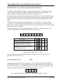
WORD ADDRESS PROGRAMMING LANGUAGE............................................................................... 1
WADR.1
WADR.1.1
AO-73290
WORD ADDRESS PROGRAMMING ........................................................................................1
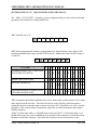
WORD ADDRESS DATA BLOCK SPECIFICATION ..............................................................1
Table of Contents-v
2.5RS OPERATION AND MAINTENANCE MANUAL
WADR.1.2
WADR.1.3
WADR.1.4
WADR.1.5
WADR.1.6
WADR.1.7
WADR.1.8
WADR.1.9
WADR.1.10
WADR.1.11
WADR.1.12
“N”-LINE NUMBER .................................................................................................................2
“P”-PROGRAM NUMBER .......................................................................................................2
X-DIMENSION FOR LINES OR ARCS ...................................................................................2
Y-DIMENSION ........................................................................................................................3
I-DIMENSION-FOR ARCS......................................................................................................4
J-DIMENSION-FOR ARCS .....................................................................................................5
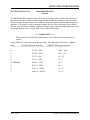
SPECIAL NOTE ON PROGRAMMING ARCS........................................................................5
G-PREPARATORY FUNCTION .............................................................................................6
“M”-MACHINE AUXILIARY FUNCTIONS ...............................................................................7
“M”- DWELL TIME ..................................................................................................................8
“F”-FEEDRATE .......................................................................................................................8
CODE DESCRIPTIONS ......................................................................................................................... 9
WADR.1.13
WADR.1.13.1
WADR.1.14
WADR.1.15
WADR.1.16
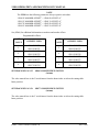
“G” CODE DESCRIPTIONS....................................................................................................9
OVERALL PROGRAM REPEAT ........................................................................................11
LOOP PROGRAMMING .......................................................................................................11
“M”-CODE DESCRIPTIONS .................................................................................................12
WORD ADDRESS SAMPLE PROGRAM .............................................................................15
ESSI PROGRAMMING ........................................................................................................................ 19
ESSI.2
ESSI.2.1
ESSI.2.2
ESSI.2.3
ESSI PROGRAMMING ...........................................................................................................19
LINE AND ARC BLOCK SPECIFICATIONS ...........................................................................19
ESSI AUXILIARY FUNCTIONS...............................................................................................22
ESSI SAMPLE PROGRAM .....................................................................................................25
PART 5 SERIAL COMMUNICATIONS........................................................................... 5
SERIAL COMMUNICATIONS................................................................................................................ 1
SERIAL.1
SERIAL.2
SERIAL.3
SERIAL.4
SERIAL.5
SERIAL.6
SERIAL.7
SERIAL.8
SERIAL.8.1
SERIAL.8.2
SERIAL.8.3
SERIAL.8.4
SERIAL.8.5
SERIAL.8.6
SERIAL.8.7
SERIAL.8.8
SERIAL.8.9
SERIAL.8.10
SERIAL.8.11
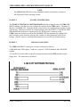
CONFIGURING THE COMMUNICATION PORT......................................................................4
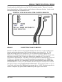
CONNECTING TO RS-232 DEVICES.......................................................................................7
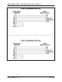
RS-232 PIN CONFIGURATION ................................................................................................8
RS-232 FOR HARDWARE HANDSHAKING.............................................................................9
RS-232 FOR SOFTWARE HANDSHAKING ...........................................................................11
CONNECTION TO RS-422 DEVICES.....................................................................................12
CHARACTER FORMATS........................................................................................................14
HANDSHAKING PROTOCOL SPECIFICATIONS ..................................................................15
RTS/CTS HARDWARE PROTOCOL....................................................................................15
XON/XOFF SOFTWARE PROTOCOOL (SPECIAL HANDSHAKING PROTOCOL) ...........16
COMMUNICATION ENHANCEMENT OPTION....................................................................16
LOAD-FROM RS232 USING RTS/CTS (HARDWARE HANDSHAKING)............................16
TYPICAL LOAD-FROM RS232 USING XON/XOFF (SOFTWARE HANDSHAKING) ..........18
CAD LINK (CLINK) PROTOCOL ..........................................................................................19
FILE DATA <ESC>!FD..........................................................................................................19
FILE GET <ESC>!FG............................................................................................................20
FILE QUEUE <ESC>!FQ ......................................................................................................21
FILE QUIT <ESC>!QQ .......................................................................................................22
THREE DIGIT STATUS CODES.........................................................................................23
PART 6 SERVICE........................................................................................................... 7
SERVICE ................................................................................................................................................ 1
SERVICE.1
INSTALLATION OF THE BURNY® 2.5RS .............................................................................1
SERVICE.1.1
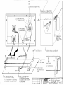
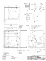
PHYSICAL INSTALLATION OF THE BURNY® 2.5RS ........................................................1
SERVICE.1.2
ELECTRICAL INSTALLATION OF THE BURNY® 2.5RS....................................................2
SERVICE.1.3
CHECKING THE INSTALLATION ........................................................................................3
SERVICE.1.4
FUNCTIONAL TESTING OF THE SYSTEM AFTER INSTALLATION ...............................4
INSTALLATION.2
LIST OF DIAGNOSTICS AND TESTS OF THE 2.5RS .................................................5
INSTALLATION.3 REPAIR OF THE BURNY 2.5RS .................................................................................6
SERVICE.3.1
FAULT FINDING AND TROUBLESHOOTING .....................................................................7
SERVICE.3.2
SPARE PARTS ....................................................................................................................8
SERVICE.4
SPECIAL TOOLS....................................................................................................................8
SERVICE.5
BACKUP OF PROGRAMS AND TABLES
STORED IN BURNY CONTROLS ..................8
SERVICE.6
REPLACING THE BURNY® 2.5RS MEMORY BATTERY .....................................................9
AO-73290
Table of Contents-vi
TABLE OF CONTENTS
SERVICE.7
BEFORE CALLING BURNY®...............................................................................................11
PART 7 SYSTEM SETUP AND CONFIGURATION ..................................................... 7
SYSTEM SETUP AND CONFIGURATION ........................................................................................... 1
SETUP&CONFIG.1
SETUP&CONFIG.2
SETUP&CONFIG.3
SETUP&CONFIG.4
SETUP&CONFIG.4.1
SERVICE MODE KEY .................................................................................................1
DISPLAY FUNCTIONS ................................................................................................1
POWER UP DIAGNOSTICS........................................................................................3
SERVICE AND DISPLAY MODES ..............................................................................4
SERVICE AND DISPLAY MODE MENUS ................................................................5
SERVICE MODES IN THE 2.5RS.............................................................................................................................. 5
SETUP&CONFIG.4.1.1 SERV00, DSPY00 - EXIT MODE...........................................................................5
SETUP&CONFIG.4.1.2 SERV01, DSPY01 - X/Y DISPLAY ........................................................................5
SETUP&CONFIG.4.1.3 SERV02, DSPY02 - PARTS CUT ..........................................................................6
SETUP&CONFIG.4.1.4 SERV03, DSPY03 - FEEDRATE ...........................................................................6
SETUP&CONFIG.4.1.5 SERV05 - SYS. STATUS.......................................................................................6
SETUP&CONFIG.4.1.6 SERV10, DSPY10 - SYS DATA.............................................................................6
SETUP&CONFIG.4.2 SYSTEM DATA PARAMETERS MENU: ..................................................................7
SETUP&CONFIG.4.2.1 SD01-ARC ON DELAY (seconds) ...................................................................10
SETUP&CONFIG.4.2.2 SD02-BLEEDOFF TIME (seconds)..................................................................10
SETUP&CONFIG.4.2.3 SD03-ACCEL TIME (seconds, multiple parameter) .........................................10
SETUP&CONFIG.4.2.4 SD04-MAXIMUM DRIVE SPEED (ipm/MPM) ..................................................10
SETUP&CONFIG.4.2.5 SD06-BACKUP SPEED (ipm/MPM) ................................................................11
SETUP&CONFIG.4.2.6 SD07-CORNER SPEED (ipm/MPM, multiple parameter) ................................11
SETUP&CONFIG.4.2.7 SD08-MINIMUM HOLD SPEED (ipm/MPM) ....................................................12
SETUP&CONFIG.4.2.8 SD09-ERROR SPEED MAXIMUM (ipm/MPM) ................................................13
SETUP&CONFIG.4.2.9 SD10-RUN SPD LIMIT (ipm/MPM, multiple parameter) ..................................13
SETUP&CONFIG.4.2.10 SD11-TRAVERSE SPEED LIMIT (ipm/MPM)................................................13
SETUP&CONFIG.4.2.11 SD12- MIN ACCEL (Seconds) .......................................................................13
SETUP&CONFIG.4.2.12 SD14-GAIN BREAK (encoder counts, multiple parameter)............................14
SETUP&CONFIG.4.2.13 SD15-ERROR WARNING DISTANCE (in/mm) .............................................14
SETUP&CONFIG.4.2.14 SD16-LOOP GAIN (multiple parameter) ........................................................15
SETUP&CONFIG.4.2.15 SD17-ARC OFF DELAY (seconds)................................................................16
SETUP&CONFIG.4.2.16 SD18-SLOWDOWN DISTANCE (in/mm, multiple parameter) .......................16
SETUP&CONFIG.4.2.17
SD19-HEIGHT SENSOR DISABLE LOOKAHEAD.........................................17
SETUP&CONFIG.4.2.18 SD20-X ENC DIST/REV ....................................................................................17
SETUP&CONFIG.4.2.19 SD21-Y ENC DIST/REV ....................................................................................17
SETUP&CONFIG.4.2.20 SD22-ENC COUNTS/REV.................................................................................17
SETUP&CONFIG.4.2.21 SD23-X ENCODER DIR ....................................................................................18
SETUP&CONFIG.4.2.22 SD24-Y ENCODER DIR ....................................................................................18
SETUP&CONFIG.4.2.23 SD25-X DRIVE DIR ...........................................................................................18
SETUP&CONFIG.4.2.24 SD26-Y DRIVE DIRECTION..............................................................................18
SETUP&CONFIG.4.2.25 SD27-PLATE SIDE ............................................................................................19
SETUP&CONFIG.4.2.26 SD28-HEIGHT RELAY (Norm/Rev) ...............................................................19
SETUP&CONFIG.4.2.27 SD29-SLOWDOWN RADIUS (in/mm, multiple parameter)............................20
SETUP&CONFIG.4.2.28 SD30-MIN RAD SPD (in/mm, multiple parameter).........................................20
SETUP&CONFIG.4.2.29 SD31-PLASMA TB1...........................................................................................20
SETUP&CONFIG.4.2.30 SD32-MIN SLW ANG (degrees, multiple parameter).....................................21
SETUP&CONFIG.4.2.31 SD33-MAX SLW ANG (degrees, multiple parameter)....................................21
SETUP&CONFIG.4.2.32 SD40-X MARKER OFFSET #1 (in/mm).........................................................22
SETUP&CONFIG.4.2.33 SD41-Y MARKER OFFSET #1 (in/mm).........................................................22
SETUP&CONFIG.4.2.34
SD42-MARKING SPEED (Not used in this control)
(ipm/MPM) ...........23
SETUP&CONFIG.4.2.35
SD43-MARKER DELAY (Not used in this control)
(seconds) ..................23
SETUP&CONFIG.4.2.36 SD45-DEFAULT DWELL (seconds, multiple parameter)...............................23
SETUP&CONFIG.4.2.37 SD46-MIN OFF DELAY (seconds, multiple parameter) .................................23
SETUP&CONFIG.4.2.38 SD47-X MARKER OFFSET #2 (in/mm).........................................................23
SETUP&CONFIG.4.2.39 SD48-Y MARKER OFFSET #2 (in/mm).........................................................23
SETUP&CONFIG.4.2.40 SD49-START DELAY (seconds, multiple parameter) ....................................24
SETUP&CONFIG.4.2.41 SD50-SERIAL DEFINITION...............................................................................24
PROGRAMMING LANGUAGE, SD50...................................................................................................................... 25
CHARACTER FORMAT SPECIFICATION, SD50 .................................................................................................... 26
SETUP&CONFIG.4.2.42
SD51-PRGM FORMAT ......................................................................................28
PROGRAM FORMAT, SD51.................................................................................................................................... 28
AO-73290
Table of Contents-vii
2.5RS OPERATION AND MAINTENANCE MANUAL
SETUP&CONFIG.4.2.43
SETUP&CONFIG.4.2.44
SETUP&CONFIG.4.2.45
SETUP&CONFIG.4.2.46
SETUP&CONFIG.4.2.47
SD52-SPECIAL EOP .........................................................................................34
SD53-FILE EXTEN ............................................................................................36
SD60-OPERATING SYS....................................................................................37
SD61-SYSTEM CONFIGURATION #1 ..........................................................37
SD62-SYSTEM CONFIGURATION #2 ..........................................................38
SD62-SYSTEM CONFIGURATION #2..................................................................................................................... 38
PROGRAM FORMAT SD62..................................................................................................................................... 42
SETUP&CONFIG.4.2.48
SD63-SYSTEM CONFIGURATION #3 ...........................................................46
SETUP&CONFIG.4.2.49 SD65..................................................................................................................46
SETUP&CONFIG.4.2.50 SD68-SPEED RANGE (in/mm)......................................................................47
SETUP&CONFIG.4.2.51 SD69-LANGUAGE SEL. ....................................................................................48
SETUP&CONFIG.4.2.52 SD70-KNIFE DIA. (in/mm) .............................................................................49
SETUP&CONFIG.4.2.53 SD71-KNIFE BP ANGLE (degrees) ...............................................................49
SETUP&CONFIG.4.2.54
SD80-SD95 PROGRAMMABLE OFFSETS (in/mm)...................................49
SETUP&CONFIG.4.2.55 SD96-X HOME INDEX SWITCH (in/mm).......................................................50
SETUP&CONFIG.4.2.56 SD97-Y HOME INDEX SWITCH (in/mm).......................................................50
SETUP&CONFIG.4.2.57 SDA0-X LASH (inches)..................................................................................51
SETUP&CONFIG.4.2.58 SDA1-Y LASH (inches)..................................................................................51
SETUP&CONFIG.4.2.59 SDA2-LASH RATE (inches)...........................................................................51
SETUP&CONFIG.4.3
MULTIPLE SETUP PARAMETER TABLES ........................................................51
SETUP&CONFIG.4.4 SYSTEM VARIABLE DISPLAY...............................................................................54
SETUP&CONFIG.4.4.1 V01-X DRIVE .......................................................................................................55
SETUP&CONFIG.4.4.2 V02- XDAOUT .....................................................................................................55
SETUP&CONFIG.4.4.3 V03-X ABS (in/mm)..........................................................................................55
SETUP&CONFIG.4.4.4 V04-X ENC ..........................................................................................................56
SETUP&CONFIG.4.4.5 V05-X ERROR (in/mm)....................................................................................56
SETUP&CONFIG.4.4.6 V06-XERSCL .......................................................................................................56
SETUP&CONFIG.4.4.7 V07-X HOME .......................................................................................................57
SETUP&CONFIG.4.4.8 V11-Y DRIVE .......................................................................................................57
SETUP&CONFIG.4.4.9 V12-YDAOUT ......................................................................................................57
SETUP&CONFIG.4.4.10 V13-Y ABS.........................................................................................................57
SETUP&CONFIG.4.4.11 V14-Y ENC ........................................................................................................57
SETUP&CONFIG.4.4.12 V15-Y ERROR ...................................................................................................57
SETUP&CONFIG.4.4.13 V16-YERSCL .....................................................................................................57
SETUP&CONFIG.4.4.14 V17-Y HOME .....................................................................................................57
SETUP&CONFIG.4.4.15 V20-RADERR (in/mm) ...................................................................................58
SETUP&CONFIG.4.4.16 V21-RADSCL.....................................................................................................58
SETUP&CONFIG.4.4.17 VARIABLES 22-49.............................................................................................58
SETUP&CONFIG.4.4.18 V50-BP INPUT...................................................................................................59
SETUP&CONFIG.4.4.19 V54-XCNTR .......................................................................................................59
SETUP&CONFIG.4.4.20 V55-YCNTR .......................................................................................................59
SETUP&CONFIG.4.4.21 V60-BP OUT ......................................................................................................59
SETUP&CONFIG.4.4.22 V72-X BACKLASH.............................................................................................60
SETUP&CONFIG.4.4.23 V73-Y BACKLASH.............................................................................................60
SETUP&CONFIG.4.5 MEMORY DISPLAY UTILITIES ..............................................................................60
SETUP&CONFIG.4.5.1
SERV30-SINGLE WORD MEMORY DISPLAY ...............................................61
SETUP&CONFIG.4.5.2
SERV31-DOUBLE WORD MEMORY DISPLAY...............................................62
SETUP&CONFIG.4.5.3 SERV32-16 BIT CRU DISPLAY...........................................................................62
SETUP&CONFIG.4.5.4
SERV33-SINGLE BYTE MEMORY DISPLAY ..................................................63
SETUP&CONFIG.4.5.5 SERV34-8 BIT CRU DISPLAY.............................................................................63
SETUP&CONFIG.4.5.6 SERV50-AXIS SPEED.........................................................................................63
SETUP&CONFIG.4.5.7SERV51-SPEED CALIBRATION..............................................................................64
SETUP&CONFIG.4.5.8 SERV52-MEMORY RESET .................................................................................65
SETUP&CONFIG.4.5.9
SERV 54-AUTOMATIC REFERENCE ADJUSTMENT.....................................66
SETUP&CONFIG.4.5.10 SERV70-CUSTOM AUX TABLES .....................................................................67
SETUP&CONFIG.4.5.11 SERV78-LOOP BACK .......................................................................................72
SETUP&CONFIG.4.5.12 SERV97-VARIABLE STORE .............................................................................73
SETUP&CONFIG.4.5.13 SERV98-SYS. RESET .......................................................................................74
TYPICAL SETUP EXAMPLE ................................................................................................................................... 74
SERV54- REF ADJUST FOR THE BURNY® 2.5 PLUS................................................................................................ 80
INTERFACE ........................................................................................................................................... 1
MACH.1
MACH.1.1
AO-73290
MACHINE INTERFACE.............................................................................................................1
SENSING INPUTS ....................................................................................................................1
Table of Contents-viii
TABLE OF CONTENTS
MACH.1.2
MACH.1.3
MACH.1.4
MACH.2
MACH.2.5
MACH.2.6
MACH.2.7
MACH.2.8
MACH.2.9
MACH.2.10
MACH.2.11
MACH.2.12
MACH.2.13
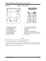
E-STOP SENSING INPUT ........................................................................................................2
OXY/FUEL CUT SENSE INPUT ...............................................................................................3
OXY/FUEL CUT INTERFACE DESCRIPTION..........................................................................3
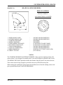
RELAY CONTACTS ..................................................................................................................4
OXY ENABLE CONTACT .........................................................................................................4
OXY START CONTACT............................................................................................................5
HI PREHEAT CONTACT...........................................................................................................5
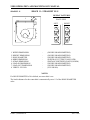
PLASMA INTERFACE...............................................................................................................6
PLASMA ARC ON “GO” INPUT ................................................................................................6
PLASMA ENABLE CONTACT ................................................................................................7
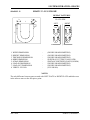
PLASMA START CONTACT ..................................................................................................8
PLASMA HEIGHT DISABLE CONTACT.................................................................................8
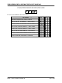
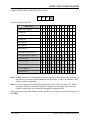
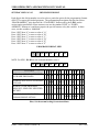
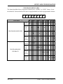
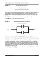
CUT CONTROL RELAY OUTPUT SEQUENCING DIAGRAMS...........................................9
MANUAL OXY/FUEL CUTTING SEQUENCE ............................................................................................................ 9
OXY/FUEL -“AUTOCUT” RELAY SEQUENCING .................................................................................................... 10
PLASMA CUTTING- “MANUAL CUT” RELAY SEQUENCING ................................................................................. 11
PLASMA CUTTING- “AUTOCUT” RELAY SEQUENCING ....................................................................................... 12
PART 8 ERROR MESSAGES ........................................................................................ 9
ERROR MESSAGES ............................................................................................................................. 1
ERROR.1
ERROR.1.1
ERROR.1.2
ERROR.1.3
ERROR.1.4
ERROR.1.5
ERROR.1.6
ERROR.1.7
ERROR.1.8
ERROR.1.9
ERROR.1.10
ERROR.1.11
ERROR.2
ERROR.2.1
ERROR.2.2
ERROR.3
ERROR.4
ERROR.4.1
ERROR.4.2
ERROR.4.3
ERROR.4.4
ERROR.4.5
ERROR.4.6
ERROR.4.7
ERROR.4.8
ERRORS FROM PROGRAM OPERATIONS............................................................................1
DUPLICATE PROGRAM ........................................................................................................1
PROGRAM LIST EMPTY........................................................................................................1
ENTER PROGRAM NUMBER................................................................................................1
NO PROGRAM FOUND .........................................................................................................2
MEMORY DISABLED .............................................................................................................2
PROGRAM MEMORY FULL...................................................................................................2
END OF LIST..........................................................................................................................2
“0” BYTES IN PROGRAM.......................................................................................................2
RECYCLE ERRORS...............................................................................................................3
DATA ERROR - RESET MEMORY ......................................................................................3
RESET MODE ONLY............................................................................................................3
RUN TIME ERRORS.................................................................................................................4
MEMORY TRIP WHILE RUNNING.........................................................................................4
PATH ERROR ........................................................................................................................4
TEACH MEMORY ERRORS.....................................................................................................4
ERRORS DURING SERIAL I/O OPERATIONS ........................................................................4
READ TIMEOUT.....................................................................................................................4
WRITE TIMEOUT ...................................................................................................................5
PARITY ERROR .....................................................................................................................5
OVERRUN ERROR ................................................................................................................5
FRAMING ERROR..................................................................................................................5
DATA COMM ERROR ............................................................................................................5
FORMAT ERROR ...................................................................................................................5
PROGRAM NUMBER WARNING...........................................................................................5
PART 9 RETROFITS ...................................................................................................... 9
RETROFIT AND RETROFIT INSTALLATION ...................................................................................... 1
RETRO.1
RETRO.2
RETRO.3
RETRO.4
GENERAL EXPLANATION OF A CNC RETROFIT ..................................................................1
GEAR RACK MOUNTING.........................................................................................................2
ENCODER MOUNTING EXPLANATION ..................................................................................3
CABLE LENGTH DETERMINATION.........................................................................................4
PART 10 PRODUCT SPECIFICATIONS...................................................................... 11
PRODUCT SPECIFICATIONS............................................................................................................... 1
SPECS.1
SPECS.2
PHYSICAL ENVIRONMENT OPERATING LIMITS...................................................................1
ELECTRICAL SPECIFICATIONS .............................................................................................1
PART 11 DRAWINGS & SCHEMATICS ...................................................................... 27
AO-73290
Table of Contents-ix
2.5RS OPERATION AND MAINTENANCE MANUAL
BLANK
AO-73290
Table of Contents-x
WARRANTY
WARRANTY AND LIMITATION OF LIABILITY
ALL EQUIPMENT IS SOLD SUBJECT TO THE MUTUAL AGREEMENT THAT IT IS
WARRANTED BY THE COMPANY TO BE FREE FROM DEFECTS OF MATERIAL AND
WORKMANSHIP BUT THE COMPANY SHALL NOT BE LIABLE FOR SPECIAL,
INDIRECT OR CONSEQUENTIAL DAMAGES OF ANY KIND UNDER THIS CONTRACT
OR OTHERWISE. THE COMPANY’S LIABILITY SHALL BE LIMITED EXCLUSIVELY
TO REPLACING OR REPAIRING WITHOUT CHARGE, AT ITS FACTORY OR
ELSEWHERE AT ITS DISCRETION, ANY MATERIAL OR WORKMANSHIP DEFECTS
WHICH BECOME APPARENT WITHIN ONE YEAR FROM THE DATE ON WHICH THE
EQUIPMENT WAS SHIPPED, AND THE COMPANY SHALL HAVE NO LIABILITY FOR
DAMAGES OF ANY KIND ARISING FROM THE INSTALLATION AND/OR USE OF THE
APPARATUS BY ANYONE. THE BUYER BY THE ACCEPTANCE OF THE EQUIPMENT
WILL ASSUME ALL LIABILITY FOR ANY DAMAGES WHICH MAY RESULT FROM
ITS USE OR MISUSE BY THE BUYER, HIS OR ITS EMPLOYEES, OR BY OTHERS.
THE WARRANTIES OF THE COMPANY DO NOT COVER, AND THE COMPANY
MAKES NO WARRANTY WITH RESPECT TO ANY DEFECT, FAILURE,
DEFICIENCY OR ERROR WHICH IS:
(A) NOT REPORTED TO THE COMPANY WITHIN THE APPLICABLE WARRANTY
PERIOD; OR
(B) DUE TO MISAPPLICATION, MODIFICATION, DISASSEMBLY, ABUSE,
IMPROPER INSTALLATION BY OTHERS, ABNORMAL CONDITIONS OF
TEMPERATURE, DIRT, OR CORROSIVE MATTER; OR
(C) DUE TO OPERATION, EITHER INTENTIONAL OR OTHERWISE, ABOVE RATED
CAPACITIES OR IN AN OTHERWISE IMPROPER MANNER.
THERE ARE NO OTHER WARRANTIES, EXPRESS
OR IMPLIED INCLUDING THE IMPLIED
WARRANTIES OF MERCHANTABILITYAND
FITNESS FOR A PARTICULAR PURPOSE
AO-73290
WARRANTY-xvii
2.5RS OPERATION AND MAINTENANCE MANUAL
BLANK
WARRANTY-xviii
AO-73290
PART 1 SYSTEM OVERVIEW
Tab Page - Part 1
BLANK
SYSTEM OVERVIEW: GENERAL OPERATION SUMMARY
SYSTEM OVERVIEW
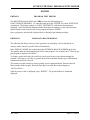
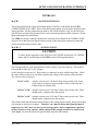
INTRODUCTION
The Burny 2.5 RS control with the new front panel and the Burny 2.5Plus control have identical
operating functions and physical layouts. The two versions of this control differ only in the
appearance of the front panel and in their processor card. The processor card in the Burny
2.5Plus operates at a much higher speed. This manual covers both versions of the control with
spare parts lists and drawings for both. Both front panels appear on Page PART1:OPSUMMARY-6.
The 2.5RS control is designed for use with optical tracing systems on a variety of 2 axis shape
cutting machines. With its extensive STANDARD SHAPE LIBRARY many parts can be cut
without the need for a template. In addition, the TEMPLATE TEACH UTILITY learns a part
outline by tracing the template one time. Then the part may be repeated any number of times
without re-tracing the template. When the 2.5RS control is added to a tracing system, the tracer
is not affected in any way and all other machine functions remain operational.
The optional RS-232/422 gives the control the ability to communicate with other devices such as
CAD Systems and other RS-232 or 422 compatible devices. The 2.5RS has the ability to prompt
the operator in a second language in addition to the standard English. Current languages
available are German, French, Finnish, Spanish, Swedish and Portuguese.
The 2.5RS control has a variety of STANDARD as well as many OPTIONAL FEATURES. This
manual covers all aspects of the operation, both STANDARD and OPTIONAL so certain parts
of this manual may not apply to all units.
NOTE
The 2.5RS has the ability to operate as a RS-422 device or a RS-232 device. This manual
refers to the control acting as a RS-232 device except where noted.
The system has extensive SERVICE/DIAGNOSTIC UTILITIES which allow many of the
operating values to be displayed and modified. In addition, all setup variables (acceleration
rates, speeds, gains, etc.) are stored in non-volatile memory devices which retain the values
permanently, even in the event of simultaneous battery and power failure. Note that the Custom
Auxiliary Code tables, and user programs, are not saved in non-volatile devices, but are
preserved by the battery backup system.
Several places throughout this manual will refer to a value which is entered during
“INSTALLATION & SETUP”. In these cases, consult the INSTALLATION section of this
manual for further details. This manual describes SETUP, INSTALLATION and NORMAL
procedures required for day to day operation. The 2.5RS control can operate using either an
“inch” or “metric” operating system.
AO-73290
PART 1; OPSUMMARY-1
2.5RS OPERATION AND MAINTENANCE MANUAL
This selection is made during the SETUP and INSTALLATION. All prompts and system
variables will switch to the selected system and appear as either “INCH” or “MILLIMETER”
values. When entering values for STANDARD SHAPES, the part dimensions may be entered in
either INCHES or MILLIMETERS regardless of the operating system selection. This allows a
user who normally operates in inch values to input a metric part directly without needing to
convert first. This manual is used with both inch and metric systems, therefore, dimensions will
generally not be described as inches or millimeters but are assumed to be in the unit selected by
the system.
PART 1; OPSUMMARY-2
AO-73290
SYSTEM OVERVIEW: GENERAL OPERATION SUMMARY
2.5RS GENERAL OPERATION SUMMARY
OPSUMMARY.1
NC/TRACER SWITCHING
There is no power on/off switch on the 2.5RS CONTROL, it is ON any time the CUTTING
MACHINE HAS POWER. To use the normal TRACING/CUTTING functions of the machine
without the 2.5RS CONTROL, press the “NC RUN” button to turn off the LED located in the
corner of the button. This causes the 2.5RS CONTROL to return all control of the cutting and
drive/tracer functions to the manual controls and allows normal tracer operation. Pressing the
“NC RUN” button again will cause the LED to light and return control of the drives and cutting
functions to the 2.5RS CONTROL.
OPSUMMARY.2
OPTIONAL LANGUAGE FEATURE
The 2.5RS control has an alternate language that is available as a option. The 2.5RS normally
prompts the operator in the English language. However, there are several other optional
languages which can be installed in the unit (French, German, Finnish, Swedish, Spanish and
Portuguese). When the alternate language feature is enabled, the control switches to the new
language automatically at power-up. However, for service personnel, and in cases where the
translation is not clear, the prompts may be switched back to ENGLISH. On older front panels,
this may be done by pressing the “DOT” key which is directly above the RECYCLE key on the
panel. On newer front panels the “SHF” and “DSPY” keys should be pressed within two seconds
of each other. Pressing these keys toggles the display between English and the alternate
language.
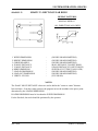
OPSUMMARY.3
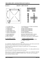
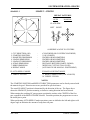
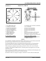
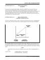
AXIS DEFINITIONS
Several places in this manual refer to the X and Y axis of the machine. These are defined as:
X AXIS
-The main longitudinal rail axis of the machine. The direction away from
the operator is defined as +X and toward the operator is defined as -X.
Y AXIS
-The cross or traverse axis of the machine. The direction to the left is
defined as +Y and to the right as -Y.
AO-73290
PART 1; OPSUMMARY-3
2.5RS OPERATION AND MAINTENANCE MANUAL
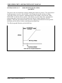
OPSUMMARY.4
CUTTING SPEED CONTROL
The cutting speed is controlled by the operator using the speed dial and the “HI-LO-OFF”
selector switch or by the NC programmer with the insertion of feedrate commands in the actual
part program. The traverse speed used to get from one cut to the next is preset during
installation. This allows the speed dial to be set at a slow speed for the cutting process and still
move at a high speed to get from one part to the next.
The PROGRAMMABLE FEEDRATE option allows the feedrate to be controlled from the part
program. The feedrate option must be enabled and the correct bit set in “SD62-SYS CONFG2”.
See the section “SETUP AND CONFIGURATION”for programmable feedrate information.
Once a program contains a programmed feedrate code, the control is automatically switched to
the digital feedrate mode where the normal speed pot is now a 0-100% override control on the
programmed feedrate. Pressing the feedrate button, or selecting DSPY03 displays the current
digital feedrate (scaled by the 0-100% override pot) and allows the programmed value to be
altered by either scrolling or entering the new feedrate on the keypad.
NOTE:
On older controls, the feedrate key is the white dot that is located between the “SHF” key and the
down SCROLL arrow.
OPSUMMARY.5
JOG CONTROLS
In order to help in positioning the machine, the 2.5RS provides a front panel jog function. The
instructions below explain jog for the older style front panel as well as for the new style front
panel. The figure on the following pages is for the new front panel.
PART 1; OPSUMMARY-4
AO-73290
SYSTEM OVERVIEW: GENERAL OPERATION SUMMARY
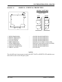
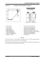
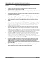
OPSUMMARY.5.1 JOG CONTROLS - OLD STYLE FRONT PANEL
The jog operation is initiated by pressing the “II” key on the left side of the panel. When this
key is pressed, the readout temporarily changes to the “SELECT JOG” prompt, and then returns
to the previous display. To activate the jog function, a sequence of two keys must be entered.
First, press the “II” key, then immediately press and hold the numeric key (1-9) that has an arrow
which indicates the correct jog direction. The machine will jog in the selected direction at the
cutting speed, as long as the number key is held, and will decel to a stop when it is released. To
jog again, first press the “II” key to re-activate the jog function, then press and hold the new jog
direction numeric key.
NOTE
The two key sequences described here and throughout the manual require that the second key
be pressed within 2 seconds of the first. Otherwise, the double key sequence will not be done
and only the second key will be read.
There is also a latched jog function which allows the machine to continue to move in the selected
direction without any keys being pressed. It is selected using a similar sequence. First press the
“II” key to activate the jog function, then press the “5” key to indicate that a latched jog is to be
performed. Finally, press the numeric key to indicate the desired jog direction. Each key must
be pressed within 2 seconds of the previous one or the sequence is interrupted. The machine
begins moving in the selected direction at the speed set on the speed dial. To stop the motion,
press the “0” key. (“CYCLE STOP” or “RECYCLE” may also be used to stop the latched jog
operation.)
NOTE
The “Latched Jog” feature may be disabled with SD62-SYS CONFG2. See Installation
documentation on SD62-SYS CONFG2.
OPSUMMARY.5.2 JOG AT MAXIMUM SPEED - OLD STYLE FRONT PANEL
A high speed jog may be initiated by a three key sequence. First press the “II” key, then press
the “SHF” before the jog direction is selected. Upon pressing the number key the machine will
move at the maximum traverse speed regardless of the feedrate setting, unless the feedrate is set
to 0.00, which causes the machine to stop. Pressing the “SHF” also causes the SCROLL led to
flash indicating high speed jog mode. Pressing “SHF” again returns to the normal jog mode.
The Max Speed Jog function only works with momentary jogs where the operator must keep the
button pressed. It will not work with the latched jog.
AO-73290
PART 1; OPSUMMARY-5
2.5RS OPERATION AND MAINTENANCE MANUAL
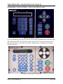
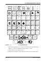
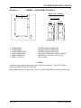
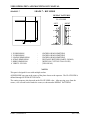
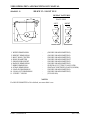
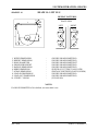
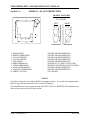
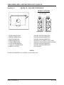
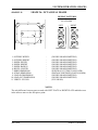
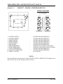
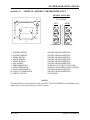
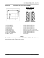
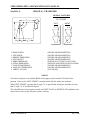
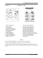
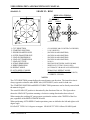
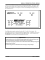
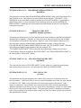
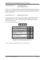
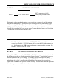
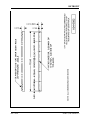
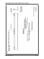
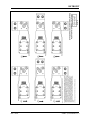
OPSUMMARY.5.3 JOG CONTROLS - NEW STYLE FRONT PANEL
NEW STYLE FRONT PANEL
Jog is accomplished by pressing one of the keys in the upper right hand corner of the front panel.
The machine jogs in the selected direction, at the cutting speed, as long as the direction key is
held, and will decel to a stop when it is released. Diagonal jog is accomplished by using the
latched jog function.
FRONT PANEL FOR 2.5 PLUS
PART 1; OPSUMMARY-6
AO-73290
SYSTEM OVERVIEW: GENERAL OPERATION SUMMARY
The latched jog function allows the machine to continue to move in the selected direction
without any keys being pressed. For latched jog, use the direction keys in the upper right hand
corner of the front panel. First press the “LATCH JOG” then press the direction key to indicate
the desired jog direction. Each key must be pressed within 2 seconds of the previous one or the
sequence is interrupted. The machine begins moving in the selected direction at the speed set.
To stop the motion, press “CYCLE STOP” or “RECYCLE”.
NOTE
The “Latched Jog” feature may be disabled with SD62-SYS CONFG2. See Installation
documentation on SD62-SYS CONFG2.
OPSUMMARY.5.4 JOG AT MAXIMUM SPEED - NEW STYLE FRONT PANEL
A high speed jog may be initiated by a two key sequence. First press the “SHF”, then press the
direction key. The SCROLL led will flash indicating high speed jog mode. The machine will
move at the maximum traverse speed regardless of the feedrate setting, unless the feedrate is set
to 0.00, which causes the machine to stop. Pressing “SHF” again returns to the normal jog
mode.
The Max Speed Jog function only works with momentary jogs. Latch Jog cannot be used with
Max Speed Jog.
OPSUMMARY.6
KEYBOARD OPERATIONS
Throughout this manual the operator is instructed to enter numbers and values for the various
selections. This is done using the 0-9 numeric keypad along with the “+/-“ and “.”
(DECIMAL POINT) keys when required. If an incorrect value is entered, the clear entry key
“CLR” or “CE” can be used to clear the value and allow it to be RE-ENTERED. Once the
correct value is displayed, press the “ENTER” key to continue. If a negative value is required,
first enter the number and then press the “+/-“ key to make it negative.
AO-73290
PART 1; OPSUMMARY-7
2.5RS OPERATION AND MAINTENANCE MANUAL
OPSUMMARY.7
SCROLLING OPERATIONS
The 2.5RS uses a menu system to guide the operator through the various operations. In this way,
the operation is broken into a series of simple steps with a limited number of choices at each
step. Usually when a menu of choices is available, the operator is told to SELECT the desired
function and press the “ENTER” key. This selection is done by using the up and down arrow
keys (located to the right of the keypad) to scroll through the displayed menu. When the correct
selection is displayed, press the “ENTER” key to continue.
The “LED” indicator located below the scroll arrow keys lights when a menu of choices is
available, and shows that the scroll arrow keys can be used to make the selection.
Some of the menus use numbers to further identify each item. If this is the case, the desired
number may be entered rather than scrolling to get directly to the correct selection.
OPSUMMARY.8
RECYCLE KEY
After an operation is complete, or at any time during any operation, pressing the “RECYCLE”
key stops the current operation, turns off all cutting functions and returns to the beginning
prompting sequence.
OPSUMMARY.9
DISPLAY KEY
The “DSPY” key may be used at any time to enter the display select menu function described in
the chapter “DISPLAY MODES”. Pressing this key does not affect the operation of the machine
in any way and so may be used at any time, even while a part is being cut. Once pressed, the
current display is removed and the display select menu is presented. Select the desired display
(see SCROLLING OPERATIONS). To exit the display mode and resume normal operation,
SELECT display “DSPY00-EXIT MODE”. When this is entered, the control returns to the
operation that was active before the display function was used.
PART 1; OPSUMMARY-8
AO-73290
SYSTEM OVERVIEW: GENERAL OPERATION SUMMARY
OPSUMMARY.10
PART RETURN KEY
The “PART RET.” key is used to return to one of 3 starting positions on a part in cases where the
cut was lost or must be repeated over a portion of the part. Pressing the “PART RET.” key the
first time returns to the most recent pierce point on the part. Pressing the “PART RET.” key a
second time returns to the start point of the current part. Pressing the “PART RET.” button a
third time will return to the home position on the selected cutting table.
Pressing “SHF” “PART RET.” returns to the table #1 0,0 home reference position.
OPSUMMARY.11
BACKUP KEY
The “BACKUP” key is also used to re-start lost cuts. When pressed, it stops the cutting process
and retraces the cut path in reverse. Once the correct point is reached, releasing the key cause
the program to continue forward from that point.
AO-73290
PART 1; OPSUMMARY-9
2.5RS OPERATION AND MAINTENANCE MANUAL
BLANK
PART 1; OPSUMMARY-10
AO-73290
PART 2 SYSTEM OPERATIONS
Tab Page - Part 2
BLANK
SYSTEM OPERATION: SHAPES
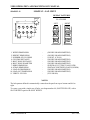
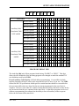
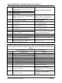
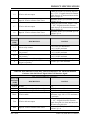
MAIN FUNCTION SELECTION MENU
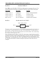
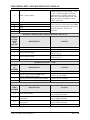
The FUNCTION SELECTION MENU is the starting point for all machine operations. At any
time, during any operation, pressing the “RECYCLE” key aborts the current operation and
returns to this top level of prompting.
When the “RECYCLE” key is pressed, the display sequences through:
“SELECT—FUNCTION”
“RUN- PROGRAM” ( or last function selected)
“USE SCROLL—“
“—TO SELECT”
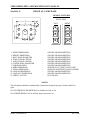
The “RUN PROGRAM” function is the default when power is applied to the 2.5RS. The default
function then becomes the last function used. The other functions are selected with
UP and DOWN scroll arrows or by pressing the appropriate number associated with that
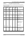
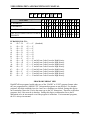
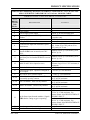
function. The selections are as follow:
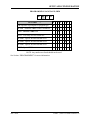
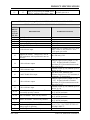
KEY
FUNCTION
DESCRIPTION
1
RUN- PROGRAM
Run the current program.
2
LOAD- STD. SHAPE
Load from STANDARD SHAPE
LIBRARY.
Option must be enabled.
3
LOAD- FROM RS-232
Load from a RS-232 device.
4
STORE- TO RS-232
Store to a RS-232 device.
5
TEACH- PROGRAM
Teach a program using a optical tracer.
6
DELETE- PROGRAM
Delete a program from program memory.
7
EDIT / NEW-PROGRAM
Create or edit a program.
.
STORE TO FLOPPY
Store to Floppy drive.
Option must be enabled.
LOAD FROM FLOPPY
Load from Floppy drive.
Option must be enabled.
3 SHF
TWO KEY
SEQUENCE
LOAD/RUN RS-232
Load from a RS-232 device and run
immediately.
+/- SHF
TWO KEY
SEQUENCE
LOAD FROM FLOPPY
Load from Floppy drive and immediately
Run. Floppy option must be enabled
+/-
AO-73290
PART 2; FUNCTION MENU-1
2.5RS OPERATION AND MAINTENANCE MANUAL
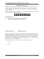
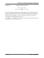
FUNCMENU.1
RUN PROGRAM
Once this function is selected, the prompt “PRGM=00000000” is displayed. At this point a
different program number may be entered via the numeric keypad. The scroll keys may also be
used to select a part in program memory. Press “ENTER” to select the program number.
The 2.5RS searches program memory for a part that has been assigned that number. If the part
program exists, the run prompting begins. See section “RUNNING THE PROGRAM”. If the
part program is not found, a “PGM NOT FOUND” error is displayed and program selection must
be repeated.
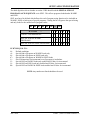
FUNCMENU.2
LOAD-FROM STD SHAPE
Once this function is selected, the prompt “PRGM=00000000” is displayed. A program number
is assigned to the selected GENERIC SHAPE to create a PART PROGRAM. A
PART PROGRAM is a runnable program that resides in program memory. Enter a program
number to be assigned to the GENERIC STANDARD SHAPE, (up to 8 digits) and then press
“ENTER”. The operator should select the desired shape from the following menu and go to the
manual section indicated for that shape. The selection of a shape can be made either by scrolling
to the desired shape or by entering the shape number on the keypad. Once the shape has been
selected and the data entered, the shape is assigned the 8 digit program number for future
reference.
The standard shape library contains 53 generic shapes. See the section “Standard Shapes.”
FUNCMENU.3
LOAD-FROM RS-232
The “LOAD FROM RS-232” function is used to download a part program via the serial port into
the 2.5RS memory. Once the function is selected, the prompt “PRGM=00000000” is displayed.
Enter the program number to be used to store the part program data and press “ENTER”. If the
PROGRAM NUMBER selected does not exist, the operator is prompted for additional
information pertaining to serial communication parameters. See section
SERIAL COMMUNICATIONS for further information on LOADING FROM RS-232.
If the program number requested already exists in program memory, then a special prompt
appears:
FUNCMENU.4
“DUP PGM=########”
If a duplicate program error is given, either enter a different number or go back and “DELETE”
the existing program, then return to the “LOAD” operation.
PART 2; FUNCTION MENU-2
AO-73290
SYSTEM OPERATION: SHAPES
FUNCMENU.5
LOAD CUSTOM SHAPE FROM FROM RS-232
Custom Shape Programs must be created by CMC, they are not customer programmable.
Custom Shape Programs are loaded using the same Serial loading method as normal Word
address or ESSI programs. However, Program must be set to INTL for internal format type
programs (this replaces the normal WADR or ESSI program format selection).
Custom Shape Programs have numeric file names (for example-- 9892.CNC). However, once
the program loads, it will appear as “BDF09892” in program memory to mark it as a special
Binary Data Format Custom Shape program instead of a regular part program.
To use the custom shape, you must first “RUN” the program. Select RUN and scroll down to the
program number “BDF09892” and press enter. The Running process will detect that it is one of
the new custom shape programs and will set it up to be used. The display will change to
“GENERIC XFER OK” which indicates the file has transferred to the standard shape memory
correctly.
The display then changes to the normal prompt to “LOAD xxxxxxxx”. This is the normal
prompt for loading a program into memory. Enter the program number that you want to create
and press enter. For example: “LOAD - 00000123”
The display then goes to the Shape Selection screen, and the custom shape number will appear as
the first shape. For example “SH9892-WELD”. You can press Enter to select this shape, or you
can use the scroll buttons or numeric keys to go through the list of standard and custom shapes.
There can be more than one custom shape loaded at one time. For example, if you scroll down,
the display will show Shapes 1 to Shape 53 and then go to SH9892. The custom shapes just
appear as another standard shape at this point.
Enter the dimensions for the custom shape as usual, and then run the resulting part program as
usual: RUN-00000123.
The normal “LOAD-FROM STD SHAPE” prompt will not access any Custom Shapes. If you
run the Standard Shapes the usual way, the Custom shape will not appear in the list—you must
go through the step of Running the BDF09892 program to get the GENERIC XFER OK message
to make the Custom Shape active.
FUNCMENU.6
STORE-FROM RS-232
The “STORE FROM RS-232” function is used to upload a part from program memory out the
serial port to a host storage device. Once the function is selected, the prompt
“PRGM=00000000” appears. Enter the program number to be STORED to the remote device.
AO-73290
PART 2; FUNCTION MENU-3
2.5RS OPERATION AND MAINTENANCE MANUAL
FUNCMENU.7
TEACH-PROGRAM
The “TEACH” function is used along with the machines optical tracing system to
“REMEMBER” an existing template and then repeat it any number of times without the
template. See “TEMPLATE TEACH TRACE” section of this manual for detailed description.
FUNCMENU.8
DELETE-PROGRAM
DELETE is used to erase a part program. Once the function is selected the prompt
“PRGM=00000000” appears. At this point enter the number for the program to be deleted. The
scroll keys may also be used to select a part in program memory for deletion. Press “ENTER” to
DELETE the program.
All programs in program memory can be deleted by entering the program number “00000000” in
response to the “PRGM= XXXXXXXX” prompt. When the “ENTER” key is pressed, a
verification prompt is issued to make sure the operator is aware that all programs will be erased:
“YES ERASE ALL NO”
Pressing the “+/-“ key toggles between a flashing “YES” and “NO”. To abort the function, press
the “+/-“ key so that the word “NO” is flashing and then press “ENTER”. The control aborts the
erase procedure and no programs are lost. To erase all the programs, press the “+/-“ key so the
word “YES” in the readout is flashing. Then press “ENTER”. Again, since this procedure is
irreversible, a second verification is given as:
“NO YOU SURE YES”
Notice that to erase all the programs, the “+/-“ key must be pressed twice again. This minimizes
the chances of an accidental erasure. Pressing the “ENTER” key with the “NO” flashing aborts
the process. If the “YES” response is selected, the programs are erased and the readout displays:
“PROGRAMS DELETED”
FUNCMENU.9
EDIT/NEW-PROGRAM
The EDIT/NEW function allows the EDIT of a part program that resides in program memory. It
may be altered in any way. The EDIT/NEW function also allows for the creation of a new part.
For a detailed description of the “EDIT/NEW- PROGRAM” function see section “EDITOR”.
PART 2; FUNCTION MENU-4
AO-73290
SYSTEM OPERATION: SHAPES
FUNCMENU.10
STORE-TO FLOPPY
The “STORE- TO FLOPPY” selection is used to save a part program to a floppy disk. If the
control has an internally mounted disk drive, the program is stored there. If the control does not
have an internal disk drive, and an external portable floppy drive is connected to the serial port,
the selected program is saved to the external floppy drive. See FLOPPY DRIVE in utilities
section for additional information on operation.
FUNCMENU.11
LOAD FROM FLOPPY
The “LOAD FROM FLOPPY” selection is used to load part programs from a floppy disk. If the
control has an internally mounted disk drive, the program is loaded from there. If the control
does not have an internal disk drive, and an external portable floppy drive is connected to the
serial port, the selected program is loaded from the external floppy drive. See FLOPPY DRIVE
in utilities section for additional operation.
FUNCMENU.12
LOAD/RUN RS-232
Use “LOAD/RUN RS-232” to load a part program from the serial port, and immediately run that
program. The 2.5RS can also automatically delete the program after cutting, and load the next
program. See “LOAD FROM RS-232” above.
FUNCMENU.13
LOAD/RUN FROM FLOPPY
Use “LOAD/RUN FLOPPY” to load a part program from a floppy and immediately run that
program. The 2.5RS can also automatically delete the program after cutting, and load the next
program. See “LOAD FROM FLOPPY” above
AO-73290
PART 2; FUNCTION MENU-5
2.5RS OPERATION AND MAINTENANCE MANUAL
BLANK
PART 2; FUNCTION MENU-6
AO-73290
SYSTEM OPERATION: SHAPES
STANDARD SHAPE SELECTION
SHAPE.1
SHAPE SELECTION
The “LOAD- FROM STD. SHAPE” function allows the operator of the 2.5RS to select a generic
part from the STANDARD SHAPE LIBRARY and create a part program.
Press the “ENTER” key. The display changes to “LOAD- 00000000”. This is the PART
PROGRAM NUMBER that will be assigned to the selected GENERIC SHAPE when the part
dimensions are entered. Once a program number is entered the shape selection process begins.
The 2.5RS shape library contains 50 SHAPE PROGRAMS which are referenced by
“SHAPE NUMBER”. The operator must first select the desired shape from the following chart
either using the scroll keys or by entering the desired number directly. Once the correct number
and name are displayed, press the “ENTER” key to select the shape.
Detailed drawings of each shape are located at the end of this section. These give additional
information about the various options for each shape and illustrate the required dimension inputs.
The STANDARD SHAPE programs are written in a “GENERIC” format which describes the
shape of the part but leaves the part dimensions variable. Once the shape has been selected, the
operator is required to answer a series of prompts which determines the final dimensions of the
part. The individual shape drawings at the end of this section help to illustrate the various
dimensions. These drawings should be referred to when answering the various prompts.
If a dimension is requested, use the numeric keypad along with the decimal point and “CE” or
“CLR” keys to enter the desired value. Once it is correct, press “ENTER”. Since the 2.5RS can
operate in either a metric or inch system, the standard units for the dimensions are those selected
for the operating system during installation by “SD60”. However, dimensions can be entered in
either unit by using a special key sequence. In this way, an occasional metric part can be entered
directly even though the system is set for inch units.
To enter a dimension in the opposite unit from the system default, press the “SHIFT” key first.
The displayed value is converted to the opposite unit (inch/mm) and the number of decimal
places will change (2 for inch, 1 for mm). Pressing the same key again changes the value back to
the original units. This key only changes the value being entered and does not switch the units
for the entire system. Each dimension must be converted individually as required.
If a count (such as number of holes) or other integer value is requested, use the numeric keypad
and clear key to enter the desired number. Once the value is correct, press “ENTER”.
AO-73290
PARTS 2; SHAPES-1
2.5RS OPERATION AND MAINTENANCE MANUAL
If a selection such as CW/CCW, YES/NO etc. is requested the displayed response may be
toggled by using the “+/-“ key. Press “ENTER” when the correct response is displayed. If a
start point or repeat direction is requested, use the outside row of keys on the numeric keypad 1-9
to indicate the correct corner or direction. Once the correct direction is indicated on the readout,
press ENTER. Invalid entries for a particular prompt are ignored.
Start point or repeat direction:
Once all the prompts are answered, a verification prompt appears, “YES+ VERIFY +NO”. To
verify the input data, which starts the prompting over again, press the “+/-“ key one time causing
the “YES+” to begin flashing. Then press the “ENTER” key to review the input data. Use the
“ENTER” key to step through the prompts, and correct any values as needed.
After all prompts have been answered correctly, the 2.5RS creates the part program. The
following prompts are displayed:
“* COMPUTING *” The input data is being processed.
“PROGRAM LOADED “ The program has been created.
Press RECYCLE to return the MAIN FUNCTION MENU. Go to “RUNNING THE PART” in
this manual for directions on actually running the program.
PART 2; SHAPES-2
AO-73290
SYSTEM OPERATION: SHAPES
SHAPES.2
DIMENSIONS COMMON TO MOST SHAPES
In addition to the actual dimensions of the part, most of the 53 SHAPE PROGRAMS also
prompt for the following:
KERF
SCRAP
LEADIN
LEADOUT
The standard shapes also prompt for a “KERF” value along with the part dimensions. Since all
controls are now equipped with the optional “Dial-in-Kerf” feature (described in the RUN
PROGRAM section of this manual), the value of 0.00 should be entered for the KERF prompt
during the dimension entry (See exceptions below). By entering 0.00 at this point, the
“Dial-in-Kerf” feature can be used when the part is actually cut to enter and adjust the kerf
dimension as needed. If a KERF value other than 0.00 is entered during the dimension
prompting of a standard shape, it is permanently added to the part dimensions, and the
“Dial-in-Kerf” feature is bypassed when the part is cut thus the kerf cannot be
adjusted and the entire part must be re-entered to change it.
NOTE
On any “Chain Cut” parts, such as the WEDGE PAIR or CHAIN RECTANGLE, the kerf
must be entered along with the part dimensions during the program creation. This is due to
the common side cutting and nesting which is done on these parts. Regardless of the kerf
entered, the “DIAL-IN-KERF” will not function on these parts.
See also the “Dial In Kerf” section of this manual.
Most of the standard shapes also prompt for a “SCRAP” dimension (see below). This is the
space left between successive rows of parts. Since the “Dial-in-Kerf” feature does not increase
the part-to-part spacing, the value for “SCRAP” must allow for enough material to accommodate
the anticipated KERF plus the desired amount of actual material to be left between the rows of
parts.
AO-73290
PARTS 2; SHAPES-3
2.5RS OPERATION AND MAINTENANCE MANUAL
The “SCRAP” value provides the spacing between parts as they are repeated down the plate.
The accuracy of this scrap dimension is just as good as the actual part itself, therefore the value
can be set fairly small with good results. Typical “SCRAP” value for OXY/FUEL CUTTING
can be anywhere between .1” to .5” (2.5 mm to 12 mm). Note that the “SCRAP” dimension
must allow for the anticipated cutting kerf if the “Dial-in-Kerf” feature is to be used when the
part is cut (see KERF description above).
The “LEADIN” dimension is the distance from the part to the pierce point. Since the piercing
operation is sometimes unpredictable, the leadin dimension should be set so that the plate is
pierced and the cut has stabilized before it reaches the actual part. Normal values range from
.25” to 1.00” (6mm TO 25mm).
The “LEADOUT” dimension is programmable for each of the standard shapes, and causes the
torch to cut away from the part before the cutting oxygen is turned off. This prevents any
damage to the cut part due to the bleed off characteristics of the torch. In addition, on heavy
plate cutting, the leadout move guarantees that the bottom of the part has been cut completely
before the oxygen is turned off. Normal values are from .5” to 1” (12mm to 25mm).
For plasma systems, the “LEADOUT” should be adjusted to properly time the turn-off of the arc.
If the leadout is too long, cut parts will fall out of the plate and cause an abrupt turn off of the
torch. This will cause attempts to restart the plasma, and thus excessive wear on torch parts.
PART 2; SHAPES-4
AO-73290
SYSTEM OPERATION: SHAPES
1
*
2
*
3
*
4
5
6
7
8**
9
10
11
*
*
*
12
13***
14
*
*
*
15
16
17
18
19
20
21
22***
23***
24***
25***
26***
27***
28***
29***
30
31
32
33
34
35
36
37
38
39
40
41
42
43**
44**
45***
49
*
*
*
SHAPES.3 53
46***
47
48
50***
STANDARD SHAPES
* Selectable start position, cw/ccw cutting, and selectable repeat mode and direction.
Shapes 51, 52, and 53 are enhanced versions of shapes 1, 2, and 3.
** Allows selection of any number of holes.
*** Dashed holes are optional. Corner radius values may be set to 0 for sharp corners.
AO-73290
PARTS 2; SHAPES-5
2.5RS OPERATION AND MAINTENANCE MANUAL
SHAPE 1 : RECTANGLE
SHAPES3.1
REPEAT PATTERNS
4
AUTO
1
MANUAL
3
2
7
6
5
1. CUT DIRECTION
2. STARTING POSITION
3. X DIMENSION
4. Y DIMENSION
5. LEADIN DIMENSION
6. LEADIN ANGLE (DEGS)
7. LEADOUT DIMENSION
8. SCRAP DIMENSION
9. KERF DIMENSION
10. REPEAT MODE
IF AUTO REPEAT MODE:
11. VERIFY- YES/NO
:
:
:
:
:
:
:
:
:
:
(CLOCKWISE OR COUNTERCLOCKWISE)
(1 OF 4 CORNERS)
(INCHES OR MILLIMETERS)
(INCHES OR MILLIMETERS)
(INCHES OR MILLIMETERS)
(0 TO 90 DEGREES)
(INCHES OR MILLIMETERS)
(DISTANCE BETWEEN PARTS, IN/MM)
(WIDTH OF CUTTING TOOL PATH)
(AUTOMATIC OR MANUAL POSITIONING)
IF MANUAL REPEAT MODE:
11. REPEAT DIRECTION: (1 OF 4 SIDES)
12. VERIFY- YES/NO
NOTES:
The STARTING CORNER and REPEAT DIRECTION parameters can be directly entered with
the numeric keypad. Direction arrows are provided for quick reference.
When defining the LEADIN ANGLE, 0 degrees is parallel to the Y axis and 90 degrees is
parallel to the X axis.
The LEADOUT position is determined by the direction of the cut. It is either parallel to the last
side cut (as shown) or 45 degrees from the last cut direction.
When running the resulting NC part program, position the torches at the STARTING CORNER
of the first part, regardless of the REPEAT MODE selected. From this corner, the program
moves out to the actual pierce point.
PART 2; SHAPES-6
AO-73290
SYSTEM OPERATION: SHAPES
SHAPE 2 : CIRCLE
SHAPES3.2
REPEAT PATTERNS
1
AUTO
MANUAL
PLATE SIDE
LEFT RIGHT
2
3
5
4
60 DEGREE ANGLE TO CENTERS
1. CUT DIRECTION (OD)
2. STARTING POSITION
3. DIAMETER DIMENSION
4. LEADIN DIMENSION
5. LEADOUT DIMENSION
6. SCRAP DIMENSION
7. KERF DIMENSION
8. REPEAT MODE
IF AUTO REPEAT MODE:
9. VERIFY- YES/NO
:
:
:
:
:
:
:
:
(CLOCKWISE OR COUNTERCLOCKWISE)
(1 OF 8 POINTS)
(INCHES OR MILLIMETERS)
(INCHES OR MILLIMETERS)
(INCHES OR MILLIMETERS)
(DISTANCE BETWEEN PARTS, IN/MM)
(WIDTH OF CUTTING TOOL PATH)
(AUTOMATIC OR MANUAL POSITIONING)
IF MANUAL REPEAT MODE:
9. REPEAT DIRECTION: (1 OF 4 POINTS)
10. VERIFY- YES/NO
NOTES:
The STARTING POSITION and REPEAT DIRECTION parameters can be directly entered with
the numeric keypad. Direction arrows are provided for quick reference.
The actual LEADOUT position is determined by the direction of the cut. The figure above
shows the LEADOUT position assuming a clockwise cutting direction has been selected.
When running the resulting NC part program, position the torches at the CENTER of the first
part, regardless of the REPEAT MODE selected. From this position, the program moves out to
the actual pierce point.
When performing AUTO REPEAT mode operations, parts are shifted to the left and right at a 60
degree angle to minimize the amount of scrap between parts.
AO-73290
PARTS 2; SHAPES-7
2.5RS OPERATION AND MAINTENANCE MANUAL
SHAPE 3 : RING
SHAPES3.3
REPEAT PATTERNS
3
AUTO
MANUAL
PLATE SIDE
1
LEFT RIGHT
4
2
6
5
60 DEGREE ANGLE TO CENTERS
1. CUT DIRECTION (OD)
2. STARTING POSITION
3. INNER DIAMETER SIZE
4. OUTER DIAMETER SIZE
5. LEADIN DIMENSION
6. LEADOUT DIMENSION
7. SCRAP DIMENSION
8. KERF DIMENSION
9. REPEAT MODE
IF AUTO REPEAT MODE:
10. VERIFY- YES/NO
:
:
:
:
:
:
:
:
:
(CLOCKWISE OR COUNTERCLOCKWISE)
(1 OF 8 POINTS)
(INCHES OR MILLIMETERS)
(INCHES OR MILLIMETERS)
(INCHES OR MILLIMETERS)
(INCHES OR MILLIMETERS)
(DISTANCE BETWEEN PARTS, IN/MM)
(WIDTH OF CUTTING TOOL PATH)
(AUTOMATIC OR MANUAL POSITIONING)
IF MANUAL REPEAT MODE:
10. REPEAT DIRECTION :(1 OF 4 POINTS)
11. VERIFY- YES/NO
NOTES:
The CUT DIRECTION prompt defines the outer diameter cut direction. The inner direction is
always opposite so that the same KERF side (LEFT/RIGHT) can be used for both cuts.
The STARTING POSITION and REPEAT DIRECTION parameters can be directly entered with
the numeric keypad.
The actual LEADOUT position is determined by the direction of the cut. The figure above
shows the LEADOUT position assuming a clockwise cutting direction has been selected.
When running the resulting NC part program, position the torches at the CENTER of the first
part, regardless of the REPEAT MODE selected.
When performing AUTO REPEAT mode operation, parts are shifted to the left and right at a 60
degree angle.
PART 2; SHAPES-8
AO-73290
SYSTEM OPERATION: SHAPES
SHAPE 4 : CHAIN RECTANGLE 1
SHAPES3.4
REPEAT PATTERNS
4
PLATE SIDE
LEFT
RIGHT
4
1
2
1. X DIMENSION
2. Y DIMENSION
3. LEADIN DIMENSION
4. SCRAP DIMENSION
5. KERF DIMENSION
6. VERIFY- YES/NO
3
:
:
:
:
:
:
(INCHES OR MILLIMETERS)
(INCHES OR MILLIMETERS)
(INCHES OR MILLIMETERS)
(DISTANCE BETWEEN PARTS, IN/MM)
(WIDTH OF CUTTING TOOL PATH)
(YES OR NO)
NOTES:
All chain cut parts start from the plate corner closest to the operator. The PLATE SIDE is
defined through SYSTEM SETUP DATA.
KERF dimension must be entered here. There is no DIAL-IN-KERF at run-time for this shape.
AO-73290
PARTS 2; SHAPES-9
2.5RS OPERATION AND MAINTENANCE MANUAL
SHAPE 5 : CHAIN RECTANGLE 2
SHAPES3.5
REPEAT PATTERNS
PLATE SIDE1
4
LEFT
1
3
1. X DIMENSION
2. Y DIMENSION
3. LEADIN DIMENSION
4. SCRAP DIMENSION
5. KERF DIMENSION
6. VERIFY- YES/NO
RIGHT
4
3
3
4
2
1
1
2
2
:
:
:
:
:
:
(INCHES OR MILLIMETERS)
(INCHES OR MILLIMETERS)
(INCHES OR MILLIMETERS)
(DISTANCE BETWEEN PARTS, IN/MM)
(WIDTH OF CUTTING TOOL PATH)
(YES OR NO)
NOTES:
All chain cut parts start from the plate corner closest to the operator. The PLATE SIDE is
defined through SYSTEM SETUP DATA.
The part cutting order also depends on the PLATE SIDE value. The part closest to the corner of
the plate is always cut first, as shown under REPEAT PATTERNS.
Although the REPEAT PATTERN creates parts in pairs to minimize scrap and reduce cutting
time, each part is individually counted when cut.
PART 2; SHAPES-10
AO-73290
SYSTEM OPERATION: SHAPES
SHAPE 6 : CHAIN CIRCLE
SHAPES3.6
REPEAT PATTERNS
PLATE SIDE
LEFT
3
RIGHT
1
3
2
1. DIAMETER DIMENSION
2. LEADIN DIMENSION
3. SCRAP DIMENSION
4. KERF DIMENSION
5. VERIFY- YES/NO
:
:
:
:
:
(INCHES OR MILLIMETERS)
(INCHES OR MILLIMETERS)
(DISTANCE BETWEEN PARTS, IN/MM)
(WIDTH OF CUTTING TOOL PATH)
(YES OR NO)
NOTES:
All chain cut parts start from the plate corner closest to the operator. The PLATE SIDE is
defined through SYSTEM SETUP DATA.
AO-73290
PARTS 2; SHAPES-11
2.5RS OPERATION AND MAINTENANCE MANUAL
SHAPE 7 : RIP MODE
SHAPES3.7
REPEAT PATTERNS
PLATE SIDE
LEFT
RIGHT
1
3
1. X DIMENSION
2. Y DIMENSION
3. LEADIN DIMENSION
4. SCRAP DIMENSION
5. KERF DIMENSION
6. VERIFY- YES/NO
2
:
:
:
:
:
:
(INCHES OR MILLIMETERS)
(INCHES OR MILLIMETERS)
(INCHES OR MILLIMETERS)
(DISTANCE BETWEEN PARTS, IN/MM)
(WIDTH OF CUTTING TOOL PATH)
(YES OR NO)
NOTES:
This part is designed for use with multiple torches.
All RIP MODE cuts start at the corner of the plate closest to the operator. The PLATE SIDE is
defined through SYSTEM SETUP DATA.
The cutting sequence also depends on the PLATE SIDE value. After moving away from the
corner, a cut is made back towards the corner, as shown under REPEAT PATTERNS.
PART 2; SHAPES-12
AO-73290
SYSTEM OPERATION: SHAPES
SHAPE 8 : FLANGE
SHAPES3.8
REPEAT PATTERNS
8,9
PLATE SIDE
LEFT
RIGHT
1
2
3
1. INNER DIAMETER SIZE
2. OUTER DIAMETER SIZE
3. BOLT CENTER DIAMETER
4. BOLT HOLE DIAMETER
5. NUMBER OF BOLTS
6. KERF DIMENSION
7. SCRAP DIMENSION
8. LEADIN DIMENSION
.9. LEAD-OUT DIMENSION
10. VERIFY- YES/NO
:
:
:
:
:
:
:
:
:
:
(INCHES OR MILLIMETERS)
(INCHES OR MILLIMETERS)
(INCHES OR MILLIMETERS)
(INCHES OR MILLIMETERS)
(COUNT, 0 to 99)
(WIDTH OF CUTTING TOOL PATH)
(DISTANCE BETWEEN PARTS, IN/MM)
(INCHES OR MILLIMETERS)
(INCHES OR MILLIMETERS)
(YES OR NO)
NOTES:
If an INNER DIAMETER of 0 is defined, no center hole is cut.
If the NUMBER OF BOLTS is defined as 0, no bolt holes are cut.
Only the INNER DIAMETER and the OUTER DIAMETER cuts use the LEAD-IN
DIMENSION as the diameter of the circular lead-in. The lead-in distance for the bolt holes is
automatically set to ½ of the BOLT HOLE DIAMETER value.
AO-73290
PARTS 2; SHAPES-13
2.5RS OPERATION AND MAINTENANCE MANUAL
SHAPE 9 : SPLIT RING
SHAPES3.9
REPEAT PATTERNS
4,5
PLATE SIDE
LEFT
3
RIGHT
2
1
1. INNER DIAMETER SIZE
2. OUTER DIAMETER SIZE
3. SPLIT DEGREES
4. LEADIN DIMENSION
5. LEAD-OUT DIMENSION
6. KERF DIMENSION
7. SCRAP DIMENSION
8. VERIFY- YES/NO
:
:
:
:
:
:
:
:
(INCHES OR MILLIMETERS)
(INCHES OR MILLIMETERS)
(DEGREES)
(INCHES)
(INCHES OR MILLIMETERS)
(WIDTH OF CUTTING TOOL PATH)
(DISTANCE BETWEEN PARTS, IN/MM)
(YES OR NO)
NOTES:
The starting position is always at the 45 degree position as shown.
The ending position is determined by the SPLIT DEGREES value.
The actual spacing between parts is based on the assumption that SPLIT DEGREES is less than
135 degrees. If not, the scrap between parts may be excessive. Therefore smaller arc segments
should be cut using shape 10, RING DEGREES.
PART 2; SHAPES-14
AO-73290
SYSTEM OPERATION: SHAPES
SHAPE 10 : RING DEGREES
SHAPES3.10
REPEAT PATTERNS
MANUAL REPEAT
ALL DIRECTIONS ALLOWED
7,8
4
3
1
2
1. INSIDE RADIUS SIZE
2. OUTSIDE RADIUS SIZE
3. STARTING DEGREES
4. ENDING DEGREES
5. CROSS REPEAT DISTANCE
6. RAIL REPEAT DISTANCE
7. LEAD-IN DIMENSION
8. LEAD-OUT DIMENSION
.9. KERF DIMENSION
10.VERIFY- YES/NO
:
:
:
:
:
:
:
:
:
:
(INCHES OR MILLIMETERS)
(INCHES OR MILLIMETERS)
(DEGREES)
(DEGREES)
(Y DISTANCE TO NEXT PART)
(X DISTANCE TO NEXT PART)
(INCHES OR MILLIMETERS)
(INCHES OR MILLIMETERS)
(WIDTH OF CUTTING TOOL PATH)
(YES OR NO)
NOTES:
The STARTING DEGREES and ENDING DEGREES values represent angular position with
respect to the Y axis (0 degrees is parallel to the Y axis and 90 degrees is parallel to the X axis).
The REPEAT DISTANCE parameters define the distance from the start of one part to the next.
These values must be large enough to provide the necessary SCRAP between parts.
When running the resulting NC part program, the machine moves from the starting corner to the
pierce point defined by the LEAD-IN DIMENSION.
AO-73290
PARTS 2; SHAPES-15
2.5RS OPERATION AND MAINTENANCE MANUAL
SHAPE 11 : STRAIGHT LUG
SHAPES3.11
REPEAT PATTERNS
1
6
PLATE SIDE
LEFT
7
RIGHT
2
3
1. WIDTH DIMENSION
2. HEIGHT DIMENSION
3. HOLE DIAMETER
4. KERF DIMENSION
5. SCRAP DIMENSION
6. LEAD-IN DIMENSION
7. LEAD-OUT DIMENSION
8. VERIFY- YES/NO
:
:
:
:
:
:
:
:
(INCHES OR MILLIMETERS)
(INCHES OR MILLIMETERS)
(INCHES OR MILLIMETERS)
(WIDTH OF CUTTING TOOL PATH)
(DISTANCE BETWEEN PARTS, IN/MM)
(INCHES OR MILLIMETERS)
(INCHES OR MILLIMETERS)
(YES OR NO)
NOTES:
If a HOLE DIAMETER of 0 is defined, no center hole is cut.
The lead-in distance for the center hole is automatically set to 1/2 of the HOLE DIAMETER
value.
PART 2; SHAPES-16
AO-73290
SYSTEM OPERATION: SHAPES
SHAPE 12 : LUG FRAME
SHAPES3.12
REPEAT PATTERNS
3
1
PLATE SIDE
6
LEFT
RIGHT
7
2
1. WIDTH DIMENSION
2. HEIGHT DIMENSION
3. THICKNESS DIMENSION
4. KERF DIMENSION
5. SCRAP DIMENSION
6. LEAD-IN DIMENSION
7. LEAD-OUT DIMENSION
8. VERIFY- YES/NO
:
:
:
:
:
:
:
:
(INCHES OR MILLIMETERS)
(INCHES OR MILLIMETERS)
(INCHES OR MILLIMETERS)
(WIDTH OF CUTTING TOOL PATH)
(DISTANCE BETWEEN PARTS, IN/MM)
(INCHES OR MILLIMETERS)
(INCHES OR MILLIMETERS)
(YES OR NO)
NOTES:
The only difference between parts created with LEFT PLATE or RIGHT PLATE enabled occurs
in the traverse move to the first pierce point.
AO-73290
PARTS 2; SHAPES-17
2.5RS OPERATION AND MAINTENANCE MANUAL
SHAPE 13 : SLANT LUG
SHAPES3.13
REPEAT PATTERNS
3
1
PLATE SIDE
9
LEFT
5
RIGHT
10
2
4
6
1. WIDTH DIMENSION
2. HEIGHT DIMENSION
3. BOLT HOLE CENTER
4. HOLE DIAMETER
5. SHOULDER HEIGHT
6. RADIUS DIMENSION
7. KERF DIMENSION
8. SCRAP DIMENSION
9. LEAD-IN DIMENSION
10. LEAD-OUT DIMENSION
11. VERIFY- YES/NO
:
:
:
:
:
:
:
:
:
:
:
(INCHES OR MILLIMETERS)
(INCHES OR MILLIMETERS)
(INCHES OR MILLIMETERS)
(INCHES OR MILLIMETERS)1
(INCHES OR MILLIMETERS)
(INCHES OR MILLIMETERS)
(WIDTH OF CUTTING TOOL PATH)
(DISTANCE BETWEEN PARTS, IN/MM)
(INCHES OR MILLIMETERS)
(INCHES OR MILLIMETERS)
(YES OR NO)
NOTES:
If a HOLE DIAMETER of 0 is defined, no center hole is cut.
PART 2; SHAPES-18
AO-73290
SYSTEM OPERATION: SHAPES
SHAPE 14 : LIFT LUG
SHAPES3.14
REPEAT PATTERNS
8
PLATE SIDE
1
LEFT
4
RIGHT
9
2
3
5
1. WIDTH DIMENSION
2. HEIGHT DIMENSION
3. HOLE DIAMETER
4. SHOULDER HEIGHT
5. RADIUS DIMENSION
6. KERF DIMENSION
7. SCRAP DIMENSION
8. LEAD-IN DIMENSION
9. LEAD-OUT DIMENSION
10. VERIFY- YES/NO
:
:
:
:
:
:
:
:
:
:
(INCHES OR MILLIMETERS)
(INCHES OR MILLIMETERS)
(INCHES OR MILLIMETERS)1
(INCHES OR MILLIMETERS)
(INCHES OR MILLIMETERS)
(WIDTH OF CUTTING TOOL PATH)
(DISTANCE BETWEEN PARTS, IN/MM)
(INCHES OR MILLIMETERS)
(INCHES OR MILLIMETERS)
(YES OR NO)
NOTES:
If a HOLE DIAMETER of 0 is defined, no center hole is cut.
AO-73290
PARTS 2; SHAPES-19
2.5RS OPERATION AND MAINTENANCE MANUAL
SHAPE 15 : WEDGE PAIR
SHAPES3.15
REPEAT PATTERNS
5
PLATE SIDE
3
LEFT
2
3
1
5
4
2
RIGHT
3
1
4
2
1
1. WIDTH DIMENSION
2. HEIGHT DIMENSION
3. BEVEL LENGTH
4. KERF DIMENSION
5. SCRAP DIMENSION
6. VERIFY- YES/NO
:
:
:
:
:
:
(INCHES OR MILLIMETERS)
(INCHES OR MILLIMETERS)
(INCHES OR MILLIMETERS)
(WIDTH OF CUTTING TOOL PATH)
(DISTANCE BETWEEN PARTS, IN/MM)
(YES OR NO)
NOTES:
If a BEVEL LENGTH of 0 is defined, no bevel is cut at the corners. Only sharp, 90degree
corners are cut.
This shape creates a special 4 part repeat sequence to minimize the amount of scrap. However,
any number of parts may be cut since each of the 4 is counted as a separate part.
PART 2; SHAPES-20
AO-73290
SYSTEM OPERATION: SHAPES
SHAPES3.16
SHAPE 16 : STRAIGHT PIPE SUPPORT
REPEAT PATTERNS
7
PLATE SIDE
1
LEFT
RIGHT
8
2
3
1. WIDTH DIMENSION
2. HEIGHT DIMENSION
3. RADIUS DIMENSION
4. ARC DEPTH
5. KERF DIMENSION
6. SCRAP DIMENSION
7. LEAD-IN DIMENSION
8. LEAD-OUT DIMENSION
9. VERIFY- YES/NO
4
:
:
:
:
:
:
:
:
:
(INCHES OR MILLIMETERS)
(INCHES OR MILLIMETERS)
(INCHES OR MILLIMETERS)
(INCHES OR MILLIMETERS)
(WIDTH OF CUTTING TOOL PATH)
(DISTANCE BETWEEN PARTS, IN/MM)
(INCHES OR MILLIMETERS)
(INCHES OR MILLIMETERS)
(YES OR NO)
NOTES:
The only difference between parts created with LEFT PLATE or RIGHT PLATE enabled occurs
in the traverse move to the first pierce point.
AO-73290
PARTS 2; SHAPES-21
2.5RS OPERATION AND MAINTENANCE MANUAL
SHAPE 17 : SLANT PIPE SUPPORT
SHAPES3.17
REPEAT PATTERNS
1
8
PLATE SIDE
LEFT
RIGHT
9
2
4
5
3
1. BASE WIDTH
2. HEIGHT DIMENSION
3. TOP WIDTH
4. RADIUS DIMENSION
5. ARC DEPTH
6. KERF DIMENSION
7. SCRAP DIMENSION
8. LEAD-IN DIMENSION
9. LEAD-OUT DIMENSION
10.VERIFY- YES/NO
:
:
:
:
:
:
:
:
:
:
(INCHES OR MILLIMETERS)
(INCHES OR MILLIMETERS)
(INCHES OR MILLIMETERS)
(INCHES OR MILLIMETERS)
(INCHES OR MILLIMETERS)
(WIDTH OF CUTTING TOOL PATH)
(DISTANCE BETWEEN PARTS, IN/MM)
(INCHES OR MILLIMETERS)
(INCHES OR MILLIMETERS)
(YES OR NO)
NOTES:
Like others, this part is cut with the BASE at the upper position. As a result, the prompts used to
label the top and sides assume the part is rotated 180 degrees.
The only difference between parts created with LEFT PLATE or RIGHT PLATE enabled occurs
in the traverse move to the first pierce point.
PART 2; SHAPES-22
AO-73290
SYSTEM OPERATION: SHAPES
SHAPE 18 : VERTICAL PROJECTION
SHAPES3.18
REPEAT PATTERNS
7
PLATE SIDE
1
LEFT
RIGHT
8
2
3
4
1. WIDTH DIMENSION
2. HEIGHT DIMENSION
3. COLLAR HEIGHT
4. COLLAR WIDTH
5. KERF DIMENSION
6. SCRAP DIMENSION
7. LEAD-IN DIMENSION
8. LEAD-OUT DIMENSION
.9. VERIFY- YES/NO
:
:
:
:
:
:
:
:
:
(INCHES OR MILLIMETERS)
(INCHES OR MILLIMETERS)
(INCHES OR MILLIMETERS)
(INCHES OR MILLIMETERS)
(WIDTH OF CUTTING TOOL PATH)
(DISTANCE BETWEEN PARTS, IN/MM)
(INCHES OR MILLIMETERS)
(INCHES OR MILLIMETERS)
(YES OR NO)
NOTES:
The only difference between parts created with LEFT PLATE or RIGHT PLATE enabled occurs
in the traverse move to the first pierce point.
AO-73290
PARTS 2; SHAPES-23
2.5RS OPERATION AND MAINTENANCE MANUAL
SHAPE 19 : SLANT PROJECTION
SHAPES3.19
REPEAT PATTERNS
1
PLATE SIDE
8
LEFT
RIGHT
9
2
3
4
5
1. BASE WIDTH
2. HEIGHT DIMENSION
3. COLLAR HEIGHT
4. COLLAR WIDTH
5. TOP WIDTH
6. KERF DIMENSION
7. SCRAP DIMENSION
8. LEAD-IN DIMENSION
9. LEAD-OUT DIMENSION
10.VERIFY- YES/NO
:
:
:
:
:
:
:
:
:
:
(INCHES OR MILLIMETERS)
(INCHES OR MILLIMETERS)
(INCHES OR MILLIMETERS)
(INCHES OR MILLIMETERS)
(INCHES OR MILLIMETERS)
(WIDTH OF CUTTING TOOL PATH)
(DISTANCE BETWEEN PARTS, IN/MM)
(INCHES OR MILLIMETERS)
(INCHES OR MILLIMETERS)
(YES OR NO)
NOTES:
Like others, this part is cut with the BASE at the upper position. As a result, the prompts used to
label the top and sides assume the part is rotated 180 degrees.
The only difference between parts created with LEFT PLATE or RIGHT PLATE enabled occurs
in the traverse move to the first pierce point.
PART 2; SHAPES-24
AO-73290
SYSTEM OPERATION: SHAPES
SHAPE 20 : VERTICAL SLOT
SHAPES3.20
REPEAT PATTERNS
1
PLATE SIDE
7
LEFT
8
RIGHT
2
3
4
1.WIDTH DIMENSION
2.HEIGHT DIMENSION
3.COLLAR HEIGHT
4.COLLAR WIDTH
5.KERF DIMENSION
6.SCRAP DIMENSION
7.LEAD-IN DIMENSION
7.LEAD-OUT DIMENSION
8.VERIFY- YES/NO
:
:
:
:
:
:
:
:
:
(INCHES OR MILLIMETERS)
(INCHES OR MILLIMETERS)
(INCHES OR MILLIMETERS)
(INCHES OR MILLIMETERS)
(WIDTH OF CUTTING TOOL PATH)
(DISTANCE BETWEEN PARTS, IN/MM)
(INCHES OR MILLIMETERS)
(INCHES OR MILLIMETERS)
(YES OR NO)
NOTES:
The only difference between parts created with LEFT PLATE or RIGHT PLATE enabled occurs
in the traverse move to the first pierce point.
AO-73290
PARTS 2; SHAPES-25
2.5RS OPERATION AND MAINTENANCE MANUAL
SHAPE 21 : SLANT SLOT
SHAPES3.21
REPEAT PATTERNS
1
PLATE SIDE
8
LEFT
RIGHT
9
2
3
4
5
1. BASE WIDTH
2. HEIGHT DIMENSION
3. COLLAR HEIGHT
4. COLLAR WIDTH
5. TOP WIDTH
6. KERF DIMENSION
7. SCRAP DIMENSION
8. LEAD-IN DIMENSION
9. LEAD-OUT DIMENSION
10.VERIFY- YES/NO
:
:
:
:
:
:
:
:
:
:
(INCHES OR MILLIMETERS)
(INCHES OR MILLIMETERS)
(INCHES OR MILLIMETERS)
(INCHES OR MILLIMETERS)
(INCHES OR MILLIMETERS)
(WIDTH OF CUTTING TOOL PATH)
(DISTANCE BETWEEN PARTS, IN/MM)
(INCHES OR MILLIMETERS)
(INCHES OR MILLIMETERS)
(YES OR NO)
NOTES:
Like others, this part is cut with the BASE at the upper position. As a result, the prompts used to
label the top and sides assume the part is rotated 180 degrees.
The only difference between parts created with LEFT PLATE or RIGHT PLATE enabled occurs
in the traverse move to the first pierce point.
PART 2; SHAPES-26
AO-73290
SYSTEM OPERATION: SHAPES
SHAPE 22 : OCTAGON
SHAPES3.22
REPEAT PATTERNS
PLATE SIDE
1
8
LEFT
RIGHT
7
2
4
3
1. WIDTH DIMENSION
2. HEIGHT DIMENSION
3. HOLE DIAMETER
4. BEVEL LENGTH
5. KERF DIMENSION
6. SCRAP DIMENSION
7. LEAD-IN DIMENSION
8. LEAD-OUT DIMENSION
9. VERIFY- YES/NO
:
:
:
:
:
:
:
:
:
(INCHES OR MILLIMETERS)
(INCHES OR MILLIMETERS)
(INCHES OR MILLIMETERS)
(INCHES OR MILLIMETERS)
(WIDTH OF CUTTING TOOL PATH)
(DISTANCE BETWEEN PARTS, IN/MM)
(INCHES OR MILLIMETERS)
(INCHES OR MILLIMETERS)
(YES OR NO)
NOTES:
If a HOLE DIAMETER of 0 is defined, no center hole is cut.
AO-73290
PARTS 2; SHAPES-27
2.5RS OPERATION AND MAINTENANCE MANUAL
SHAPES3.23
SHAPE 23 : SQUARE, CORNER RADIUS IN
REPEAT PATTERNS
PLATE SIDE
1
8
LEFT
RIGHT
7
2
4
3
1. WIDTH DIMENSION
2. HEIGHT DIMENSION
3. HOLE DIAMETER
4. ARC RADIUS
5. KERF DIMENSION
6. SCRAP DIMENSION
7. LEAD-IN DIMENSION
8. LEAD-OUT DIMENSION
9. VERIFY- YES/NO
:
:
:
:
:
:
:
:
:
(INCHES OR MILLIMETERS)
(INCHES OR MILLIMETERS)
(INCHES OR MILLIMETERS)
(INCHES OR MILLIMETERS)
(WIDTH OF CUTTING TOOL PATH)
(DISTANCE BETWEEN PARTS, IN/MM)
(INCHES OR MILLIMETERS)
(INCHES OR MILLIMETERS)
(YES OR NO)
NOTES:
If a HOLE DIAMETER of 0 is defined, no center hole is cut.
PART 2; SHAPES-28
AO-73290
SYSTEM OPERATION: SHAPES
SHAPES3.24
SHAPE 24 : SQUARE, CORNER RADIUS OUT
REPEAT PATTERNS
1
PLATE SIDE
LEFT
7
8
2
RIGHT
4
3
1. WIDTH DIMENSION
2. HEIGHT DIMENSION
3. HOLE DIAMETER
4. ARC RADIUS
5. KERF DIMENSION
6. SCRAP DIMENSION
7. LEAD-IN DIMENSION
8. LEAD-OUT DIMENSION
9. VERIFY- YES/NO
:
:
:
:
:
:
:
:
:
(INCHES OR MILLIMETERS)
(INCHES OR MILLIMETERS)
(INCHES OR MILLIMETERS)
(INCHES OR MILLIMETERS)
(WIDTH OF CUTTING TOOL PATH)
(DISTANCE BETWEEN PARTS, IN/MM)
(INCHES OR MILLIMETERS)
(INCHES OR MILLIMETERS)
(YES OR NO)
NOTES:
If a HOLE DIAMETER of 0 is defined, no center hole is cut.
AO-73290
PARTS 2; SHAPES-29
2.5RS OPERATION AND MAINTENANCE MANUAL
SHAPE 25 : SQUARE WITH HOLE
SHAPES3.25
REPEAT PATTERNS
PLATE SIDE
1
LEFT
6
RIGHT
7
2
3
1. WIDTH DIMENSION
2. HEIGHT DIMENSION
3. HOLE DIAMETER
4. KERF DIMENSION
5. SCRAP DIMENSION
6. LEAD-IN DIMENSION
7. LEAD-OUT DIMENSION
8. VERIFY- YES/NO
:
:
:
:
:
:
:
:
(INCHES OR MILLIMETERS)
(INCHES OR MILLIMETERS)
(INCHES OR MILLIMETERS)
(WIDTH OF CUTTING TOOL PATH)
(DISTANCE BETWEEN PARTS, IN/MM)
(INCHES OR MILLIMETERS)
(INCHES OR MILLIMETERS)
(YES OR NO)
NOTES:
If a HOLE DIAMETER of 0 is defined, no center hole is cut.
PART 2; SHAPES-30
AO-73290
SYSTEM OPERATION: SHAPES
SHAPE 26 : OCTAGONAL FRAME
SHAPES3.26
REPEAT PATTERNS
PLATE SIDE
1
10
LEFT
RIGHT
9
2
5
4
6
3
1. OUTSIDE WIDTH
2. OUTSIDE HEIGHT
3. INSIDE WIDTH
4. INSIDE HEIGHT
5. INSIDE RADIUS
6. BEVEL LENGTH
7. KERF DIMENSION
8. SCRAP DIMENSION
9. LEAD-IN DIMENSION
10.LEAD-OUT DIMENSION
11.VERIFY- YES/NO
:
:
:
:
:
:
:
:
:
:
:
(INCHES OR MILLIMETERS)
(INCHES OR MILLIMETERS)
(INCHES OR MILLIMETERS)
(INCHES OR MILLIMETERS)
(INCHES OR MILLIMETERS)
(INCHES OR MILLIMETERS)
(WIDTH OF CUTTING TOOL PATH)
(DISTANCE BETWEEN PARTS, IN/MM)
(INCHES OR MILLIMETERS)
(INCHES OR MILLIMETERS)
(YES OR NO)
NOTES:
The only difference between parts created with LEFT PLATE or RIGHT PLATE enabled occurs
in the traverse move to the first pierce point.
AO-73290
PARTS 2; SHAPES-31
2.5RS OPERATION AND MAINTENANCE MANUAL
SHAPES3.27
SHAPE 27 : FRAME, CORNER RADIUS IN
REPEAT PATTERNS
1
PLATE SIDE1
10
LEFT
RIGHT
9
2
4
5
6
3
1. OUTSIDE WIDTH
2. OUTSIDE HEIGHT
3. INSIDE WIDTH
4. INSIDE HEIGHT
5. INSIDE RADIUS
6. ARC RADIUS
7. KERF DIMENSION
8. SCRAP DIMENSION
9. LEAD-IN DIMENSION
10.LEAD-OUT DIMENSION
11.VERIFY- YES/NO
:
:
:
:
:
:
:
:
:
:
:
(INCHES OR MILLIMETERS)
(INCHES OR MILLIMETERS)
(INCHES OR MILLIMETERS)
(INCHES OR MILLIMETERS)
(INCHES OR MILLIMETERS)
(INCHES OR MILLIMETERS)
(WIDTH OF CUTTING TOOL PATH)
(DISTANCE BETWEEN PARTS, IN/MM)
(INCHES OR MILLIMETERS)
(INCHES OR MILLIMETERS)
(YES OR NO)
NOTES:
The only difference between parts created with LEFT PLATE or RIGHT PLATE enabled occurs
in the traverse move to the first pierce point, as shown.
PART 2; SHAPES-32
AO-73290
SYSTEM OPERATION: SHAPES
SHAPES3.28
SHAPE 28 : FRAME, CORNER RADIUS OUT
REPEAT PATTERNS
PLATE SIDE1
10
1
LEFT
RIGHT
9
2
4
5
6
3
1. OUTSIDE WIDTH
2. OUTSIDE HEIGHT
3. INSIDE WIDTH
4. INSIDE HEIGHT
5. INSIDE RADIUS
6. ARC RADIUS
7. KERF DIMENSION
8. SCRAP DIMENSION
9. LEAD-IN DIMENSION
10.LEAD-OUT DIMENSION
11.VERIFY- YES/NO
:
:
:
:
:
:
:
:
:
:
:
(INCHES OR MILLIMETERS)
(INCHES OR MILLIMETERS)
(INCHES OR MILLIMETERS)
(INCHES OR MILLIMETERS)
(INCHES OR MILLIMETERS)
(INCHES OR MILLIMETERS)
(WIDTH OF CUTTING TOOL PATH)
(DISTANCE BETWEEN PARTS, IN/MM)
(INCHES OR MILLIMETERS)
(INCHES OR MILLIMETERS)
(YES OR NO)
NOTES:
The only difference between parts created with LEFT PLATE or RIGHT PLATE enabled occurs
in the traverse move to the first pierce point, as shown.
AO-73290
PARTS 2; SHAPES-33
2.5RS OPERATION AND MAINTENANCE MANUAL
SHAPE 29 : SQUARE FRAME
SHAPES3.29
REPEAT PATTERNS
PLATE SIDE1
1
LEFT
8
RIGHT
9
2
5
4
3
1. OUTSIDE WIDTH
2. OUTSIDE HEIGHT
3. INSIDE WIDTH
4. INSIDE HEIGHT
5. INSIDE RADIUS
6. KERF DIMENSION
7. SCRAP DIMENSION
8. LEAD-IN DIMENSION
9. LEAD-OUT DIMENSION
10.VERIFY- YES/NO
:
:
:
:
:
:
:
:
:
:
(INCHES OR MILLIMETERS)
(INCHES OR MILLIMETERS)
(INCHES OR MILLIMETERS)
(INCHES OR MILLIMETERS)
(INCHES OR MILLIMETERS)
(WIDTH OF CUTTING TOOL PATH)
(DISTANCE BETWEEN PARTS, IN/MM)
(INCHES OR MILLIMETERS)
(INCHES OR MILLIMETERS)
(YES OR NO)
NOTES:
The only difference between parts created with LEFT PLATE or RIGHT PLATE enabled occurs
in the traverse move to the first pierce point, as shown.
\
PART 2; SHAPES-34
AO-73290
SYSTEM OPERATION: SHAPES
SHAPE 30 : RECTANGULAR FRAME
SHAPES3.30
REPEAT PATTERNS
PLATE SIDE1
1
LEFT
7
RIGHT
8
4
2
3
1. OUTSIDE WIDTH
2. OUTSIDE HEIGHT
3. INSIDE WIDTH
4. INSIDE HEIGHT
5. KERF DIMENSION
6. SCRAP DIMENSION
7. LEAD-IN DIMENSION
8. LEAD-OUT DIMENSION
9. VERFY- YES/NO
:
:
:
:
:
:
:
:
:
(INCHES OR MILLIMETERS)
(INCHES OR MILLIMETERS)
(INCHES OR MILLIMETERS)
(INCHES OR MILLIMETERS)
(WIDTH OF CUTTING TOOL PATH)
(DISTANCE BETWEEN PARTS, IN/MM)
(INCHES OR MILLIMETERS)
(INCHES OR MILLIMETERS)
(YES OR NO)
NOTES:
The only difference between parts created with LEFT PLATE or RIGHT PLATE enabled occurs
in the traverse move to the first pierce point, as shown.
AO-73290
PARTS 2; SHAPES-35
2.5RS OPERATION AND MAINTENANCE MANUAL
SHAPE 31 : UNIVERSAL FRAME
SHAPES3.31
REPEAT PATTERNS
PLATE SIDE
1
5
6
7
15
RIGHT
16
9
10
8
11
20
2
4
LEFT
21
14
17
EXAMPLE SHAPES
1. WIDTH DIMENSION
2. HEIGHT DIMENSION
3. SYMMETRY
4. BOTTOM THICKNESS
5. LEFT THICKNESS
6. TOP THICKNESS
7. RIGHT THICKNESS
8. B-LEFT INNER RADIUS
9. T-LEFT INNER RADIUS
10.T-RIGHT INNER RADIUS
11.B-RIGHT INNER RADIUS
12.BEVEL CORNERS
13.CONVEX
14.B-LEFT OUTER RADIUS
15.T-LEFT OUTER RADIUS
16.T-RIGHT OUTER RADIUS
17.B-RIGHT OUTER RADIUS
18.KERF DIMENSION
19.SCRAP DIMENSION
20.LEAD-IN DIMENSION
21.LEAD-OUT DIMENSION
22.VERIFY- YES/NO
:
:
:
:
:
:
:
:
:
:
:
:
:
:
:
:
:
:
:
:
:
:
(INCHES OR MILLIMETERS)
(INCHES OR MILLIMETERS)
(YES OR NO)
(INCHES OR MILLIMETERS)
(INCHES OR MILLIMETERS)
(INCHES OR MILLIMETERS)
(INCHES OR MILLIMETERS)
(INCHES OR MILLIMETERS)
(INCHES OR MILLIMETERS)
(INCHES OR MILLIMETERS)
(INCHES OR MILLIMETERS)
(YES OR NO)
(YES OR NO)
(INCHES OR MILLIMETERS)
(INCHES OR MILLIMETERS)
(INCHES OR MILLIMETERS)
(INCHES OR MILLIMETERS)
(WIDTH OF CUTTING TOOL PATH)
(DISTANCE BETWEEN PARTS, IN/MM)
(INCHES OR MILLIMETERS)
(INCHES OR MILLIMETERS)
(YES OR NO)
NOTES:
When "SYMMETRY: YES" is selected, values for "THICKNESS", "INNER RADIUS" and
"OUTER RADIUS" are automatically preloaded from 4, 8 and 14 to define a symmetrical part.
The CONVEX prompt line only appears when "BEVEL CORNERS:NO" is selected.
PART 2; SHAPES-36
AO-73290
SYSTEM OPERATION: SHAPES
SHAPES3.32
SHAPE 32 : RECTANGULAR HOLE
REPEAT PATTERNS
MANUAL REPEAT
1
ALL DIRECTIONS ALLOWED
3
2
4
7,8
1. WIDTH DIMENSION
2. HEIGHT DIMENSION
3. CORNER RADIUS
4. X MOVE DISTANCE
5. Y MOVE DISTANCE
6. KERF DIMENSION
7. LEAD-IN DIMENSION
8. LEAD-OUT DIMENSION
9. VERIFY- YES/NO
5
:
:
:
:
:
:
:
:
:
(INCHES OR MILLIMETERS)
(INCHES OR MILLIMETERS)
(INCHES OR MILLIMETERS)
(RAIL DISTANCE TO NEXT HOLE)
(CROSS DISTANCE TO NEXT HOLE)
(WIDTH OF CUTTING TOOL PATH)
(INCHES OR MILLIMETERS)
(INCHES OR MILLIMETERS)
(YES OR NO)
NOTES:
The X and Y MOVE DISTANCE values are used to define the "center to center" distance
between holes. From this center position, the program moves the machine to the pierce point
determined by the LEADIN DIMENSION.
LEADIN DIMENSION must be less than the WIDTH DIMENSION.
For the first hole, the torch should be positioned by the operator.
AO-73290
PARTS 2; SHAPES-37
2.5RS OPERATION AND MAINTENANCE MANUAL
SHAPE 33 : VERTICAL HOLE
SHAPES3.33
REPEAT PATTERNS
3
MANUAL REPEAT
ALL DIRECTIONS ALLOWED
4
5
8,9
1
2
1. X START
2. Y START
3. SLOT WIDTH
4. SLOT HEIGHT
5. X MOVE DISTANCE
6. Y MOVE DISTANCE
7. KERF DIMENSION
8. LEAD-IN DIMENSION
9. LEAD-OUT DIMENSION
10.VERIFY- YES/NO
:
:
:
:
:
:
:
:
:
:
6
(INCHES OR MILLIMETERS)
(INCHES OR MILLIMETERS)
(INCHES OR MILLIMETERS)
(INCHES OR MILLIMETERS)
(RAIL DISTANCE TO NEXT HOLE)
(CROSS DISTANCE TO NEXT HOLE)
(WIDTH OF CUTTING TOOL PATH)
(INCHES OR MILLIMETERS)
(INCHES OR MILLIMETERS)
(YES OR NO)
NOTES:
The X and Y START values are used to define the "center to center" distance between holes.
From this center position, the program moves the machine to the pierce point determined by the
LEAD-IN DIMENSION.
LEAD-IN DIMENSION must be less than SLOT WIDTH.
PART 2; SHAPES-38
AO-73290
SYSTEM OPERATION: SHAPES
SHAPE 34 : HORIZONAL HOLE
SHAPES3.34
REPEAT PATTERNS
MANUAL REPEAT
3
ALL DIRECTIONS ALLOWED
4
5
1
2
8,9
1. X START
2. Y START
3. SLOT WIDTH
4. SLOT HEIGHT
5. X MOVE DISTANCE
6. Y MOVE DISTANCE
7. KERF DIMENSION
8. LEAD-IN DIMENSION
9. LEAD-OUT DIMENSION
10.VERIFY- YES/NO
:
:
:
:
:
:
:
:
:
:
6
(INCHES OR MILLIMETERS)
(INCHES OR MILLIMETERS)
(INCHES OR MILLIMETERS)
(INCHES OR MILLIMETERS)
(RAIL DISTANCE TO NEXT HOLE)
(CROSS DISTANCE TO NEXT HOLE)
(WIDTH OF CUTTING TOOL PATH)
(INCHES OR MILLIMETERS)
(INCHES OR MILLIMETERS)
(YES OR NO)
NOTES:
The X and Y START values are used to define the "center to center" distance between holes.
From this center position, the program moves the machine to the pierce point determined by the
LEAD-IN DIMENSION.
LEAD-IN DIMENSION must be less than the SLOT HEIGHT.
AO-73290
PARTS 2; SHAPES-39
2.5RS OPERATION AND MAINTENANCE MANUAL
SHAPE 35 : CIRCULAR HOLE
SHAPES3.35
REPEAT PATTERNS
3
MANUAL REPEAT
ALL DIRECTIONS ALLOWED
4
1
2
7,8
1. X START
2. Y START
3. DIAMETER DIMENSION
4. X MOVE DISTANCE
5. Y MOVE DISTANCE
6. KERF DIMENSION
7. LEAD-IN DIMENSION
8. LEAD-OUT DIMENSION
9. VERIFY- YES/NO
:
:
:
:
:
:
:
:
:
5
(INCHES OR MILLIMETERS)
(INCHES OR MILLIMETERS)
(INCHES OR MILLIMETERS)
(RAIL DISTANCE TO NEXT HOLE)
(CROSS DISTANCE TO NEXT HOLE)
(WIDTH OF CUTTING TOOL PATH)
(INCHES OR MILLIMETERS)
(INCHES OR MILLIMETERS)
(YES OR NO)
NOTES:
The X and Y MOVE DISTANCE values are used to define the "center to center" distance
between holes. From this center position, the program moves the machine to the pierce point
determined by the LEAD-IN DIMENSION.
LEAD-IN DIMENSION must be less than the DIAMETER DIMENSION.
PART 2; SHAPES-40
AO-73290
SYSTEM OPERATION: SHAPES
SHAPE 36 : BEAM SUPPORT
SHAPES3.36
REPEAT PATTERNS
1
PLATE SIDE
9
LEFT
4
3
RIGHT
10
5
2
6
1. BASE WIDTH
2. TOP WIDTH
3. HEIGHT DIMENSION
4. LEFT SHOULDER
5. RIGHT SHOULDER
6. LEFT OFFSET
7. KERF DIMENSION
8. SCRAP DIMENSION
9. LEAD-IN DIMENSION
10.LEAD-OUT DIMENSION
11.VERIFY- YES/NO
:
:
:
:
:
:
:
:
:
:
:
(INCHES OR MILLIMETERS)
(INCHES OR MILLIMETERS)
(INCHES OR MILLIMETERS)
(INCHES OR MILLIMETERS)
(INCHES OR MILLIMETERS)
(INCHES OR MILLIMETERS)
(WIDTH OF CUTTING TOOL PATH)
(DISTANCE BETWEEN PARTS, IN/MM)
(INCHES OR MILLIMETERS)
(INCHES OR MILLIMETERS)
(YES OR NO)
NOTES:
Like others, this part is cut with the BASE at the upper position. As a result, the prompts used to
label the top and sides assume the part is rotated 180 degrees.
The only difference between parts created with LEFT PLATE or RIGHT PLATE enabled occurs
in the traverse move to the first pierce point, as shown.
AO-73290
PARTS 2; SHAPES-41
2.5RS OPERATION AND MAINTENANCE MANUAL
SHAPE 37 : TRUSS SUPPORT
SHAPES3.37
REPEAT PATTERNS
1
PLATE SIDE
7
4
LEFT
RIGHT
8
3
2
1. BASE WIDTH
2. TOP WIDTH
3. HEIGHT DIMENSION
4. SHOULDER HEIGHT
5. KERF DIMENSION
6. SCRAP DIMENSION
7. LEAD-IN DIMENSION
8. LEAD-OUT DIMENSION
9. VERIFY- YES/NO
:
:
:
:
:
:
:
:
:
(INCHES OR MILLIMETERS)
(INCHES OR MILLIMETERS)
(INCHES OR MILLIMETERS)
(INCHES OR MILLIMETERS)
(WIDTH OF CUTTING TOOL PATH)
(DISTANCE BETWEEN PARTS, IN/MM)
(INCHES OR MILLIMETERS)
(INCHES OR MILLIMETERS)
(YES OR NO)
NOTES:
Like others, this part is cut with the BASE at the upper position. As a result, the prompts used to
label the top and sides assume the part is rotated 180 degrees.
The only difference between parts created with LEFT PLATE or RIGHT PLATE enabled occurs
in the traverse move to the first pierce point, as shown.
PART 2; SHAPES-42
AO-73290
SYSTEM OPERATION: SHAPES
SHAPE 38 : ANGULAR TRUSS
SHAPES3.38
REPEAT PATTERNS
PLATE SIDE
1
LEFT
6
3
RIGHT
7
2
1. BASE WIDTH
2. HEIGHT DIMENSION
3. SHOULDER HEIGHT
4. KERF DIMENSION
5. SCRAP DIMENSION
6. LEAD-IN DIMENSION
7. LEAD-OUT DIMENSION
8. VERIFY- YES/NO
:
:
:
:
:
:
:
:
(INCHES OR MILLIMETERS)
(INCHES OR MILLIMETERS)
(INCHES OR MILLIMETERS)
(WIDTH OF CUTTING TOOL PATH)
(DISTANCE BETWEEN PARTS, IN/MM)
(INCHES OR MILLIMETERS)
(INCHES OR MILLIMETERS)
(YES OR NO)
NOTES:
Like others, this part is cut with the BASE at the upper position.
The only difference between parts created with LEFT PLATE or RIGHT PLATE enabled occurs
in the traverse move to the first pierce point, as shown.
AO-73290
PARTS 2; SHAPES-43
2.5RS OPERATION AND MAINTENANCE MANUAL
SHAPE 39 : TRIANGLE
SHAPES3.39
REPEAT PATTERNS
1
PLATE SIDE
LEFT
6
A
RIGHT
7
2
3
3
1. BASE WIDTH
2. HEIGHT DIMENSION
3. LEFT OFFSET
4. KERF DIMENSION
5. SCRAP DIMENSION
6. LEAD-IN DIMENSION
7. LEAD-OUT DIMENSION
8. VERIFY- YES/NO
:
:
:
:
:
:
:
:
(INCHES OR MILLIMETERS)
(INCHES OR MILLIMETERS)
(INCHES OR MILLIMETERS)
(WIDTH OF CUTTING TOOL PATH)
(DISTANCE BETWEEN PARTS, IN/MM)
(INCHES OR MILLIMETERS)
(INCHES OR MILLIMETERS)
(YES OR NO)
NOTES:
Like others, this part is cut with the BASE at the upper position. However the LEFT OFFSET is
actually on the left side of the part as shown.
When LEFT OFFSET is greater than 0, angle "A" is greater than 90 degrees and when it is less
than 0, angle "A" is less than 90 degrees.
The only difference between parts created with LEFT PLATE or RIGHT PLATE enabled occurs
in the traverse move to the first pierce point, as shown.
PART 2; SHAPES-44
AO-73290
SYSTEM OPERATION: SHAPES
SHAPE 40 : BEVELED RECTANGLE
SHAPES3.40
REPEAT PATTERNS
1
PLATE SIDE
3
7
LEFT
RIGHT
4
8
2
1. BASE WIDTH
2. TOP WIDTH
3. LEFT HEIGHT
4. RIGHT HEIGHT
5. KERF DIMENSION
6. SCRAP DIMENSION
7. LEAD-IN DIMENSION
8. LEAD-OUT DIMENSION
9. VERIFY- YES/NO
:
:
:
:
:
:
:
:
:
(INCHES OR MILLIMETERS)
(INCHES OR MILLIMETERS)
(INCHES OR MILLIMETERS)
(INCHES OR MILLIMETERS)
(WIDTH OF CUTTING TOOL PATH)
(DISTANCE BETWEEN PARTS, IN/MM)
(INCHES OR MILLIMETERS)
(INCHES OR MILLIMETERS)
(YES OR NO)
NOTES:
Like others, this part is cut with the BASE at the upper position. As a result, the prompts used to
label the top and sides assume the part is rotated 180 degrees.
The only difference between parts created with LEFT PLATE or RIGHT PLATE enabled occurs
in the traverse move to the first pierce point, as shown.
AO-73290
PARTS 2; SHAPES-45
2.5RS OPERATION AND MAINTENANCE MANUAL
SHAPE 41 : TRAPEZOID
SHAPES3.41
REPEAT PATTERNS
1
PLATE SIDE
LEFT
7
RIGHT
A
8
3
4
4
2
1. BASE WIDTH
2. TOP WIDTH
3. HEIGHT DIMENSION
4. LEFT OFFSET
5. KERF DIMENSION
6. SCRAP DIMENSION
7. LEAD-IN DIMENSION
8. LEAD-OUT DIMENSION
9. VERIFY- YES/NO
:
:
:
:
:
:
:
:
:
(INCHES OR MILLIMETERS)
(INCHES OR MILLIMETERS)
(INCHES OR MILLIMETERS)
(INCHES OR MILLIMETERS)
(WIDTH OF CUTTING TOOL PATH)
(DISTANCE BETWEEN PARTS, IN/MM)
(INCHES OR MILLIMETERS)
(INCHES OR MILLIMETERS)
(YES OR NO)
NOTES:
Like others, this part is cut with the BASE at the upper position and the TOP at the lower
position. However the LEFT OFFSET is actually on the left side of the part as shown.
When LEFT OFFSET is greater than 0, angle "A" is greater than 90 degrees and when it is less
than 0, angle "A" is less than 90 degrees.
The only difference between parts created with LEFT PLATE or RIGHT PLATE enabled occurs
in the traverse move to the first pierce point, as shown.
PART 2; SHAPES-46
AO-73290
SYSTEM OPERATION: SHAPES
SHAPE 42 : QUAD SIDE
SHAPES3.42
REPEAT PATTERNS
11
PLATE SIDE
1
LEFT
10
6
RIGHT
4
3
7
2
5
1. BASE WIDTH
2. TOP WIDTH
3. TOP OFFSET
4. LEFT HEIGHT
5. LEFT OFFSET
6. RIGHT HEIGHT
7. RIGHT OFFSET
8. KERF DIMENSION
9. SCRAP DIMENSION
10.LEAD-IN DIMENSION
11.LEAD-OUT DIMENSION
12.VERIFY- YES/NO
:
:
:
:
:
:
:
:
:
:
:
:
(INCHES OR MILLIMETERS)
(INCHES OR MILLIMETERS)
(INCHES OR MILLIMETERS)
(INCHES OR MILLIMETERS)
(INCHES OR MILLIMETERS)
(INCHES OR MILLIMETERS)
(INCHES OR MILLIMETERS)
(WIDTH OF CUTTING TOOL PATH)
(DISTANCE BETWEEN PARTS, IN/MM)
(INCHES OR MILLIMETERS)
(INCHES OR MILLIMETERS)
(YES OR NO)
NOTES:
Like others, this part is cut with the BASE at the upper position. As a result, the prompts used to
label the top and sides assume the part is rotated 180 degrees.
The only difference between parts created with LEFT PLATE or RIGHT PLATE enabled occurs
in the traverse move to the first pierce point, as shown.
AO-73290
PARTS 2; SHAPES-47
2.5RS OPERATION AND MAINTENANCE MANUAL
SHAPE 43 : LAP JOINT
SHAPES3.43
REPEAT PATTERNS
10
PLATE SIDE
1
LEFT
9
RIGHT
5
2
6
4
1. WIDTH DIMENSION
2. HEIGHT DIMENSION
3. NUMBER OF COLUMNS
4. COLUMN DISTANCE
5. BOLT HOLE DISTANCE
6. BOLT HOLE DIAMETER
7. KERF DIMENSION
8. SCRAP DIMENSION
9. LEAD-IN DIMENSION
10.LEAD-OUT DIMENSION
11.VERIFY- YES/NO
:
:
:
:
:
:
:
:
:
:
:
(INCHES OR MILLIMETERS)
(INCHES OR MILLIMETERS)
(COUNT, 0 TO 99)
(INCHES OR MILLIMETERS)
(INCHES OR MILLIMETERS)
(INCHES OR MILLIMETERS)
(WIDTH OF CUTTING TOOL PATH)
(DISTANCE BETWEEN PARTS, IN/MM)
(INCHES OR MILLIMETERS)
(INCHES OR MILLIMETERS)
(YES OR NO)
NOTES:
The hole pattern defined is automatically centered on the part from top to bottom and left to
right.
To create a part with a single row of holes, use shape number 44, SLOTTED PLATE, with a
SLOT HEIGHT equal to the SLOT WIDTH.
PART 2; SHAPES-48
AO-73290
SYSTEM OPERATION: SHAPES
SHAPE 44 : SLOTTED PLATE
SHAPES3.44
REPEAT PATTERNS
10
PLATE SIDE
1
LEFT
9
2
RIGHT
5
4
6
1. WIDTH DIMENSION
2. HEIGHT DIMENSION
3. NUMBER OF SLOTS
4. SLOT WIDTH
5. SLOT HEIGHT
6. SLOT DISTANCE
7. KERF DIMENSION
8. SCRAP DIMENSION
9. LEAD-IN DIMENSION
10.LEAD-OUT DIMENSION
11.VERIFY- YES/NO
:
:
:
:
:
:
:
:
:
:
:
(INCHES OR MILLIMETERS)
(INCHES OR MILLIMETERS)
(COUNT, 0 TO 99)
(INCHES OR MILLIMETERS)
(INCHES OR MILLIMETERS)
(INCHES OR MILLIMETERS)
(WIDTH OF CUTTING TOOL PATH)
(DISTANCE BETWEEN PARTS, IN/MM)
(INCHES OR MILLIMETERS)
(INCHES OR MILLIMETERS)
(YES OR NO)
NOTES:
The slot pattern defined is automatically centered on the part from top to bottom and left to right.
The operator must determine that the height and width specified can contain the slots.
AO-73290
PARTS 2; SHAPES-49
2.5RS OPERATION AND MAINTENANCE MANUAL
SHAPE 45 : LAMP BASE
SHAPES3.45
REPEAT PATTERNS
PLATE SIDE
1
11
5
LEFT
RIGHT
10
2
4
7
6
3
1. WIDTH DIMENSION
2. HEIGHT DIMENSION
3. BOLT HOLE DIAMETER
4. X BOLT HOLE CENTER
5. Y BOLT HOLE CENTER
6. CENTER HOLE DIAMETER
7. CORNER RADIUS
8. KERF DIMENSION
9. SCRAP DIMENSION
10.LEAD-IN DIMENSION
11.LEAD-OUT DIMENSION
12.VERIFY- YES/NO
:
:
:
:
:
:
:
:
:
:
:
:
(INCHES OR MILLIMETERS)
(INCHES OR MILLIMETERS)
(INCHES OR MILLIMETERS)
(INCHES OR MILLIMETERS)
(INCHES OR MILLIMETERS)
(INCHES OR MILLIMETERS)
(INCHES OR MILLIMETERS)
(WIDTH OF CUTTING TOOL PATH)
(DISTANCE BETWEEN PARTS, IN/MM)
(INCHES OR MILLIMETERS)
(INCHES OR MILLIMETERS)
(YES OR NO)
NOTES:
The hole pattern defined is automatically centered on the part from top to bottom and left to
right.
If a CENTER HOLE DIAMETER of 0 is defined, no hole is cut.
If a CORNER RADIUS of 0 is defined, sharp corners are cut.
PART 2; SHAPES-50
AO-73290
SYSTEM OPERATION: SHAPES
SHAPE 46 : CAM
SHAPES3.46
REPEAT PATTERNS
7
6
PLATE SIDE
2
3
4
LEFT
10,
11
RIGHT
5
1
1. WIDTH DIMENSION
2. LEFT RADIUS
3. RIGHT RADIUS
4. LEFT HOLE DIAMETER
5. RIGHT HOLE DIAMETER
6. CENTER DISTANCE
7. LEFT OFFSET
8. KERF DIMENSION
9. SCRAP DIMENSION
10.LEAD-IN DIMENSION
11.LEAD-OUT DIMENSION
12.VERIFY- YES/NO
:
:
:
:
:
:
:
:
:
:
:
:
(INCHES OR MILLIMETERS)
(INCHES OR MILLIMETERS)
(INCHES OR MILLIMETERS)
(INCHES OR MILLIMETERS)
(INCHES OR MILLIMETERS)
(INCHES OR MILLIMETERS)
(INCHES OR MILLIMETERS)
(WIDTH OF CUTTING TOOL PATH)
(DISTANCE BETWEEN PARTS, IN/MM)
(INCHES OR MILLIMETERS)
(INCHES OR MILLIMETERS)
(YES OR NO)
NOTES:
If a LEFT HOLE DIAMETER of 0 is defined, no holes are cut in the part.
If a RIGHT HOLE DIAMETER of 0 is defined, only the LEFT HOLE is cut.
The LEAD-IN and LEAD-OUT DINENSIONS always apply on the outside of the part. They
also apply in the holes if they are equal to or smaller than the radius of the hole. If not, the radius
is used.
AO-73290
PARTS 2; SHAPES-51
2.5RS OPERATION AND MAINTENANCE MANUAL
SHAPE 47 : "L" BRACKET 1
SHAPES3.47
REPEAT PATTERNS
1
PLATE SIDE1
4
LEFT
RIGHT
3
2
6
7 ,8
1. WIDTH DIMENSION
2. HEIGHT DIMENSION
3. VERTICAL THICKNESS
4. HORIZONAL THICKNESS
5. KERF DIMENSION
6. SCRAP DIMENSION
7. LEAD-IN DIMENSION
8. LEAD-OUT DIMENSION
9. VERIFY- YES/NO
:
:
:
:
:
:
:
:
:
(INCHES OR MILLIMETERS)
(INCHES OR MILLIMETERS)
(INCHES OR MILLIMETERS)
(INCHES OR MILLIMETERS)
(WIDTH OF CUTTING TOOL PATH)
(DISTANCE BETWEEN PARTS, IN/MM)
(INCHES OR MILLIMETERS)
(INCHES OR MILLIMETERS)
(YES OR NO)
NOTES:
All chain cut parts start from the plate corner closest to the operator. The PLATE SIDE is
defined through SYSTEM SETUP DATA.
Although parts are created in pairs to minimize scrap, each part is individually counted when cut.
If part dimensions make it impossible to create part pairs without overlap, use shape 48, "L"
BRACKET 2.
PART 2; SHAPES-52
AO-73290
SYSTEM OPERATION: SHAPES
SHAPE 48 : "L" BRACKET 2
SHAPES3.48
REPEAT PATTERNS
3
PLATE SIDE1
LEFT
RIGHT
7,8
2
4
1
1. WIDTH DIMENSION
2. HEIGHT DIMENSION
3. VERTICAL THICKNESS
4. HORIZONAL THICKNESS
5. KERF DIMENSION
6. SCRAP DIMENSION
7. LEAD-IN DIMENSION
8. LEAD-OUT DIMENSION
9. VERIFY- YES/NO
:
:
:
:
:
:
:
:
:
(INCHES OR MILLIMETERS)
(INCHES OR MILLIMETERS)
(INCHES OR MILLIMETERS)
(INCHES OR MILLIMETERS)
(WIDTH OF CUTTING TOOL PATH)
(DISTANCE BETWEEN PARTS, IN/MM)
(INCHES OR MILLIMETERS)
(INCHES OR MILLIMETERS)
(YES OR NO)
NOTES:
All chain cut parts start from the plate corner closest to the operator. The PLATE SIDE is
defined through SYSTEM SETUP DATA.
If excessive scrap can be eliminated by creating "part pairs", use shape 47, "L" BRACKET 1.
AO-73290
PARTS 2; SHAPES-53
2.5RS OPERATION AND MAINTENANCE MANUAL
SHAPE 49 : BI DAMPER
SHAPES3.49
REPEAT PATTERNS
PLATE SIDE
1
RIGHT
P1
P2
8,9
LEFT
10
8,9
11
P0
4
5
2
1. CENTER DISTANCE
2. OUTER DIAMETER
3. INNER DIAMETER
4. THICKNESS DIMENSION
5. RADIUS DIMENSION
6. KERF DIMENSION
7. SCRAP DIMENSION
8. LEAD-IN DIMENSION
9. LEAD-OUT DIMENSION
10.LEAD-IN POINT 1 (P1)
11.LEAD-IN POINT 2 (P2)
12VERIFY- YES/NO
3
:
:
:
:
:
:
:
:
:
:
:
:
(INCHES OR MILLIMETERS)
(INCHES OR MILLIMETERS)
(INCHES OR MILLIMETERS)
(INCHES OR MILLIMETERS)
(INCHES OR MILLIMETERS)
(WIDTH OF CUTTING TOOL PATH)
(DISTANCE BETWEEN PARTS, IN/MM)
(INCHES OR MILLIMETERS)
(INCHES OR MILLIMETERS)
(YES OR NO)
(YES OR NO)
(YES OR NO)
NOTES:
If an INNER DIAMETER of 0 is defined, no hole is cut.
If LEAD-IN POINT 1 is selected, the prompt for LEAD-IN POINT 2 is not displayed.
If "NO" is selected for both optional LEAD-IN POINTS, then the default LEAD-IN POINT 0
position is used.
PART 2; SHAPES-54
AO-73290
SYSTEM OPERATION: SHAPES
SHAPE 50 : DAMPER
SHAPES3.50
REPEAT PATTERNS
1
PLATE SIDE
8,9
P0
8,9
LEFT
P1
5
RIGHT
10
4
3
2
1. HANDLE CENTER DIST.
2. OUTER DIAMETER
3. INNER DIAMETER
4. THICKNESS DIMENSION
5. RADIUS DIMENSION
6. KERF DIMENSION
7. SCRAP DIMENSION
8. LEAD-IN DIMENSION
9. LEAD-OUT DIMENSION
10.LEAD-IN POINT 1 (P1)
11.VERIFY- YES/NO
:
:
:
:
:
:
:
:
:
:
:
(INCHES OR MILLIMETERS)
(INCHES OR MILLIMETERS)
(INCHES OR MILLIMETERS)
(INCHES OR MILLIMETERS)
(INCHES OR MILLIMETERS)
(WIDTH OF CUTTING TOOL PATH)
(DISTANCE BETWEEN PARTS, IN/MM)
(INCHES OR MILLIMETERS)
(INCHES OR MILLIMETERS)
(YES OR NO)
(YES OR NO)
NOTES:
If an INNER DIAMETER of 0 is defined, no hole is cut.
If "NO" is selected for the LEADIN POINT 1 position prompt, the default LEADIN POINT 0
position is used.
AO-73290
PARTS 2; SHAPES-55
2.5RS OPERATION AND MAINTENANCE MANUAL
SHAPE 51 : RECTANGLE
SHAPES3.51
REPEAT PATTERNS
AUTO
MANUAL
4
#1
#2
#3
#4
1
PLATE SIDE
LEFT
6
#7
#6
3
2
7
11
#8
RIGHT
#9
5
1. CUT DIRECTION
2. STARTING POSITION
3. X DIMENSION
4. Y DIMENSION
5. LEAD-IN DIMENSION
6. LEAD-IN ANGLE (DEGS)
7. LEAD-OUT DIMENSION
8. SCRAP DIMENSION
9. KERF DIMENSION
10.REPEAT MODE
IF AUTO REPEAT MODE:
11.VERIFY- YES/NO
:
:
:
:
:
:
:
:
:
:
:
(CLOCKWISE OR COUNTER-CLOCKWISE)
(1 OF 4 CORNERS)
(INCHES OR MILLIMETERS)
(INCHES OR MILLIMETERS)
(INCHES OR MILLIMETERS)
(0 TO 90 DEGREES)
(INCHES OR MILLIMETERS)
(DISTANCE BETWEEN PARTS, IN/MM)
(WIDTH OF CUTTING TOOL PATH)
(AUTO OR MANUAL POSITIONING)
IF MANUAL REPEAT MODE:
11.REPEAT DIRECTION: (1 OF 4 SIDES)
12.VERIFY- YES/NO
NOTES:
The STARTING CORNER and REPEAT DIRECTION parameters can be directly entered with
the numeric keypad. Direction arrows are provided for quick reference.
When defining the LEAD-IN ANGLE, 0 degrees is parallel to the Y axis and 90 degrees is
parallel to the X axis.
The LEAD-OUT position is determined by the direction of the cut. It is either parallel to the last
side cut (as shown) or 45 degrees from the last cut direction.
When running the resulting NC part program, position the torches at the corner of the plate,
regardless of the REPEAT MODE selected. From this corner, the program moves out to the
actual pierce point.
PART 2; SHAPES-56
AO-73290
SYSTEM OPERATION: SHAPES
SHAPE 52 : CIRCLE
SHAPES3.52
REPEAT PATTERNS
AUTO
MANUAL
PLATE SIDE
LEFT
RIGHT
1
#2
#1
#4
#2
#3
#6
2
3
5
IF TYPE 0
#4
11
#6
#9
#7
#8
4,5
#8
IF TYPE 1
1. CUT DIRECTION (OD)
2. STARTING POSITION
3. DIAMETER DIMENSION
4. LEAD-IN DIMENSION
5. LEAD-OUT DIMENSION
6. LEAD-OUT TYPE
7. SCRAP DIMENSION
8. KERF DIMENSION
9. REPEAT MODE
IF AUTO REPEAT MODE:
10.VERIFY- YES/NO
:
:
:
:
:
:
:
:
:
(CLOCKWISE OR COUNTER-CLOCKWISE)
(1 OF 8 CORNERS)
(INCHES OR MILLIMETERS)
(INCHES OR MILLIMETERS)
(INCHES OR MILLIMETERS)
(0 OR 1)
(DISTANCE BETWEEN PARTS, IN/MM)
(WIDTH OF CUTTING TOOL PATH)
(AUTOMATIC OR MANUAL POSITIONING)
IF MANUAL REPEAT MODE:
10.REPEAT DIRECTION: (1 OF 4 POINTS)
11.VERIFY- YES/NO
NOTES:
The STARTING CORNER and REPEAT DIRECTION parameters can be directly entered with
the numeric keypad. Direction arrows are provided for quick reference.
The actual LEAD-OUT position is determined by the direction of the cut. The figure above
shows the LEAD-OUT position assuming a clockwise cutting direction has been selected.
When running the resulting NC part program, position the torches at the corner of the plate,
regardless of the REPEAT MODE selected. From this position, the program moves out to the
actual pierce point.
When performing AUTO REPEAT mode operations, parts are shifted to the left and right at a 60
degree angle to minimize the amount of scrap between parts.
LEAD-OUT TYPE 0 is 10 degrees to tangent. LEAD-OUT TYPE 1 follows LEAD-IN path.
AO-73290
PARTS 2; SHAPES-57
2.5RS OPERATION AND MAINTENANCE MANUAL
SHAPE 53 : RING
SHAPES3.53
REPEAT PATTERNS
AUTO
MANUAL
PLATE SIDE
LEFT
RIGHT
3
#2
1
#1
#4
#2
#3
#6
1
4
#4
5
IF TYPE 0
11
#6
#9
#7
#8
#8
4,5
IF TYPE 1
1. CUT DIRECTION
2. STARTING POSITION
3. INNER DIAMETER SIZE
4. OUTER DIAMETER SIZE
5. LEAD-IN DIMENSION
6. LEAD-OUT DIMENSION
7. LEAD-OUT TYPE
8. SCRAP DIMENSION
9. KERF DIMENSION
10.REPEAT MODE
IF AUTO REPEAT MODE:
11.VERIFY- YES/NO
:
:
:
:
:
:
:
:
:
:
(CLOCKWISE OR COUNTER-CLOCKWISE)
(1 OF 8 POINTS)
(INCHES OR MILLIMETERS)
(INCHES OR MILLIMETERS)
(INCHES OR MILLIMETERS)
(INCHES OR MILLIMETERS)
(0 OR 1)
(DISTANCE BETWEEN PARTS, IN/MM)
(WIDTH OF CUTTING TOOL PATH)
(AUTOMATIC OR MANUAL POSITIONING)
IF MANUAL REPEAT MODE:
11.REPEAT DIRECTION: (1 OF 4 POINTS)
12.VERIFY- YES/NO
NOTES:
The CUT DIRECTION prompt defines the outer diameter cut direction. The inner direction is
always opposite so that the same KERF side (LEFT/RIGHT) can be used for both cuts.
The STARTING POSITION and REPEAT DIRECTION parameters can be directly entered with
the numeric keypad.
The actual LEAD-OUT position is determined by the direction of the cut. The figure above
shows the LEAD-OUT position assuming a clockwise cutting direction has been selected.
When running the resulting NC part program, position the torches at the CENTER of the first
part, regardless of the REPEAT MODE selected.
When performing AUTO REPEAT mode operations, parts are shifted to the left and right at a 60
degree angle.
LEAD-OUT TYPE 0 is 10 degrees to tangent. LEAD-OUT TYPE 1 follows LEAD-IN path.
PART 2; SHAPES-58
AO-73290
SYSTEM OPERATIONS: RUNNING A PROGRAM
RUNNING A PROGRAM
This section of the manual describes the procedures used to actually cut the desired shape. This
occurs after the shape has been selected and all necessary data entered, or after a new part has
been constructed or taught.
RUN.1
PLASMA-OXY/FUEL SELECTION
Many of the machines equipped with a 2.5RS control will only use one type of cutting process,
either plasma or oxy/fuel. In these cases, the setup parameters can be set so that the correct
cutting mode is selected automatically. However, if the machine has both cutting systems, a
prompt will appear as:
“SELECT- PLASMA” OR “SELECT- OXY/FUEL”
Use the “+/-“ key to change the display to the correct type. This does not actually switch the
cutting function of the machine, only the prompting and relay sequencing used during the part
execution. The operator must make sure that the correct cutting process is enabled on the
machine. If this prompt does not appear, It indicates that the setup parameters have been set to
only use one of the cutting modes. In these cases, no operator response is required.
At this point, the option codes are checked to see which of the optional software features are
enabled in the control. If none are enabled, continue at section “CUTTING MODE
SELECTION” to select the desired cutting mode otherwise, follow the directions below for each
option.
RUN.2
GEOMETRY MODIFICATION OPTIONS
There are several features which allow the geometric appearance of a part to be altered:
SCALING
Allows part size to be magnified up to 65 times or reduced to .001 size.
ROTATION
Allows part to be rotated from its programmed orientation to allow
alignment with the plate or nesting among other parts.
MIRROR
Allows the part to be mirror imaged in either the X, Y or both axis.
AO-73290
PART 2; RUN-1
2.5RS OPERATION AND MAINYENANCE MANUAL
These operations are enabled with the “ENHANCED OPERATION” option.
When this option is enabled, a prompt will appear when the part
is first run, which appears as:
“GEOMETRY- NORMAL”
The word “NORMAL” will be flashing. If the ENTER key is pressed at
this point, it causes the part to be cut as it is programmed which
basically means that:
SCALE = 1.000
X MIRROR- NO
ROTATE = 0.00 DEGREES
Y MIRROR- NO
If the “NORMAL” geometry is selected, the special geometry prompting ends.
Pressing the “+/-“ key will toggle between the “NORMAL” display and
“GEOMETRY-SPECIAL”. If the “SPECIAL” response is entered, the prompting will then go
on to the specific prompts for each operation. Once a program is run with one of the special
geometric operations used it will not show the “NORMAL” prompt again until the special option
is set back to the normal conditions.
RUN.2.1
SCALING
If the “SCALING” option is enabled on the system, a prompt for the scale factor will appear as
“SCALE= XX.XXX” . The value displayed will be the scale factor used the last time the
particular program was run. The scale factor is used to enlarge or reduce the size of the entire
part, either to produce a different size part, or to allow a test run to be drawn on a smaller sheet
of paper. The value entered is used as a multiplier for all the part dimensions, therefore:
IF SCALE= 1.000 -THE PART WILL BE THE ORIGINAL 1:1 SIZE
IF SCALE=10.000-THE PART WILL BE 10 TIMES ORIGINAL SIZE
IF SCALE= .125 -THE PART WILL BE 1/8 ORIGINAL SIZE.
SCALE VALUES MAY RANGE FROM 0.001 TO 65.000
(USE 1.000 FOR ACTUAL SIZE)
PART 2; RUN-2
AO-73290
SYSTEM OPERATIONS: RUNNING A PROGRAM
RUN.2.2
PART ROTATION
If the part rotation option is enabled, a prompt will appear for the desired rotation angle:
“ROTATE- +XXX.XX”. Enter the desired rotation degrees- 0.00 is the original programmed
position. A positive angle indicates a counter-clockwise rotation. A negative angle may also be
entered for a clockwise rotation, however it will be converted to its equivalent positive angle
position. If the part is re-run, the positive equivalent angle will appear, not the negative.
Example: If -45.00 degrees is entered for the rotation, it will be stored as +315.00.
RUN.2.3
X/Y AXIS MIRROR
If the MIRROR IMAGE OPTION is enabled, two prompts will appear. The first is for the X
axis:
“X MIRROR- NO”
Pressing the “+/-“ key will toggle the flashing response between “NO” and “YES”. Press the
“ENTER” key when the desired response is shown. A “NO” response causes the X axis to be
cut as programmed. The “YES” response causes the X axis to be inverted so the part appears
“UPSIDE DOWN” on the plate.
After the X mirror selection is entered, the prompt will change to:
“Y MIRROR- NO”.
Again, toggle the selection with the “+/-“ key and enter the desired choice. As before, the “NO”
response causes no change in the part while the “YES” response will mirror the Y axis which
reverses the left to right appearance of the part.
RUN.3
KNIFE COMPENSATION
The “KNIFE COMPENSATION” option allows a special “swivel knife” compensation routine
that modifies the cut path to produce sharp corners rather than rounded corners caused by the
knife’s offset from center.
AO-73290
PART 2; RUN-3
2.5RS OPERATION AND MAINYENANCE MANUAL
RUN.3.1
DIAL IN KERF
The “DIAL IN KERF” feature allows KERF to be added to the shape to be cut. A prompt to
enter the desired KERF value is displayed as “KERF= +XX.XXXX”. The value displayed is the
KERF used the last time the part was run. The KERF dimensions entered should be the total
width of the path created by the cutting process. This value can be derived by cutting a 4” square
with no kerf entered, and then measuring the actual size. The difference between the actual size
and the input dimension size is the kerf value. Enter this value as a positive (+) KERF
DIMENSION. This alters the cut path and causes the actual piece to have the correct
dimensions. The value entered for kerf is in inches for “INCH” operating systems and in
millimeters for “METRIC” systems.
A negative kerf value can also be entered, however this is normally not done. If entered, it
shrinks the size of the part, rather than increasing it. This can be useful if a part is programmed
with too large a kerf in the dimensions. A negative kerf value counteracts the programmed kerf,
shrinking the part to the correct size.
In order for the prompt for DIAL IN KERF to appear the program must contain a KERF code,
such as KERF LEFT or KERF RIGHT (usually G41 or G42 in WORD ADDRESS or function
29 or 30 in ESSI).
See also the “Shapes - Dimensions Common to Most Shapes” section of this manual, especially
for chain cutting kerf information.
PROGRAMMABLE KERF is a feature of part programs. This feature allows the kerf of the
WADR or ESSI program to be used instead requiring that it be entered by the user. See the
PART PROGRAMMING section of this manual for more information.
OVERRIDE KERF allows the operator to override the kerf that is programmed for a part, with a
new value.
PART 2; RUN-4
AO-73290
SYSTEM OPERATIONS: RUNNING A PROGRAM
RUN.4
CUTTING MODE SELECTION
Once any optional parameters are entered, the 2.5RS performs the necessary processing and then
prompts the operator to select the desired CUTTING MODE from the following menu:
o MANUAL CUT
o AUTO CUT
o TEST RUN
o SINGLE STEP
RUN.4.1
MANUAL CUT
The manual cut mode allows the part to be cut, however the operator is required to preheat and
manually start the cutting process (using the machines cutting controls).
RUN.4.1.1
PIERCE RAMP (OXY/FUEL OR PLASMA)
The operator is prompted to enter the PIERCE RAMP time. The display shows:
“PIERCE = XXX.XX”. The Pierce Ramp time affects the acceleration of the machine when the
cutting process is turned on to pierce the material. If a time of 0.00 is entered, the machine waits
for the cutting process to be turned on, and then accelerates quickly to the selected cutting speed.
This is acceptable for thinner material since it is pierced almost instantly when the process is
turned on. However, on thicker material, it takes a considerable amount of time to burn down
through the metal. If the machine moves too fast at this point, the beginning portion of the part
will not be cut off completely. Entering a pierce ramp time causes the machine to slowly
accelerate from the pierce location. The machine starts from its halted position when the process
is turned ON, and accelerates up to the desired cutting speed in the time entered for the PIERCE
RAMP TIME. By setting this value sufficiently long, the material is pierced during the leadin
portion of the cut so that by the time the machine has reached the actual part, the material is
cutting all the way through.
NOTE
The 2.5RS can also use the Pierce Ramp time as a “HOLD TIME” for OXY/FUEL and or
PLASMA CUTTING instead of a “RAMP TIME”. This allows the operator to enter a pierce
time which causes the machine to hold position instead of starting motion as soon as the cut
starts. See “SD62 SYSTEM CONFIGURATION #2”,”D8” in INSTALLATION & SETUP
section. This may be use with new plasma systems that require a delay before starting motion.
AO-73290
PART 2; RUN-5
2.5RS OPERATION AND MAINYENANCE MANUAL
RUN.4.1.2
AUTO CUT
The Auto Cut Mode allows the part to be cut with all preheat and cutting processes being started
and stopped by the 2.5RS.
If OXY/FUEL or PLASMA cutting is being done, prompts for the values which control the
automatic piercing cycle appears next. These include Preheat, Pierce Ramp and Part Count.
RUN.4.1.2.1
HIGH PREHEAT (OXY/FUEL)
If Oxy/Fuel cutting has been selected, the operator is first prompted for the duration of the High
Preheat cycle. The display shows: “PREHEAT= XXX.XX”. Enter the time in seconds for the
high preheat cycle. When the control moves to a new pierce point, it automatically turns on the
High Preheat solenoids for the time specified. When the preheat cycle is complete, the High
preheat solenoids turn off and the Cutting Oxygen is turned on.
RUN.4.1.2.2
PIERCE RAMP (OXY/FUEL OR PLASMA)
Regardless of whether Oxy/Fuel or Plasma cutting is selected, the operator is prompted for the
PIERCE RAMP time. See the description under MANUAL CUT MODE regarding the
PIERCE RAMP TIME.
PART 2; RUN-6
AO-73290
SYSTEM OPERATIONS: RUNNING A PROGRAM
RUN .4.1.2.3
PART COUNT (ALL CUTTING PROCESS)
For all cutting processes, a prompt for “HOW MANY- XXX” appears. Enter the desired number
of part cycles to produce the required parts.
Example: 100 parts required with 4 torches cutting.
Enter 25 to get correct count.
If an additional part is required after the preset count is reached, press “START CYCLE” to cut
one more part.
RUN.4.2
TEST RUN
Test Run allows the same machine movements as during a cut, however all cutting outputs are
prohibited. This is useful to check and correct the position of the part on the material to be cut.
RUN.4.3
SINGLE STEP
Single Step mode is similar to “TEST RUN”, however only one program move is executed each
time the “START CYCLE” key is pressed. Thus the dimensions at the end of each data block
can be checked.
RUN.5
START CYCLE
After the desired cutting mode is selected, and the required data (Preheat, Pierce Ramp, etc.)
have been entered, press “ENTER” to proceed to cut the part.
The display now shows the prompt:
“PRESS CYCLE START”
At this point, if the “PLATE ALIGNMENT” OPTION is not enabled in the control, simply
locate the machine at the starting position on the plate (usually the lower corner) and press the
green “START CYCLE” key. This starts program execution- continue at
“RUNNING THE PART”.
AO-73290
PART 2; RUN-7
2.5RS OPERATION AND MAINYENANCE MANUAL
RUN.6
PLATE ALIGNMENT OPTION
The optional “PLATE ALIGNMENT” feature compensates for plates which are not aligned (not
squared) with the cutting machine. Without this option, the plate must be carefully aligned to be
parallel with the main rail or else the parts may run off the edge as the cutting progresses down
the rail. The alignment option rotates the part program so it follows the angle of the plate. This
not only insures that the parts cut correctly, but also reduces the setup time since the plate no
longer has to be squared to the machine.
To perform this alignment, instead of pressing the “START CYCLE” key as the display is
prompting, press the “SHF” key and then the “CYCLE STOP” key. This two key combination
enters the alignment mode. The display now prompts:
“MOVE MACHINE TO” “-FIRST CORNER-“ “THEN PRESS -1”
“OR 3 -SAME ANGLE”
If the number “3” key is pressed, the Plate angle calculated for the previous part is used. This
feature can be used for cutting several different parts on the same plate.
The control then displays the prompt:
“ANGLE= +/- XXX.XX” then “PRESS ENTER IF OK”
When ENTER is pressed the cut process prompting continues.
To align to a new plate, the machine should be aligned with one corner of the material.
Normally this should be the starting corner for the program since the machine automatically
returns to this location once the procedure is complete. When positioned, press the number “1”
key. The display now changes to:
“MOVE MACHINE TO” “-SECOND CORNER-“ “THEN PRESS -2”
Jog the machine along the longer edge of the plate since this produces a more accurate indication
of the angle of the plate. If a large plate is being cut, it is not necessary to go all the way to the
next corner, simply move down either edge at least 10 feet and align the machine to the edge of
the plate. Although the procedure works if the distance is less, the results is more accurate if a
longer distance is used. After the machine is aligned to the second corner (or along the edge),
press the number “2” key. Once these two points are identified, the angle of the plate is
calculated and displayed as:
“ANGLE= +/- XXX.XX” then “PRESS ENTER IF OK”
The angle is positive for CCW angles and negative for CW. Press “ENTER” to align to this
angle. This sets the displayed angle as the plate alignment value and then returns the machine to
the first corner. Once the machine stops, the prompting returns to the cut mode selection
(MANUAL, AUTO, ETC.) as detailed in “CUTTING MODE SELECTION”. Enter the
appropriate selection for the cutting mode and press “ENTER”. The display now changes again
to prompt for the “CYCLE START” key, however it also displays the PLATE ANGLE:
“PRESS CYCLE START” “PLATE ANG= +/- XXX.XX”
Press the “CYCLE START” key to begin the program. The parts now follow the angle of the
plate and cut correctly.
PART 2; RUN-8
AO-73290
SYSTEM OPERATIONS: RUNNING A PROGRAM
RUN.7
RUNNING DISPLAYS
While cutting the part, the display shows the current status of the machine. In addition, if a
condition is preventing the operation from continuing, a “WAIT” display is shown along with
the condition causing the holdup. Following is a list of these displays along with a brief
explanation of each:
STOP- * E-STOP *
The STOP has been activated. This shuts down the 2.5RS drives.
****WARNING**** THIS DOES NOT SHUT OFF THE AC
POWER INPUT. IT ONLY DISABLES THE DRIVES AND
CUTTING FUNCTIONS.
STOP-HOLD POS
Program execution has been stopped-machine is holding position.
RUN-TEST RUN
Program is executing a TEST RUN of the program.
RUN-VENT XXX.X
Program is running- OXYGEN BLEEDOFF TIMER is counting
down- machine is holding position.
RUN-TRAVERSE
Program is running- current block is non-cutting, machine is
running at high TRAVERSE SPEED.
RUN- OXY CUT
Program is running- machine is cutting in MANUAL OXY/FUEL
MODE-MACHINE speed dial controls speed.
RUN- PRHT XXX.X
Program is running- machine is holding position and AUTOCUTTING HIGH PREHEAT is in progress.
RUN-AUTO OXY CUT
Program is running- machine is cutting in AUTOMATIC
OXY/FUEL MODE.
RUN-BACKUP
Program is running- operator has “BACKUP” key pressed causing
machine to re-trace cut path backward. Speed is limited by setup
value.
RUN-DWELL XXX.X
Program is running- control is holding machine position and
waiting for PROGRAMMED DWELL TIMER to reach 0 before
continuing along programmed path.
AO-73290
PART 2; RUN-9
2.5RS OPERATION AND MAINYENANCE MANUAL
WAIT-CUT SW OFF
Program is running, cutting is selected. Control is waiting for the
cut switch to be turned on before starting to move (on some
systems the cut can be started by pressing the “START CYCLE”
key again). Machine is holding position.
WAIT-CUT SW ON
Program is running, cutting is selected. Control has finished one
cut, moved to a new pierce location and is waiting for the CUT
switch input to be turned off, then back on to start the new cut.
Machine is holding position.
WAIT-START XXX
Motion is being delayed until timer reaches 0.
RUN-PLASMA CUT
Program is running - plasma cut is in progress, speed controlled by
operators speed dial.
RUN-DELAY XXX.X
Program is running- plasma arc on sense has been received.
Machine holds position until time reaches 0 and then begins
moving along cut path.
RUN-ARCOFF XXX.X
Program is running- plasma cutting is being done but the arc on
sense has turned off, probably indicating that the arc has gone out.
The machine continues along the cutting path as if the arc was still
on until the timer reaches 0.00. Then the control stops the machine
and perform a “CYCLE STOP” .
RUN-PLASMA START
Program is running- AUTO CUT was selected and the start signal
received yet.
.IFNOT DNC28
.INDENT -18
RUN- TOOL 1
Program is running- machine is cutting, and the machine speed dial
controls speed.
.BLANK
.ENDIF DNC28
RUN -PIERCE XXX.X
PART 2; RUN-10
Program is running. Oxy/Fuel cutting is selected. Torch has just
pierced at a new location and is slowly accelerating up to the
selected cutting speed based on the PIERCE RAMP TIME value
entered by the operator.
AO-73290
SYSTEM OPERATIONS: RUNNING A PROGRAM
RUN-RTN TO PATH
Part program is running. This display occurs for two reasons. If
the operator presses “STOP CYCLE” and jogs the machine away
from the programmed path, and then presses “START CYCLE”,
this display shows until the machine has moved back to the correct
position. This display also occurs if the machine drifts away from
the correct position when it is supposed to be holding position
(waiting for cutting oxygen switch to be turned on).
*** IMPORTANT ***
IF THIS DISPLAY APPEARS WHEN A PART PROGRAM IS RUNNING, AND
THE MACHINE APPEARS TO BE STALLED, IT INDICATES THAT THE
CONTROL IS UNABLE TO RETURN THE MACHINE TO THE CORRECT
POSITION. THIS CAN OCCUR IF THERE IS A LARGE AMOUNT OF DRIFT
IN THE DRIVES, OR IF THERE IS SOME KIND OF MECHANICAL BIND OR
INTERFERENCE.
THE MECHANICS OF THE MACHINE SHOULD BE CHECKED FOR
OPERATION IN ACCORDANCE WITH THE OPERATION MANUAL FOR
THE MACHINE, AND NEEDED ACTION SHOULD BE TAKEN TO CLEAR
THE BINDING OR INTERFERENCE. THE DRIVES SHOULD BE CHECKED,
ESPECIALLY FOR DRIFT, ACCORDING TO THE DRIVE
MANUFACTURER’S INSTRUCTIONS.
RUN.8
RUNNING DESCRIPTION
Due to the variations between cutting machines, it is not possible to give an exact description of
the operating sequences to be used while running a part. The following descriptions serve to
illustrate the various control functions and typical operating sequences.
If MANUAL CUT mode is selected, the program moves to the pierce point and waits for the cut
to be started by the operator. At the end of the cut, the cutting process stops automatically and
the machine advances to the next pierce position. When it reaches the new point, the cut switch
must be turned off and back on to restart the cut.
For Oxy/Fuel cutting, the operator must manually start the cutting oxygen using the
machine’s cutting oxygen switch or controls. The 2.5RS automatically turns the cut off
at the end, or the operator can stop the cut by turning off the machine’s cutting oxygen
switch.
AO-73290
PART 2; RUN-11
2.5RS OPERATION AND MAINYENANCE MANUAL
For Plasma cutting, the operator must manually start the plasma cut. This can be done in
one of two ways. If the machine is equipped with a separate plasma control station, the
cut can be started by pressing the Start button on the plasma operators console. The
plasma cut can also be started manually by pressing the “CYCLE START” key on the
2.5RS. This allows manual cutting to be done on machines which do not have a separate
manual control station.
If AUTO CUT was selected, the program advances to a new pierce point and then automatically
turns on the cutting process. If Oxy/Fuel cutting is being done, the high preheat turns on for the
specified time and then the cutting oxygen. To extend or shorten the high preheat time, press the
“START CYCLE” key and hold for the desired preheat time. To shorten the time, just press and
release the “START CYCLE” key when the cut is to start.
NOTE
The Auto Cut cycle will not start if the manual cutting switch is in the ON
position.
If TEST RUN is selected, the program begins running but with all cutting functions suspended.
Program steps which would be cut are run at the speed set on the machine speed dial while
traverse moves are done at the high traverse speed.
If SINGLE STEP is selected, the program executes one program step each time the “START
CYCLE” key is pressed.
In either the “TEST RUN” or “SINGLE STEP” modes, the part may be repositioned on the plate
as follows. Allow the machine to run through the program to a point where it is apparent that the
part needs to be moved to keep it on the available plate. Then press “STOP CYCLE” to stop the
machine at that point. Now use the jog function to move the torch to the desired position on the
plate. Once it is in the correct position, press the “START CYCLE” key again to continue the
test run. This process of stopping the test, jogging the torch and then continuing may be repeated
as many times as needed to position the part correctly. Once the part is positioned, press the
“STOP CYCLE” key and then the “PART RET.” key 3 times to return to the home position of
the part. Press the “STOP CYCLE” key again to return to the main cutting prompts and select the
desired cutting mode.
PART 2; RUN-12
AO-73290
SYSTEM OPERATIONS: RUNNING A PROGRAM
The “PART RET.” key actually allows returning to one of three different positions on the part
being cut.
Pressing the “PART RET.” key the first time returns to the most recent pierce point on the part.
The display now shows “-RETURN- PIERCE”.
Pressing the “PART RET.” key a second time returns to the start point of the current part.
The display now shows “-RETURN- START”.
Pressing the “PART RET.” key a third time will return to the home position on the selected
cutting table.
The display now shows “-RETURN- HOME”.
NOTE
Pressing “SHF” “PART RET.” returns to table #1 (0,0) home reference position.
The “BACKUP” key can be used in CUT, TEST RUN or SINGLE STEP to retrace the cut path
either for verifying the positioning or in the case of a lost cut. When pressed, (the part must be
running forward first), it backs up at a preset speed as long as the key is held. When the desired
point is reached, release the key and restart the cut.
NOTE
BACKUP does not work if “STOP CYCLE” is pressed.
To stop the program at any point, press the red “STOP CYCLE” key. To continue, press the
“START CYCLE” key again.
After stopping, it is possible to jog away from the part (to clean a torch tip for instance). Then
pressing the “BACKUP” key causes the machine to return directly to the position where it was
jogged from. Pressing the “START CYCLE” key continues cutting the part.
To stop executing the program and return to the top prompting level, press the “RECYCLE” key.
AO-73290
PART 2; RUN-13
2.5RS OPERATION AND MAINYENANCE MANUAL
BLANK
PART 2; RUN-14
AO-73290
PART 3 SYSTEM UTILITIES
Tab Page - Part 3
BLANK
SYSTEM UTILITIES: PROGRAM TEXT EDITOR
EDITOR
EDITOR.1
PROGRAM TEXT EDITOR
The EDIT/NEW function allows the 2.5RS to create and edit programs in
PART STORAGE MEMORY. To enter this mode press the “ENTER” key when “EDIT/NEW”
is displayed. The display changes to “EDIT- XXXXXXXX” with the last used program
displayed. Select the desired program number from those in memory or enter a new program
number that does not exist to create a new program and press “ENTER”.
Once a program is selected, the first data block is displayed and editing can begin.
EDITOR.1.1
MAIN DATA BLOCK DISPLAY
The editor has the ability to do two basic operations, it can display a list of data blocks in
memory, and it can edit a specific block of information.
In the DISPLAY MODE, the readout shows the INTERNAL BLOCK NUMBER on the left.
This number indicates the position of the block in the program. For example, the 5th block in any
part program is displayed as “B0005”.
To display a particular block, the scroll keys can be used to move up or down through the
program. Each time a scroll key is pressed, the new block number and the type of information
contained in the block is shown.
The numeric keypad can also be used to quickly access a particular block. Enter the desired
block number on the keypad. When the first digit is pressed, the readout changes to:
“GO TO- B#### “
After the correct value is displayed, press “ENTER”. The specified block is found and
displayed.
AO-73290
PART 3; EDIT-1
2.5RS OPERATION AND MAINTENANCE MANUAL
If the block number entered is past the end of the program, or if the SCROLL keys are used to
step past the end or beginning of the program, a brief message appears indicating the condition
and then the previous block is displayed.
If the program end is reached, the display shows “PROGRAM END” then backs up to the
last block in the program.
If the scrolling moves past the beginning of the program, the display shows:
“PROGRAM TOP” and then displays the first program block.
During the MAIN DATA BLOCK DISPLAY MODE, the left side of the display shows the
block number while the right side shows a variety of information depending on the type of
block: LINE, ARC, or FUNCTION. For these examples, assume that the data block displayed is
the 5TH internal block in the program.
For LINE moves, the display shows “B0005- LINE +X +Y”. This means that the block causes a
linear movement. The remainder of the block indicates which dimensions are present in the
block and the sign of the dimension. The actual dimensions are not shown at this point so that
the operator can quickly scan through the data blocks without having to look for specific
dimensions. To look at the actual X/Y dimensions, the block must be selected for editing as
described later.
For ARC moves, the display alternates between:
“B0005 - CW/CCW ARC”
and
“B0005- +X +Y +I +J”
The first display shows the direction of the arc, either CW or CCW. The second display shows
which dimensions are present in the data block and their direction. Again, to avoid extra
displays, the individual dimensions are not shown at this point. As with the line, the block must
be selected for editing to see the actual X/Y/I/J dimensions.
PART 2; RUN-2
AO-73290
SYSTEM UTILITIES: PROGRAM TEXT EDITOR
For FUNCTION data blocks, there are several possible displays.
“B0005- **NAME**-F##” In this display, the **NAME** and F## are one of the functions
listed at the end of this section. For example, if block 5
performed the CUT ON function, the display would show:
“B0005- CUT ON -F06”
“B0005- INTERNAL C0”
EDITOR.1.2
Internal functions have been created by the 2.5RS. Although
they are displayed, they cannot be edited or deleted since they
are essential to the programs execution. Normally they should be
ignored.
EDITING COMMANDS
After the desired block is displayed, the data may be displayed and changed if necessary.
To edit the block being displayed, press the DECIMAL POINT “.” key and then ENTER. This
two key combination is used to prevent accidental editing of a data block. If the block is a line
or arc, continue at section: LINE/ARC BLOCK EDITING. If the block is a function, continue
at section: FUNCTION BLOCK EDITING.
To abort the edit process without altering the block data, press the “RECYCLE” key. This
returns to the ‘MAIN BLOCK DISPLAY’ without altering the data.
AO-73290
PART 3; EDIT-3
2.5RS OPERATION AND MAINTENANCE MANUAL
EDITOR.1.2.1
LINE/ARC BLOCK EDITING
If the selected data block is a line or arc, the following sequence of prompts appears.
“X DIM= #########”
-Displays current X dimension- enter new value if desired.
“Y DIM= #########”
-Displays current Y dimension- enter new value if desired.
“I DIM= #########”
-Displays current I dimension (The I dimension is distance from
start point to center of an arc along the X axis). This value must be
0.00 for line blocks since including an I or J dimension in a data
block causes an arc. Although the input block may have been a
line, the prompts for the I and J dimensions appears. Enter the new
value if desired.
“J DIM = ########”
-DISPLAYS CURRENT J DIMENSION (The J dimension is the
distance from the start point to the center of an arc along the Y
axis). SEE COMMENTS FOR I DIMENSION ABOVE.
EDITOR.1.2.2
ARC DIRECTION CW/CCW
“ARC DIRECTION CW/CCW”-This prompt only appears if either the I or J dimension is not
0.00 which indicates an arc data block. If both are 0, the block
is a line and thus has no arc direction. To toggle between “CW”
and “CCW”, press the “+/-“ key to display the desired direction.
Then press “ENTER”.
PART 2; RUN-4
AO-73290
SYSTEM UTILITIES: PROGRAM TEXT EDITOR
VERIFY- YES/NO
“VERIFY- YES/NO”
-After all the previous prompts have occurred, the verify prompt is
displayed. Use the “+/-“ key to toggle between the YES/NO
response and press “ENTER”. The “YES” response causes the
X/Y/I/J prompting to restart so the dimensions can be verified and
changed again if necessary. The “NO” response ends the editing
of the data block and stores the results in memory.
NOTE
If only the “ENTER” key is pressed for each prompt, and none of the data values
changed, the original block is not replaced in memory. However, if any of the
dimensions or arc direction values are changed, a new data block is created and
the entire original block is replaced.
After all the prompts are entered, and the “VERIFY- NO” response entered, the readout returns
to the ‘MAIN DATA BLOCK DISPLAY’.
EDITOR.1.2.3
FUNCTION BLOCK EDITING
If the block being edited is a function (CUTON, KRFLFT, ETC.), the following prompt is
displayed:
“FNC- ## - NAME “
The ## digits contain the function number from list at the end of this section. The function name
is displayed on the right side. Some examples are:
“FNC- 03 - CHNTOP” FUNCTION 03 - “CHAIN TOP”
“FNC- 05 - CUTOFF” FUNCTION 05 - “CUTTING OFF”
To change the function, the scroll keys may be used to move up or down the list of functions
given in the list (end of this section). Each time an UP/DOWN SCROLL key is pressed, the next
function number and name from the list is displayed. Thus there is no need to memorize the
function codes since the scrolling can be used to look through the list for the desired value.
AO-73290
PART 3; EDIT-5
2.5RS OPERATION AND MAINTENANCE MANUAL
Instead of scrolling to the desired function, the function number can be entered directly on the
keypad. As soon as the number entry starts, the display changes to:
“FUNCTION- ##” With the numbers being entered in the ## digits.
Once the desired value is displayed, press “ENTER”. The display returns to the “FNC- ## NAME” display described in FUNCTION BLOCK EDITING.
After the desired function is displayed either by scrolling through the list, or by entering the
desired function number directly, press the “ENTER” key. In most cases, this finishes the
editing process for the function and replaces the original data block with the new function code.
Once this is done, the display returns to the ‘MAIN DATA BLOCK DISPLAY’ and the new
function code is shown.
EDITOR.1.3
DELETING A BLOCK
If it is necessary to delete a block from the program, the desired block should first be displayed
as described in ‘MAIN DATA BLOCK DISPLAY’. When it is displayed, press the “CE” or
“CLR” key. The display changes to:
“0000 TO DELETE”
Press “ENTER”. The display now prompts again to insure that the block is not deleted by
accident: (again block 5 is used for example)
“DELETE B0005- NO”
Pressing “ENTER” at this point ABORTS the DELETE and does not alter the program in any
way. To go through with the delete process, press the “+/-“ key to toggle the selection to “YES”,
then press ENTER. The indicated block is erased from memory. All following blocks move up
one number so block 6 becomes block 5 etc. The display now returns to the ‘MAIN BLOCK
DISPLAY’.
EDITOR.1.4
INSERTING A DATA BLOCK
The INSERT FUNCTION allows data blocks to be added to the program either above or below
any other data block in the program (no blocks may be added above the PROGRAM START or
after the PROGRAM END).
To INSERT a block ABOVE the current block shown on the
‘MAIN BLOCK DISPLAY’, first press “SHF” then the SCROLL UP arrow.
To INSERT a block BELOW the current block shown on the
‘MAIN BLOCK DISPLAY’, first press “SHF” then the SCROLL DOWN arrow.
PART 2; RUN-6
AO-73290
SYSTEM UTILITIES: PROGRAM TEXT EDITOR
After the SCROLL UP/DOWN key is pressed the display prompts for the type of block to be
inserted, either a LINE/ARC BLOCK or a FUNCTION:
“INSERT- LINE/ARC”
OR
“INSERT- FUNCTION”
Since the only difference between line and arc blocks is the I and J dimensions, they are
considered the same for the INSERT function.
Use the “+/-“ key to toggle between the two selections and press “ENTER” when the desired one
is displayed. This inserts a blank block into the part program and then goes immediately to the
editing function for that block. If a LINE/ARC was INSERTED, the prompting goes to the
X/Y/I/J/CW-CCW prompts with all the dimensions set to 0. If a function block was inserted, the
prompting switches to the function editing prompts listed in “FUNCTION BLOCK EDITING”
with the function code set to “PGMNOP-00”. Go to the indicated section to enter the desired
values.
EDITOR.1.5
TERMINATING THE EDITOR
Once the necessary corrections have been made to the program, and the ‘MAIN BLOCK
DISPLAY’ is showing, press the “RECYCLE” key to terminate the editor and return to the main
“SELECT FUNCTION” prompt.
If there were no data changes in the program (no delete’s, insertions or any editing of data
values), the program can be run immediately with no additional processing. However, If any
data had been changed, or any blocks inserted or deleted, the “DIAL-IN-KERF” and
“ACCEL/DECEL” processing must be re-done on the program. Thus if a program is edited and
then run, the delays associated with the kerf and decel programs will occur the first time. After
that, the program can be re-run with no delay.
AO-73290
PART 3; EDIT-7
2.5RS OPERATION AND MAINTENANCE MANUAL
EDITOR.1.6
INTERNAL FUNCTION NAMES / CODES
PGMNOP
00 PROGRAM NOP - Normally NOT used during program edit.
UNUSED
01 UNUSED INDEX - Ignore
UNUSED
02 UNUSED INDEX - Ignore
CHNTOP
03 CHAIN TOP - This code sets a repeat pointer which is used when the
CHAIN BOTTOM “04” code is executed. If the “03” code is not
included in a program, program returns to the beginning of the
program. If this code is included in a program, the repeat returns to
that point rather than the top of the program. A prompt “Value #1 =
0000” allows for optional loop programming. Normally set to 0000.
CHNBOT
04 CHAIN BOTTOM - This code is placed at the end of a program to
cause an automatic program repeat when the code is read. If this code
is omitted, the program runs until it reaches the PROGRAM END
code and then stops. The operator has to press the START key to cut
another part.
CUTOFF
05 CUTTING OFF - Turns off the cutting process.
CUTON
06 CUTTING ON - Turns on the cutting process.
KRFOFF
07 KERF OFF - Kerf Off function is automatically done each time the
cutting is turned off. Thus there is normally no need for a separate
“Kerf Off” code in the program. It is normally only used with the
“Code Conversion” option.
KRFLFT
08 KERF LEFT - Sets the Kerf direction to the left of the path for the “
DIAL-IN-KERF” function.
KRFRHT
09 KERF RIGHT - Sets the Kerf direction to the right of the path for
the “DIAL-IN-KERF” function.
MARKOFF
10 MARKER #1 OFF - Turns OFF the #1 marking device.
MRKON
11 MARKER #1 ON - Turns ON the #1 marking device.
PART 2; RUN-8
AO-73290
SYSTEM UTILITIES: PROGRAM TEXT EDITOR
INTERNAL FUNCTION NAMES/ CODES (CONT.)
OFSOFF
12 OFFSET #1 OFF - Cancels the #1 marker offset and moves the
machine back to the cutting position. The prompt “VAL 1=0000” is
used to select 1 of 8 offsets. See SD80-SD96 in “INSTALLATION &
SETUP”
OFSON
13 OFFSET #1 ON - Turns on the #1 marker offset and moves the
machine to the offset position. The prompt “VAL 1=0000” is used to
select 1 of 8 offsets. See SD80-SD96 in “INSTALLATION &
SETUP”
INCH
14 INCH DIMENSIONS - *** EFFECTS PROGRAM DURING
LOAD PROCESS ONLY. Indicates that all following dimensions are
programmed in “INCH” units. While this code effects the program
dimensions as they are being loaded into memory, once the program
is loaded, it serves no purpose. Therefore, editing or deleting this code
does not effect the operation of the machine. However, if the
program is “STORED” via the RS232 port, the edited code effects the
resulting Word Address or ESSI program. If the program is
re-loaded, the changed codes effect the data being loaded into
memory.
MMETER
15 MILLIMETER DIMENSIONS - *** AFFECTS PROGRAM
DURING LOADING PROCESS ONLY. Indicates that all following
dimensions are programmed in “MILLIMETER” units. (See
comments for INCH code “14” above)
ABSDIM
16 ABSOLUTE DIMENSIONS - ***AFFECTS PROGRAM DURING
LOADING PROCESS ONLY. Indicates that all following
dimensions are in “absolute” format. When a program is being
loaded, all dimensions are saved as “Incremental” movements even if
the input program uses Absolute dimensions. Therefore, once the
program is loaded, this code serves no purpose. Editing or deleting
this code does not affect the operation of the machine, However, if
the program is “stored” via the RS232 port, this code is used to reconstruct the program so that it appears the same as when it was
loaded. Thus changing affects the program data as it is being reloaded into memory.
AO-73290
PART 3; EDIT-9
2.5RS OPERATION AND MAINTENANCE MANUAL
INTERNAL FUNCTION NAMES/ CODES (CONT.)
ABSRPL
17 ABSOLUTE REGISTER PRELOAD - *** EFFECTS PROGRAM
DURING LOADING PROCESS ONLY. This code occurs only in
“Absolute” dimension programs and is used to reset the absolute zero
point to a new location. Since dimensions are not stored in absolute
format, this code has no affect on the machine after the program is
loaded. It is only saved so that the program can be re-constructed
when a “STORE” via the RS232 is done.
INCDIM
18 INCREMENTAL DIMENSIONS - *** AFFECTS PROGRAMS
DURING LOADING PROCESS ONLY. Indicates that all following
program dimensions were in INCREMENTAL format. (See
comments for “ABSDIM” code “16”)
DWELL
19 PROGRAM DWELL - As a part is being run, this code causes the
machine to execute a programmed dwell function. The motion stops,
and all relays are maintained in their current state. After the specified
dwell time, the program continues execution. The dwell function can
also contain a data word which sets the dwell time to be used for this
and all following dwell commands until a new time is set. If the time
is included in the function block, it is displayed as “VAL 1=
XXX.XX” with the time being shown in seconds. When the block is
edited, the same value prompt appears which allows the dwell time to
be edited as desired.
LEADIN
20 PROGRAMMED LEAD-IN - This code operates with the
“DIAL-IN-KERF” option. It indicates that the following Line or Arc
block is a Lead-In to a part and should not be kerf compensated. This
causes the pierce point to remain fixed rather than being offset by the
kerf dimension.
PGMSTP
21 PROGRAM STOP - Causes the machine to Stop and all cutting
functions to be turned Off. The operator must press the
“START CYCLE” key resume operation.
PART 2; RUN-10
AO-73290
SYSTEM UTILITIES: PROGRAM TEXT EDITOR
INTERNAL FUNCTION NAMES/ CODES (CONT.)
PRGMEND
22 PROGRAM END - This code and the “23” code both indicate the
end of the part program. The only difference between these two
occurs if the program is “STORED” via the RS232 port. The “22”
PGMEND code is output as a “Program End-No Rewind” function
while the “23” PGMRWD code is output as a “Program
End-Rewind”. If multiple programs are downloaded, all but the last
one must end with the “PGMEND” No-Rewind code. This allows
multiple download operation. The last program in the group normally
contains the “PGMRWD” rewind code which causes the rewind
process to operate.
*IMPORTANT- DO NOT DELETE THE PROGRAM END CODE*
PGMRWD
23 PROGRAM END WITH REWIND - See description for
“PGMEND-22”.
SPKON
24 *** DO NOT USE FOR EDITING - This code is used to setup the
optional Code Conversion tables only and has no other function.
Since the same function list is used for the Editing and the Code
Convert it appears in this list.
SPKOFF
25 ***DO NOT USE FOR EDITING - See comments for “Spkon” -24.
MRK2ON
26 MARKER #2 ON - Not used in 2.5RS.
MRK2OF
27 MARKER #2 OFF - Not used in 2.5RS.
OFS2ON
28 MARKER #2 OFFSET ON - Not used in 2.5RS.
OFS2OFF
29 MARKER #2 OFFSET OFF - Not used in 2.5RS.
FUNCTION 30-38 NOT USED FOR NORMAL EDITING
AO-73290
PART 3; EDIT-11
2.5RS OPERATION AND MAINTENANCE MANUAL
INTERNAL FUNCTION NAMES/ CODES (CONT.)
TB SEL
VAL = #
GOHOME
39 PARAMETER TABLE OVERLAY - VAL 1= # Indicates
which parameter overlay table is being used. Possible Values are
0,1,2,3,4. ****CAUTION****- When a value of 1,2,3,4 is entered,
the corresponding overlay table accessed by SERV41, SERV42,
SERV43, and SERV44 must be set up before the program is run.
40 GO HOME - Indicates which cutting table home the machine
VAL 1 = #
should move to. VAL1= prompts for cutting table home 1,2,3,4.
TOOL 41
Special for multiple cutting tool operations. VAL 1= # selects
VAL 1 = #
the the tool code.
KRFDIM
VAL 1 = #
FEEDRT
VAL 1 = #
42 PROGRAMMABLE KERF - A kerf value may be
inserted with this function. VAL 1 equals programmed kerf
dimensions in the same units as system parameter SD60- in/mm.
43 PROGRAMMABLE FEEDRATE - A FEEDRATE value may
be inserted with this function. VAL 1 = Programmed feedrate in the
same units as SD60 ipm/mpm.
HTDIS
44 PLASMA HEIGHT SENSOR DISABLE
HTENA
45 PLASMA HEIGHT SENSOR ENABLE
LDAUTO
46 AUTO PROGRAM LOAD FOR “LOAD/RUN” operation.
VAL 1 = #
COUNT
PART 2; RUN-12
“VAL 1 =#” prompts for 8 digit number of next program to be
loaded.
50 PART COUNTER INCREMENT- Signals that a complete part has
been cut. This is used in programs where more thatn one part is
programmed as part of a single program. It allows each part to be
counted individually.
AO-73290
SYSTEM UTILITIES: PROGRAM TEXT EDITOR
EDITOR.2
CREATING A SAMPLE PROGRAM
The following example shows the steps necessary to create a new program using the editor. For
simplicity, many of the available entry options as described in the manual are not used. This
example shows a step by step approach to programming a part. The display as shown on the
CNC is in quotation marks (“ “), and the necessary operator key entries are underlined.
Select “EDIT/NEW PROGRAM” from the
main menu and
PRESS ENTER
Assign a new part number and
PRESS ENTER
The control will provide the first
and last blocks of the program and
“B-0001-INTERNAL C -PROGRAM START” is now displayed
To add a new block
PRESS SHF AND
SCROLL DOWN
The control will display, “INSERT LIN/ARC”.
To change this to “INSERT FUNCTION”.
PRESS +/-
To add a function,
PRESS ENTER
The control will display “FNC-00-PGMNOP”
PRESS SCROLL DOWN
UNTIL “FNC-06-CUTON”IS DISPLAYED.
PRESS ENTER
“B-0002-CUTON-F06” is now displayed.
To add a new block,
PRESS SHF AND
SCROLL DOWN
The control will now display “INSERT-LIN/ARC”.
Change this to “INSERT FUNCTION” by
PRESSING +/-
To add a function,
PRESS ENTER
The control will display “FNG-00-PGMNOP”
PRESS SCROLL
DOWN UNTIL
“FNC-08-KRFLFT”
IS DISPLAYED
THEN PRESS ENTER
“B-0003-KRFLFT-F08” is now displayed.
AO-73290
PART 3; EDIT-13
2.5RS OPERATION AND MAINTENANCE MANUAL
To add a new block,
PRESS SHF AND
SCROLL DOWN
The control will now display
“INSERT-LIN/ARC”
PRESS ENTER
“X-DIM=0000” is displayed.
Use the numeric keypad to enter the
dimension 100
PRESS ENTER
and “Y-DIM=0000” is displayed
PRESS ENTER
“I-DIM=0000” is displayed
PRESS ENTER
“J-DIM=0000” is displayed
PRESS ENTER
“VERIFY-YES” is displayed
PRESS +/-
“VERIFY-NO” is displayed
PRESS ENTER
“B-0004-LINE +X” is displayed
To add a new block,
PRESS SHF AND
SCROLL DOWN
The control will now display “INSERT-LIN/ARC”
PRESS ENTER
“X-DIM=0000” is displayed
Use the numeric keypad to enter the
dimension-80 and
PRESS ENTER
“Y-DIM=0000” is displayed
PRESS ENTER
“I-DIM=0000” is displayed
Use the numberic keypad to enter the
dimension-40 and
PRESS ENTER
“J-DIM=0000” is displayed
PRESS ENTER
“ARC-DIRECT-CW” is displayed
PRESS ENTER
“VERIFY YES” is displayed
PRESS +/-
“VERIFY NO” is displayed
PRESS ENTER
“B-0005-ARC-CW” is displayed (and also)
“B-0005- -X -I” is displayed
PART 2; RUN-14
AO-73290
SYSTEM UTILITIES: PROGRAM TEXT EDITOR
To add a new block,,
PRESS SHF AND
SCROLL DOWN
The control will now display
“INSERT-LIN/ARC
PRESS ENTER
“X-DIM=0000” is displayed
PRESS ENTER
“Y-DIM=0000” is displayed
Use the numeric keypad to enter
the dimension 20 and
PRESS ENTER
“I-DIM=0000” is displayed
PRESS ENTER
“J-DIM=0000” is displayed
PRESS ENTER
“VERIFY-YES” is displayed
PRESS +/-
“VERIFY-NO” is displayed
PRESS ENTER
“B-0006-LINE +Y” is displayed
To add a new block
PRESS SHF AND
SCROLL DOWN
“INSERT-LIN/ARC” is displayed
Change to Insert-Function by
PRESS +/-
“INSERT-FUNCTION” is displayed
PRESS ENTER
“FNC-00-PGMNOP” is displayed
PRESS SCROLL
DOWN UNTIL
THEN
PRESS ENTER
FNC-05-CUTOFF” is displayed,
“B-0007-CUTOFF-F05” is displayed
The program is finished,
AO-73290
PRESS RECYCLE
PART 3; EDIT-15
2.5RS OPERATION AND MAINTENANCE MANUAL
B-0004 LINE+X
B-0006 LINE+Y
B-0007 CUTOFF –F05
B-0008 PGMRWD –F23
B-0005 ARD CW-X-I+X
B-0001-PGM-START-INTERNAL C0
B-0002-CUT ON–F06
B-0003-KRFLT-F08
EDIT/NEW SAMPLE FRORAM
PART 2; RUN-16
AO-73290
SYSTEM UTILITIES: TEMPLATE TEACH TRACE
TEMPLATE TEACH TRACE
The “TEMPLATE TEACH” function allows the 2.5RS used along with the machines optical
tracing system to “REMEMBER” an existing template and then repeat it any number of times
without the template.
Press the “ENTER” key. The display changes to: “PGM= 00000000” with the last used program
displayed.
Enter program number to be used to store the taught data.
TEACH.1
TEACHING VALUES
Once the teach mode is selected, the prompt will change to “YES+ STD VAL -NO”. This
prompt is used to bypass many of the variables used for teaching by allowing the operator to use
a “STANDARD” set of values preset in the system. The various teach setup parameters can be
used to tailor the accuracy of the teaching process for different applications. The
“STANDARD” values result in a good compromise of teach resolution versus memory storage.
To choose the Standard Values, press the “+/-“ key one time which will cause the “YES+” on the
left of the readout to begin flashing. Then press the Enter key and continue at “BEGINNING
THE TEACHING PROCESS”.
If some of the values are to be altered, press the “+/-“ key twice so that the “-NO” on the right of
the readout is flashing. Then press the “ENTER” button and go on to the individual parameter
settings listed below.
If STANDARD VALUES ARE NOT SELECTED, the prompting will ask for the 6 parameters
which control the teaching process.
AO-73290
PART 3; TEACH-1
2.5RS OPERATION AND MAINTENANCE MANUAL
DIGITIZING FACTOR
This number which can range from 2-999 sets the allowable error
boundary used to determine when a new point is created. A value
of 16 equals .0025”. Making this number smaller will result in a
more accurate representation of the part however it will create
more points and therefore use more memory to store the program.
Making this number larger will result in less memory being used
but with less accuracy in the program.
MAXIMUM RADIUS
Sets a limit on the size of arcs which will be created by the
teaching process. This parameter is not usually altered and is
mainly used for testing purposes.
MINIMUM RADIUS
Sets a limit on the minimum size radius which will be created by
the teaching process. Again, it is used mainly for testing.
RADIUS ERROR
Used to convert a series of lines to an arc which saves memory.
To determine if an arc should be created, the lines are tested to see
if they fall along the same arc or are within the radius error
distance of the arc. Making this number larger will result in more
lines being converted to arcs however there will be some rounding
and smoothing of the shape. Making it very small will limit the
number of arcs created since the lines must be very close to the
perfect radius.
LINE REDUCTION
This parameter is used by the teaching process to determine when
a series of short straight lines can be replaced by one longer one,
thus saving memory. It’s value ranges from 2-999 with a value of
16 equals .0025”). Setting this parameter smaller will cause more
lines to be stored while making it larger will result in some loss of
part definition.
KERF DIRECTION
This prompt appears as “KRF 1-LF 2-RT X”. It is used to set the
kerf direction command in the created program either to the left or
right of the cut. This value is used by the “DIAL IN KERF”
feature when the part is cut. Most parts are done with the kerf to
the left.
PART 3; TEACH-2
AO-73290
SYSTEM UTILITIES: TEMPLATE TEACH TRACE
NOTE
When the Dial-In-Kerf option is used on a Taught program, the program length will be
increased 25-30%. The extra space is used to store the kerf information without altering
the original program dimensions. This permits the kerf to be adjusted and changed as
necessary since the original dimensions are available for the re-calculation. If the Teach
Kerf Direction is set either left or right, the extra space required for the kerf data will be
allocated during the teach process. By allowing the space ahead of time, the actual kerf
calculation will run about 20% faster. However, if the Dial-In-Kerf feature is not going
to be used on a part program, a value of “0” should be entered for the “KRF 1 LF 2 RT
X” prompt. This will remove the kerf codes and reduce the amount of memory required
to store the part program. However, the Dial-In-Kerf will not work on the part.
TEACH.2
THE TEACHING PROCESS
Once the teach setup parameters are entered, either as the STANDARD or ALTERED values, a
prompt will appear to “POSITION TRACER” and then the X and Y axis positions will be
displayed. Pressing the “CE” or “CLR” key will reset the position displays to 0.00. Use the
readouts to position the tracer at the starting point for the program to be taught. (In most cases,
the program is taught starting from the corner of the plate.)
When the tracer is in the correct position to start the program, (usually where the corner of the
plate will be when it is cut), make sure the machine cut switch is off, and that the speed dial is set
to 0. then press the “ENTER” key.
If the oxy cut switch is on, the program will issue a warning message and an audible
signal. Turn off the oxy cut switch then press the “ENTER” key again.
If the machine speed dial is not set to 0, a different warning will be displayed along with
an audible signal. Set the machine speed dial to 0 and press the “ENTER” button again.
AO-73290
PART 3; TEACH-3
2.5RS OPERATION AND MAINTENANCE MANUAL
The program is “TAUGHT” by running the tracing eye around the template just as if the part
was actually being cut. In addition, the operator must indicate the cut should be on or off.
When the <<CUT OFF>> mode is selected, the actual path is not stored, only the final position.
This gives a straight line traverse from one cutting segment to the next. When the eye is
positioned at the next pierce location, the operator should change to the <<CUT ON>> mode and
begin tracing the template. In the <<CUT ON>> mode, the actual path or “CONTOUR” of the
part will be stored for playback later. When the cutting path is complete, the operator should
leadout away from the template and then switch back to the <<CUT OFF>> mode before moving
to the next pierce point.
Use the “CYCLE START” AND “CYCLE STOP” buttons to turn the teach cut on and off.
Pressing the “CYCLE START” will switch to the “CUT ON-CONTOUR” mode while pressing
the “CYCLE STOP” will go back to the “CUT OFF-POINT TO POINT” positioning mode.
This will work for either Plasma or Oxy/Fuel cutting systems.
The remainder of this description refers only to <<CUT ON>> or <<CUT OFF>> and does not
specify the method used to make the selection. The unit will “BEEP” any time the mode is
changed, and the display will indicate the cutting status along with other information.
When the <<CUT OFF>> mode is selected, the display will first show “CUT OFF-PT TO PT”
then the X/Y position data will return with a flashing minus sign (-) in the center of the screen to
indicate the “CUT OFF” state. About every 7 seconds, a second message will appear which
shows the amount of memory remaining for storing the part.
During the <<CUT OFF>> mode, the path of the machine is not stored, only the last position
before the cut is turned “ON” again. Thus from the end of one cut segment to the start of the
next will only store 1 point to point (PT TO PT) move. When the <<CUT ON >> mode is
selected, the beeper will again indicate the change and the readout will show “CUT ONCONTOUR” for about 1.5 seconds before returning to the X/Y position display. There will now
be a flashing (+) sign in the center of the readout to indicate that the <<CUT ON>> mode is
active.
***IMPORTANT***
Due to the software processing time, the speed during the teaching process must not
exceed 25ipm (635 mmpm) or the resulting part will appear choppy due to the loss of
some data.
PART 3; TEACH-4
AO-73290
SYSTEM UTILITIES: TEMPLATE TEACH TRACE
The template/tracing system must be set so the taught path compensates for the cutting kerf of
the torch. This can either be accomplished by having the template drawn with the correct kerf
modified dimensions, or by using the kerf offset feature of most tracing systems to offset the
path. In either case, if the template/tracing eye combination produces a correct size part when
cut optically, The resulting taught program will be the correct size also.
NOTE
Although the “Dial In Kerf” feature on the 2.5RS allows either a positive or negative kerf
to be added to the program after it is taught, the best results are still obtained by teaching
the program with the kerf included in the template or tracing eye, and then using the
“Dial In Kerf” to Fine Tune the resulting program.
The TEACH process allows parts to be taught in either a chain cut mode or as a pierce, step and
repeat type part. To allow for the initial move from the corner of the plate to the first part, any
positioning moves before the first cut are onlyperformed the first time and are not repeated on
each part.
TEACH.3
TEACHING A PROGRAM WHERE EACH PART IS PIERCED
To TEACH a pierce and cut type part, the tracer should be positioned at a point on the template
that represents the location of the corner of the plate before the enter button is pressed to start the
teach process. Then the tracer should be moved to the pierce location for the first cut. The X/Y
COORDINATES OF THIS POINT SHOULD BE WRITTEN DOWN as they will be needed
later to teach the repeat to the next part. Turn the <<CUT ON>> and lead the tracer into the
pattern. Continue to trace around the pattern to the end of the CUT. Then turn the <<CUT
OFF>>. Move the tracer to the next cut segment and repeat the cut on/trace/cut off sequence
until all the cutouts and the outside profile of the part are taught. The final operation is to teach
the repeat step move by positioning the tracer at the new pierce location for the next part. This
can either be done by marking the template with the next pierce point and moving the tracer over
that point. However, a more accurate method is to use the X/Y readouts to position the machine
exactly at the desired location. This can be calculated by adding the total size of the part to the
original pierce point location (the coordinates which were written down earlier) and moving the
machine to the resulting coordinates.
Once the machine is positioned at the repeat coordinates, press the “RECYCLE” button to
complete the teaching process.
AO-73290
PART 3; TEACH-5
2.5RS OPERATION AND MAINTENANCE MANUAL
TEACH.4
TEACHING A CHAIN CUT PART
First position the tracer at the location on the template that represents the corner of the plate, then
press the “ENTER” key. Move the tracer to the location where the chain cut is to be started.
Note the X/Y coordinates of the start position as they will be needed later. Now turn the
<<CUT ON>>, lead into the template and trace the part. When the tracer returns to the start
position, lead it out of the part and then move it up the plate to the start position for the next part.
This position may either be drawn on the template or may be calculated by adding the size of the
part to the start position of the first part. Remember, since the cut has not been turned off, the
leadout and move to the next part are taught as a contour and not as a point to point move. After
reaching the start position for the next part, press the “RECYCLE (RESET)” button to end the
teach process. Since the cut was never turned off the entire part including the move to the next
part will be cut and will result in a continuous chain of parts being cut. The process is complete
and the part is ready to cut.
PART 3; TEACH-6
AO-73290
SYSTEM UTILITIES: DISPLAY MODES
DISPLAY MODES
The DISPLAY MODE is provided as a means of accessing various information without
interrupting the actual machine operation. The “DSPY” key may be pressed at any time, during
any operation. It can be used while a part is being cut to check machine position, cutting speed
and other operating parameters, or it can be used to access the various diagnostic displays to aid
in troubleshooting a problem.
When the “DSPY” key is pressed, the operator is prompted to select the desired display from the
following list:
DSPY00-EXIT MODE
DSPY20-EDIT PRGM
DSPY01-X/Y DISPLAY
DSPY30-SHOW WORD
DSPY02-PARTS CUT
DSPY31-SHOW DBL
DSPY03-FEEDRATE
DSPY32-SHOW CRU
DSPY05-SYS. STAT
DSPY33-SHOW BYTE
DSPY10-SYS DATA
DSPY34-SHOW CRUB
DSPY11-DSPY VAR
DSPY80-CONFIG
DISPLAY.1
DPSY00-EXIT MODE
Display “00” is used to cancel the DISPLAY MENU and return to the previous operation.
DISPLAY.2
DSPY01-X/Y DISPLAY
This display shows the current position for both the X and Y axis. When a part is being run, this
display shows the distance from the original start point of the part. When no part is being run,
the display may be used for direct X/Y measuring. The “CLR” or “CE” key clears both readouts
to 0. Thus to measure a distance, the operator should position the machine at the first location,
then clear the X/Y positions by using the “CLR” or “CE” key. As the machine is moved, the
readout displays the machines position referenced from the point where it was cleared.
AO-73290
PART 3; DISPLAY MODES-1
2.5RS OPERATION AND MAINTENANCE MANUAL
DISPLAY.2.1
DSPY02-PARTS CUT
When a part program is being run, this display shows the number of part cycles which were
performed. If only one torch is being used, this is the actual number of parts produced.
However if multiple torches are used, the actual number of parts is the displayed value multiplied
by the number of torches.
DISPLAY.2.2
DSPY03-FEEDRATE
This display shows the current setting of the machine’s speed dial in either INCHES/MINUTE or
MILLIMETERS/MINUTE depending on SD60 setting.
If Digital Feedrate or Programmable Feedrate is used “DSPY03” allows a new feedrate to be
entered via the keypad
DISPLAY.3
DSPY05-STATUS
DSPY05- SYSTEM STATUS displays E-STOP error messages and also displays which part
program is being cut if it is selected while a part program is running.
DISPLAY.4
DSPY10-DSPY44 SERVICE DISPLAYS
There are several service and diagnostic displays also available from the “DISPLAY” menu,
DSPY10 - DSPY44. These functions are displays of service functions but do not allow data
entry.
See the detailed descriptions in the INSTALLATION section of this manual.
PART 3; DISPLAY MODES-2
AO-73290
SYSTEM UTILITIES: DISPLAY MODES
DISPLAY.5
DSPY80-CONFIG
DSPY 80- CONFIGURE is a display mode which displays the system serial number, software
version, and the amount of memory installed in the unit. Pressing the “ENTER” key jumps to a
list of all the available options for the system with an ‘ON’ or ‘OFF’ displayed next to the option
name indicating whether it has been enabled in the unit or not.
When first selected, the display continuously scrolls through the following:
“SERIAL xxxxxxxxx”
-Serial Number
VERSION mm/yy/dd”
-SoftwareVersion
HDW TYPE –10”
-Hardwareversion number
____K INSTALLED”-
Amount ofMEMORY
Pressing the “ENTER” key first shows “OPTIONS ON/OFF” and then switches to a list of all
the available options for the system, along with an “ON/OFF” indication next to the name
showing whether the option is enabled (turned ON) or not (OFF). Use the “ENTER” or the
Scroll keys to sequence through the list.
IMPORTANT
Before calling regarding a service or operation problem, use DSPY-80 and write down
the SOFTWARE SERIAL NUMBER, and SOFTWARE VERSION NUMBER displayed
on the readout. This will aid the service personnel in determining the type of system, and
the software installed. NOTE- The serial number must be the one displayed on the
readout, not one found on a sticker somewhere on the enclosure.
AO-73290
PART 3; DISPLAY MODES-3
2.5RS OPERATION AND MAINTENANCE MANUAL
BLANK
PART 3; DISPLAY MODES-4
AO-73290
SYSTEM UTILITIES: SPECIAL FUNCTIONS
SPECIAL FUNCTIONS
The “I” key on the 2.5RS front panel is used to select the “SPECIAL FUNCTION” mode. To
enter this mode, the control must be in the “RECYCLE” state (“RECYCLE” key was just
pressed). Then press the “I” key to enter the SPECIAL FUNCTION menu. Use the SCROLL
keys or enter the desired number directly to select from the following menu:
FNC00-EXIT MODE
Exits back to main menu.
FNC01- MANUAL CUT
Manual control of cutting outputs or stripping, cutting up
remnants and testing cut control outputs.
FNC15- GO HOME
Return to one of 4 fixed home reference positions.
FNC16- SET HOME
Reset machine Reference (0,0) position after power-failure.
MANUAL CONTROL MODE
SPECFUNC.1
MANUAL CONTROL MODE
The MANUAL CONTROL MODE in the 2.5RS gives the operator direct control of the cutting
control relay outputs. This permits several types of operation:
Cutting processes (Plasma or Oxy/Fuel) can be turned ON/OFF and used in conjunction
with the JOG controls to cut up scrap material, or for stripping plate.
Cutting processes can be turned on before a part program is cut to check gas pressure and
cut quality.
Individual control relays can be turned ON/OFF to aid in installation and troubleshooting.
AO-73290
PART 3; SPECIAL FUNCTIONS-1
2.5RS OPERATION AND MAINTENANCE MANUAL
SPECFUNC.2
PLASMA/OXY FUEL CUTTING SELECTION
As was described in the section on RUNNING THE PROGRAM, there are only 3 relays in the
2.5RS for controlling the cutting process. If both OXY/FUEL and PLASMA are used on a
machine, the external circuitry directs these 3 relays to the appropriate process. With the setup
parameters set to allow both processes, a prompt appears for the operator to select which process
is to be used for the MANUAL CONTROL. Use the “+/-“ key to toggle between the PLASMA
and OXY/FUEL selections and press “ENTER” when the correct choice is shown.
NOTE
If the machine has Plasma and Oxy-Fuel the choice should be made now. Once the
Plasma or Oxy/Fuel choice is made, only the Manual Control functions for that selection
are available. To switch to the other process, the operator must press the “RECYCLE”
key to cancel the current operation, and re-select the manual control function again- this
time choosing the other cutting process.
If only one cutting process is used on the machine, the setup parameters should have been set so
that the selection of PLASMA or OXY/FUEL is made automatically. In this case, the prompt for
OXY/FUEL or PLASMA does not appear.
Once the OXY/FUEL or PLASMA choice has been made, the display shows:
“MANUAL CONTROL”
then
“** SELECT **”
Then the menu of available MANUAL CONTROL functions for the selected cutting process is
displayed. Use the SCROLL keys to move through the list and press “ENTER” when the correct
function is displayed.
PART 3; SPECIAL FUNCTIONS-2
AO-73290
SYSTEM UTILITIES: SPECIAL FUNCTIONS
SPECFUNC.2.1
OXY/FUEL MANUAL CONTROL FUNCTIONS
For OXY/FUEL cutting, the following manual control functions are available:
OXY PRHT/CUT
High preheat, then start Cutting Oxygen
OXY ENABLE
Turn on Cutting Oxygen Enable relay only
OXY START
Turn on Cutting Oxygen Start relay only
PREHEAT
Turn on High Preheat relay only
SPECFUNC.2.1.1
OXY PRHT/CUT
This function is mainly used for cutting up scrap material, or for stripping plates in a single axis.
It controls both the Preheat and Cutting Oxygen functions.
When selected, the control prompts the operator to press the “CYCLE START” key to turn on
the High Preheat gasses. Once the High Preheat has been turned on, the operator is prompted to
press the “CYCLE START” key again, to turn on the CUTTING OXYGEN (High Preheat is
turned off automatically). Once the oxygen is turned on, the JOG keys on the panel can be used
to move the machine to cut in the desired direction. The display now prompts the operator to
press the “CYCLE STOP” key to turn off the cutting oxygen and re-start the sequence. Once the
“STOP” key is pressed, the “START” would again have to be pressed once for the Preheat and a
second time for the Cutting Oxygen. After all cutting is complete, or to change to a different
Manual control mode, press either the SCROLL UP or SCROLL DOWN arrow key. This
returns to the menu of available MANUAL CONTROL functions and allows a different one to
be selected.
SPECFUNC.2.1.2
OXY ENABLE
This function only activates the CUTTING OXYGEN ENABLE RELAY. It does not start the
actual Cutting Oxygen, however once the Enable Relay is turned on, the Cutting Oxygen Switch
on the machine panel can be used to start the oxygen if desired. Normally this function is used
for testing the Enable relay output only.
Once selected, the prompts indicate that the “CYCLE START” and “CYCLE STOP” keys are
used to turn the Oxygen Enable Relay ON and OFF.
Pressing one of the SCROLL ARROW keys returns to the menu of available MANUAL
CONTROL functions.
AO-73290
PART 3; SPECIAL FUNCTIONS-3
2.5RS OPERATION AND MAINTENANCE MANUAL
SPECFUNC.2.1.3
OXY START
This function is used for testing the CUTTING OXYGEN START RELAY only. This does not
actually start the flow of Cutting Oxygen gas since the Enable Relay described earlier is not
turned on by this test. Therefore, this mode is used only to test the functioning of the relay
output itself.
The prompting shows that the “CYCLE START” and “CYCLE STOP” keys are used to control
the relay, and the SCROLL ARROW keys return back to the menu.
SPECFUNC.2.1.4
PREHEAT
This function is used for testing the HIGH PREHEAT RELAY output only. Since this relay
controls the High Preheat gasses directly, when it is turned on, the High Preheat gasses are
turned on. Therefore, this mode could be used to check the High Preheat gas pressures before
cutting a part program. More commonly, this mode is used to check the relay output for testing
purposes.
The prompting shows that the “CYCLE START” and “CYCLE STOP” keys are used to control
the relay, and the SCROLL ARROW keys return back to the menu.
SPECFUNC.2.2
PLASMA MANUAL CONTROL FUNCTIONS
For PLASMA cutting, the following manual control functions are available:
PLASMA CUT
Enable plasma, then Start plasma cut
PLASMA JOG/CUT
JOG keys interlock with plasma cut
PLASMA ENABLE
Turn on Plasma enable relay only
PLASMA START
Turn on Plasma start relay only
HEIGHT DISABLE
Set for Plasma Height sensor disable
PART 3; SPECIAL FUNCTIONS-4
AO-73290
SYSTEM UTILITIES: SPECIAL FUNCTIONS
SPECFUNC.2.2.1
PLASMA CUT
This selection can be used to test fire the Plasma Torch, cutting up scrap material or strip cutting
a plate.
Once selected, the control prompts the operator to press the “CYCLE START” key to ENABLE
the plasma torch. This does not cause the torch to fire, it only activates the Plasma Enable relay
which puts the plasma control circuitry in a state where it can be started by a separate Start input.
On some machines, the Enable causes the torch to be lowered to the plate. Once enabled, the
display changes to prompt the operator to press the “CYCLE START” key to actually fire the
plasma torch. Once the torch fires, the jog keys on the machine can be used to move the
machine to cut the desired pattern. Note that the machine does not move automatically once the
torch fires, it is up to the operator to use the jog controls. Since it is sometimes difficult to
coordinate the jog function with the torch firing, a second cutting mode has been added which
provides a better interlock between the torch and JOG controls (See PLASMA CUT/JOG ). To
turn the plasma torch OFF, press the “CYCLE STOP” key.
To return to the MANUAL CONTROL menu, press either the SCROLL UP or SCROLL
DOWN arrow key.
SPECFUNC.2.2.2
PLASMA CUT / JOG
This mode also provides a way to turn on the plasma torch for cutting up scrap material or
stripping the plate. However, the first selection (PLASMA CUT) has the plasma controls and
JOG controls operating independently. While this may work for some thicker plate applications,
thin plate requires that the machine begin moving as soon as the arc fires, otherwise the torch
goes out. The PLASMA CUT/JOG function interlocks the JOG controls with the plasma firing
as follows:
Once PLASMA CUT/JOG is selected, the control prompts to press the “CYCLE START” key to
ENABLE the plasma torch. This does not fire the torch, it only sets the electronics in a condition
where they can be started from a separate start input. On some machines, the ENABLE causes
the torch to be lowered to the plate. Once enabled, the display changes to:
“HOLD JOG KEY” -- “TO FIRE PLASMA”
AO-73290
PART 3; SPECIAL FUNCTIONS-5
2.5RS OPERATION AND MAINTENANCE MANUAL
(For old front panel styles, the operator must press the “II” key at this point to activate the jog
mode.) One of the numbered keys (1-9) for is pressed and held to indicate the desired jog
direction. As soon as the jog direction key is pressed, the plasma system is started. However
since the plasma system goes through a purge cycle, the operator must continue to hold the jog
direction number key until the arc fires. The machine does not move during this time. Once the
arc fires, the machine immediately begins moving in the selected jog direction, at the speed set
by the operators speed dial.
To stop the plasma cut, the operator only needs to release the jog key. Once the machine has
stopped the jog motion, the plasma torch is automatically turned off, and the entire sequence
must be repeated. While the torch is cutting, the operator can change the direction of cut by
simply releasing the current jog direction key, and pressing a new one. However the new
direction key must be pressed before the machine decelerates to a stop, otherwise the torch is
turned off as described above.
There is no need to use the “CYCLE STOP” key in this mode since releasing the jog direction
key automatically stops the plasma. Press the SCROLL UP or SCROLL DOWN arrow key to
return to the MANUAL CONTROL menu to make a new selection.
SPECFUNC.2.2.3
PLASMA ENABLE
This function is only used to test the PLASMA ENABLE RELAY output. Once selected, use
the “CYCLE START” and “CYCLE STOP” keys to toggle the relay output. Pressing one of the
SCROLL ARROW keys returns to the MANUAL CONTROL menu.
SPECFUNC.2.2.4
PLASMA START
This function is only used to test the PLASMA START RELAY output. Once selected, use the
“CYCLE START” and “CYCLE STOP” keys to toggle the relay output. Pressing one of the
SCROLL ARROW keys returns to the MANUAL CONTROL menu.
SPECFUNC.2.2.5
HEIGHT DISABLE
This function is only used to test the PLASMA HEIGHT SENSOR DISABLE RELAY output.
Once selected, use the “CYCLE START” and “CYCLE STOP” keys to toggle the relay output.
The relay is initially in the OFF condition, which allows the Plasma Height sensor to operate.
Pressing the “CYCLE START” key sets the relay to the ON condition which should inhibit the
Plasma Height Sensor raising or lowering the torch. This relay is used when a part program is
actually being cut to prevent the torch from diving into the plate when the machine slows to go
around a corner. The height sensor is disabled until the machine has re-accelerated back to
cutting speed.
Pressing one of the SCROLL ARROW keys returns to the MANUAL CONTROL menu.
PART 3; SPECIAL FUNCTIONS-6
AO-73290
SYSTEM UTILITIES: SPECIAL FUNCTIONS
SPECFUNC.3
FNC15-GO HOME
The 2.5RS control has the ability to return to one of 4 different home positions somewhere in the
operating area of the machine. Table #1 (0,0) home position must be defined by the operator
using the FNC-16 SET HOME function after a power failure, or after the 2.5RS has lost power
for any reason. Once it is defined, it is “remembered” regardless of what other operation is
performed on the machine. Parts can be cut at any location on the table, programs can be
downloaded, kerfed, etc, and the optical tracing system can be used without affecting the
location of the table #1 home position. Only a power failure, or turning the control off causes
this location to be lost, and require the FNC-16 SET HOME function to be re-done.
In addition to the table #1 home position, there are three additional TABLE HOME positions
which are defined as offsets from the reference home position (Table #1). These TABLE HOME
offsets are entered as setup parameters SD74 through SD79. The TABLE #2 HOME OFFSET,
TABLE #3 HOME OFFSET and TABLE #4 HOME OFFSET parameters define a home
position on each of possible cutting tables. This feature is particularly useful for operations
where the material is precut to fixed sizes and is always located at the same place on the cutting
tables. By defining these fixed table home positions, the torch can accurately be positioned on
each table. Once a table “GO HOME” function is performed, the home position on that table is
considered (0,0) position for all subsequent operations. The machine (0,0) is not affected.
AO-73290
PART 3; SPECIAL FUNCTIONS-7
2.5RS OPERATION AND MAINTENANCE MANUAL
SPECFUNC.2.1
GO HOME MENU
When the FNC-15 GO HOME function has been selected, the display changes to:
“GO TO HOME- 1”
There are three possible choices for the “GO HOME” function:
GO TO TABLE HOME- 1
Causes the machine to return to the (0,0) position on the
machine. This position is the point from which all other table
home positions are measured.
GO TO TABLE HOME- 2
Causes the machine to move to TABLE #2 (0,0) which is
defined as an offset from TABLE #1 (0,0) position by
parameter SD74 and SD75.
GO TO TABLE HOME- 3
Causes the machine to move to TABLE #3 (0,0) which is
defined as an offset from TABLE #1 (0,0) position by
parameter SD76 and SD77.
GO TO TABLE HOME- 4
Causes the machine to move to TABLE #4 (0,0) which is
defined as an offset from TABLE #1 (0,0) position by
parameter SD78 and SD79.
Either use the SCROLL ARROWS or enter the digit directly to select GO HOME- 1,2,3,4. Once
the correct number is displayed, press “ENTER”. The display changes to:
“PUSH- CYCLE START”
The machine does not actually move until the “CYCLE START” key is pressed. When it is, the
machine begins moving to the selected home position, and the readout shows the X/Y distance to
the final location. When it is reached, the readout shows 0,0.
PART 3; SPECIAL FUNCTIONS-8
AO-73290
SYSTEM UTILITIES: SPECIAL FUNCTIONS
SPECFUNC.2.2
GO TO TABLE HOME FROM PART PROGRAMS
There are several commands and functions in the 2.5RS that allow the table homes to be
accessed automatically through the part program.
The following codes in Word address and ESSI allow the part program to command the machine
to go to a particular home position:
WADR1
WADR2
ESSI
Go to Table 1 home:
M79T1
M79T1
79+1
Go to Table 2 home:
M79T2
M79T2
79+2
Go to Table 3 home:
M79T3
M79T3
79+3
Go to Table 4 home:
M79T4
M79T4
79+4
These codes can be used at any point in a non-cutting portion of a part program to re-locate the
machine to a different table’s home position. Also, one of the home locations can be designated
as a “PARK” location to allow the operator to unload the cut parts and load new material.
The 2.5RS operator has the ability to override the programmed home command so that if the
machine is sent to Table 2, but the material is on Table 1, the operator can override the command
and return the machine to Table 1. This is done by pressing the Auxiliary function button (blank
area to the left of the DISPLAY button). Normally, there are several selections from this button
however while a part is cutting, it’s only function is to allow the override of the home functions.
When the button is pressed (while a part is being cut), the display will show “GO TO HOMEX” . The operator can use the SCROLL ARROWS, or enter the number directly of the desired
table home. Pressing ENTER will prompt for “PUSH-CYCLE START”. When CYCLE START
is pressed, the machine will proceed to the desired table home position. If the program had
already been started on the wrong table, it will automatically restart after the home command so
that the entire part is cut correctly at the new home position.
A variation due to this home capability occurs when the PART RETURN key is used. Normally,
if this key is pressed 3 times, it will return to the starting home position for the entire program.
However, since there are now multiple home positions, the 3rd press of the key will only return to
the most recent Table home position. Additional presses of the button have no affect. This was
done to make it easy to restart a part at a particular table home position. To recycle the entire
part program, and return to the original starting position, it is necessary to first return to the local
Table home position as described above, and then press “SHF” then PART RETURN. This will
return to the original starting location. Note this special “SHF” operation is only needed if the
part program contains table home commands. Normal existing part programs have no difference
in their operation or Part returns functioning.
AO-73290
PART 3; SPECIAL FUNCTIONS-9
2.5RS OPERATION AND MAINTENANCE MANUAL
SPECFUNC.3
FNC-16 SET HOME
As described in FNC-15 above, the 2.5RS remembers Table #1 (0,0) home position as long as
the power to the unit remains ON. When a power failure occurs, or the unit is turned off (or reset
by SERV98- SYS RESET), the table #1 home position must be re-defined. The 2.5RS has two
methods of defining the table #1 home position. One method is used on machines that has home
limit switches installed. The other method is used on machines that has no home limit switches.
SPECFUNC.3.1
SETTING TABLE #1 HOME POSITION
(MACHINES WITH HOME LIMIT SWITCHES)
NOTE
FOR PROPER OPERATION SD62-SYS CONFG2 MUST BE SET FOR HOME
SWITCHES. SEE THE SECTION OF THIS MANUAL COVERING SD62 - SYS
CONFG2.
The Table #1 home position is set by selecting the FNC-16 SET HOME special function. The
display changes to:
“PRESS CYCLE START”—“FOR HOME SEARCH”
Once “CYCLE START” is pressed the 2.5RS control commands the machine to begin a search
for the home position. It first moves in a direction specified by SD62-CONFG2 to find the Y
home switch at about 100 ipm. When the switch is found, it reverses direction and backs off the
switch at 5 ipm. As soon as the switch input is removed, the 2.5RS control begins to search for
the Y index pulse from the encoder. Once the index pulse is found, it stops and repeats the same
process for the X axis.
PART 3; SPECIAL FUNCTIONS-10
AO-73290
SYSTEM UTILITIES: SPECIAL FUNCTIONS
SPECFUNC.3.2
SETTING TABLE #1 HOME POSITION
(MACHINES WITHOUT HOME LIMIT SWITCHES)
This method is used when the machine does not have home indexing switches installed. So that
this alignment can be as accurate as possible, some type of scribe mark, end stop, alignment pin
or other device should be installed on the machine so the operator can accurately move the X and
Y axes to a fixed location using the jog controls.
To manually set table #1 home reference position, first jog the machine to the alignment
position. Locate it as accurately as possible since this affects both the reference home position
and Table home positions. Once the machine is located at the proper position, select the
FNC-16 SET HOME special function. The display changes to:
“YES+ SET HOME -NO”
There are two verification prompts which must both be answered “YES” to actually set the home
reference position. This is done to guard against accidentally changing the home location.
When this prompt appears, use the “+/-“ key to cause the + or - indicator to flash. If the “NO”
response is entered for either of the verification prompts, the home position is not changed, and
the procedure aborts. To set the home reference position, use the “+/-“ key to make the + sign by
“NO- YOU SURE +YES”
Again, this second prompt must also be answered by the +YES response. Use the “+/-“ key to
get the + sign flashing and press “ENTER”. This causes the current location of the machine to
be defined as the TABLE #1 Home position. The display shows the current encoder position as
“+0.00 +0.00”. Press the “RECYCLE” key to return to the main menu.
AO-73290
PART 3; SPECIAL FUNCTIONS-11
2.5RS OPERATION AND MAINTENANCE MANUAL
BLANK
PART 3; SPECIAL FUNCTIONS-12
AO-73290
SYSTEM UTILITIES: FLOPPY DRIVE
FLOPPY DRIVE OPERATION
NOTE
For proper operation of an externally mounted 2.5RS disk drive software option #5 must be
enabled. The 2.5RS control will only load programs with a preset file extension. The file
extension is set by “SD53-FILE EXTEN.” See INSTALLATION & SETUP.
FLOPPY.1
FLOPPY DRIVES
The 2.5RS DISK DRIVE is able to load and store part programs to a 3 ½” 720K or 1.4 Meg
floppy disk. The floppy drive is treated as a serial device. This gives the user flexibility to use
available features, such Auxiliary Code Table, Decimal Shift and Axis swap. Programs that are
loaded from and stored to the floppy disk are treated the same as they would be if loaded or
stored through the serial port.
The 2.5RS EXTERNAL DISK DRIVE is available in 2 configurations.
1)
2.5RS DISK DRIVE PORTABLE. It allows loading and storing of programs
from the 2.5RS.
2)
2.5RS DISK DRIVE PORTABLE with KEYPAD and LCD Display. This
version allows loading and storing of programs from the 2.5RS control. It also
has a keypad and LCD display which allows for manual operation of the unit.
The manual operation allows the flexibility to use the unit with other controls that
support RS232 serial communications.
The 2.5RS DISK DRIVE is 100% compatible with the MS-DOS and PC-DOS floppy disk format.
Files may be copied to and from a 2.5RS DISK DRIVE diskette by using the DOS “COPY”
command.
AO-73290
PART 3; FLOPPY-1
2.5RS OPERATION AND MAINTENANCE MANUAL
NOTE
The 2.5RS DISK DRIVES are only compatible with the United States versions of
MS-DOS and PC-DOS operating systems.
FLOPPY.2
FLOPPY UTILITIES DISK
The FLOPPY UTILITIES & TEST PROGRAMS disk that is shipped with each 2.5RS DISK
DRIVE contains a file that is used to configure the systems for the 2.5RS control. The name of
this file is EASIDSK.SYS. Normally the drive only needs to be configured once and this is done
at the factory. If the drive needs to be configured again, place the FLOPPY UTILITIES & TEST
PROGRAMS disk in the drive with the power off. When power is turned on to the
2.5RS control, the disk drive reads the file EASIDSK.SYS and automatically configures the
ports, baud rate, parity, data bits, stop bits and a number of other parameters to the correct
settings. Once the system is configured the parameters are saved in non-volatile memory.
FLOPPY.3
SERIAL CONNECTION
The 2.5RS DISK DRIVE system port, is factory configured as follows:
COMl:4800 baud, EVEN parity, 7 data bits, 1 stop bit, CTS/RTS disabled, and XON/XOFF
enabled.
A 3-wire RS-232 serial cable is required for connection between the 2.5RS and the external
floppy drive. The connection is as follows.
PART 3; FLOPPY-2
AO-73290
SYSTEM UTILITIES: FLOPPY DRIVE
FLOPPY.4
LOADING FILES FROM THE FLOPPY
Loading a file from a 2.5RS PORTABLE DISK DRIVE is accomplished by pressing the “+/-“
key which selects “LOAD FROM FLOPPY”. Then press the “ENTER” key. The 2.5RS
prompts the operator for a numeric program number (8 digits maximum). Enter the desired
program number that resides on the floppy disk. Then press the “ENTER” key. The 2.5RS
control displays the prompt:
“INSERT DISK”—“PRESS ENTER-“ “-TO CONTINUE”
Insert a formatted 3.5” floppy disk into the drive and close the door of the floppy drive. Press the
“ENTER” key to continue. At this point the 2.5RS control
does one of two things. If “D2” of “SD50-SERIAL DEFINITION”, which is the programming
language select digit is set to “0”, prompting for the program type
occurs. If “D2” of “SD50-SERIAL DEFINITION” is preset to some value the control begins the
process of loading from the floppy disk. A red LED indicator light on the disk drive begins to
flash indicating there is some disk activity. When the transfer is complete, the 2.5RS control
display changes to display “LOADING COMPLETE”.
If the selected program number exists on the disk the 2.5RS display changes to “Loading 0”
and begins to load the program. If the selected program does not exist on the floppy disk the
display changes to “READ TIMEOUT”, indicating that the file does not exist.
NOTE
Valid program numbers consist of up to 8 numeric digits with no leading “0’s” allowed.
All programs must reside in the root directory of the floppy disk. The 2.5RS control
loads and stores programs with a file extension that is preset by the “SD53-FILE
EXTEN” variable. See INSTALLATION section: “SD53-FILE EXTEN” for setting this
variable.
AO-73290
PART 3; FLOPPY-3
2.5RS OPERATION AND MAINTENANCE MANUAL
FLOPPY.5
SAVING FILES TO FLOPPY DISK
Storing a file to a 2.5RS PORTABLE DISK DRIVE is accomplished by pressing the “.” key on
the keypad which selects “STORE TO FLOPPY”. Press the “ENTER” key. The 2.5RS prompts
the operator for a numeric program number (8 digits maximum). Enter the desired program
number to be stored on the floppy disk, then press the “ENTER” key. The 2.5RS control
displays the prompt:
“INSERT DISK”—“PRESS ENTER-“ “-TO CONTINUE”
Insert a formatted 3.5” floppy disk into the drive and close the door. Press the “ENTER” key to
continue. At this point the 2.5RS control does one of two things. If “D2” of
“SD50-SERIAL DEFINITION”, which is the programming language select digit is set to “0”,
prompting for the program type occurs. If “D2” of “SD50-SERIAL DEFINITION” is preset to
some value the program begins the process of storing to the floppy disk. A LED indicator light
on the disk drive begins to flash indicating there is some disk activity. When the transfer is
completed the 2.5RS control changes to display “STORING COMPLETE”.
PART 3; FLOPPY-4
AO-73290
PART 4 PART PROGRAMMING
Tab Page - Part 4
BLANK
PART PROGRAMMING: PROGRAMMING
PROGRAMMING THE NC CONTROL
The 2.5RS accepts the two major programming languages used for X/Y shape cutting machines,
Word Address, as per EIA RS-274 specification, and ESSI.
In addition, several variations of each of these languages are available to be compatible with
other existing equipment. The choices for program type are either selected during installation
and setup, or can be selected by the operator when a particular operation is performed. The
choices are:
PGM TYPE-1 - WADR-Standard 2.5RS Word Address program
PGM TYPE-2 - ESSI-Standard 2.5RS ESSI program
PGM TYPE-3 - INTL-not for normal use, test only
PGM TYPE-4 - WADR1-Word Address program Type #1
PGM TYPE-5 - WADR2-Word Address program Type #2
PGM TYPE-6 - WADR3-Special Word Address, custom aux and axis swap.
PGM TYPE-7 - ESSI1-Special ESSI- custom aux and axis swap
Normally, the first two formats, “WADR” and “ESSI” are used for programming the 2.5RS.
The “WADR1” and “WADR2” formats are basically the same as the standard “WADR” format
with some re-assignment of the auxiliary codes as indicated further on in this section.
The two “SPECIAL” formats, “WADR3” and “ESSI1” make use of several conversion features
of the 2.5RS so that programs that have been prepared for a different control, or that use
different auxiliary code definitions can be directly loaded into the 2.5RS without requiring
re-programming. These two formats allow for the following conversions:
Change axis sign definitions
(+X becomes -X)
Allow axis interchange
(Permits X and Y axis to be swapped)
Custom Aux Code Conversion
(Allows re-defining of all M, G and ESSI auxiliary codes to
match incoming program. It also allows for Special
End-of-Program codes and Forced Auxiliary ‘M’ Code
Priority).
Unless there is a specific reason for using these special formats, they should not be used since
there are several parameters and data tables which must be setup for these to work correctly. If
these conversions are needed, the specific setup steps are covered in the INSTALLATION
section under the topic “SD51-PRGM FORMAT” and “SD70-CUSTOM AUX”.
AO-73290
PART 4; PROGRAMMING-1
2.5RS OPERATION AND MAINTENANCE MANUAL
The following two sections describe the “STANDARD” WORD ADDRESS and ESSI
PROGRAMMING. Also, for simplicity, only incremental programming is described in these
sections although the 2.5RS is capable of both INCREMENTAL and
ABSOLUTE PROGRAMMING. The following sections are meant as a reference for the
programming formats used by the 2.5RS and not a training course in part programming.
Therefore, it is assumed that the programmer is somewhat familiar with part programming
techniques and procedures.
When the STANDARD WORD ADDRESS and ESSI FORMATS are used, the following axis
definitions apply:
The “X” axis is defined as the main rail axis with +X as the direction away from the operator and
-X toward the operator.
The “Y” axis is defined as the cross axis with +Y to the left and -Y to the right.
PART 4; PROGRAMMING-2
AO-73290
PART PROGRAMMING: WORD ADDRESS
WORD ADDRESS PROGRAMMING LANGUAGE
WADR.1
WORD ADDRESS PROGRAMMING
Although there are 4 choices for WORD ADDRESS program types, they are basically the same.
The major difference is in the assignment of auxiliary function codes. These differences allow
the 2.5RS to be compatible with other controls and programming systems. Some of the special
formats could even be the same as the standard 2.5RS program type. In most cases, the standard
format for the system should be used. The “WADR3” special format as described above allows
complete re-definition of the auxiliary code functions and axis definitions. This section deals
with the “STANDARD WADR”, “WADR1” and “WADR2” form.
WADR.1.1
WORD ADDRESS DATA BLOCK SPECIFICATION
The WORD ADDRESS data block is made up of KEY CHARACTERS and VALUES. A
KEY CHARACTER is a letter that means something special to the 2.5RS control. The
KEY CHARACTERS that are supported are as per RS274:
FOR INCH:
“%”, “P8”, “G3”, “X+54”, “Y+54”, “I+54”, “J+54”, “M3, T4”, “K+24”, “F54”, “Q8”
FOR METRIC:
“%”, “P8”, “G3”, “X+63”, “Y+63”, “I+63”, “J+63”, “M3”, “T4”, “K+33”, “F63”, “Q8”
All KEY CHARACTERS except for the “%” sign require a numerical value directly after them.
These values further described the KEY CHARACTER to the 2.5RS control.
Any word address character not described here is ignored.
*** IMPORTANT ***
AS PER-RS274, ALL PROGRAMS MUST START WITH A DATA BLOCK
CONTAINING ONLY A “%” (PERCENT SIGN).
AO-73290
PART 4; WADR-1
2.5RS OPERATION AND MAINTENANCE MANUAL
WADR.1.2
“N”-LINE NUMBER
The “N” key character is used for documentation purposes only. It does not affect program
execution and therefore the 2.5RS does not store these values. When the 2.5RS loads a program
through serial I/O these values are discarded to conserve memory space.
WADR.1.3
“P”-PROGRAM NUMBER
This is an optional KEY CHARACTER that allows an 8 digit program number to be included in
a program. If a program is loaded containing a program number, it is automatically loaded in
memory as that number.
WADR.1.4
X-DIMENSION FOR LINES OR ARCS
Incremental programming-
distance from the start point to the end point of a move along the
X (rail) axis.
Absolute programming-
distance from the zero point to the endpoint of the new move along
the X (rail) axis.
NOTE
The following are the maximum values that can be used for the “X” value:
+/-99,999.9999 inches
+/-999,999.999 millimeters
***IMPORTANT***
“X” values that exceed these limits produce a “PGM SYNTAX ERR” when loaded
through the serial port.
PART 4; WADR-2
AO-73290
PART PROGRAMMING: WORD ADDRESS
WADR.1.5
Incremental programming-
Absolute programming-
Y-DIMENSION
distance from the start point to the end point of a move along the
Y (cross) axis.
distance from the zero point to the endpoint of the new move along
the Y (cross) axis.
NOTE
The following are the maximum values that can be used for the “Y” values:
+/-99,999.9999 inches
+/-999,999.999 millimeters
***IMPORTANT***
“Y” values that exceed these limits produce a “PGM SYNTAX ERR” when loaded
through the serial port.
AO-73290
PART 4; WADR-3
2.5RS OPERATION AND MAINTENANCE MANUAL
WADR.1.6
I-DIMENSION-FOR ARCS
(Not used on lines)
Incremental programming- distance in the X (rail) axis from the start point to the center of an
arc.
Absolute programming- dependent on “SD51-PRGM FORMAT”. If 3rd digit of “PRGM
FORMAT” is a “0”, the dimension is the distance from ZERO (HOME) position to center of arc
along the X (RAIL) axis.
If 3rd digit of “PRGM FORMAT” is “1”, dimension is incremental distance from start point to
center of the arc along the X axis- thus dimension is incremental even though absolute
programming is being used.
NOTE
The following are the maximum values that can be used for the “I” value:+/-99,999.9999
inches
+/-999,999.999 millimeters
***IMPORTANT***
“I” values that exceed these limits produce a “PGM SYNTAX ERR” when loaded
through the serial port.
PART 4; WADR-4
AO-73290
PART PROGRAMMING: WORD ADDRESS
WADR.1.7
J-DIMENSION-FOR ARCS
Incremental programming- distance in the Y (cross) axis from the start point to the center of an
arc.
Absolute programming- dependent on “SD51-PRGM FORMAT”. If 3rd digit of “PRGM
FORMAT” is “0”, dimension is distance from ZERO (HOME) position to center of arc along the
Y (cross) axis.
If 3rd digit of “PRGM FORMAT” is “1”, dimension is incremental distance from start point to
center of the arc along the Y axis- thus dimension is incremental even though absolute
programming is being used.
NOTE
The following are the maximum values that can be used for the “J” value:
+/-99,999.9999 inches
+/-999,999.999 millimeters
***IMPORTANT***
“J” values that exceed these limits produce a “PGM SYNTAX ERR” when loaded
through the serial port.
WADR.1.8
SPECIAL NOTE ON PROGRAMMING ARCS
The 2.5RS attempts to cut exactly what it is programmed to cut. When programming arc blocks,
the distance from the starting point of the arc to the center should equal the distance from the end
point to the center. If the values are not equal, the 2.5RS control uses the end point to center
distance when cutting the part. The difference is a PATH ERROR. As this PATH ERROR
increases, an undesirable cut path and machine motion occurs. The machine motion being a
factor of setup parameters and machine speed.
If “BACKUP” is used to go in reverse through a cut path with improperly programmed arc
blocks, machine motion is affected. The machine motion being a factor of setup parameters and
backup speed.
***IMPORTANT***
To prevent the possibility of a program containing an improperly programmed arc block
from making unwanted cuts, use the “TEST RUN” mode of operation first before cutting
the part.
AO-73290
PART 4; WADR-5
2.5RS OPERATION AND MAINTENANCE MANUAL
WADR.1.9
CODE
G-PREPARATORY FUNCTION
FUNCTION
RETAINED
(NOTE-1)
SINGLE BLOCK
FUNCTION
(NOTE-2)
GO2
A
CIRCULAR INTERPOLATION CW
G03
A
CIRCULAR INTERPOLATION CCW
G04
X
DWELL
G40
B
KERF COMPENSATION CANCEL
G41
B
KERF COMPENSATION LEFT
G42
B
KERF COMPENSATION RIGHT
G45
X
LEAD IN TO KERF COMPENSATED
PART
G46
E
Selects which overlay parameter should be
used. Example: G46 T1, where T can be
0,1,2,3 and 4.
G70
C
INCH PROGRAMMING
G71
C
METRIC PROGRAMMING
G90
D
ABSOLUTE PROGRAMMING
G91
D
INCREMENTAL PROGRAMMING
G92
D
ABSOLUTE REGISTER PRELOAD
G97
X
SETS PROGRAM REPEAT POINTER.
G97 CAN BE FOLLOWED BY A ‘T’
VALUE TO GENERATE A LOOP
PROGRAM
G98
X
INITIATES PROGRAM REPEAT AT G97
G103
X
AUTO ERASE AND LOAD
NOTE-1: Function is retained until canceled or superseded by another command in the same
letter group (A,B,C etc.).
NOTE-2: Function affects only the block which it appears in.
PART 4; WADR-6
AO-73290
PART PROGRAMMING: WORD ADDRESS
WADR.1.10
“M”-MACHINE AUXILIARY FUNCTIONS
The supported “M” function definitions vary depending on the program format specified as
illustrated in the following table. In most cases, the first column is the standard auxiliary code
definitions for the 2.5RS.
STD
SPECIAL
WADR1
CODE
SPECIAL
WADR2
CODE
M00
M00
M00
M02
M02
M02
M03
M03
M05
X
CUT PROCESS OFF
M20
M20
M21
X
CUT PROCESS OFF
M04
M04
M03
X
CUT PROCESS ON
M21
M21
M20
X
CUT PROCESS ON
M14
M14
M50
X
HEIGHT SENSOR
DISABLE
M15
M15
M51
X
M30
M30
M30
X
END OF PROGRAM
(REWIND)
M70
M70
M70
X
M71
M71
M71
MARKER OFFSET
#1OFF
WADR
CODE
WITH
BLOCK
AFTER
BLOCK
X
DESCRIPTION
Program stop
End of Program
X
HEIGHT SENSOR
ENABLE
MARKER OFFSET #1 ON
EXAMPLE: M71 T1
WHERE ‘T’ CAN BE
1,2,3,4,5,6,7 OR 8
OFFSET #2 OFF
M72
M72
M07
M73
M73
M06
M79
M79
M79
AO-73290
OFFSET #2 ON
X
GO TO TABLE HOME
INDICATED BY ‘T’
VALUE. EXMAPLE:
M79 T2, GO TO TABLE
#2 (0,0) HOME
POSITION.
PART 4; WADR-7
2.5RS OPERATION AND MAINTENANCE MANUAL
WADR.1.11
“M”- DWELL TIME
The ‘G04’ command along with the ‘F’ key character and numeric value immediately following
it sets the time that a dwell occurs. This dwell time is in effect for that block and all subsequent
“G04” blocks until a new “F” DWELL time is included in another “G04” block. Time is in
seconds.
For example:
N12 G04 F22.5
-BLOCK #12 DWELL FOR 22.5 SECONDS
The maximum value for the ‘F’ key character when describing a dwell time is 999.99 seconds.
WADR.1.12
“F”-FEEDRATE
When no G04 preceeds the “F” value, the “F” key character immediately followed by a numeric
value is used for programmable feedrate. The feedrate value must be in a block by itself.
NOTE
The PROGRAMMABLE FEEDRATE option must be enabled for proper operation.
For example:
“N12 F100” causes a BLOCK #12 FEEDRATE of 100 inches/mm, depending on the operating
system selected.
PART 4; WADR-8
AO-73290
PART PROGRAMMING: WORD ADDRESS
CODE DESCRIPTIONS
WADR.1.13
“G” CODE DESCRIPTIONS
G02
These two functions are used to define the
G03
Direction for arc data blocks as either CW or CCW respectively. Once either of these
functions is used, all subsequent arcs are in the same direction until the opposite code is
used.
G04
This code causes a SYSTEM DWELL to be performed. During this time, the machine is
held in position and all control outputs remain in their current condition. The
DEFAULT DWELL time is established during the setup and installation procedure.
This time is used for all G04 blocks until an “F” variable is included in the same block as
the “G04”. In this case, the value contained by the “F” variable is used as the dwell time
for this and all subsequent “G04” blocks until changed by a new G04 block containing a
different “F” time.
G40
These 3 commands are used by the “DIAL IN KERF”
G41
Routine to compensate the cutting path for the
G42
Amount of material removed by the cutting process. The kerf directions (LEFT-G41 or
RIGHT-G42) are based on which way the centerline of the torch needs to be offset as it
travels along the cutting path. G40 is provided to cancel the kerf, however it is not
needed in the program since the kerf is automatically turned off when not cutting.
NOTE
When a Part Program contains either Kerf Left or Kerf Right auxiliary codes, the
software assumes that the “DIAL-IN-KERF” option is used to run the part. When the
kerf is added to the part program, it requires approximately 25% more memory to store
the kerf data along with the part dimensions. Therefore, when the incoming program is
stored, this extra 25% of memory is automatically allocated for each data block. This
causes the Kerf processing to run about 20% faster since the space is already available to
store the results. If the “DIAL-IN-KERF” option is not to be used, or if the part program
already has the kerf added to the dimensions, the KERF LEFT or KERF RIGHT codes
can be removed from the part program before it is loaded. This uses less memory to store
the part since no kerf space is added.
AO-73290
PART 4; WADR-9
2.5RS OPERATION AND MAINTENANCE MANUAL
G45
The G45 function may be included along with the arc or line dimensions performing the
leadin to the part. Including a G45 in the data block allows the data to be altered to
correctly lead into the kerf compensated part.
G46
The G46 function selects which overlay parameter table is used for the part program.
This code followed by the table number (ex. G46 T1 ) would load overlay parameter
table #1 into the running parameters and uses those parameters for running the part.
G70
Indicates that all subsequent part dimensions are in inch units.
G71
Indicates that all subsequent part dimensions are in metric (millimeter) units
G90
Signals that all subsequent dimensions are in absolute programming format. Note
although the X/Y dimensions are in absolute, the I/J dimensions can be either absolute or
incremental depending on the setting of “SD51-PRGM FORMAT”.
G91
Signals that all subsequent dimensions are in incremental programming format.
G92
Only used in absolute programming mode. When included in a data block containing
only X/Y dimensions, it causes the internal absolute registers to be set to the X/Y
dimensions from the data block. No machine motion occurs. This code is useful for
re-setting the absolute zero position at various points in a part program to make the X/Y
dimensioning of the subsequent data blocks easier.
G97
G97 SET PROGRAM REPEAT POINTER
G98
G98 JUMP TO G97 POINTER
These two commands are used as a pair within a part program to perform an overall
program repeat function, and also to allow LOOP PROGRAMMING within a part
program.
PART 4; WADR-10
AO-73290
PART PROGRAMMING: WORD ADDRESS
WADR.1.13.1
OVERALL PROGRAM REPEAT
The overall program repeat function is implemented by programming the G97 to set the repeat
pointer location. This is normally very close to the start of the program. Any commands before
the G97 will only be performed the first time through the part but will be skipped on each repeat
pass. This is sometimes used to allow the program to start at the corner of the plate and move to
the first pierce point. Then the G97 is programmed so that the move from the corner isn’t
repeated on each repeat of the part. When the program repeats it will only execute the
commands after the G97.
To set the overall repeat pointer, a G97 must be located in a data block by itself. No other
information should be included in this data block. If the G97 is omitted from the program, the
repeat pointer is automatically set to the first data block.
For the overall repeat function to cause the automatic repeat of the part program, a G98 is
programmed at the end of the program. When this code is read, it causes the program to jump
back to the point where the G97 was programmed and continues with the program from that
point.
Note that the G98 should be programmed in a data block by itself, and that no commands
following the G98 will be executed since the program will always jump back to the G97
location. If a G98 is programmed but there was no G97 at the beginning, the program will repeat
starting at the first data block.
WADR.1.14
LOOP PROGRAMMING
This function allows portions of a part program to be repeated a specified number of times to
reduce the size of the part program. For example if 100 equally spaced holes need to be cut in a
straight line, and 4 data blocks are required to cut each hole, standard programming would
require 400 data blocks. By using loop programming, it would require only 6 data blocks. This
is the most common use for this type of loop programming.
To program a loop, a data block containing G97 Txxxx is programmed at the start of the portion
of code to be repeated. The xxxx following the T data word specifies the number of times the
loop is to be executed. If a value of T1 is programmed, it is the same as not having the loop at
all since the code would be done 1 time anyway.
The end of the loop is programmed by a data block containing only the G98 code. This is the
same code as is used for the overall program repeat but since there was a G97 Txxxx block
already programmed, the first G98 code following the G97 Txxxx block only acts as the end of
the loop and not the overall program repeat. Any number of loops can be programmed in a single
part however they cannot be NESTED, that is the G97 Txxxx must be followed by a G98, there
cannot be a G97 Txxxx followed by another G97 Txxxx block.
The use of loop programming does not prevent the use of the overall program repeat function. It
is still allowed to have a G97 alone in a data block at the beginning of the program to set the
repeat pointer location, and a G98 at the end of the program to cause the program repeat.
G103
When LOAD/RUN operation is selected G103 causes AUTO DELETE of current
program and loads new program specified by “Q” word in same data block as G103.
AO-73290
PART 4; WADR-11
2.5RS OPERATION AND MAINTENANCE MANUAL
WADR.1.15
“M”-CODE DESCRIPTIONS
M00-PROGRAM STOP
Causes machine operation to halt and all cutting functions to be turned off. Pressing the
“START CYCLE” key resumes program execution.
M02-PROGRAM END
Either the “M02” or the “M30” must end a WORD (NO REWIND) ADDRESS
PROGRAM. If multiple programs are to be loaded, all but the last one should end with
the M02 code since it does not cause a “REWIND”.
M30-PROGRAM END (W/REWIND)
(This is also true if the parts are being loaded through the serial port.) The last program
to be loaded can use the M30 command to stop the loading process and start the tape
rewind.
M04-CUTTING ON M21
Initiates CUTTING START SEQUENCE for selected cutting system. While the cut is
on, the machine moves at the speed set by operators speed dial.
M03-CUTTING OFF M20
Turns OFF CUTTING PROCESS- after performing any cut off sequencing, the machine
moves at high TRAVERSE SPEED to next pierce location.
M14-HEIGHT SENSOR DISABLE
Disables height sensor contact
M15-HEIGHT SENSOR ENABLE
Enables height sensor contact
M70-OFFSET #1 OFF
This function acts exactly opposite the M71 command and has the same abilty to either
be used alone (to specify OFFSET #1) or be followed by a T1 to T8 to specify one of the
8 offset pairs. When it is used, it causes the machine to offset in the negative direction
from the programmed parameters.
The OFFSET OFF command is normally used to cancel an OFFSET ON command so
that the machine is returned to the original position.
Use the table for M71 to determine the offset parameters referenced by this command.
Where the table indicates M71T2 to cause offset #2 on, a M70T2 would cause an offset
#2 off. M73 - OFFSET #2 ON
M - 73 OFFSET #2 ON
This command is maintained for compatiblity with older software. It causes the machine
to offset based on the dimensions specified in parameters SD47,SD48 (same as
SD82,SD83). It was normally used to offset for plate marker #2. Once the marker #2
portion of the program is done, the offset is canceled by using the OFFSET #2 OFF
COMMAND.
Note that this function could also be programmed by using M71 T2 as described above.
PART 4; WADR-12
AO-73290
PART PROGRAMMING: WORD ADDRESS
M71-OFFSET #1 ON
Causes the machine to offset from it’s current position based on the values in the setup
parameters described later. One use of this function is with a plate marking device. This
command is used to offset the machine position so that the marking device is now aligned
where the cutting torch used to be. This allows the dimensions for the marking portion of
the program to be programmed the same as the cutting moves since the marker has been
shifted into the same position that was previously occupied by the torch. After the
marking moves are done, the corresponding offset off command is used shift the cutting
torch back to the proper position so that the program can continue with the torch now at
the programmed coordinates.
If the M71 is used alone in a data block, it will cause the machine to offset based on the setup
parameter values SD40,SD41 (also SD80,SD81). This supports existing programs where the
M71 command was desiginated as the OFFSET #1 ON function code. (Note that the following
parameters specify the same offset dimensions. The lower numbers are retained for compatibilty
with older software.
SD40 -- Same as SD80
SD41 -- Same as SD81
SD47 -- Same as SD82
SD48 -- Same as SD83
X offset #1
Y offset #1
X offset #2
Y offset #2
There are a total of 8 X/Y offset pairs supported by the 2.5RS. These are specified by parameters
SD80-SD95 To select one of these offsets, the M71 is followed by a T value of 1 to 8 which
selects one of the 8 offsets to be used. The following are the valid program uses:
Data block:
Offset dimension parameters:
M71
M71 T1
M71 T2
M71 T3
M71 T4
M71 T5
M71 T6
M71 T7
M71 T8
SD80,SD81 (same as SD40,SD41)
SD80,SD81 (same as SD40,SD41)
SD82,SD83 (same as SD47,SD48)
SD84,SD85
SD86,SD87
SD88,SD89
SD90,SD91
SD92,SD93
SD94,SD95
Note that the offsets do not have to cancel each other, and it is possible to offset more than once
if necessary. To end up back at the original position, each OFFSET ON must be canceled by it’s
corresponding OFFSET OFF function. Also, the OFFSET OFF basically causes a negative
OFFSET ON. This means that an OFFSET OFF can be used to shift in the opposite direction of
the setup parameter values, and then the OFFSET ON function used to cancel the “OFF” move
and return to the original position.
AO-73290
PART 4; WADR-13
2.5RS OPERATION AND MAINTENANCE MANUAL
M72 - OFFSET #2 OFF
This command is maintained for compatiblity with older software. It causes the machine
to offset in the opposite direction of the dimensions specified in SD47,SD48 (same as
SD82,SD83). It is normally used to cancel the offset caused by the M73 command after
the marker #2 portion of the program is complete. Note that this function could also be
programmed by using M70 T2 as described above.
M79-GO TO TABLE
This command instructs the 2.5RS control to move to the cutting table indicated by the
‘T’ value that follows the M79. For example: “M79 T3”, Go to Table #3 (0,0) home
position.
PART 4; WADR-14
AO-73290
PART PROGRAMMING: WORD ADDRESS
WADR.1.16
WORD ADDRESS SAMPLE PROGRAM
The following is a word address program for “SAMPLE PART #1”, see the drawing below. The
“REF” letters on the program listing refer to the circled reference points on the part drawing.
After the program is a detailed description of each program line. The program is shown in both
inch and metric units. This example assumes that overlay table #2 is used for the cutting process
selected.
SAMPLE PROGRAM #1
01
INCH PROGRAM
%
METRIC PROGRAM
%
02
N2P12345678
N2P12345678
PROGRAM NUMBER
03
N5G46T2
N5G46 T2
OVERLAY TABLE 2
04
N3X4Y-6.8
N3X101.6Y-172.7
05
N4G97
N4G97
PRGM REPEAT POINTER
06
N5M04
N5M04
CUT ON
07
N6G45X.75Y.3
N6G45X19.1X7.6
08
N7G41
N7G41
09
N8GO3I-.75
N8GO3I-19.1
C
CUT CCW ARC HOLE
10
N9X-.75Y.3
N9X-19.91X7.6
D
LEADOUT
11
N10M03
N10M03
12
N11X2Y-6.8
N11X50.L8Y-172.7
E
MOVE TO OUTSIDE
13
N12M04
N12MO4
E
TURN CUT ON
14
N13G45X-.5Y.5
N13G45X-12.7Y12.7
F
LEAD IN
15
N14X-1.5
N14X-38.1
G
LINE
16
N15X-2I-1
N15X-50.8I-25.4
H
ARC (STILL CCW)
17
N16X-1.5
N16X-38.1
I
LINE
18
N17Y4.5
N17Y114.3
J
LINE
19
N18X1.5Y1.5
N18X38.1Y38.1
K
LINE
20
N19X-1.5Y1.5
N19X-38.1Y38.1
L
LINE
21
N20Y3.5
N20Y88.9
M
LINE
22
N21G02X512.5J-2.5
N21GO2X127I63.5J-63.5
N
ARC-CW
23
N22Y-11.5
N22Y-292.1
O
LINE AND LEADOUT
24
N23MO3
N23MO3
25
N24X6Y6.2
N24X152.4Y157.5
26
N25G98
N25G98
REPEAT PROGRAM
27
N26M30
N26M30
END OF PROGRAM
AO-73290
REF
A
B
COMMENTS
START OF PGM CODE
MOVE FROM CORNER
LEAD IN LINE
SET KERF LEFT
TURN OFF CUT
CUT OFF
P
MOVE TO NEXT PART
PART 4; WADR-15
2.5RS OPERATION AND MAINTENANCE MANUAL
LINE 1
The first line of a WORD ADDRESS program must contain only a % (percent
sign). This serves as the program start indicator. Any characters before the % are
ignored. If the % is not present or has other data in the same block, the program
will not load correctly.
LINE 2
This line contains the optional PROGRAM NUMBER identifier. When the
program is loaded, this number is compared to the requested program number to
insure that the correct program was loaded. If a PROGRAM NUMBER is used in
a program, it must appear in the second line, immediately after the %.
LINE 3
The G46 T2 is used to select overlay parameter table 2. Any data blocks after the
G46 code uses overlay parameter table number 2 until another G46 T# is given.
LINE 4
Initial move from corner of plate to pierce point on first part. Due to the
placement of the G97 code, this block is not repeated on subsequent parts.
LINE 5
The G97 pointer is used to indicate where the program repeat should occur. Any
data blocks before the G97 code are not repeated on subsequent parts.
LINE 6
Initiate the cutting process. Cutting speed set by operators speed dial or digital
feedrate.
LINE 7
This line “leads in” from the pierce location to the actual part.
LINE 8
Sets the “Kerf Compensation” to the “Left” of the cut. This command causes the
“DIAL IN KERF” option to offset the cutting path to the left and thus produce the
correct size part.
LINE 9
Sets the arc direction CCW and cuts a 360 degree arc.
LINE 10
This line “leads out” away from the part before the cutting process is turned off.
If any melting occurs when the cutting process is stopped, it occurs in the scrap,
away from the part.
LINE 11
Turn off the cutting process.
LINE 12
Move to next pierce point at high traverse speed.
LINE 13
Initiate cutting process for outside cut.
LINE 14
Line “Leads In” from pierce location to part.
LINE 15
Standard line format
LINE 16
Arc format. Direction is still CCW from previous G03 command.
LINE 17
Standard line format
LINE 18
Standard line format
LINE 19
Standard line format
LINE 20
Standard line format
LINE 21
Standard line format
LINE 22
Standard ARC format - Direction changed to CW by G02 command.
PART 4; WADR-16
AO-73290
PART PROGRAMMING: WORD ADDRESS
LINE 23
Standard line format- Note: Line is .5 inches longer than part. This allows the
line to also function as a “Lead-Out” away from the part before turning off the
cutting process.
LINE 24
Turn OFF the cutting process.
LINE 25
Move to first pierce location on next part.
LINE 26
G98 command causes program to repeat from point where G97 command was
used.
LINE 27
End of Program Command
AO-73290
PART 4; WADR-17
2.5RS OPERATION AND MAINTENANCE MANUAL
PART DRAWING - SAMPLE PROGRAM 1
Dimensions: inch (millimeter)
Letters in circles denote data block letters in the program example.
PART 4; WADR-18
AO-73290
PART PROGRAMMING: ESSI
ESSI PROGRAMMING
ESSI.2
ESSI PROGRAMMING
ESSI part programming uses 3 types of data blocks for the program.
LINE MOVES
ARC MOVES
AUXILIARY FUNCTIONS
ESSI.2.1
LINE AND ARC BLOCK SPECIFICATIONS
Both the LINE and ARC BLOCKS are made up of a series of signed (+/-) dimensions. IN ESSI
PROGRAMMING, the number of signs in a data block determines whether it is an arc or a line.
The dimensions for the block do not contain any decimal points, rather the number of decimal
places are defined as follows:
For “INCH” programming, Two decimal places are assumed.
Example:
+200
equals a dimension of +2.00 inches
+5
equals a dimension of +0.05 inches
+9999999
maximum dimension is +/-999999.99 inches
For “METRIC” programming, one decimal place is assumed with the unit value being 0.1
millimeters.
Example:
+200
equals a dimension of +20.0 millimeters
+5
equals a dimension of +0.5 millimeters
+9999999
maximum dimension is +/-999999.9 millimeters
AO-73290
PART 4; ESSI-19
2.5RS OPERATION AND MAINTENANCE MANUAL
BLOCKS WITH 2 SIGNS, EITHER + OR - ARE “LINE” FUNCTIONS. The first signed value
is the X incremental distance and the second signed value is the Y incremental distance. If one
of the dimensions is 0, only a + sign need appear in the block.
Examples:
Line of 1 inch in the X axis and -.5 inches
in the Y axis would appear:
+100-50
Line of -2.5 inches in the Y axis with no
movement in the X axis would appear:
+0-250
BLOCKS WITH 5 SIGNS ARE ARC FUNCTIONS:
The FIRST signed dimension is the incremental-->
distance from the Start Point to the End Point
of the ARC along the X axis.
+X+Y+XC+YC+
The SECOND signed dimension is the incremental
distance from Start Point to the End Point
of the ARC along the Y axis.
The THIRD signed dimension is the incremental
distance from the Start Point to the Center
of the ARC along the X axis.
The FOURTH signed dimension is the incremental
distance from the Start Point to the Center
of the ARC along the Y axis.
The FIFTH sign in the data block determines
the Direction of the ARC:
Indicates a CCW arc
Indicates a CW arc
SEE THE ESSI SAMPLE PART FOR EXAMPLES OF ARC PROGRAMMING.
PART 4; ESSI-20
AO-73290
PART PROGRAMMING: ESSI
The following maximum values that can be used for ‘X’,’Y’,’XC’ and ‘YC’ values:
+/-99999.99 inchesESSI value +/-9999999
+/-99999.9 mmESSI value +/-9999999
*** IMPORTANT ***
Values that exceed these limits produce a “PGM SYNTAX ERR”.
SPECIAL NOTE ON PROGRAMMING ARCS
The 2.5RS attempts to cut exactly what it is programmed to cut. When programming arc
blocks, the distance from the start point of the arc to the center should equal the distance
from the end point to the center. If the values are not equal, the 2.5RS control uses the
end point to center distance when cutting the part. The difference is a PATH ERROR.
As this PATH ERROR increases, an undesirable cut path and machine motion occurs.
The machine motion being a factor of setup parameters and machine speed.
If “BACKUP” is used to go in reverse through a cut path with improperly programmed arc
blocks, machine motion is affected. The machine motion being a factor of setup parameters and
backup speed.
*** IMPORTANT ***
To prevent the possibility of a program containing a improperly programmed arc block
from making unwanted cuts, use the “TEST RUN” mode of operation first before cutting
the part.
AO-73290
PART 4; ESSI-21
2.5RS OPERATION AND MAINTENANCE MANUAL
ESSI.2.2
ESSI AUXILIARY FUNCTIONS
The third type of ESSI DATA BLOCK is used for the various AUXILIARY FUNCTIONS for
the part program. The following is a list of the supported ESSI FUNCTION CODES.
00 -PROGRAM STOP
03 -PROGRAM IGNORING ON
04 -PROGRAM IGNORING OFF
07 -CUT ON
08 -CUT OFF
11 -MARKER #1 OFFSET ON
12 -MARKER #1 OFFSET OFF
29 -KERF OFFSET LEFT
30 -KERF OFFSET RIGHT
38 -CANCEL KERF OFFSET
39 -PROGRAM FEEDRATE
40 -PROGRAMMABLE KERF
41 -PROGRAMMABLE DWELL
64 -PROGRAM END/REWIND
65 -MULTIPLE PARAMETER TABLE SELECT
66 -TOOL SELECT
67 -PLASMA HEIGHT SENSOR ENABLE
68 -PLASMA HEIGHT SENSOR DISABLE
70 -INCH PROGRAMMING
71 -METRIC PROGRAMMING
79 -CUTTING TABLE HOME SELECT
81 -INCREMENTAL PROGRAMMING
82 -ABSOLUTE PROGRAMMING
90 -PROGRAM END- NO REWIND
97 -SET PROGRAM REPEAT POINTER
98 -REPEAT AT PGM POINTER
99 -PROGRAM END/REWIND
103 -AUTO RELOAD FOR LOAD/RUN
00
PROGRAM STOP- causes machine operation to halt and all cutting functions to be
turned off. Pressing the “CYCLE START” key resumes operation.
03
04
The 2.5RS ignores all data between these two codes. Usually
they are used for comments and instructions which only appear on the program printout.
07
CUTTING ON- initiates the start sequence for selected cutting system. While cut is on,
machine moves at the speed set by the operator.
08
CUTTING OFF- turns off cutting pocess- after performing any cut off sequencing,
machine moves at high traverse speed to next pierce location.
11
PLATE MARKER #1 OFFSET ON- causes the machine to move by the distances
entered for the MARKER #1 X/Y OFFSET dimension during the “SETUP AND
INSTALLATION” procedure. In this way the part program does not have to compensate
for the physical offset between the marker and torch. Optionally followed by a +1 to +8
causing offsets 1-8 as specified by SD80-96 to be used. See INSTALLATION &
SETUP: SD80-96 OFFSETS.
PART 4; ESSI-22
AO-73290
PART PROGRAMMING: ESSI
12
PLATE MARKER #1 OFFSET OFF- cancels the offset and moves the cutting torch
back to the programmed position. Optionally followed by a +1 to +8 causing offsets 1-8
as specified by SD80-96 to be used. See INSTALLATION & SETUP: SD80-96
OFFSETS
29
30
38
These 3 commands are used by the “DIAL IN KERF” routine to compensate
the cutting path for the amount of material removed by the cutting process.
The KERF directions (LEFT-29 or RIGHT-30) are based on which way the centerline of
the torch needs to be offset as it travels along the cutting path. The 38 code is provided to
cancel the kerf, however it is not needed in the program since the KERF IS
AUTOMATICALLY TURNED OFF when not cutting.
*** IMPORTANT ***
See the description for Word Address codes G41 and G42 for details of the memory
allocation for programs containing Kerf Left or Kerf Right commands.
39
Programmable Feedrate command followed by a numeric value in same resolution.
Example: 39+2500 is program feedrate of 25.00 ipm. In MM 39+2500 is program
feedrate of 250 mpm.
40
PROGRAMMABLE KERF- This code along with a value in inches or millimeters,
depending on the type of system configuration, allows feedrate commands to be inserted
directly into a program. Example: 40+200 in inches the programmable kerf is 2 inches.
In millimeters the program kerf would be 20 millimeters.
41
This code causes a SYSTEM DWELL to be performed. During this time, the machine is
held in position and all control outputs remain in their current condition. The DWELL
TIME is set during the installation of the control and can be change by following ESSI
code 40 with +XXXX where DWELL time is spedcified in milliseconds. Example
41+1000 is a 1 second dwell.
AO-73290
PART 4; ESSI-23
2.5RS OPERATION AND MAINTENANCE MANUAL
65
Multiple parameter table select code. This ESSI code along with a number between 0
and 4 selects one of the five available overlay data parameter tables. Example: 65+3
selects overlay table #3.
67
Plasma Height Sensor Enable
68
Plasma height Sensor Disable
70
Indicates that all subsequent part dimensions are in inch units.
71
Indicates that all subsequent part dimensions are in metric (millimeter) units.
79
Cutting table home select code. This code along with a value between 0 and 4 selects the
corresponding table home position. Example 79+2 causes machine to move to table 2
home (0,0) position.
81
Indicates that all subsequent dimensions are in INCREMENTAL PROGRAM FORMAT.
82
Indicates that all subsequent dimensions are in ABSOLUTE PROGRAM FORMAT.
SEE “SD51-PRGM FORMAT” in the SETUP MANUAL for details regarding
ABSOLUTE/INCREMENTAL for the X and Y center dimensions in ABSOLUTE
MODE.
90
PROGRAM END- NO REWIND- This code does not cause the tape to rewind at the
end of the load process. This allows multiple programs to be loaded by stopping the tape
at the end of the first program, then after the first program is stored, it starts loading the
next one on the tape. If a rewind is desired, the last program in the list should end with
the “99” PROGRAM END-REWIND code described below.
97
These two functions are used as a pair within a part
98
program to perform the program repeat function. The 97 acts as a pointer in the program.
When the 98 code is reached, the program jumps back to the point in the program where
the 97 occurred. The program repeats to the beginning if the 97 code is not used.
Example 97+XX where XX is the loop count.
64
END OF PROGRAM-REWIND (either may be used) When
99
loading from paper tape, this code stops the loading process and causes the tape to be
rewound back to the start. If the program is being downloaded from a remote RS-232
source, this code stops the loading process and terminates the link. If multiple programs
are to be loaded, the “90” code described above should be used on all but the last one.
103
AUTO LOAD/RUN with optional +XXXXXXXX specifies the next 8 digit program to
be loaded.
PART 4; ESSI-24
AO-73290
PART PROGRAMMING: ESSI
ESSI.2.3
ESSI SAMPLE PROGRAM
The following is an “ESSI” program for “SAMPLE PART #1” -see drawing at the end of this
section. The “REF” letters on the program listing refer to the circled reference points on the part
drawing. After the program is a detailed description of each program line. The program is
shown in both inch and metric units.
SAMPLE PROGRAM #1
01
INCH PROGRAM
+400-680
METRIC PROGRAM
+1016-1727
02
97
97
PRGM REPEAT POINTER
03
07
07
CUT ON
04
08
08
05
29
29
06
++-75++
++-191++
C
CUT CCW ARC HOLES
07
-75+30
-191+76
D
LEADOUT
08
08
08
09
+200-680
+508-1727
10
07
07
11
-50+50
-127+127
F
LEADIN
12
-150+
-381+
G
LINE
13
-200+0-100+0+0
-508+0-254+0+
H
ARC COW
14
-150+
-381+
I
LINE
15
++450
++1143
J
LINE
16
+150+150
381+381
K
LINE
17
-150+150
381+381
L
LINE
18
++350
++889
M
LINE
19
+500+0+250+-250-
+1270+0+635-635
N
ARC CW
20
+-1150
+-2921
O
LINE AND LEADOUT
21
08
08
22
+400+620
+1016+1575
P
MOVE TO NEXT PART
23
98
98
REPEAT PROGRAM
24
99
99
END OF PROGRAM
#
AO-73290
REF
A
B
COMMENTS
MOVE FROM CORNER
LEADOUT
SET KERF LEFT
LEADOUT
E
MOVE TO OUTSIDE
CUT ON
PART 4; ESSI-25
2.5RS OPERATION AND MAINTENANCE MANUAL
LINE 1
Initial move from corner of plate to pierce point on first part. Due to the
placement of the 97 code, this block does not repeat on subsequent parts.
LINE 2
The 97 pointer is used to indicate where the program repeat should occur.
Any data blocks before the 97 code do not repeat on subsequent parts.
LINE 3
Initiate the cutting process. (Cutting process plasma/oxy-fuel selected by
operator). Cutting speed set by operators speed dial.
LINE 4
This line “leads in” from the pierce location to the actual part.
LINE 5
Sets the “Kerf Compensation” to the “Left” of the cut. This command
causes the “DIAL IN KERF” option to offset the cutting path to the left
and thus produce the correct size part.
LINE 6
Standard ARC format- Arc direction is CCW since 5th sign is +. Note:
zero dimensions (+0) are included for clarity. Only the sign of the
dimension is actually needed for the part. This block cuts a 360 degree
arc.
LINE 7
This line “leads out” away from the part before the cutting process is
turned off. If any melting occurs when the cutting process is stopped, it
occurs in the scrap, away from the part.
LINE 8
Turn off the cutting process.
LINE 9
Move to next pierce point at high traverse speed.
LINE 10
Initiate cutting process for outside cut.
LINE 11
Line “Leads In” from pierce location to part.
LINE 12
Standard line format
LINE 13
Standard Arc format- Direction is CCW since 5th sign is (+). Note: zero
dimensions (+0) are included for clarity. Only the sign is actually needed
for the part program.
LINE 14
Standard line format
LINE 15
Standard line format
LINE 16
Standard line format
LINE 17
Standard line format
LINE 18
Standard line format
PART 4; ESSI-26
AO-73290
PART PROGRAMMING: ESSI
LINE 19
Standard ARC format - Direction is CW since 5th sign is “-“.
LINE 20
Standard line format- Note: Line is .5 inches longer than part. This allows
the line to also function as a “Lead-Out” away from the part before turning
off the cutting process.
LINE 21
Turn off the cutting process.
LINE 22
Move to first pierce location on next part.
LINE 23
The 98 command causes program to repeat from point where 97 command
was used.
LINE 24
End of Program Command
AO-73290
PART 4; ESSI-27
2.5RS OPERATION AND MAINTENANCE MANUAL
PART DRAWING - SAMPLE PROGRAM 1
Dimensions: inch (millimeter)
Letters in circles denote data block letters in the program example.
PART 4; ESSI-28
AO-73290
PART 5 SERIAL COMMUNICATIONS
Tab Page - Part 5
BLANK
SERIAL COMMUNICATIONS: SERIAL
SERIAL COMMUNICATIONS
NOTE
SERIAL COMMUNICATIONS is an optional feature of the 2.5RS and must be enabled
for operation. CAD-LINK (CLINK) and COMMUNICATION ENHANCEMENT are
special protocols used with the communication option. These must also be enabled
before they will operate. The options may be easily checked to see if they are enabled by
using the DSPY 80- CONFIGURE mode which displays the system Serial Number,
Software Version, and the amount of memory installed in the unit. Pressing the ‘Enter’
button jumps to a list of all the available options for the system with an ‘ON’ or ‘OFF’
displayed next to the option name indicating whether it has been enabled in the unit or
not. Press “ENTER” or use the scroll keys to step through the options to check if they are
enabled. For more information on “DISPLAY 80” see the “DISPLAY MODES” section.
.IFNOT RS
SERIAL COMMUNICATIONS is a standard feature in the ^^^^^^^^^^. CAD-LINK
(CLINK) and COMMUNICATION ENHANCEMENT are
special protocols used with SERIAL COMMUNICATIONS. These must be enabled
before they will operate. The options may be easily checked to see if they are enabled by
using the DSPY_80-_CONFIGURE mode which displays the system Serial Number,
Software Version, and the amount of memory installed in the unit. Pressing the ‘Enter’
button jumps to a list of all the available options for the system with an ‘ON’ or ‘OFF’
displayed next to the option name indicating whether it has been enabled in the unit or
not. Press “ENTER” or use the scroll keys to step through the options to check if they are
enabled. For more information on “DISPLAY 80” see SECTION “DISPLAY MODES”.
IF A PARTICULAR OPTION IS REQUIRED BUT IS NOT ENABLED, CONSULT
THE FACTORY.
SERIAL COMMUNICATIONS is the transferring of data between two devices over a
communication link. For a communications link to operate properly, the characteristics of the
transmitting and receiving devices must match. If they do not, the program will either not load at
all, or will be interpreted incorrectly. The 2.5RS can adjust the following characteristics to
match the external device.
PROTOCOL
(RTS/CTS, XON/XOFF AND SPECIAL DEVICES)
PROGRAM TYPE
(WORD ADDRESS, ESSI, AND SPECIALS)
CHARACTER TYPE
(NUMBER OF DATA BITS, PARITY)
BAUD RATE-2.5RS
(110,300...9600)
BAUD RATE-2.5 Plus (110,300...230K)
The same factors affect both the receiving and transmitting characteristics of the system,
therefore, once set, they should function in either direction.
AO-73290
PART 5; SERIAL-1
2.5RS OPERATION AND MAINTENANCE MANUAL
These characteristics can be set for the system one of two ways:
Any, or all of the characteristics can be permanently set into the unit by setting the
appropriate value in the “SD50-SERIAL DEFN” (see INSTALL section) variable during
the machine setup procedure. If a value is set using this method, it is automatically used
any time a serial operation is performed. This would be the case if the same serial device
is used all the time or if a permanent connection to a remote computer is installed. This
requires the least input by the operator since the values are already set.
A zero value may be entered for any (or all) of the four selections during the setup
procedure. This causes the operator to be prompted for the particular characteristic each
time a serial operation is performed. Each parameter can be set independently, allowing
some to be entered each time while presetting others. This would be useful if the same
remote device were being used every time but with programs using both ESSI and
WORD ADDRESS languages. Everything but the program type could be preset,
requiring the operator to enter only the ESSI or WADR program type.
When the “LOAD- FROM RS-232” or “STORE- TO RS-232” operation is selected, the preset
value is checked, and if all 4 parameters are set, the system automatically goes on to the actual
loading or storing procedure. However, if any, or all of the parameters are set to 0, the system
prompts the operator for the required selections.
If the “PROTOCOL” selection parameter is set to 0, the operator must select the desired protocol
from the following menu:
PROTCL-1=RTS/CTS
Standard HARDWARE PROTOCOL using Request to Send and
Clear to Send (RTS/CTS).
PROTCL-2=XON/XOFF
Standard SOFTWARE PROTOCOL using “XON” and “XOFF”
control characters.
PROTCL-3=BURNY 4
- Special protocol used to communicate with BURNY
4 controls.
PROTCL-4=CASS 1
Not used.
PROTCL-5=PTAPE 1
Not used
PROTCL-6=CLINK 1
Special protocol for communication with remote “CAD”
programming center.
A detailed description of each of these protocols is provided in this section.
PART 5; SERIAL-2
AO-73290
SERIAL COMMUNICATIONS: SERIAL
If the program type parameter is set to 0, the operator must select the type of program to be
LOADED or STORED, from the following menu:
PGM TYPE-1=WADR
PGM TYPE-2=ESSI
PGM TYPE-3=INTL
PGM TYPE-4=WADR1
PGM TYPE-5=WADR2
PGM TYPE-6=WADR3
PGM TYPE-7=ESSI1
Standard 2.5RS WORD ADDRESS PROGRAM
Standard 2.5RS ESSI PROGRAM
TEST FORMAT-NOT FOR NORMAL USE
Special WORD ADDRESS PROGRAM TYPE 1
Special WORD ADDRESS PROGRAM TYPE 2
Special WORD ADDRESS PROGRAM TYPE 3
Special ESSI TYPE PROGRAM 1
Specifications for the various program types are found in the PART PROGRAMMING
SECTION of this manual.
If the character format parameter is set to 0, the operator must select the desired character format
from the following menu:
CHAR TYPE-1
CHAR TYPE-2
CHAR TYPE-3
CHAR TYPE-4
CHAR TYPE-5
CHAR TYPE-6
CHAR TYPE-7
=NP7D-ASCII, NO PARITY, 7 DATA BITS
=NP8D-ASCII, NO PARITY, 8 DATA BITS
=EP7D-ASCII, EVEN PARITY, 7 DATA BITS (STANDARD)
=EP8D-ASCII, EVEN PARITY, 8 DATA BITS
=OP7D-ASCII, ODD PARITY, 7 DATA BITS
=OP8D-ASCII, ODD PARITY, 8 DATA BITS
=EIA-EIA, RS244 ODD PARITY FORMAT
Note: Two (2) stop bits always sent, 1 or 2 may be received.
If the BAUD RATE parameter is set to 0, the operator must select the BAUD RATE for the
communication from the following menu: For 2.5RS
Add this
column for 2.5 Plus
BAUD RATE-1=110
BAUD RATE-2=300
BAUD RATE-3=600
BAUD RATE-4=1200
BAUD RATE-5=2400
BAUD RATE-6=4800
BAUD RATE-7=9600
BAUD RATE-8=19.2K
BAUD RATE-9=28.8K
BAUD RATE-A=38.4K
BAUD RATE-B=57.6
BAUD RATE-C=115.2K
BAUD RATE-D=230K
See the “SETUP AND CONFIGURATION” section of this manual on SD50.
AO-73290
PART 5; SERIAL-3
2.5RS OPERATION AND MAINTENANCE MANUAL
Once all the parameters are set, the 2.5RS initiates the transmission by setting it’s output status
line to the active condition and then waits for the external device to enable it’s port.
A “** WAITING **” message is displayed until the external device comes “ON LINE”. The
2.5RS then delays for 1 second and begins the communication.
If the “RECYCLE” key is pressed before the operation is complete, the process is aborted and a
“RECYCLE ABORT” is displayed. Press the “RECYCLE” key again to return to the top menu
selection.
During a “LOAD” or “STORE” operation, the display shows the actual number of bytes being
used to store the data.
A “XXXXXXXX LOADED” message is displayed when a “LOAD” operation is successfully
completed. Pressing the “RECYCLE” key returns to the main prompting menu.
If the serial device being used disables it’s STATUS LINE during the communication, the
display changes to “WAITING” until the port comes back “ON LINE”.
Any errors that occur during a SERIAL I/O OPERATION are listed in the section “ERROR
MESSAGES” of this manual.
SERIAL.1
CONFIGURING THE COMMUNICATION PORT
The 2.5RS is equipped with an isolated RS-232/RS-422 Serial Communication Port which is
used to connect to host computers and other serial devices.
The communication port is housed in a separate enclosure usually attached to the back of the
2.5RS cabinet in place of audio beeper. The enclosure (MO-06354) contains isolated RS232/422
electronics, status LEDs, audio beeper, 9 pin output connector and an internal RS232/422
selector switch.
PART 5; SERIAL-4
AO-73290
SERIAL COMMUNICATIONS: SERIAL
There are 4 sets of LEDs which show the state of the input/output signals. The top LED shows
the signal as being LOW or OFF, while the bottom LED shows the signal being HIGH or ON.
When the unit is sending or receiving data, the LED’s will be blinking showing the passage of
the serial data stream.
The 2.5RS serial port can be configured for either RS-232 or RS-422 level signals. The
RS232/RS422 status LED’s on the unit indicate the current settings. To change the selection, the
MO-06354 enclosure must be unfastened from the 2.5RS enclosure. See the information and
WARNING on the next page before attempting this procedure.
IMPORTANT
Do not turn the screws on the MO-06354 output adaptor itself as this could loosen some
of the internal hardware and require the entire unit to be disassembled.
To avoid loss of programs, read the section of this manual entitled “Backup of Programs
Stored in Burny Controls”
See the drawing below for information about removing the output adaptor.
AO-73290
PART 5; SERIAL-5
2.5RS OPERATION AND MAINTENANCE MANUAL
WARNING
When considering any type of disassembly, please note:
HIGH VOLTAGES ARE PRESENT IN BURNY®
SYSTEMS THAT CAN INJURE AND KILL.
ONLY QUALIFIED PERSONS SHOULD OPEN OR
DISASSEMBLE ANY PART OF THE BURNY SYSTEM.
TURN OFF AND RED TAG ALL POWER SOURCES
DURING SERVICE.
BE CERTAIN THAT UNAWARE PERSONS DO NOT
TURN ON THE POWER DURING SERVICE.
USE A VOLTMETER TO BE CERTAIN THAT ALL
POWER SOURCES HAVE BEEN TURNED OFF.
The MO-06354 is held onto the 2.5RS enclosure by two hex nuts (actually hex standoffs) located
inside the 2.5RS enclosure. Remove these two hex standoffs inside the 2.5RS box and pull the
MO-06354 away.
UNSCREW TWO HEX STANDOFFS
INSIDE CABINET TO REMOVE
MO-06354 OUTPUT ADAPTER
Figure 118
PART 5; SERIAL-6
AO-73290
SERIAL COMMUNICATIONS: SERIAL
Then the gasket is pulled back to reveal the 232/422 selection switches. There are 3 switches.
See the drawing below All three switches must be thrown in the same direction. Set the switch
to the desired setting and reassemble the unit.
INTERNAL VIEW OF MO-06354 AFTER GASKET IS REMOVED
SERIAL.2
CONNECTING TO RS-232 DEVICES
RS-232C is an abbreviation for Recommended Standard 232, Revision C. This standard comes
from the engineering department of the Electronic Industries Association (EIA). RS-232C
defines the wiring between two serial devices. It also defines the supposed purpose of 25
different wires, which pins they should terminate on and even what voltage levels, current drains
and loads are allowed. Of the 25 pins/wires defined by the standard only 11 are used for
asynchronous communications. The others are used for synchronous communication or reserved
for future use. Although there are 11 used for asynchronous communication, the 2.5RS can
communicate with as few as 3 (TRANSMIT, RECEIVE AND GROUND) using SOFTWARE
HANDSHAKING or as many as 5 (TRANSMIT, RECEIVE, Request-To-Send, Clear-To-Send
and Signal Common) using HARDWARE HANDSHAKING. This means that either a 3 wire or
5 wire cable could connect the 2.5RS and a host storage device. NOTE: The host storage device
could be a computer, tape punch, another 2.5RS or any other type of serial device.
AO-73290
PART 5; SERIAL-7
2.5RS OPERATION AND MAINTENANCE MANUAL
SERIAL.3
RS-232 PIN CONFIGURATION
The MO-06354 SERIAL OUTPUT ADAPTER uses an industrial type round 9-pin AMP
connector for it’s serial output rather than the normal (and somewhat fragile) “D” connector
found on most computers and RS-232 devices. The following is a description of each of the 9
pins of the port.
SIGNAL
NAME
PORT A
PIN
DESCRIPTION
SHIELD
PIN 1
PROTECTIVE SHIELD, DO NOT TIE TO PIN 7
RIN
PIN 2
RECEIVED DATA INPUT TO 2.5RS
XOUT
PIN 3
TRANSMITTED DATA OUTPUT FROM 2.5RS
PIN 4
+5 VDC @ 25ma
PIN 5
+12 VDC @ 25mA - May be used for pullup
PIN 6
-12 VDC @ 25mA
GND
PIN 7
SIGNAL GND
CTRL-OUT
PIN 8
CONTROL STATUS LINE- OUTPUT FROM 2.5RS
STAT-IN
PIN 9
INPUT STATUS LINE- INPUT TO 2.5RS
NOTE
The “CTRL-OUT” and “STAT-IN” terminologies are used rather than the more
conventional “REQUEST TO SEND” or “CLEAR TO SEND” since these imply specific
data-set and data-terminal definitions and do not function identically on all serial devices.
By choosing more general names, the correct connection to the remote equipment must
be made based on signal function rather than assuming the same named pins are
automatically connected.
The signal levels from the 2.5RS are RS232 compatible and could be connected directly to a
remote computer up to 50 feet away using any type of standard cable,
or up to up to 500 feet away with special RS232 extended distance cable. To use RS-232
communication over 500 feet would require the addition of short haul direct wire or fiber optic
modems to boost the range. The RS-422 setting of the 2.5RS serial port allows for direct
connection to RS-422 devices over 1 mile away and may be the better choice for long distance
links. See the section on RS-422 communications later in this chapter for further details.
**** IMPORTANT ****
The MO-06354 RS-232/422 OUTPUT ADAPTER ASSEMBLY provides total electrical
isolation between the 2.5RS internal electronics and the transmission wire to the remote
computer or serial device. As long as the distance between the two devices is within the
RS-232 or 422 specifications, no additional isolation is needed to protect againstground
loops or power system problems. However, there can be considerable electrical noise
PART 5; SERIAL-8
AO-73290
SERIAL COMMUNICATIONS: SERIAL
generated on the wires leading from the 2.5RS to the remote computer. While this will
not harm the 2.5RS due to it’s built in isolation, the noise could damage the input
circuitry at the remote computer. For this reason, we recommend that all installations
include some sort of transient protection and isolation at the serial port of the remote
computer to protect it against line induced noise damage. There are also RS-422 to
RS-232 conversion modems available which also provide this type of isolation and
transient protection. By setting the 2.5RS for RS-422 communication, and using one of
these RS-422 to 232 modems, the proper isolation and transient protection is achieved,
along with increasing the maximum transmission distance. See the RS-422 section of
this chapter for further details.
SERIAL.4
RS-232 FOR HARDWARE HANDSHAKING
These drawings show the typical connection from a 2.5RS control to the standard 25-Pin and
9-Pin RS-232 connectors found on most IBM compatible computers and peripherals. For
HARDWARE HANDSHAKING, 5 wires are required: TRANSMIT DATA, RECEIVE DATA,
REQUEST-TO-SEND, CLEAR-TO-SEND, and SIGNAL COMMON.
AO-73290
PART 5; SERIAL-9
2.5RS OPERATION AND MAINTENANCE MANUAL
PART 5; SERIAL-10
AO-73290
SERIAL COMMUNICATIONS: SERIAL
SERIAL.5
RS-232 FOR SOFTWARE HANDSHAKING
These drawings show the typical connection from a 2.5RS control to the standard 25-Pin and
9-Pin RS-232 connectors found on most IBM compatible computers and peripherals. Since
SOFTWARE HANDSHAKING uses transmitted characters to control the data flow instead of
separate hardware lines, only 3 wires are required: TRANSMITTED DATA, RECEIVED
DATA, and SIGNAL COMMON.
AO-73290
PART 5; SERIAL-11
2.5RS OPERATION AND MAINTENANCE MANUAL
SERIAL.6
CONNECTION TO RS-422 DEVICES
The serial port on the 2.5RS may be configured for either RS-232 or RS-422 operation. RS-232
is more limited in distance and in some cases may be more susceptible to noise since it is a single
ended ground referenced signal. RS-422 is a differential signal type signal which permits longer
transmission distances (over 1 mile) and better noise immunity. If the remote computer is
equipped with an RS-422 compatible port, the 2.5RS could be connected directly to it.
However, while the RS-422 port on the 2.5RS is electrically isolated from the internal circuitry,
the RS-422 port on the remote computer may not be. Therefore even though a modem is not
required to extend the distance of the transmission, it is recommended that some sort of modem
or transient protection device be installed at the host computer to protect it from line induced
noise. Most computers have only RS-232 level serial ports. Therefore most computers will
require an RS-422 to RS-232 converting modem. This has two benefits. First, it provides the
long distance transmission capability of the RS-422 signals. Second, if the proper type of
modem is selected, it will provide complete electrical isolation between the long transmission
wire and the computers sensitive serial port. The 2.5RS has such a modem available as an
accessory item. Part number MO-06707-0 includes a 115VAC adapter while MO-06707-1
includes a 230VAC 50/60HZ adapter. This modem provides the proper electrical isolation to
protect the host computer port.
Since the 2.5RS RS-422 port only supports the TRANSMIT and RECEIVE lines, Hardware
(RTS/CTS) handshaking isn’t possible. Therefore, the host computer must use SOFTWARE
HANDSHAKING (XON - XOFF characters) to control the data flow between the 2.5RS and the
host computer.
SIGNAL LEVELS ARE RS-422 COMPATIBLE- ONLY THE FOLLOWING
SIGNALS ARE USED IN THE “RS-422” MODE:
SIGNAL
NAME
I/O
PORT A
SHIELD
PIN 1
GROUND
PIN 2
PIN 3
PIN 4
PIN 5
PIN 6
PIN 7
PIN 8
PIN 9
PART 5; SERIAL-12
DESCRIPTION
PROTECTIVE SHIELD- DO NOT CONNECT TO SIG.
GND
B’ RECEIVED DATA INPUT FROM 2.5RS
B TRANSMITTED DATA OUTPUT FROM 2.5RS
+5 VDC @ 25mA
+12 VDC @ 25mA
-12 VDC @ 25mA
SIGNAL GND (DO NOT CONNECT TO SHIELD
GROUND
A TRANSMITTED DATA OUTPUT TO 2.5RS
A’ RECEIVED DATA INPUT TO 2.5RS
AO-73290
SERIAL COMMUNICATIONS: SERIAL
Figure 121 TYPICAL RS-422 MODEM CONNECTION
AO-73290
PART 5; SERIAL-13
2.5RS OPERATION AND MAINTENANCE MANUAL
SERIAL.7
CHARACTER FORMATS
The 2.5RS accepts several different character formats. The most common are:
ASCII (RS-358)
-EVEN PARITY, 7 DATA BITS, 1 OR 2 STOP BITS
“EIA” (RS-244)
-ODD PARITY, 8 DATA BITS, 1 OR 2 STOP BITS (FLEXOWRITER)
(EIA-RS244 does not support some functions and codes and cannot be
used if SOFTWARE PROTOCOL is used since there are no control codes
defined in the RS-244 Spec.)
The character format is selected either during installation and setup, or by the operator when the
serial I/O operation is selected
For the remainder of this description, the < > symbols are used to indicate specific characters as
follows:
<CR>
-HEX 0D
-ASCII CARRIAGE RETURN
<EOB>
-HEX 0A
-ASCII END OF BLOCK (ALSO LINE FEED)
<XON>
-HEX 11
-ASCII DC1 (TRANSMITTER ON)
<RON>
-HEX 12
-ASCII DC2 (RECEIVER ON)
<XOFF>
-HEX 13
-ASCII DC3 (TRANSMITTER OFF)
<ROFF>
-HEX 14
-ASCII DC4 (RECEIVER OFF)
<EOF>
-HEX 04
-ASCII EOF (END OF FILE)
<NULL>
-HEX 00
-BLANK TAPE
HEX CODE SHOWN MUST HAVE APPROPRIATE PARITY BIT ADDED TO THE CODE.
The actual program format can be one of several types, as listed in the programming section of
this manual.
PART 5; SERIAL-14
AO-73290
SERIAL COMMUNICATIONS: SERIAL
SERIAL.8
HANDSHAKING PROTOCOL SPECIFICATIONS
HANDSHAKING is the way in which the data flow between the 2.5RS and the host storage
device is regulated and controlled. There are basically two types used by the 2.5RS. The first
type is HARDWARE HANDSHAKING which uses the STATUS IN and CONTROL OUT
signal lines (RTS and CTS) to control the data that flows through the transmit and receive lines.
The second type is SOFTWARE HANDSHAKING which uses special characters to control the
flow of data between two serial devices. They are <XON> for TRANSMITTER ON and
<XOFF> for TRANSMITTER OFF.
SERIAL.8.1
RTS/CTS HARDWARE PROTOCOL
NOTE
RTS/CTS hardware protocol is not supported when the port is configured as a RS-422
port.
The “RTS/CTS” protocol uses electrical control signals defined by the RS-232 standard to
regulate the transmission. The 2.5RS has 1 input status line and 1 output control line to perform
this handshaking. The status input to the 2.5RS should be connected to a suitable status output
signal from the external device. Similarly, the 2.5RS control output should be connected to a
status input line on the remote device. Traditionally, these two signals have been called
“REQUEST TO SEND” (RTS- CONTROL OUTPUT) and “CLEAR TO SEND” (CTSSTATUS INPUT). However, the exact definition may vary, thus they are referred to as only the
status input and control output lines. In this way, it implies that they should be connected to give
the correct function, not necessarily to the pin bearing the same name. By using this type of
handshaking, either the 2.5RS or the external device can control the data transmission. This
compensates for the fact that the data may be transmitted faster than a particular device can
process it. If no handshaking is used, data can be lost due to this processing time. With the
handshaking, either device can stop the transmission until it is ready to accept more data.
AO-73290
PART 5; SERIAL-15
2.5RS OPERATION AND MAINTENANCE MANUAL
SERIAL.8.2
XON/XOFF SOFTWARE PROTOCOOL
(SPECIAL HANDSHAKING PROTOCOL)
The 2.5RS also supports some special Handshaking protocols designed for specific devices.
They are as follows:
3- BURNY® IV
Special protocol to communicate with BURNY® IV controls
5- PTAPE
Special protocol to communicate with Spooling Tape Readers
These protocols should only be used when communicating with these devices.
SERIAL.8.3
COMMUNICATION ENHANCEMENT OPTION
COMMUNICATION ENHANCEMENT is one of two optional communication protocols which
can be used to provide a more automated link between the host computer and the 2.5RS. When
this option is installed, the 2.5RS transmits a request to the host computer when the operator
selects a LOAD-FROM RS232 operation. The remote computer can interpret this request and
send back the corresponding program without operator assistance at the computer. This allows
for unattended operation of the computer and makes for a more automatic, more efficient link.
For “LOAD” operations, the 2.5RS sends the following header when a new program is
requested: (program number 12345678 used for example)
DOWNLOAD PROGRAM:12345678 <CR><EOB>
SERIAL.8.4
LOAD-FROM RS232 USING RTS/CTS
(HARDWARE HANDSHAKING)
The operator selects the “LOAD-FROM RS232” function, and enters the desired program
number. When the “ENTER” key is pressed, any additional communication parameter prompts
are displayed (as set by SD50).
Once the parameters are entered, the 2.5RS turns on it’s control line then waits for the remote
device to signal it’s ready to receive data by sensing the status input line.
At this point, if the “COMMUNICATION ENHANCEMENT OPTION” is enabled, the 2.5RS
sends 10 <null> characters, delays for 1 second and then send the following message:
DOWNLOAD PROGRAM:12345678 <CR><EOB>
PART 5; SERIAL-16
AO-73290
SERIAL COMMUNICATIONS: SERIAL
The remote device begins transmission of the program. If the 2.5RS needs to halt the
transmission, it turns off it’s control output line, which should cause the remote device to stop
sending data. The 2.5RS turns the control output line back “ON” when data transmission can
resume.
If the COMMUNICATION ENHANCEMENT OPTION is not enabled in the system when the
END OF PROGRAM CODE is received, the 2.5RS simply turns off its control output line while
the program load is finishing. If the program ends with the PROGRAM END/REWIND CODE,
the download software terminates and displays “PROGRAM LOADED”. However, if the
program just loaded ended with the PROGRAM END “only” (no rewind) code, the download
software finishes loading the first program, and after a slight pause, turns the control output line
back ON and displays “WAITING FOR NEXT” on the readout. This allows multiple programs
to be loaded by ending the programs with the PROGRAM END “only” code. Each program is
loaded based on the program number defined by the “P” block in the program (see individual
Word address/ESSI specifications). If a program does not specifically define a program number,
the 2.5RS assigns a number with the first digit containing an “A” to indicate that it was
“Assigned.”
If the COMMUNICATION ENHANCEMENT OPTION is enabled when the END OF
PROGRAM CODE is received, the 2.5RS then sends a termination message of
“<BEL><BEL><BEL>EOF:###<CR><LF>” where ### represents a 3 digit status code. A
complete list of the status codes and there translations are located at the end of this section.
The 2.5RS then turns off it’s control output line, finishes loading the program and then either
terminates the download with a “PROGRAM LOADED” message, or re-enables it’s port for the
next program as described in the section above.
The device sending the program can indicate an “END OF FILE” condition by sending an ASCII
“control-D” (Hex ‘04’). This character indicates that the download link should be terminated.
This special “END OF FILE” character can be used by the host computer to indicate that the
program requested does not exist by sending only the “EOF” code. The 2.5RS detects that only
the “EOF” was sent and displays a “NO PROGRAM FOUND” message. The “EOF” character
does not have to be used for normal downloading.
AO-73290
PART 5; SERIAL-17
2.5RS OPERATION AND MAINTENANCE MANUAL
SERIAL.8.5
TYPICAL LOAD-FROM RS232 USING
(SOFTWARE HANDSHAKING)
XON/XOFF
Download to the 2.5RS using SOFTWARE PROTOCOL requires that the remote device support
<XON>/<XOFF> software conventions.
Operator presses the “SHF” key and enters the program number to receive the data. Then
the various parameter selections are made.
2.5RS turns on it’s CONTROL LINE and waits for the status input line to indicate that
the remote device is ready (these can be tied together).
The 2.5RS indicates that transmission can start by sending:
<XON><RON><10 NULLS><ROFF> waits 1 second. Then sends another <XON>
If the COMMUNICATION ENHANCEMENT option is enabled, the 2.5RS sends the
following message to request the specific program:
<RON> DOWNLOAD PROGRAM:12345678 <CR><EOB>
The remote device can begin transmission any time after receiving the <XON> character.
If the 2.5RS needs to halt the transmission, it sends an <XOFF> character which should
cause the remote device to stop sending data. The 2.5RS sends an <XON> character
when the transmission can resume.
NOTE
The STATUS INPUT LINE on the 2.5RS must be kept at a high level when
software protocol is used.
When the END OF PROGRAM CODE is received, the 2.5RS then sends a comlink termination
message of “<BEL><BEL><BEL>EOF:###<CR><LF>” where ### represents one of the 3 digit
status codes listed at the end of this section. The 2.5RS then sends an <XOFF> <ROFF> and
then turns off it’s OUTPUT STATUS LINE.
PART 5; SERIAL-18
AO-73290
SERIAL COMMUNICATIONS: SERIAL
SERIAL.8.6
CAD LINK (CLINK) PROTOCOL
CLINK is another special communications protocol which allows the 2.5RS to send and receive
part cutting programs from a remote computer via commands sent through the RS-232 port. The
host computer can be programmed to use this protocol to provide a totally automatic link—no
operator is required at the host computer.
Currently there are four basic commands that are supported.
1.<ESC>!FD (FILE DATA COMMAND)
2.<ESC>!FG (FILE GET COMMAND)
3.<ESC>!FQ (FILE QUEUE COMMAND)
4.<ESC>!QQ (FILE QUIT COMMAND)
CLINK utilizes XON-XOFF software handshaking to control the flow of data between the two
devices. A character-by-character check for XON or XOFF(>11 & >13) codes is done. The
2.5RS does not currently support any block type protocols.
SERIAL.8.7
FILE DATA <ESC>!FD
FILE DATA- This command is used in two different ways. For the 2.5RS control to send a
program to the remote computer, the program data must be proceeded by a “FILE DATA”
command string. The message is a sequence of characters incorporating the desired program
number.
For example, for the 2.5RS to send program number 8765 to the remote computer, the following
message would be sent first:
<ESC>!FD8765<CR><LF>
Where:
ESC
is the ASCII ESCAPE character
!
is the ASCII EXCLAMATION point
FD
is the abbreviated command for “FILE DATA”
8765 is the program number stored in the 2.5RS control which
is sent to the computer. The number is sent as standard ASCII
numeric characters.
<CR> is the ASCII carriage return character
<LF> is the ASCII line feed character.
AO-73290
PART 5; SERIAL-19
2.5RS OPERATION AND MAINTENANCE MANUAL
The 2.5RS then PAUSES FOR ONE SECOND and then begins to send program data as follows:
<CR><LF>
%
P8765
...PROGRAM DATA
...
...
...
...PROGRAM DATA
M30<CR><LF>
^Z<CR><LF>
signal for end of program data
<ESC>!QQ###<CR><LF> status code sent by 2.5RS
Where:
ESC
is the ASCII ESCAPE character
!
is the ASCII EXCLAMATION point
QQ
is the abbreviated command for “FILE QUIT”
###
is a three digit status code
<CR> is the ASCII carriage return character
<LF> is the ASCII line feed character.
^Z
SERIAL.8.8
is the ASCII Control-Z character.
FILE GET <ESC>!FG
FILE GET - The 2.5RS control requests a program from the storage computer. The 2.5RS
control requests a program by specifying a program number of up to 8 numeric digits. Currently
only numeric file names are used, no alphabetic characters are allowed. The message is a
sequence of characters incorporating the desired program number.
For example, to request program number 12345, the 2.5RS sends the following sequence to the
computer
<ESC>!FG12345<CR><LF> where:
ESC
is the ASCII ESCAPE character
!
is the ASCII EXCLAMATION point
FG
is the abbreviated command for “FILE GET”
PART 5; SERIAL-20
AO-73290
SERIAL COMMUNICATIONS: SERIAL
12345
is the program number requested from the storage computer. The
storage computer should interpret this command and send back the
appropriate ascii file on the storage computer preceded by a “FILE
DATA” command. Thus the “FILE GET” command is always sent
by the requesting device and the “FILE DATA” command always
precedes transmission of the actual program for either storing or
retrieving data to/from the remote computer.
<CR>
is the ASCII carriage return character
<LF>
is the ASCII line feed character.
NOTE
At this time, the remote computer cannot request a program from the 2.5RS
control. All transfers are initiated at the 2.5RS control only.
If the 2.5RS issues a “FG” request to the remote computer for a program (12345 for example)
which does not exist, the remote computer should send the following response:
<ESC>!FD12345<CR><LF><^Z>
Where the ^Z termination character is sent immediately after the FD header indicating the
program does not exist.
The 2.5RS then displays “PGM NOT FOUND” in its display.
SERIAL.8.9
FILE QUEUE <ESC>!FQ
The “FILE QUEUE” command allows the 2.5RS to make a request to the storage computer for
the next program in its queue. There is no program number sent with the FILE QUEUE
command. The storage computer must acknowledge the <ESC>!FQ request with
<ESC>!FD########<CR><LF>, pause one second then send the program that is next on the
queue.
*** IMPORTANT ***
Acknowledgment of <ESC>!FD<CR><LF> with no program number also works.
However the actual file that is sent to the 2.5RS MUST CONTAIN A PROGRAM
NUMBER BLOCK, such as “P12345678” for Word Address. If no program number
block is included in the program the 2.5RS creates a program number of “FFFFFFFF” for
that file.
AO-73290
PART 5; SERIAL-21
2.5RS OPERATION AND MAINTENANCE MANUAL
SERIAL.8.10
FILE QUIT <ESC>!QQ
Once a file has been transferred from the storage computer to the 2.5RS, the 2.5RS sends an
<ESC>!QQ### followed by a three digit status code. The status codes are listed at the end of
this section.
For example, the 2.5RS operator requests program number 12345 from the storage computer.
<ESC>!FG12345<CR><LF>(Request message sent to storage computer by 2.5RS)
<ESC>!FD12345<CR><LF>(Storage computer sends acknowledgment to 2.5RS)
PAUSES FOR 1 SECOND
<CR><LF>
(SENDS <CR><LF> BEFORE “%”)
%<CR><LF> (STORAGE COMPUTER BEGINS TO SEND ASCII FILE)
PROGRAM DATA SENT BY STORAGE COMPUTER TO 2.5RS
M30<CR><LF>
^Z<CR><LF>
SIGNAL FOR END OF PROGRAM DATA
<ESC>!QQ0<CR><LF>PROGRAM COMPLETED NO ERRORS
NOTE
One digit of ‘0’ is returned on a successful completion with no errors. All other
status codes are 3 digits.
PART 5; SERIAL-22
AO-73290
SERIAL COMMUNICATIONS: SERIAL
SERIAL.8.11
THREE DIGIT STATUS CODES
NORMAL COMPLETION
000 -- No error
LOAD PROCESS ERRORS
102
--
SYSTEM ERROR
104
--
SYSTEM ERROR
106
--
SYSTEM ERROR
108
--
SYSTEM ERROR
110
--
DATA FORMAT ERROR (PGM SYNTAX ERROR)
112
--
END-OF-FILE ERROR (NO END-OF-PROGRAM CODE)
PROGRAM MEMORY ERRORS
202
--
MEMORY DISABLED
204
--
SYSTEM ERROR
206
--
PROGRAM SIZE ERROR (exceeds 128k bytes)
208
--
MEMORY INVALID
210
--
MEMORY FULL
264
--
CUSTOM AUX CODE TABLE ERROR
I/O OPERATION ERRORS
AO-73290
302
--
SYSTEM ERROR
304
--
RECYCLE KEY ABORT
306
--
DEVICE OFF-LINE
308
--
DEVICE NOT-READY
310
--
READ TIMEOUT
312
--
WRITE TIMEOUT
314
--
PARITY ERROR
316
--
OVERRUN ERROR
318
--
FRAMING ERROR
320
--
DATA HANDSHAKE ERROR
PART 5; SERIAL-23
2.5RS OPERATION AND MAINTENANCE MANUAL
BLANK
PART 5; SERIAL-24
AO-73290
PART 6 SERVICE
Tab Page - Part 6
BLANK
SERVICE
SERVICE
SERVICE.1
INSTALLATION OF THE BURNY® 2.5RS
The 2.5RS should be installed in accordance with the National Electrical Code in the United
States, and with IEC 364-4-41 in European Community countries. Additionally, the system must
always be installed in accordance with local statute. The 2.5RS should be installed, adjusted,
tested and serviced by qualified personnel familiar with electrical equipment and with the
contents of this manual. The 2.5RS is intended for use only as described in this manual. These
instructions have been prepared to ensure compliance with the European Community
Electromagnetic Compatibility Directive, and Low Voltage Directive.
SERVICE.1.1 PHYSICAL INSTALLATION OF THE BURNY® 2.5RS
Upon receipt of the unit, unpack all pieces. Retain all packaging until you have verified there is
no physical damage to the contents, and the system has been installed. The contents of each
shipping container should be recorded by model number and serial number, if serialized. It is
further recommended that packaging be saved in case of future upgrade or service shipping
needs. All pieces should be carefully inspected for shipping damage, loose parts, and, most
importantly, exposed uninsulated electrical parts. Contact Burny® immediately if any problems
occur.
The location into which the 2.5RS will be installed should be chosen with consideration of many
factors, some of which are listed here:
•
•
•
•
•
•
•
•
•
•
•
Accordance with the Environmental Operating Specifications of the 2.5RS
Away from sources of moisture
Avoiding undue sources of dust and other particles if possible
Located so that unit and operator are out of areas of travel
Unit and operator are away from zones through which objects may accidentally fall,
roll, or slide
Away from sources of heat
Away from combustible vapors or gasses
Located so that cables can be routed safely to the unit
Sufficient clearance for cables to exit the cabinet
Access to rear panel to permit dis/connection of cables and reading of labels on rear
panel
Field of view and physical environment of operator
The unit must always be mounted on top of a flat surface, using four mounting bolts,
lockwashers, and nuts of ¼-20 or M6 thread size. Use the hole pattern shown in the cabinet
drawing for the 2.5RS.
The 2.5RS is supplied with a plastic plug for the three inch diameter hole in the bottom. The
plastic plug should be removed only for the unusual installation where cables and wires must
pass through the bottom wall of the cabinet.
AO-73290
PART 6; SERVICE-1
2.5RS OPERATION AND MAINTENANCE MANUAL
When bolting the cabinet to the mounting surface, the 2.5RS front panel should be opened and
the bolts inserted from the inside of the cabinet. Then the head of the bolt will be inside the
cabinet and will not interfere with the internal components.
SERVICE.1.2 ELECTRICAL INSTALLATION OF THE BURNY® 2.5RS
The ground for the system should be carried throughout the entire electrical system into which
the product is installed by suitable conductors and connections. The conductors and connectors
used for this should be in accordance with the National Electrical Code in the United States, the
IEC in CE installations, and should be in accordance with all local statutes.
The 2.5RS cabinet must be grounded to the machine frame earth ground connection by a braided
ground strap at least 12 mm in width. A wide flat ground strap provides a better RF ground path
than a wire. The strap can be terminated with standard crimp terminals at both ends. The strap
should connect to one of the chassis ground screws on the back of the 2.5RS cabinet. See the
instructive ground strap installation drawing.
Cables must be obtained from, designed, or approved by Burny®.
Cables and leads shall be insulated. The insulation must be rated for the maximum voltage of
insulated or uninsulated conductors that the cable does or could contact. If, after installation,
there are unused connectors on the rear panel of the unit, the unused connectors must be covered
with a plastic protective cap.
Metal ground clamps are used at each end of every cable to connect the cable shield to
equipment casings. In cases where the shield is not snug within a clamp, the clamp should be
gently crimped. Over-crimping can cause internal damage to the cable. The clamp must make
snug contact with the shield around the full circumference of the cable.
Cable ends connected to the 2.5RS should have shield clamps connected directly to the 2.5RS
cabinet. See the cable ground to back of cabinet drawing.
Cables ends connected to rack mounted encoders (H20 or H25 type) must have the shield clamp
connected to the housing of the encoder. See customer instruction drawing for the rack mounted
encoder ground clamp. Motor cables are handled in a like manner, as shown on the drawing for
motor cable ground clamp installation.
If motor mounted encoders are used the Burny®-supplied kit must be installed over the junction
of the plastic connectors, between the encoder cable and the short lead coming from the encoder.
This kit and instructions are shipped with cables for encoders and motor mounted encoders. The
connector shield is also shown on the customer instruction drawing for the encoder connector
shield. A connection between two cables, for example, a cable connected to an extension cable,
should be treated in the same way.
Tracer unit cables are handled in a like manner as shown on the customer instruction drawing for
the tracer connector shield.
PART 6; SERVICE-2
AO-73290
SERVICE
Compliance with the AC line Conducted Emission portion of the EMC Directive of the EC is
only possible if the 2.5RS is equipped with the Burny®-supplied line transformer power supply.
If the 2.5RS is powered with the DC supply of the cutting machine drive or tracing system,
compliance with the Line Conducted Emission portion of the EC directive is then the
responsibility of the drive or tracing system manufacturer.
SERVICE.1.3
CHECKING THE INSTALLATION
A check of the installation is recommended to ensure that safety, performance, and time are not
lost. In CE installations, these specific tests must be performed on the completed installation:
Non-accessibility Test,
Performance Test,
Insulation Resistance Test (greater than 0.5 MOhm measured from AC input to chassis.)
Here is a list that should be checked after any installation is complete. If possible, these types of
checks should be assisted by a qualified person other than the persons that performed the
installation.
•
•
•
•
•
•
•
•
•
•
•
•
•
•
•
•
•
•
•
•
AO-73290
All holes in bottom of 2.5RS cabinet have been sealed to dust, obtrusive objects and
fingers.
Unused wires have been protected and insulated according to local standards.
Electrically live parts are all protected from access by enclosures or barriers.
No loose parts, including screws, especially 2.5RS front panel screws.
Burny® has been informed of all problems with the hardware.
Environment within Burny® operation specifications.
Away from sources of moisture.
Equipment away from combustible vapors and gasses.
Equipment is not too close to source of high heat.
Area dust and particulate level satisfactory.
Operator and equipment away from areas where objects fall, slide, roll etc.
Operator’s view of work and equipment satisfactory.
Operator and equipment out of way of travel.
Cables routed so as to avoid damage after the installation.
Cables not unduly cramped or stretched.
Rear panel of unit accessible enough to see and to change cables.
Operator not subjected to unsafe or unnecessarily stressful conditions.
Wire size for AC and DC mains should be AWG 18 or larger.
Each cable is either supplied by, designed by, or approved by Burny®
The system and all other electrical devices associated with and in the proximity of the
system have been properly grounded.
PART 6; SERVICE-3
2.5RS OPERATION AND MAINTENANCE MANUAL
•
•
•
Both ends of every cable have a ground clamp attached snugly to the cable shield.
Every ground clamp is attached to the component in the proper manner.
The system programs and files are backed up properly.
SERVICE.1.4
FUNCTIONAL TESTING OF THE SYSTEM
AFTER INSTALLATION
Functional testing of the 2.5RS after installation is recommended. Each installed system can
have a unique design, therefore a unique test may be required for the installed system. The test
should be designed to ensure that:
•
The equipment has been properly integrated.
•
The 2.5RS is suitable for and functions correctly in its environment.
•
Protective devices and control devices operate as intended.
•
The 2.5RS is compatible with other equipment.
•
The 2.5RS can perform to specifications when interconnected.
•
The 2.5RS has sufficient range in its controls.
•
The system programs and files are backed up properly.
PART 6; SERVICE-4
AO-73290
SERVICE
INSTALLATION.2
LIST OF DIAGNOSTICS AND TESTS OF THE 2.5RS
This is a list of diagnostics and tests contained in this manual that will assist in checking various
functions of the Burny® 2.5 RS.
SUBJECT
Testing machine movements
without cutting
TITLE
RUN.4
TEST RUN
PAGE
PART 2; RUN-7
Testing the Cutting Oxygen Enable
Relay
SPECFUNC.2.1.2
OXY ENABLE
PART 3; SPECIAL FUNCTIONS-3
Testing the Cutting Oxygen Start
Relay
SPECFUNC.2.1.3
OXY START
PART 3; SPECIAL FUNCTIONS-4
Testing the High Preheat Relay
SPECFUNC.2.1.4
PREHEAT
PART 3; SPECIAL FUNCTIONS-4
Testing the Plasma Torch hardware
SPECFUNC.2.2.1
PLASMA CUT
PART 3; SPECIAL FUNCTIONS-5
SPECFUNC.2.2.3
PLASMA ENABLE
PART 3; SPECIAL FUNCTIONS-6
SPECFUNC.2.2.4
PLASMA START
PART 3; SPECIAL FUNCTIONS-6
SPECFUNC.2.2.5
HEIGHT DISABLE
PART 3; SPECIAL FUNCTIONS-6
SETUP&CONFIG.3
POWER UP DIAGNOSTICS
PART 7; SETUP AND CONFIG-3
Testing the Plasma Enable Relay
Testing the Plasma Start Relay
Testing the Plasma Height Sensor
Disable Relay
Power-up Self Diagnostics
ASCII CODES
ASCII CODES
PART 7; SETUP AND CONFIG-35
SETUP&CONFIG.4.4.19
V54-XCNTR
PART 7; SETUP AND CONFIG-60
SETUP&CONFIG.4.4
SYSTEM VARIABLE DISPLAY
PART 7; SETUP AND CONFIG-55
Speed problems
SETUP&CONFIG.4.4.1
V01-X DRIVE
PART 7; SETUP AND CONFIG-55
Distance problems
SETUP&CONFIG.4.4.5
V05-X ERROR
PART 7; SETUP AND CONFIG-56
SETUP&CONFIG.2.0.0.0.0.1
V15-Y ERROR
PART 7; SETUP AND CONFIG-58
SETUP&CONFIG.4.4.15
V20-RADERR
PART 7; SETUP AND CONFIG-58
SETUP&CONFIG.4.5
MEMORY DISPLAY UTILITIES
PART 7; SETUP AND CONFIG-60
SETUP&CONFIG.4.5.11
SERV78-LOOP BACK
PART 7; SETUP AND CONFIG-73
Encoder operation
Displaying of Variables Test Tool
Memory Display Utilities
Debugging Aid for RS-232 line
AO-73290
PART 6; SERVICE-5
2.5RS OPERATION AND MAINTENANCE MANUAL
INSTALLATION.3
REPAIR OF THE BURNY
2.5RS
WARNING
When considering any type of disassembly, please note:
HIGH VOLTAGES ARE PRESENT IN BURNY®
SYSTEMS THAT CAN INJURE AND KILL.
ONLY QUALIFIED PERSONS SHOULD OPEN OR
DISASSEMBLE ANY PART OF THE BURNY® SYSTEM.
TURN OFF AND RED TAG ALL POWER SOURCES
DURING SERVICE.
BE CERTAIN THAT UNAWARE PERSONS DO NOT
TURN ON THE POWER DURING SERVICE.
USE A VOLTMETER TO BE CERTAIN THAT ALL
POWER SOURCES HAVE BEEN TURNED OFF.
IMPORTANT
To avoid loss of programs, read the
section of this manual entitled “Backup
of Programs Stored in Burny®
Controls”
PART 6; SERVICE-6
AO-73290
SERVICE
Generally, components for the 2.5RS system are not repairable by the user. In the case of
malfunction of the system, Burny® service personnel shall be consulted to assist in isolating the
component(s) causing the problem. If a component has sustained damage, the involved
assembly is usually returned to the factory and a replacement assembly shipped to the user.
Service must be performed only by trained, authorized personnel. A special grounded wristband
must be used when removing or installing EPROMS. All circuit cards must be shipped in
special static protective packaging. Any card or part removed from a Burny® product should be
immediately placed in a static dissipative bag. Warranty replacement, repair, or credit will not
be issued on circuit cards returned without the proper antistatic packaging. Contact Burny for
specifications or help with any packaging.
SERVICE.3.1
FAULT FINDING AND TROUBLESHOOTING
If a suspected malfunction is observed, refer to the proper section of this manual to verify the
observed problem is a malfunction.
The user is cautioned concerning activities directed toward finding components that are
malfunctioning. Without current schematics, diagnostic equipment and training, field engineers
run the risk of damaging more components than were initially damaged. This could extend
down-time and repair expense. Always contact Burny® Service when damage has occurred, in
order to prevent further electrical damage. Burny® service personnel can often assist via
telephone concerning the advisability of swapping parts that are already on site. Avoidance of
damage to the swapped-in part is a consideration here.
The on-site person can be most valuable in diagnosing problems:
Being familiar with equipment and user manual.
Knowing conditions and events before a failure.
Being familiar with normal operation.
Observing and reporting damage accurately
AO-73290
PART 6; SERVICE-7
2.5RS OPERATION AND MAINTENANCE MANUAL
SERVICE.3.2
SPARE PARTS
Contact Burny® Service to obtain needed parts. Always use replacement parts that are supplied,
designed, or approved by Burny®.
Some users choose to keep various parts on-site in case of a sudden need. Spare parts for this
purpose are not supplied with purchased equipment. However, replacement parts may be
purchased from Burny® for this purpose. Burny® service personnel can give advice as to which
replacement parts are best to have on hand.
SERVICE.4
SPECIAL TOOLS
Special tools are not required for installation and maintenance of the 2.5RS. In the unusual event
that a user is to construct or repair a Burny® supplied cable, proper crimping and extraction tools
will be specified by Burny®.
SERVICE.5
BACKUP OF PROGRAMS AND TABLES
STORED IN BURNY CONTROLS
The 2.5RS has a battery system which maintains power to the memory even when the AC power
to the unit is removed. This keeps the programs stored in memory from being erased when the
power is turned off. While this battery system is very reliable, there are still cases where
something causes the stored programs to be lost. Sometimes it can be a failure of a component,
or it can be an outside event, such as a lightning strike, or even dropping a plate on top of the
control. There are also cases where a new version of software requires the memory to be erased
and all programs re-loaded.
Regardless of the cause, there are cases where all the programs stored in memory are lost. FOR
THIS REASON, ANY IMPORTANT PROGRAMS SHOULD ALWAYS HAVE A BACKUP
COPY STORED AWAY FROM THE 2.5RS CONTROL. This way, after the damage has been
repaired, or the defective component replaced, the important programs can be re-loaded from the
Back-up copy.
It is important that the backup copy is stored AWAY from the 2.5RS since in the case of a
dropped plate, or lightning strike, the backup copy may be damaged along with the control.
PART 6; SERVICE-8
AO-73290
SERVICE
Custom Auxiliary codes are saved by the battery backup system in the 2.5RS. See the section in
this manual concerning SERV70-CUSTOM AUX. These code tables cannot be backed up by
floppy disk or RS232 from the 2.5RS, as are the user programs in the paragraphs below. The
original documentation for the Auxiliary Code Translation Tables should be retained to guard
against the loss of battery backup or physical damage to the 2.5RS. If the original
documentation has not been retained, the files can be copied by hand from the 2.5RS screen.
(See the section SERV70-custom AUX.)
If programs are already stored on a host computer, make sure there are back-up copies of the
computer data since a problem there (such as a hard disk crash) could cause the loss of program
information. If the programs are only stored inside the 2.5RS, the RS232 port on the control can
be used to store the programs to one of several sources. If the unit is equipped with an internal
floppy disk, all important programs should be copied to a floppy disk which is then removed
from the unit (a second floppy disk containing the same information is advised also). If there is
no internal floppy, the RS232 port can be used to send the programs out to a host computer. This
requires software in the host computer that is capable of accepting the programs from the 2.5RS
and storing them to a disk file. After the programs are sent to the computer, Back-up copies of
the computer programs should be made and stored AWAY from the computer.
Finally, there are portable floppy disk systems available which can accept programs from the
2.5RS RS232 port and store them directly to a floppy disk. Again, more than one copy is
advised.
IT IS THE CUSTOMER’S RESPONSIBILITY TO MAINTAIN BACKUP COPIES OF ALL
IMPORTANT PROGRAMS AND TABLES. ALL PROGRAMS MUST BE BACKED UP
BEFORE ANY SERVICE WORK (OR NEW SOFTWARE UPDATE) IS DONE TO THE
CONTROL. THIS WILL PREVENT ANY LOSS OF PROGRAM INFORMATION.
SERVICE.6
REPLACING THE BURNY® 2.5RS MEMORY BATTERY
The battery should be replaced every five years to ensure proper operation of the battery backup
system. A replacement battery can be obtained from Burny®.
To replace the battery:
1.
Ensure that all files and tables are backed up, as in the section of this manual “Backup of
Programs and Tables Stored in Burny® Controls.”
2.
Disconnect the unit from all cables and wires, keeping notes as to the proper method of
reconnecting the cables and wires.
3.
Open the 2.5RS by removing the screws visible on the front panel.
4.
The circuit boards mounted to the front panel should be removed from their standoffs.
AO-73290
PART 6; SERVICE-9
2.5RS OPERATION AND MAINTENANCE MANUAL
5.
The liquid crystal display should be carefully pried from its socket(s.) The prying
operation should be performed bit by bit, and the display kept nearly parallel with the
circuit board at all times. This will ensure that the display’s machined connector pins do
not shear. Additionally, the display will be more easily reinstalled if the pins are not
bent.
6.
The glue that is holding the battery in place should be cut with a hot scalpel.
7.
The new battery can now be desoldered and the remaining solder removed from the holes
in the circuit board.
8.
It is important that the insulator found under the battery is reinstalled under the new
battery.
9.
The battery should be soldered and heat glue applied.
10.
If a visual inspection indicates that the battery and insulator are in proper position, the
display can be reinstalled.
11.
The display should be inspected for bent pins, which should gently be straightened.
Gently place the display back on its socket(s.) Ensure that each of the pins are perfectly
positioned above each socket before starting to seat the display. After just starting the
insertion, pause to check for pins that are bending instead of penetrating the sockets. If
all of the pins can be observed as having started insertion into their sockets, then the
display can be pushed into the fully seated positon.
12.
The circuit boards and chassis should be reassembled in reverse order of the disassembly
process.
13.
The front panel screws should all be installed and tightened, for good electromagnetic
compatibility.
14.
Reconnect the 2.5RS to the cables and wires external to the 2.5RS.
15.
Programs and files should be reloaded into the machine.
16.
The system should be tested to ascertain that performance limits important to the user are
achievable. The “List Of Diagnostics and Tests Of The 2.5RS” section of this manual
contains information for diagnostics, as well as table and file checking.
PART 6; SERVICE-10
AO-73290
SERVICE
SERVICE.7
BEFORE CALLING BURNY®
Before a telephone call is made to BURNY® for any type of assistance it is important that the
SOFTWARE SERIAL NUMBER and SOFTWARE VERSION DATE CODE is known.
DISPLAY MODE 80 displays this information.
DSPY 80- CONFIGURE is a display mode which displays the system Serial Number, Software
Version, and the amount of memory installed in the unit. Pressing the “ENTER” key jumps to a
list of all the available options for the system with an ‘ON’ or ‘OFF’ displayed next to the option
name indicating whether it has been enabled in the unit or not.
When first selected, the display continuously scrolls through the following:
“SERIAL xxxxxxxxx”
-Serial Number
“VERSION mm/yy/dd”
-Software Version
“HDW TYPE –10”
____K INSTALLED”
-Hardware version number
-Amount of memory
Pressing the “ENTER” key first shows “OPTIONS ON/OFF” and then switches to a list of all
the available options for the system, along with an “ON/OFF” indication next to the name
showing whether the option is enabled (turned ON) or not (OFF). Use the “ENTER” or the
Scroll keys to sequence through the list.
*** IMPORTANT ***
Before calling regarding a service or operation problem, use DSPY-80 and write down
the SOFTWARE SERIAL NUMBER, and SOFTWARE VERSION NUMBER displayed
on the readout. This will aid the service personnel in determining the type of system, and
the software installed. NOTE- The serial number must be the one displayed on the
readout, not the one found on a label somewhere on the enclosure.
AO-73290
PART 6; SERVICE-11
2.5RS OPERATION AND MAINTENANCE MANUAL
BLANK
PART 6; SERVICE-12
AO-73290
PART 7 SYSTEM SETUP AND CONFIGURATION
Insert Tab - Part 7
BLANK
SETUP AND CONFIGURATION
SYSTEM SETUP AND CONFIGURATION
This section describes the various “SERVICE MODE” displays and adjustment procedures for
the 2.5RS. The displays show various machine conditions and can be helpful in diagnosing a
problem. In addition, the “SERVICE MODE” permits adjustment of the operating
characteristics of the control in order to tailor it to a specific machine. Once the operation has
been adjusted for optimum performance, the parameters are stored in a non-volatile memory.
This insures that the operation of the control remains consistent and is not affected by power
failures.
NOTE
This section describes certain parameters that are common to only one type of cutting,
such as BLEEDOFF time, which is used in oxy/fuel cutting or ARC DELAY which is for
plasma cutting. These may or may not be used on all cutting machines depending on the
type of cutting tools installed. Explanations are given for the majority of possible cutting
tool configurations.
SETUP&CONFIG.1
SERVICE MODE KEY
Throughout this section, there are references to the “SERVICE” key. This key is not labeled on
the operators panel since there is no need for it during normal operation. On the 2.5RS the
“SERVICE” key is located approximately 3 inches from the right side of the panel and
1.5 inches from the top of the panel. See the next page for illustrations showing the hidden
location of this key on the new and old style front panels.
This key may be pressed at any time, during any operation to enter the “SERVICE” mode main
menu. When the desired service function is complete, press the “SERVICE” key and “SERV00EXIT” to exit the service mode and return to the previous operation.
SETUP&CONFIG.2
DISPLAY FUNCTIONS
Most of the “DISPLAY MODE” functions are described in the main operators manual.
However, several of the displays are not used during normal operation and so are not covered in
the “DISPLAY MODE” section. Most of the display functions are also available by pressing the
“SERVICE” key. The difference is that, if a “DISPLAY” function is selected, by pressing the
“DSPY” key the values can be displayed but not changed. If the same function is selected as a
“SERVICE” function by pressing the SERVICE key the values are also displayed, but may be
altered by entering the desired values. Some of the service functions are not available through
the DISPLAY key.
AO-73290
PART 7; SETUP AND CONFIG-1
2.5RS OPERATION AND MAINTENANCE MANUAL
OLD STYLE FRONT PANEL
NEW STYLE FRONT PANEL
PART 7; SETUP AND CONFIG-2
AO-73290
SETUP AND CONFIGURATION
SETUP&CONFIG.3
POWER UP DIAGNOSTICS
When the 2.5RS is first turned on, it automatically performs several diagnostic checks. These
are indicated on the readout as they are being performed. Normally it should continue to
sequence through the various tests and then automatically start normal operation. If a problem is
detected, the testing stops and an error message is displayed. In most cases, this indicates a
problem with the actual circuitry and should be reported to the Burny® service department for
information on repair or replacement.
The final test before normal operation begins is a check of the keyboard to detect any shorted
keys. Since no keys are supposed to be pressed during the power up sequence, the test routine
checks that all keys are open and then allows normal operation to begin. If a shorted key is
found, an error message is displayed showing which key is shorted from the following table.
“XX” KEY NAME
“XX” KEY NAME
“XX” KEY NAME
00 -- Number 0
01 -- Number 1
02 -- Number 2
03 -- Number 3
04 -- Number 4
05 -- Number 5
06 -- Number 6
07 -- Number 7
08 -- Number 8
09 -- Number 9
10 -- “+/-“
11 -- “.”
12 -- “ENTER”
13 -- “CE” “CLR”
40 -- “DSPY”
41 – Service
46 -- “I”
85 -- “NC RUN”
86 -- “START CYCLE”
87 -- “STOP CYCLE”
88 -- “BACKUP”
89 -- “PART RET”
8A—Scroll UP
8B—Scroll DOWN
60 -- “II” (Jog)
66 -- “SHIFT”
8D—Mesg. Index
8E—RECYCLE
The following table applies to the New Style Panel and the Plus Panel
“XX” KEY NAME
00 -- Number 0
01 -- Number 1
02 -- Number 2
03 -- Number 3
04 -- Number 4
05 -- Number 5
06 -- Number 6
07 -- Number 7
08 -- Number 8
09 -- Number 9
10 -- “+/-“
11 -- “.”
12 -- “ENTER”
13 -- “CE” “CLR”
AO-73290
“XX” KEY NAME
41 – Service
45 – “FEEDRATE”
46 -- “I”
66 -- “SHIFT”
80 -- +X
81 -- -X
82 -- -Y
83 -- +Y
“XX” KEY NAME
84 – Jog Latch
85 -- “NC RUN”
86 – “START CYCLE”
87 -- “STOP CYCLE”
88 -- “BACKUP”
89 -- “PART RET”
8A—Scroll UP
8B—Scroll DOWN
8C – “DSPY”
8E—RECYCLE
PART 7; SETUP AND CONFIG-3
2.5RS OPERATION AND MAINTENANCE MANUAL
SETUP&CONFIG.4
SERVICE AND DISPLAY MODES
The “SERVICE” key may be pressed at any time, during any operation to access the service
FUNCTION MENU. When it is pressed, the readout displays “SERV00- EXIT MODE”. The
operator should select the desired service function from the following list by either scrolling to
the number or by entering the service function number directly. Once the correct value is
displayed, press the “ENTER” key to access the function.
NOTE
Since the “DISPLAY” mode accesses many of the same functions as the Service mode,
the following menu also displays the various “DISPLAY” functions. These are accessed
by pressing the “DSPY” key at any time, and then selecting the desired display function.
PART 7; SETUP AND CONFIG-4
AO-73290
SETUP AND CONFIGURATION
SETUP&CONFIG.4.1 SERVICE AND DISPLAY MODE MENUS
SERVICE MODES IN THE 2.5RS
SERV00- EXIT MODE
SERV01- X/Y DISPLAY
SERV02- PARTS CUT
SERV03- FEEDRATE
SERV05- SYSTEM STATUS
SERV10- SYSTEM DATA SETUP
SERV11- DISPLAY VARIABLES
SERV50- AXIS SPEEDS
SERV51- SPEED CALIBRATION
SERV52- MEMORY RESET
SERV54- REFERENCE ADJUST
SERV30- SHOW WORD
SERV31- SHOW DOUBLE WORD
SERV32- SHOW CRU WORD
SERV33- SHOW BYTE
SERV34- SHOW CRU BYTE
SERV78- LOOP BACK TEST
SERV70- CUSTOM AUX CODES
SERV80- CONFIGURE
SERV40- CURRENT TABLE
SERV41- TABLE 1 DATA
SERV42- TABLE 2 DATA
SERV43- TABLE 3 DATA
SERV44- TABLE 4 DATA
SETUP&CONFIG.4.1.1
SERV97- VARIABLE STORE
SERV98- SYSTEM RESET
SERV00, DSPY00 - EXIT MODE
This selection is used to exit the SERVICE and DISPLAY modes and return to normal operation.
NOTE
If Service or Display mode is used while a part is actually running, the “EXIT MODE”
must be used to return to the normal operation before the cutting mode
(AUTO/TEST/MANUAL)can be changed.
SETUP&CONFIG.4.1.2
SERV01, DSPY01 - X/Y DISPLAY
Displays THE CURRENT X/Y axis positions. If used while a part is running, the dimensions
reflect the distances from the initial start position. At other times, the readouts can be cleared
and used for X/Y measuring. See section “DISPLAY MODES” for further details.
AO-73290
PART 7; SETUP AND CONFIG-5
2.5RS OPERATION AND MAINTENANCE MANUAL
SETUP&CONFIG.4.1.3
SERV02, DSPY02 - PARTS CUT
When running a program this display shows the number of part cycles performed. Multiply by
the number of torches for the actual number of parts cut.
SETUP&CONFIG.4.1.4
SERV03, DSPY03 - FEEDRATE
Shows the current setting of the operators speed dial. For correct operation, this number must be
within 5% of the actual machine speed. If it is significantly different, the operation becomes
erratic. (See SERV54 for calibrating feedrate input.)
If the digital feedrate feature is enabled, (see SD62-SYSCFG2) selecting DSPY03 first displays
the current FEEDRATE setting and then allows the digitally controlled feedrate to be varied.
The SCROLL arrows can be used to increase or decrease the FEEDRATE at a smooth rate, or
the desired FEEDRATE can be entered directly on the keyboard. When the “ENTER” key is
pressed, the new feedrate takes effect. NOTE- If the feedrate is lowered, the displayed value
ramps down to the new value. Wait until the display has reached the entered feedrate value
before exiting the DSPY03 mode—the feedrate does not continue to ramp down if the display is
canceled.
NOTE
If the unit is equipped with a HI/LO/OFF speed selector switch, it should be set to the
closest range for the desired cutting speed. The digital displayed feedrate cannot be set
above the value set by the HI/LO/OFF selector switch. Therefore, if the switch is set to
OFF, the displayed feedrate shows 0.00 and cannot be raised. If the selector is set on LO,
the displayed feedrate can only be raised as high as the maximum of the LO range.
Setting the switch to HI allows control over the entire speed range—however, better
performance is achieved at slower cutting speeds if the selector is first set to LO and then
the digital feedrate set to the desired value.
SETUP&CONFIG.4.1.5
SERV05 - SYS. STATUS
This function gives the status of the system. If a program is running the display will show the
program number of the part being cut.
SETUP&CONFIG.4.1.6
SERV10, DSPY10 - SYS DATA
This function is the most important service mode. It allows the various operating parameters to
be changed and thus allows the control operation to optimized for a particular machine.
This “SERVICE/DISPLAY” function accesses a second menu of all the adjustable parameters in
the system. These parameters are used to control the dynamic characteristics of the system and
also to configure the 2.5RS to match the particular cutting machine and interface wiring.
PART 7; SETUP AND CONFIG-6
AO-73290
SETUP AND CONFIGURATION
If this function is selected through the “DISPLAY” mode, the system parameters may be
displayed but not altered. Only by using the “SERVICE” key can these values be displayed and
entered.
Once this mode is selected, the display changes to “SD00- EXIT MODE” which is the first
parameter in the list. Select the desired parameter by scrolling or by directly entering the 2 digit
number of the particular parameter. Once the correct entry is displayed, press the “ENTER” key.
This causes the current value for that parameter to be displayed.
If the value is correct, press the “ENTER” key to step to the next parameter in the menu. If the
value needs to be changed, enter the desired value using the numeric keypad, decimal point, and
“CLR” OR “CE” keys. Press the “ENTER” key when the value is correct. Press the “ENTER”
key a second time to step to the next parameter in the menu.
NOTE
Some of the parameters do not show their effect on the machines performance until the
“ENTER” key is pressed the second time and the menu has been stepped to the next
parameter.
If the parameter requires a choice between two alternatives, pressing the “+/-“ key switches
between the two choices.
Examples:
Left/Right
Norm/Rev
Yes/No
SETUP&CONFIG.4.2 SYSTEM DATA PARAMETERS MENU:
*
*
*
*
*
*
*
*
SD00- NOT USED
SD01- ARC ON PURGE DELAY
SD02- BLEEDOFF TIME
SD03- ACCEL TIME
SD04- MAX DRIVE SPEED
SD06- BACKUP SPEED
SD07- CORNER SPEED
SD08- MIN HOLD SPEED
SD09- ERROR SPEED MAXIMUM
SD10- RUN SPEED LIMIT
SD11- TRAVERSE SPEED LIMIT
SD12- MIN ACCEL
SD14- GAIN BREAK
SD15- ERROR WARNING DISTANCE
SD16- LOOP GAIN
SD17- ARC OFF DELAY
SD18- SLOWDOWN DISTANCE
SD19- HEIGHT SENSOR DISABLE LOOKAHEAD
SD20- X ENCODER DISTANCE/REV
SD21- Y ENCODER DISTANCE/REV
SD22- ENCODER LINES/REV
AO-73290
PART 7; SETUP AND CONFIG-7
2.5RS OPERATION AND MAINTENANCE MANUAL
*
*
*
*
SD23- X ENCODER DIRECTION
SD24- Y ENCODER DIRECTION
SD25- X DRIVE DIRECTION
SD26- Y DRIVE DIRECTION
SD27- PLATE SIDE
SD28- HEIGHT SENSOR RELAY
SD29- SLOWDOWN RADIUS
SD30- MINIMUM RADIUS SPEED
SD31- PLASMA TABLE #1
SD32- MIN SLW ANG
SD33- MAX SLW ANG
SD40- X MARKER OFFSET
SD41- Y MARKER OFFSET
SD42- MARKER SPEED (Not used in this control)
SD43- MARKER DELAY (Not used in this control)
* SD45- DEFAULT DWELL
* SD46- MINIMUM OFF DELAY
SD47- X MARKER OFFSET #2
SD48- Y MARKER OFFSET #2
* SD49- START DELAY
SD50- SERIAL DEFINITION
SD51- PROGRAM FORMAT
SD52- SPECIAL END-OF-PGM
SD53- FILE EXTENSION
SD60- OPERATING SYSTEM
SD61- SYSTEM CONFIGURATION
SD62- SYSTEM CONFIGURATION #2
SD63- SYSTEM CONFIGURATION #3
SD68- SPEED RANGE
SD69- ALTERNATE LANGUAGE SELECTION
SD70- KNIFE DIAMETER
SD71- KNIFE BP ANGLE
SD74- X OFFSET TABLE 1 TO TABLE 2 HOME POSITION
SD75- Y OFFSET TABLE 1 TO TABLE 2 HOME POSITION
SD76- X OFFSET TABLE 1 TO TABLE 3 HOME POSITION
SD77- Y OFFSET TABLE 1 TO TABLE 3 HOME POSITION
SD78- X OFFSET TABLE 1 TO TABLE 4 HOME POSITION
SD79- Y OFFSET TABLE 1 TO TABLE 4 HOME POSITION
PART 7; SETUP AND CONFIG-8
AO-73290
SETUP AND CONFIGURATION
SD80- X OFFSET #1
SD81- Y OFFSET #1
SD82- X OFFSET #2
SD83- Y OFFSET #2
SD84- X OFFSET #3
SD85- Y OFFSET #3
SD86- X OFFSET #4
SD87- Y OFFSET #4
SD88- X OFFSET #5
SD98- Y OFFSET #5
SD90- X OFFSET #6
SD91- Y OFFSET #6
SD92- X OFFSET #7
SD93- Y OFFSET #7
SD94- X OFFSET #8
SD95- Y OFFSET #8
SD96- X OFFSET FROM TABLE 1 TO X HOME LIMIT SWITCH POSITION.
SD97- Y OFFSET FROM TABLE 1 TO Y HOME LIMIT SWITCH POSITION.
SDA0- X BACKLASH
SDA1- Y BACKLASH
SDA2- LASH RATE
ALL variables marked with “*” are also in the overlay tables. See Detailed Menu for further
information.
*** IMPORTANT ***
All values in parenthesis (), appear in the display but have no function in this control.
In the display of each menu item, below each parameter label is the unit of measure for that
value. All times are entered in “SECONDS”. Any distance or speed values are entered in the
units selected by the “OPERATING SYSTEM” parameter “SD60”. If an “INCH” system is
selected, the units are “INCHES” and “INCHES PER MINUTE” (ipm). If a “METRIC” system
is selected, the units are “MILLIMETERS” and “MILLIMETERS PER MINUTE” (MPM). For
this reason, if a new system is being setup, “SD60” and “SD68- SPEED RANGE” should be set
first so that the other values which are affected by the INCH/METRIC switch and speed are
correct.
AO-73290
PART 7; SETUP AND CONFIG-9
2.5RS OPERATION AND MAINTENANCE MANUAL
SETUP&CONFIG.4.2.1
SD01-ARC ON DELAY
(seconds)
This time value is only used when the PLASMA CUTTING operation is selected. It delays the
start of motion on a plasma cut after the “ARC ON” input has been received. For Plasma
Systems with Current Sensing Relay outputs, this value is normally set to 0.00, causing the
machine to begin moving as soon as the arc transfers to the plate.
For Plasma Systems without the CSR output, this timer can be used to delay machine motion for
approximately the same time as the purge cycle at the beginning of a plasma cut. Thus the
machine holds position until the timer reaches 0 and
then begins along the cut path.
If a machine uses OXY FUEL cutting only, this parameter should be set to 0.
SETUP&CONFIG.4.2.2
SD02-BLEEDOFF TIME
(seconds)
This time value is used with OXY/FUEL CUTTING. When the cutting oxygen is turned off at
the end of a cut, the machine holds position for the specified time to allow the oxygen to
“BLEED OFF” before moving to the next cut.
If a machine uses PLASMA cutting only, this parameter should be set to 0.
SETUP&CONFIG.4.2.3
SD03-ACCEL TIME
(seconds, multiple parameter)
This value sets the acceleration time, for the machine to go from 0 to full speed. The value
should be set as low as possible to minimize the delay which occurs when the machine negotiates
a corner. However it should not be set so low that an abrupt “JUMP” occurs after each corner.
(Normally .2 to 1.0 SEC)
SETUP&CONFIG.4.2.4
SD04-MAXIMUM DRIVE SPEED
(ipm/MPM)
This value must be set to the MAXIMUM DRIVE SPEED of the machine at full reference.
This value is used in many of the position loop gain and slowdown calculations and if not set
correctly, can seriously affect machine performance. This value must be set to the capability of
the drive system, not the desired maximum speed. The maximum speed value cannot exceed the
speed range selected by parameter “SD68-SPEED RANGE”. Consult the machine operation
manual for the maximum machine speed. To LIMIT THE SPEED, see “SD10 AND SD11”
PART 7; SETUP AND CONFIG-10
AO-73290
SETUP AND CONFIGURATION
SETUP&CONFIG.4.2.5
SD06-BACKUP SPEED
(ipm/MPM)
This value sets the speed of the machine, when the “BACKUP” key is pressed. This is the
maximum speed when backing up, however, the speed can be set slower by lowering the
operators speed dial. There is no accel-decel when backing-up, therefore this speed should be set
to a low enough speed that the machine can backup around a corner without excessive stress
(bumping) in the gearbox or drive system. Consult the drive and machine operation manuals for
the maximum drive and machine speeds.
SETUP&CONFIG.4.2.6
SD07-CORNER SPEED
(ipm/MPM, multiple parameter)
This value, along with parameter “SD18” control the deceleration ramp used to “SLOWDOWN”
before a corner. The slope of this ramp is constant regardless of the travel speed as illustrated:
As can be seen from the graph, both the SLOWDOWN DISTANCE (PARAMETER -SD18) and
the CORNER SPEED affect the DECELERATION RAMP. Both these values should be set to
the minimum required to achieve acceptable corners on parts. This minimizes the time required
to do the corner and therefore reduces the variation in the cut quality due to the change in cutting
speed.
NOTE
TO PREVENT STALLING IN CORNERS, DO NOT SET THE CORNER SPEED TO
0.00.
Typical Values:
AO-73290
CORNER SPEED- 10 ipm/250mpm
SLOWDOWN DIST- .75in/19mm
PART 7; SETUP AND CONFIG-11
2.5RS OPERATION AND MAINTENANCE MANUAL
SETUP&CONFIG.4.2.7
SD08-MINIMUM HOLD SPEED
(ipm/MPM)
This speed value is used when the control is holding the machine in position. The speed entered
for this parameter is used as a fixed “GAIN” value during the time the machine is within
.02in/.5mm of the correct position. Within this distance the machine is moved at the “MIN
HOLD SPD” toward the correct position. If the distance is greater than .02in, a normal linear
proportional gain is used to move the machine back until it is again within this “HOLD”
boundary. This fixed gain method actually provides a higher gain and therefore better position
hold than could be achieved with a normal proportional gain loop.
The following graph illustrates position hold loop:
PART 7; SETUP AND CONFIG-12
AO-73290
SETUP AND CONFIGURATION
SETUP&CONFIG.4.2.8
SD09-ERROR SPEED MAXIMUM
(ipm/MPM)
This parameter is used to limit the MAXIMUM ERROR SPEED, which can be developed due to
large position errors. This helps to prevent oscillation by limiting the “VIOLENCE” of the
shaking that occurs in unstable systems (minimum speed 20 ipm/500 MPM). A good starting
point for this value is to set it to one half of the maximum speed set in SD04-MAXIMUM
DRIVE SPEED. Consult the drive and machine operation manual for the drive and machine
maximum run speeds.
SETUP&CONFIG.4.2.9
SD10-RUN SPD LIMIT
(ipm/MPM, multiple parameter)
This parameter and the next are used to limit the speed of the machine to something less than the
maximum drive capability. Normally, it is not necessary to limit the speeds since the machine
was designed to work with the drive system. However, some older machines cannot travel as
fast as the drive capacity without literally shaking themselves apart. In these cases, the
RUN SPEED and TRAVERSE SPEED LIMITS are used. The “RUN SPEED LIMIT” limits the
maximum speed during cutting portions of the part program. The
“TRAVERSE SPEED LIMIT” (SD11) limits the speed during non-cutting traverse moves.
If no limiting is required, set both the “RUN SPD LIMIT” and “TRAVERSE SPEED LIMIT” to
the same speed as “MAX SPD” (SD04).
SETUP&CONFIG.4.2.10
SD11-TRAVERSE SPEED LIMIT
(ipm/MPM)
This value acts the same as “RUN SPD LIMIT” (SD10). However, it limits the speed during
non-cutting, fast traverse moves. See description for SD10- RUN SPEED LIMIT
SETUP&CONFIG.4.2.11
SD12- MIN ACCEL
(Seconds)
This parameter specifies the minimum time which will be used for an acceleration from one
speed to another. If the bit in SD62 is set to use Speed Dependent Accel time, the value entered
for SD03-ACCEL TIME is used as the time for accelerating from 0 to Max Speed. If the
control is operated at a lower feedrate, the acceleration time will be lowered proportionately.
When the machine is operated at a very low speed, the acceleration time can get very short which
doesn’t work well on some machine frames. This parameter specifies a minimum acceleration
time so that regardless of the feedrate affect on the accel time, the control will always use at least
this minimum time amount.
AO-73290
PART 7; SETUP AND CONFIG-13
2.5RS OPERATION AND MAINTENANCE MANUAL
SETUP&CONFIG.4.2.12
SD14-GAIN BREAK
(encoder counts, multiple parameter)
This parameter may help to improve the cutting accuracy of a system by increasing the gain of
the system for small position errors without increasing the overall gain of the systems and
causing oscillation. The value entered specifies a fixed gain region on either side of the correct
(zero error) path where the loop gain of the system is forced. It is entered as encoder counts, not
inches or millimeters. Any path error within this region causes a correction to be generated as if
it is already at the specified number of encoder counts. Errors outside this region are unaffected.
Example: If the system loop gain is set to 2.00 ipm/count.
Error in
encoder counts
0
1
2
3
4*
5*
Correction Speed
with GAIN BRK-0
0.00 ipm
2.00 ipm
4.00 ipm
6.00 ipm
8.00 ipm
10.00 ipm
Correction Speed
with GAIN BRK-4
0.00 ipm
8.00 ipm
8.00 ipm
8.00 ipm
8.00 ipm
10.00 ipm
*After 4 counts, both results are the same with GAIN BRK set to 4.00.
SETUP&CONFIG.4.2.13 SD15-ERROR WARNING DISTANCE
(in/mm)
The 2.5RS constantly monitors the PATH ERROR DISTANCE while running a part. The value
entered in this parameter may be a positive or negative value. If a positive value is entered and
the error exceeds the value set for this parameter, a WARNING MESSAGE is displayed and
BEEPING OCCURS. This indicates that the machine is not responding to positioning
commands and that the part being produced is out of tolerance.
If a negative value is entered and the error exceeds the value set for this parameter, a CYCLE
STOP in addition to the WARNING MESSAGE is displayed and BEEPING OCCURS. The
display then flashes “WARNING PATH ERROR”. This indicates that the machine is not
responding to positioning commands and has stopped. The value should be large enough that the
normal “BUMPS” and “SHAKES” associated with a cutting machine in a production shop do
not cause “NUISANCE” tripping of the warning. It’s main purpose is to issue a WARNING
when something breaks or is jammed on the machine and causes a large offset from the correct
path.
Typically set around .05in/1.25mm
PART 7; SETUP AND CONFIG-14
AO-73290
SETUP AND CONFIGURATION
SETUP&CONFIG.4.2.14
SD16-LOOP GAIN
(multiple parameter)
This value is the most critical of all the setup parameters in affecting the machines performance
while cutting a part. The position loop constantly compares the position of the machine to the
correct programmed path. Any difference (or PATH ERROR) is multiplied by the “LOOP
GAIN” value. This result is then output to the drives which causes the machine to move back
toward the correct path. This value should be set to as large a value as possible to give the most
accurate part. However, if it is set too high, the machine becomes unstable and oscillates while
moving around the part. Thus adjusting this value is a trial and error procedure. Too low a value
causes some loss of accuracy in the part while too high a value causes unstable operation.
The units for “LOOP GAIN” are the same as those used for any of the other speed inputs, either
Inches per Minute, or Millimeters per Minute. However, the value entered is the correction speed
for a Path Error of approximately .0025in/.0625mm. If the Path Error is more than
.0025in/.0625mm, the correction speed is the number of encoder counts of error multiplied by
the Loop Gain.
Example:
AO-73290
(Inch System) If LOOP GAIN- 2.00 and the Path error is 5 encoder counts
(.0125in) the correction speed output to the drive is (2.00 x 5) 10.0 ipm.
PART 7; SETUP AND CONFIG-15
2.5RS OPERATION AND MAINTENANCE MANUAL
SETUP&CONFIG.4.2.15
SD17-ARC OFF DELAY
(seconds)
This time value, is only used during PLASMA CUTTING. During a PLASMA CUT, if the
“ARC ON” input signal is removed, the 2.5RS automatically issues a “CYCLE STOP”
command which halts motion and waits for the operator to press the “CYCLE START” key
before continuing. The “ARC OFF DELAY” time provides a delay before the ARC OFF
condition is recognized. This permits the machine to keep moving if a part falls out before the
cut is completed or if a previous cut path is crossed. If this timer were not provided, the control
would stop as soon as the “ARC ON” signal is removed and could not complete the cut path.
(Typically set 1-2 seconds.)
If only OXY-FUEL is used, set this value to 0.00.
SETUP&CONFIG.4.2.16
SD18-SLOWDOWN DISTANCE
(in/mm, multiple parameter)
This value sets the deceleration distance used when slowing for a corner in the part program.
See the description in SD07 for an explanation of the SLOWDOWN PARAMETERS and their
interaction.
PART 7; SETUP AND CONFIG-16
AO-73290
SETUP AND CONFIGURATION
SETUP&CONFIG.4.2.17 SD19-HEIGHT SENSOR DISABLE LOOKAHEAD
(in/mm, multiple parameter)
This distance value is only used during PLASMA cutting operations. It affects the operation of
the Plasma Height Sensor Disable Relay output from the control.
Normally, the relay energizes when the corner slowdown software reduces the speed of the
machine before going around a corner. This parameter adds an additional condition for causing
the Height Sensor Disable Relay to energize by setting a lookahead distance for disabling the
height sensor before the end of cut, or before a Plasma Height Sensor Disable auxiliary function
in the part program is executed. This is especially useful when the part program contains either a
leadout, or a cross or intersection in the cutting path. Both of these conditions can cause the
plasma torch to “dive” into the plate.
In the case of the leadout, many times the part being cut will fall out of the plate before the end
of the leadout move. The plasma height sensor would detect the plate moving down and attempt
to follow it, possibly causing the torch to crash into the plate.
In the other case, when the cut path either crosses, or even just touches a previous cut path, the
torch can again dive into the plate. By setting this distance value to some nominal value (keep
the value as small as possible), it can prevent these problems.
In the case of the leadout, by establishing a standard leadout length (for example, .25 inches),
and setting SD19 to .40 inches, it would guarantee that the plasma height sensor would be
disabled at least .15 inches before the leadout started, and so it can’t follow the part falling out.
In the case of the cross or intersect of a previous cut, the part program must contain the
appropriate Height Sensor Disable code (see programming section) at the point of intersection.
SD19 would then disable the height sensor at the specified distance BEFORE the intersect point
and prevent the torch from diving into the plate.
SETUP&CONFIG.4.2.18
SETUP&CONFIG.4.2.19
SETUP&CONFIG.4.2.20
SD20-X ENC DIST/REV
SD21-Y ENC DIST/REV
SD22-ENC COUNTS/REV
The ‘X’ & ‘Y’ encoder distance per one revolution and the number of encoder counts per one
revolution allow for various encoder/rack/pinion combinations to be used with the 2.5RS control.
The 2.5RS has the ability to use a wide range of encoders.
The value entered in “SD20-X ENC DIST/REV” is the length of travel (in/mm)along the X axis
per one revolution of the X axis encoder.
The value entered in “SD21-X ENC DIST/REV” is the length of travel (in/mm) along the Y axis
per one revolution of the Y axis encoder.
AO-73290
PART 7; SETUP AND CONFIG-17
2.5RS OPERATION AND MAINTENANCE MANUAL
Parameter “SD22-ENC COUNTS/REV” affects both the X and Y axis. The value entered is the
number of quadrature encoder counts (lines) per one revolution of the encoder.
The 2.5RS uses the distance per revolution and the counts per revolution parameters while the
machine is moving to convert the encoder counts to total inches or millimeters of travel. See
SETUP&CONFIGURATION & SETUP:ENCODERS for further information.
SETUP&CONFIG.4.2.21
SD23-X ENCODER DIR
The quadrature encoders used for position feedback provide both direction and position
information. Depending on the mounting of the X axis encoder, the direction information may
or may not be correct. (This can be checked by using the SERV01- X/Y DISPLAY function.) If
the direction needs to be reversed, press the +/- key which toggles the “NORM”/”REV” data to
the opposite condition. This causes the X axis encoder to count in the correct direction.
SETUP&CONFIG.4.2.22
SD24-Y ENCODER DIR
Y AXIS ENCODER REVERSING- See X axis descriptions (SD23).
SETUP&CONFIG.4.2.23
SD25-X DRIVE DIR
This parameter is used to reverse the polarity of the X axis drive output signal. Depending on
the machine’s drive electronics and the interface card in the 2.5RS, the drive output signal for the
X axis sometimes needs to be inverted so that the motion of the machine is correct. Use the jog
keys to move the machine in the X axis and check that it moves in the correct direction. If not,
use the +/- key to toggle the “NORM”/”REV” values. This reverses the polarity of the X drive
output signal.
SETUP&CONFIG.4.2.24
SD26-Y DRIVE DIRECTION
This parameter is used to reverse the polarity of Y axis drive output signal. See (SD25) for
detailed description.
PART 7; SETUP AND CONFIG-18
AO-73290
SETUP AND CONFIGURATION
SETUP&CONFIG.4.2.25
SD27-PLATE SIDE
This parameter should be set to the position of the plate being cut with respect to the operators
console (LEFT/RIGHT). This value is used by the STANDARD SHAPE routines and others to
determine repeat movements and initial moves from the corner of the plate. All programs should
start at THE CORNER OF THE PLATE NEAREST TO THE OPERATORS CONSOLE SINCE
THIS GIVE THE BEST VIEW OF THE PLATE FOR ALIGNING THE TORCHES. To change
the value, press the “+/-“ key to toggle the “LEFT/RIGHT” indication.
SETUP&CONFIG.4.2.26
SD28-HEIGHT RELAY
(Norm/Rev)
Some systems have one of their output relays used as a PLASMA HEIGHT SENSOR disable
relay. This relay’s contacts are normally connected to the plasma system’s
HEIGHT CONTROL. When the 2.5RS slows for a corner, this relay energizes, and causes the
PLASMA HEIGHT SENSOR to “FREEZE” at the current height. Once the machine has reaccelerated, this relay turns off and allows the HEIGHT SENSOR to function normally.
Depending on the PLASMA SYSTEM used, the contact must either CLOSE or OPEN in order
to perform the disable function. If this parameter is set to “NORM”, the output contact is
normally “OPEN” and closes to disable the HEIGHT SENSOR. If set to “REV” the output
contact is normally “CLOSED” and opens to disable the sensor. Use the +/- key to toggle the
indicator to select the desired operation.
AO-73290
PART 7; SETUP AND CONFIG-19
2.5RS OPERATION AND MAINTENANCE MANUAL
SETUP&CONFIG.4.2.27
SD29-SLOWDOWN RADIUS
(in/mm, multiple parameter)
The SLOWDOWN RADIUS parameter is used by the Accel/Decel routine to determine if a
certain radius arc can be cut at the current machine speed or if the speed needs to be reduced due
to a small radius. When an arc is cut, it’s radius is compared to this parameter and causes a
slowdown proportional to the ratio of the two radii. (Typically set to 2-3 inches/50-80 mm.)
SETUP&CONFIG.4.2.28
SD30-MIN RAD SPD
(in/mm, multiple parameter)
This speed value is used as the minimum cutting speed for small Radii, even if the corner speed
is lower. In this way, the corner speed can be adjusted to give the best decel to a full corner
without the small radii (such as the fill-in blocks created by kerf) running at an unacceptably
slow rate. Normal values are probably between 10-30 ipm.
SETUP&CONFIG.4.2.29
SD31-PLASMA TB1
SD31 prompts “PLASMA TB1” and is answered by a YES or NO response. If the NO response
is entered, the control uses the standard SD10 setup parameters for both OXY-FUEL and
PLASMA cuts. However, if SD31 is set to YES, and the control is set for PLASMA CUTTING,
the parameters in Overlay Table #1 are used to control the machine. This allows the SD10 Table
#0 parameters to be set for the best OXY-FUEL cutting, and the overlay SERV41 Table #1
parameters to be set for the best PLASMA cutting. This allows the overlay table to be used even
though the part program does not contain any specific codes.
PART 7; SETUP AND CONFIG-20
AO-73290
SETUP AND CONFIGURATION
SETUP&CONFIG.4.2.30
SD32-MIN SLW ANG
(degrees, multiple parameter)
This parameter along with SD33-MAX SLW ANG define the angle range for the slowdown
routine. When a part is run, the change in direction which occurs between data blocks is
checked. If the direction of the programmed path changes by more than the SD33- MAX SLW
ANG (Maximum slowdown angle) parameter, the machine performs a full corner slowdown at
the intersection of the two blocks. Similarly, if the change in direction between two data blocks
is less than the number of degrees specified by SD32- MIN SLW ANG (Minimum Slowdown
Angle), the machine runs through the intersection with no slowdown at all. Changes in direction
which are between the MIN and MAX values are scaled accordingly. Changes in direction
which are close to the MIN value run almost at full speed and as the angle increases toward the
MAX value, the machine slows down to a lower speed at the corner.
Typical Values:
SD32- MIN SLW ANG - 10 DEGREES
SD33- MAX SLW ANG - 22 DEGREES
SETUP&CONFIG.4.2.31
SD33-MAX SLW ANG
(degrees, multiple parameter)
This parameter sets the maximum boundary angle used by the corner slowdown routines. See
SD32 for description.
AO-73290
PART 7; SETUP AND CONFIG-21
2.5RS OPERATION AND MAINTENANCE MANUAL
SETUP&CONFIG.4.2.32
SD40-X MARKER OFFSET #1
(in/mm)
Parameters (SD40,41,42,43 AND SD80-95) are used when the configuration of the 2.5RS
supports a Plate Marking device. Certain versions do not include a Plate Marking function—in
these cases, these parameters can be ignored. Parameters (SD40) and (SD41) should be set to the
X/Y offset distance between the cutting torch and the Marking device. When a part requires
marking, a “Marker Offset On” command is first used to shift the marking device to the X/Y
position where the cutting torch was previously located. This allows the marking portion of the
program to be dimensioned the same as the cutting moves without having to compensate for the
distance between the marker and cutting torch. When the “Marker ON” command is issued, the
control turns ON the Marking device. The control holds position for the time specified by the
(SD43) parameter and then begins moving along the marking path. If the (SD42) Marking Speed
parameter is set to 0.00, the operator can control the speed of the marker using the normal
feedrate controls on the machine. If the (SD43) parameter is set to a speed other than 0.00, the
marker moves at that speed automatically provided that the machine’s feedrate control is set
higher than the SD43 marking speed. If the feedrate control is set to a lower speed, it overrides
the SD43 speed and runs at the lower value.
Parameters (SD80) - (SD95) are offsets that may be used on machines that have multiple
PLASMA and OXY-FUEL torches on the same station. These additional offsets allow the
marker on one torch to be used with another torch simply by programming the appropriate “T”
field value.
NOTE
For a more detailed description see SD80 PROGRAMMABLE OFFSETS.
SETUP&CONFIG.4.2.33
SD41-Y MARKER OFFSET #1
(in/mm)
Marker offset dimension in the Y axis. See (SD40) for description.
PART 7; SETUP AND CONFIG-22
AO-73290
SETUP AND CONFIGURATION
SETUP&CONFIG.4.2.34
SD42-MARKING SPEED (Not used in this control)
(ipm/MPM)
Sets the speed to be used for both the plate marking device when the marker is turned ON. If
this parameter is set to 0.00, the operator is able to set the marking speed manually using the
normal feedrate controls on the machine.
SETUP&CONFIG.4.2.35 SD43-MARKER DELAY (Not used in this control)
(seconds)
This timer is used to delay the start of motion when the plate marking device is turned ON. This
delay can be used to allow the marking head to be lowered into position. Also, it can be used to
hold the machine in position for a center punching operation.
SETUP&CONFIG.4.2.36
SD45-DEFAULT DWELL
(seconds, multiple parameter)
This value sets the system default for the dwell time used when a “dwell” auxiliary code is
included in a part program. This value is used unless the part program establishes a new dwell
time.
SETUP&CONFIG.4.2.37
SD46-MIN OFF DELAY
(seconds, multiple parameter)
This delay time, causes a dwell after any control output is turned off. It operates on all outputs
(Cutting oxygen, etc.) and is in addition to any specific “OFF” delays for a particular operation,
such as the oxy/fuel BLEEDOFF TIME. (Typically 0 to 1 SEC)
SETUP&CONFIG.4.2.38
SD47-X MARKER OFFSET #2
(in/mm)
Marker offset #2 dimension in the X axis. See (SD40) for description
SETUP&CONFIG.4.2.39
SD48-Y MARKER OFFSET #2
(in/mm)
Marker offset #2 dimension in the Y axis. See (SD40) for description.
AO-73290
PART 7; SETUP AND CONFIG-23
2.5RS OPERATION AND MAINTENANCE MANUAL
SETUP&CONFIG.4.2.40
SD49-START DELAY
(seconds, multiple parameter)
This timer is used to delay motion along the cut path when any of the tools on the machine are
started or one of the stations lowered. For example, when the PLASMA TORCH IS ENABLED,
this delay prevents the plasma arc from firing for the specified time which allows the station to
reach its cutting position.
SETUP&CONFIG.4.2.41
SD50-SERIAL DEFINITION
This parameter selects the various program and COMMUNICATION CHARACTERISTICS of
the serial RS-232 port. The value is a 4 digit number, where each digit controls a specific
function. If any digit is set to zero (0), the operator is prompted to make the selection when a
serial operation is performed.
D1 sets up the communication protocol.
D1
D1 of SD50
D2
D3
D4
→
The Operator is prompted for Protocol
RTS/CTS - HARDWARE PROTOCOL
0 1 2 5 6
X
X
XON/XOFF - SOFTWARE
PROTOCOL
X
PTAPE 1 - Special SPOOLING TAPE
READER PROTOCOL
CLINK 1 - Special Cad Comm Link
X
X
NOTE: Any number not listed should not be used.
See Section “SERIAL COMMUNICATIONS” for more information.
PART 7; SETUP AND CONFIG-24
AO-73290
SETUP AND CONFIGURATION
PROGRAMMING LANGUAGE, SD50
D1
D2 of SD50
D2
D3
D4
→
The Operator is prompted for program type
WADR -Standard 2.5RS WORD ADDRESS
ESSI -Standard 2.5RS ESSI
INTL -Test Only- not for normal use
0 1 2 3 4 5 6 7
X
X
X
X
WADR1 -Special WORD ADDRESS #1
X
WADR2 -Special WORD ADDRESS #2
X
WADR3 -Special WORD ADDRESS #3
X
ESSI1 -Special ESSI
X
NOTE: Any number not listed should not be used.
See Section “PROGRAMMING” for more information.
AO-73290
PART 7; SETUP AND CONFIG-25
2.5RS OPERATION AND MAINTENANCE MANUAL
CHARACTER FORMAT SPECIFICATION, SD50
D1
D2
D3
D4
D3 selects the FORMAT SPECIFICATION.
D2 of SD50
→
Operator Prompted for Character Format
NP7D -ASCII- NO PARITY- 7 DATA BITS
NP8D -ASCII- NO PARITY- 8 DATA BITS
EP7D -ASCII- EVEN PARITY- 7 DATA BITS
EP8D -ASCII- EVEN PARITY- 8 DATA BITS
OP7D -ASCII ODD PARITY- 7 DATA BITS
OP8D -ASCII- ODD PARITY- 8 DATA BITS
EIA -EIA RS244 ODD PARITY FORMAT
PART 7; SETUP AND CONFIG-26
0 1 2 3 4 5 6 7
X
X
X
X
X
X
X
X
AO-73290
SETUP AND CONFIGURATION
CHARACTER FORMAT SPECIFICATION, SD50
D1
D2
D3
D4
D4 selects the BAUD RATE.
D4 of SD50
→
Operator Prompted
110 BAUD
300 BAUD
600 BAUD
1200 BAUD
2400 BAUD
4800 BAUD
9600 BAUD (See note 1.)
19.2 K BAUD (See note.2.)
28.8 K BAUD
38.4 K BAUD
57.6 K BAUD
115.2 K BAUD
230K BAUD
0 1 2 3 4 5 6 7
8
9 A B C D
X
X
X
X
X
X
X
X
X
X
X
X
X
X
Note 1 (2.5RS): Baud rate of 9600 should only be used under perfect transmission conditions. If
any trouble is experienced with transmission at 9600 Baud, a slower rate should be used
until the trouble is diagnosed.
Note 2 (2.5Plus): Settings in the shaded area apply only to the 2.5 Plus. For now, 19.2 BAUD
may be the setting for maximum transfer rate because faster settings could cause the
control to spend more time starting and stopping the communication.
In the following sections, this manual explains numbers used to specify various characteristics of
the 2.5RS.
AO-73290
PART 7; SETUP AND CONFIG-27
2.5RS OPERATION AND MAINTENANCE MANUAL
SETUP&CONFIG.4.2.42
SD51-PRGM FORMAT
Each digit in this 8 digit number is used to select a particular option for the programming formats
of RS-232 or paper tape loaded programs. The programming description described in section
“PROGRAMMING” only describes the “STANDARD” format used by the 2.5RS, not the
various option possibilities. Most customers can use the standard “ESSI” or “WORD
ADDRESS” formats as is and do not require the special features set by this variable. In these
cases, set this variable to “00000000”.
Press “SHF” then “0” to enter a value of “A”
Press “SHF” then “1” to enter a value of “B”
Press “SHF” then “2” to enter a value of “C”
Press “SHF” then “3” to enter a value of “D”
Press “SHF” then “4” to enter a value of “E”
Press “SHF” then “5” to enter a value of “F”
PROGRAM FORMAT, SD51
D1
D2
D3
D4
D5
D6
D7
D8
NOTE: For SD51, D1-D2 are not used and should be set to 0.
D1
D2
D3 of SD51
→
D3
BYPASS % SIGN REQUIREMENT
ON WADR PROGRAMS
SUPRESS NUL OUTPUTS ON ESSI
UPLOAD
DURING CLINK PROGRAM
REQUEST, SEND FILE SPECIFIED
BY SD53
DISABLE COMMUNICATION
ENHANCEMENT OPTION
D4
D5
D6
D7
D8
0 1 2 3 4 5 6 7 8 9 A B C D E F
X
X
X X
X
X
X
X X
X
X X
X X X X
X
X
X X
X X X X
X X X X X X X X
Here, 0 is the normal setting for most machines.
PART 7; SETUP AND CONFIG-28
AO-73290
SETUP AND CONFIGURATION
PROGRAM FORMAT, SD51
The fourth digit, D4, affects all programs loaded by any “WADR3” or “ESSI1” format. It sets
the default for a decimal shift of the value for programmable kerf and/or programmable feedrate.
D1
D4 of SD51
D2
→
Shifted
left 1
place
PROGRAMMABLE
FEEDRATE
Shifted
left 2
places
D5
X
D6
D7
X
X
D8
X
Not
shifted
X X X X
Shifted
left 2
places
X
X
X
X
Shifted
left 1
place
X
X
Shifted
left 3
places
Shifted
left 3
places
AO-73290
D4
0 1 2 3 4 5 6 7 8 9 A B C D E F
Not
shifted
PROGRAMMABLE KERF
D3
X
X
X
X
X
X
X X X X
X X X X
X X X X
PART 7; SETUP AND CONFIG-29
2.5RS OPERATION AND MAINTENANCE MANUAL
PROGRAM FORMAT, SD51
The fifth digit D5 only affects programs loaded using either the “WADR3” or “ESSI1” special
program formats. These special formats allow various conversions to be performed on the
program being loaded to comply with the standard programming. Setting this digit to a “1”
causes the “ “CUSTOM AUX” ” code tables described in the “SERV70” section of this manual
to be used when the program is loaded. If the digit is set to “0” the normal aux codes as
described in the programming section are used.
Implied Decimal Shift (IDS in the table below)-Allows the 2.5RS to read tapes which are
programmed with an implied decimal point in the ‘X’,’Y’,’I’,’J’ dimensions. Example: Some
controls program a 2” dimension as X200. This would normally be interpreted as a 200 inch
move. The Decimal Shift Function allows a 2 digit shift to the left to be added to the number so
it is correctly loaded as 2.00 inches. Similarly some programs are loaded in 1/10 scale. A
decimal shift right of 1 causes these programs to be cut correctly.
PART 7; SETUP AND CONFIG-30
AO-73290
SETUP AND CONFIGURATION
D1
D5 of SD51
D2
D3
→
D4
D5
NOT enabled
D8
X
IDS=left 1 place
Translation Table
D7
0 1 2 3 4 5 6 7 8 9 A B C D E F
IDS=not shifted
Auxiliary Code
D6
X
IDS=left 2 places
X
IDS=left 3 places
X
IDS=left 4 places
X
IDS=right 1 place
X
IDS=right 2 places
X
IDS=right 3 places
IDS=not shifted
IDS=left 1 place
Auxiliary Code
Translation Table
enabled
IDS=left 2 places
X
X
X
X
IDS=left 3 places
X
IDS=left 4 places
X
IDS=right 1 place
X
IDS=right 2 places
X
IDS=right 3 places
X
PROGRAM FORMAT SD51
The sixth digit (D6) only affects programs loaded using “WADR3” or “ESSI1”. This digit
allows the axis definitions of the incoming program to be changed to match the standard X/Y
axis definitions used by the 2.5RS.
Forced Auxiliary Code Priority- In Word address programming, it is possible to include
auxiliary functions (M and G codes) in the same block as an X/Y move, or an Arc. The 2.5RS
follows the RS-274 specifications which specifies certain functions should be executed before
the movement while others are done after the movement programmed in the same block is
complete. However, some other NC controls assume that all auxiliary functions are done before
any movement when they are contained in the same block. So that these programs can be read
without re-programming, the software has the ability to force all auxiliary codes to operate
before the movement in the same block.
AO-73290
PART 7; SETUP AND CONFIG-31
2.5RS OPERATION AND MAINTENANCE MANUAL
D1
D6 of SD51
D2
D3
→
D4
D5
D6
D7
D8
0 1 2 3 4 5 6 7 8 9 A B C E D F
Y INVERTED
X
X INVERTED
X
X
X X
X AND Y AXES EXCHANGED
X
X
X X
X X
X X X X
ALL AUX CODES FORCED TO HIGH
PRIORITY
X
X
X
X X
X X X X
X X X X X X X X
IF D6 IS EQUAL TO:
0123456789ABCDEF-
+X--> +X
+X--> +X
+X--> -X
+X--> -X
+X--> +Y
+X--> -Y
+X--> +Y
+X--> -Y
+X--> +X
+X--> +X
+X--> -X
+X--> -X
+X--> +Y
+X--> -Y
+X--> +Y
+X--> -Y
+Y--> +Y (Standard)
+Y--> -Y
+Y--> +Y
+Y--> -Y
+Y--> +X
+Y--> +X
+Y--> -X
+Y--> -X
+Y--> +Y and all Aux Codes Forced to High Priority.
+Y--> -Y and all Aux Codes Forced to High Priority.
+Y--> +Y and all Aux Codes Forced to High Priority.
+Y--> -Y and all Aux Codes Forced to High Priority.
+Y--> +X and all Aux Codes Forced to High Priority.
+Y--> +X and all Aux Codes Forced to High Priority.
+Y--> -X and all Aux Codes Forced to High Priority.
+Y--> -X and all Aux Codes Forced to High Priority.
PROGRAM FORMAT SD51
Digit D7 affects programs loaded under any of the “WADR” or “ESSI” program formats when
they are programmed in “ABSOLUTE”. Incremental programs are not affected. For absolute
programs, this digit establishes how the I and J arc coordinates are defined. Setting this digit to
an even number causes the I/J to be the same type as the X/Y dimensions. Therefore on absolute
programs, the I/J also must be in absolute. Setting this digit to a odd number forces the I/J
dimensions to be in incremental even if the program is in absolute. For incremental programs,
the I/J is always incremental.
PART 7; SETUP AND CONFIG-32
AO-73290
SETUP AND CONFIGURATION
The third digit also selects whether or not the 2.5RS should used the SPECIAL END OF
PROGRAM ASCII SEQUENCE set in SD52. This affects programs loaded under WADR3
and ESSI1.
SD51 now has a bit defined which allows the end of program string function to be included on
WADR3, ESSI1 or both types of special programs. Setting the bit off ignores the special string
and only looks for the normal end of program codes.
D1
D2
D7 of SD51
D3
D4
D5
→
FORCE I/J INCREMENTAL
SPECIAL EOP ON WADR3
PROGRAMS
SPECIAL EOP ON ESSI1 PROGRAMS
D6
D7
D8
0 1 4 5 8 9 C D
X
X
X
X X
X
X X
X X X X
IF D7 IS EQUAL TO:
048C159D-
Default conditions
Special End-of-Program on WADR3 loads only
Special End-of-Program on ESSI1 loads only
Special End-of-Program on WADR3 & ESSI1 loads
Sets I/J dimensions for incremental even if program is in absolute.
Special EOP on WADR3 loads only enabled and I/J dim. for incremental.
Special EOP on ESSI1 loads only enabled and I/J dim. for incremental.
Special EOP on WADR3 & ESSI1 loads enabled and I/J dim. for incremental.
NOTE: Any number not listed should not be used.
AO-73290
PART 7; SETUP AND CONFIG-33
2.5RS OPERATION AND MAINTENANCE MANUAL
PROGRAM FORMAT SD51
Digit (D8) also affects all programs loaded by any “WADR” or “ESSI” format. It sets the
default for program dimensions as either absolute or incremental. This causes any program
which does not have a code declaring it as either absolute or incremental to be assumed as the
type set by this digit.
Programs which contain the correct auxiliary code for ABSOLUTE/INCREMENTAL are loaded
according to that code regardless of this digit.
D1
D2
D3
D4
D5
D6
D7
D8
IF D8 IS EQUAL TO:
01-
INCREMENTAL DIMENSIONS USED AS DEFAULT
ABSOLUTE DIMENSIONS USED AS DEFAULT
SETUP&CONFIG.4.2.43
SD52-SPECIAL EOP
This parameter allows up to 4 characters to be entered (in ASCII as 8 digits) which specify a 4
character string which can act as the end of a Word Address, or ESSI Program. This feature aids
in reading tapes from other controls which do not provide a normal auxiliary function (M,G,or
ESSI code) at the end of a program. For example, some controls use a ‘%’ sign as the end of
program. If the ‘%’ is the end of program code, the ASCII value of the ‘%’ is ‘25’. The EOP
value would be equal to “EOP-25000000”.
If the end of program code was ‘END’, then EOP - 454E4400 because in ASCII:
E - ‘45’
N - ‘4E’
D - ‘44’
PART 7; SETUP AND CONFIG-34
AO-73290
SETUP AND CONFIGURATION
ASCII CODES
CHAR
HEX
CHAR
HEX
CHAR
HEX
NULL
SOH
STX
ETX
EOT
ENQ
ACK
BEL
BS
HT
LF
VT
FF
CR
SO
SI
DLE
DC1
DC2
DC3
DC4
NAK
SYN
ETB
CAN
EM
SUB
ESC
FS
GS
RS
US
SP
!
‘
#
$
%
&
‘
(
)
*
-00
-01
-02
-03
-04
-05
-06
-07
-08
-09
-0A
-0B
-0C
-0D
-0E
-0F
-10
-11 (XON)
-12 (RON)
-13 (XOFF)
-14 (ROFF)
-15
-16
-17
-18
-19
-1A
-1B
-1C
-1D
-1E
-1F
-20
-21
-22
-23
-24
-25
-26
-27
-28
-29
-2A
+
,
.
/
0
1
2
3
4
5
6
7
8
9
:
;
<
>
?
@
A
B
C
D
E
F
G
H
I
J
K
L
M
N
O
P
Q
R
S
T
U
-2B
-2C
-2D
-2E
-2F
-30
-31
-32
-33
-34
-35
-36
-37
-38
-39
-3A
-3B
-3C
-3D
-3E
-3F
-40
-41
-42
-43
-44
-45
-46
-47
-48
-49
-4A
-4B
-4C
-4D
-4E
-4F
-50
-51
-52
-53
-54
-55
V
W
X
Y
Z
[
\
]
^
_
‘
a
b
c
d
e
f
g
h
i
j
k
l
m
n
o
p
q
r
s
t
u
v
w
x
y
z
{
|
}
~
DEL
-56
-57
-58
-59
-5A
-5B
-5C
-5D
-5E
-5F
-60
-61
-62
-63
-64
-65
-66
-67
-68
-69
-6A
-6B
-6C
-6D
-6E
-6F
-70
-71
-72
-73
-74
-75
-76
-77
-78
-79
-7A
-7B
-7C
-7D
-7E
-7F
AO-73290
PART 7; SETUP AND CONFIG-35
2.5RS OPERATION AND MAINTENANCE MANUAL
SETUP&CONFIG.4.2.44
SD53-FILE EXTEN
This variable gives the 2.5RS control the ability to add a fixed file extension of any type to part
programs. Files that are tagged with a “CNC”, “TXT” or any other valid file extension can be
loaded from the 2.5RS DISK DRIVE or serial port. Programs that are stored to the 2.5RS DISK
DRIVE or out the serial port have this file extension added to the program number.
“SD53-FILE EXTEN” allows up to 4 characters to be entered (in ASCII as 8 digits) which can
act as the file extension. NOTE: Although 4 characters may be entered the MS-DOS operating
system only allows a 3 character extension. Other operating systems allow more than 3
characters.
For example: If the desired file extension of all files that are to be loaded from the floppy and
stored to the floppy is “.CNC”,
Then SD53-FILE EXTEN- 434E4300
C - ‘43’
N - ‘4E’
C - ‘43’
The 2.5RS control adds the “.” automatically.
If the desired file extension of all files that are to be loaded from the floppy and stored to the
floppy is “.TXT”,
Then SD53-FILE EXTEN- 54585400
T - ‘54’
X - ‘58’
T - ‘54’
The 2.5RS control adds the “.” automatically.
SEE ASCII CODE TABLE ABOVE, IN THIS SECTION ON SD52, FOR A LIST OF
CHARACTERS AND THEIR ASCII VALUES.
PART 7; SETUP AND CONFIG-36
AO-73290
SETUP AND CONFIGURATION
SETUP&CONFIG.4.2.45
SD60-OPERATING SYS
This parameter selects between an INCH BASED OPERATING SYSTEM or a METRIC
(MILLIMETER) BASED SYSTEM. Use the “+/-“ key to toggle the selection.
The type of system selected determines the following:
IF “INCH” OPERATING SYSTEM IS SELECTED:
All Dimension and Distances for both Displays and Entered values are in
“INCHES”.
All Speed displays and entries are in “INCHES PER MINUTE” (IPM).
All Standard Shape Programs prompt for “INCH” part dimensions.
IF “METRIC” OPERATING SYSTEM IS SELECTED:
All Dimensions and Distances for both Displays and entered data are in
“MILLIMETERS”.
All Speed displays and entered values are in “MILLIMETERS PER MINUTE”
(MPM).
All Standard Shape Programs prompt for “MILLIMETER” part dimensions.
IMPORTANT
Although the 2.5RS switches from inches to millimeters, changing from one to another
does not convert the dimensions in the program. The 2.5RS setup parameters along with
the programs stored in the control are not re-adjusted to inches or millimeters.
SETUP&CONFIG.4.2.46
SD61-SYSTEM CONFIGURATION #1
The “SD61- SYS CONFG1” - Primary system configuration flag is used to select the desired
system operation for the machine it is being installed on.
Since the 2.5RS can be used on several different types of special purpose cutting machines, there
are individual specialized cutting and operating characteristics which are used for each machine.
Set SD61 to the desired system configuration as explained below:
Most machines with OXY-FUEL and PLASMA:
Machines using the Burny® 2,5RS E-STOP function:
Machines used with Replicator™:
AO-73290
Set SD61 to 0.
Set SD61 to 12.
Set SD61 to 16.
PART 7; SETUP AND CONFIG-37
2.5RS OPERATION AND MAINTENANCE MANUAL
SETUP&CONFIG.4.2.47
SD62-SYSTEM CONFIGURATION #2
The SD62 - SYS CONFIG Secondary system configuration flag is used to select the desired
operation for the machine it is being installed on.
“D1” should be set to “0”.
D1
D2
D3
D4
D5
D6
D7
D8
“D2” Selects programmable feedrate, programmable kerf, digital feedrate, home limit switch
reading, the Inhibit enable input, and the NCRUN mode. (Inhibit also causes NCRUN mode to
switch off.)
D1
D2 of SD62
D2
→
ENABLE INHIBIT INPUT AND ALSO
SWITCHES OFF NCRUN
HOME LIMIT SWITCHES
DIGITAL FEEDRATE
D3
D4
D5
D6
D7
D8
0 1 2 3 4 5 6 7 8 9 A B C D E F
X
X
X X
X
X
X X
X X X X
PROGRAMMABLE FEEDRATE AND
PROGRAMMABLE KERF
X
X
X X
X
X
X X
X X X X
X X X X X X X X
SD62-SYSTEM CONFIGURATION #2
“D3” manipulates the default condition for the X & Y home index switches and the X & Y home
index inputs from the encoders. These bits can also be used to bypass a particular input by
setting the invert bit so that the input is detected as being “ON” when there is no device actually
plugged in. This is useful where a machine has only home switches but no home index inputs
from the encoders.
“SD96”-X offset from table 1 to X HOME limit switch and “SD97”-Y offset from table 1 to Y
HOME limit switch are used to establish the (0,0) position of the machine at a fixed offset from
the home switch/index locations. This allows the switches to be located anywhere in the
PART 7; SETUP AND CONFIG-38
AO-73290
SETUP AND CONFIGURATION
machines’s travel but allow the (0,0) position to be established at a logical point for the actual
cutting process.
D1
D3 of SD62
D2
→
Y INDEX INVERT
X INDEX INVERT
Y LIMIT SWITCH INPUT INVERT
X LIMIT SWITCH INPUT INVERT
AO-73290
D3
D4
D5
D6
D7
D8
0 1 2 3 4 5 6 7 8 9 A B C D E F
X
X
X X
X
X
X X
X X X X
X
X
X X
X
X
X X
X X X X
X X X X X X X X
PART 7; SETUP AND CONFIG-39
2.5RS OPERATION AND MAINTENANCE MANUAL
SD62-SYSTEM CONFIGURATION #2
“D4” sets the search direction for the machine once “FNC16-SET HOME” function has been
selected, and home limit switches have been enabled.
D4 also specifies how the high preheat relay will behave during Oxy/Fuel cutting. There are 3
choices for the high preheat relays behavior-- it can be selected to turn off at the end of the
PREHEAT time, it can be set to remain on during the PREHEAT and the PIERCE RAMP time,
or it can be set to turn on at the start of the PREHEAT time, and remain on during the entire
cutting cycle, and turn off when the cutting oxygen turns off at the end of the path.
D1
D4 of SD62
D2
D3
→
LEAVE HIGH PREHEAT RELAY ON
DURING CUTTING—GASES ON
LEAVE HIGH PREHEAT RELAY ON
DURING PIERCE RAMP
-Y LIMIT SWITCH SEARCH
-X LIMIT SWITCH SEARCH
PART 7; SETUP AND CONFIG-40
D4
D5
D6
D7
D8
0 1 2 3 4 5 6 7 8 9 A B C D E F
X
X
X X
X
X
X X
X X X X
X
X
X X
X
X
X X
X X X X
X X X X X X X X
AO-73290
SETUP AND CONFIGURATION
SD62-SYSTEM CONFIGURATION #2
“D5” enables or disables deceleration for the pressing of or the release of the backup button, and
also swaps offsets 1 and 2 with offsets 3 and 4 if plasma is selected.
The selection of the accel/decel for the Backup button was added based on customer requests.
The normal operation of the backup button is to decel to a stop and then reverse direction.
Similarly when the button is released, the machine would again decel to a stop and then change
directions and resume motion along the cut path. Some customers preferred that there is no
accel/decel when this button is pressed or released to give them finer control over the machine by
changing directions as soon as the button is pressed or released.
WARNING
With no accel/decel, the machine will change directions abruptly, which could cause damage to
the drive system. It is recommended that if this bit is set, that the SD06-BACKUP SPEED
parameter is set to a very slow setting, and that the operator use caution when pressing this
button when the machine is traveling at higher speeds.
The selection to swap the marker offsets allows the programmer to use the same offset number to
select the same marking device whether the machine is cutting with Oxy/Fuel or Plasma.
Without this function, the programmer would have to use Offset #1 (for example) to move from
the Oxy/Fuel Torch to Marker #1, but would have to use a different offset (Offset #3) to move
from the Plasma torch to Marker #1. When this function is turned on, Offset #1 would be set to
the Oxy/Fuel to Marker #1 offset dimension, and Offset #3 would be set to the Plasma to Marker
#1 offset dimension. Then, the part program would only specify to use Offset #1. If the
machine was cutting with Oxy/Fuel, the actual Offset #1 dimensions would be used to move the
machine from the Oxy/Fuel torch to the Marker #1 location. But if the machine is cutting with
Plasma, the offset dimension would be swapped, so that the part program which still specifies to
use Offset #1 would actually use Offset #3 and would correctly move from the Plasma torch to
the Marker #1 location. Offsets #2 and #4 work the same and would be used for a second
marking device.
D1
D2
D3
D5 of SD62
D4
D5
D6
→
SWAP OFFSETS 1,2 WITH 3,4 IF
PLASMA SELECTED
NO DECEL ON BACK UP BUTTON
PRESS OR RELEASE
AO-73290
D7
D8
0 4 8 C
X
X
X X
PART 7; SETUP AND CONFIG-41
2.5RS OPERATION AND MAINTENANCE MANUAL
PROGRAM FORMAT SD62
“D6” is used to re-configure the jog directions to match the machine axis and disable the latched
jog function, and also to disable latched jogs.
D1
D6 of SD62
D2
→
Y JOG DIRECTION INVERTED
X JOG DIRECTION INVERTED
X and Y
JOG DIRECTIONS EXCHANGED
D3
D4
D5
D6
D7
D8
0 1 2 3 4 5 6 7 8 9 A B C D E F
X
X
X
X X
X
X X
X X X X
DISABLE LATCHED JOGS
X
X
X X
X
X
X X
X X X X
X X X X X X X X
If “D6” IS EQUAL TO:
0123456789ABCDEF-
+X--> +X
+Y--> +Y (STANDARD)
+X--> +X
+Y--> -Y
+X--> -X
+Y--> +Y
+X--> -X
+Y--> -Y
+X--> +Y
+Y--> +X
+X--> -Y
+Y--> +X
+X--> +Y
+Y--> -X
+X--> -Y
+Y--> -X
Disable of the latched jog function
+X--> +X
+Y--> -Y & Disable latched jog function
+X--> -X
+Y--> +Y & Disable latched jog function
+X--> -X
+Y--> -Y & Disable latched jog function
+X--> +Y
+Y--> +X & Disable latched jog function
+X--> -Y
+Y--> +X & Disable latched jog function
+X--> +Y
+Y--> -X & Disable latched jog function
+X--> -Y
+Y--> -X & Disable latched jog function
PART 7; SETUP AND CONFIG-42
AO-73290
SETUP AND CONFIGURATION
SD62-SYSTEM CONFIGURATION #2
“D7” selects DRIFT COMPENSATION, LATCHED BACKUP ENABLE , BACKLASH
COMPENSATION ENABLE, and enables the Series 1000 tracer/NC jog controls.
The LATCHED BACKUP ENABLE causes the Back button to change to a toggle action instead
of the normal momentary operation. Pressing the button while the program is running forward
will cause the machine to stop and reverse direction with the cutting process turned off. The
button can be released at this point and the backup motion will continue. When the desired
position is reached, press and release the Backup button again to cause the machine to reverse
directions again and begin traveling in the forward programmed directions.
Servo drives sometimes develop an offset, or drift , over a period of time or temperature change.
If drift becomes excessive, especially when greater than the SD08-MIN HOLD SPD, the drift
will cause the software to stall the machine at pierce points.
DRIFT COMPENSATION is a special software routine that monitors X and Y axes servo drive
drift and produces a voltage that exactly cancels the drift. The monitoring function occurs
when the system is not in the RUN mode, after the RECYCLE button is pressed, and continues
to measure the drift even during RS-232 downloading operations. To insure that the drift is
canceled correctly, when this feature is enabled, press the RECYCLE button, and then let the
machine sit motionless for about 30 seconds while watching for drift. This process should be
repeated in 2-3 hours if the system has been cutting continuously since drift sometimes develops
as servo drives warm up with use.
Use DSPY11 and display V08-X DRIFT and V18-YDRIFT to observe the drift compensation at
any given time. This display expresses drift compensation as a percentage of drive output.
BACKLASH COMPENSATION is another special software feature that helps compensate for
unaccounted for motion between the feedback encoder, and the actual machine. For example, if
the system is using encoders mounted to the back of the drive motors, and there is a gearbox
between the motor and the drive pinion, there could be backlash, or lost motion in the gearbox,
and to some degree, between the pinion gear and the gear rack. There are 3 system parameters
which control the operation of this feature—SDA0- X LASH, SDA1-Y LASH, and SDA2LASH RATE. The X and Y lash values are the amount of lost motion measured in each of the
X and Y axes, and the Lash Rate parameter controls how quickly the lost motion is made up
when the axis changes direction. See SDAO, SDA1, and SDA2, later in this section.
Use DSPY11 to display V72-XBKLSH and V73-YBKLSH to show the backlash compensation
value being applied and removed as the machine is changing directions while moving along the
part profile. Note that backlash compensation is only used for cutting, and not for jogging.
AO-73290
PART 7; SETUP AND CONFIG-43
2.5RS OPERATION AND MAINTENANCE MANUAL
D1
D2
D3
D7 of SD62
REP1200 JOG ENABLE
BACKLASH COMPENSATION
ENABLE
DRIFT COMPENSATION ENABLE
LATCHED BACK-UP ENABLE
PART 7; SETUP AND CONFIG-44
D4
D5
D6
D7
D8
0 1 2 3 4 5 6 7 8 9 A B C D E F
X
X
X X
X
X
X X
X X X X
X
X
X X
X
X
X X
X X X X
X X X X X X X X
AO-73290
SETUP AND CONFIGURATION
SD62-SYSTEM CONFIGURATION #2
“D8” affects the acceleration time of the 2.5RS.
D1
D8 of SD62
D2
→
D3
D4
D5
D6
D7
D8
0 1 2 3 4 5 6 7 8 9 A B C D E F
SPEED DEPENDANT ACCEL
TEACHABLE PREHEAT
X
X
X X
PLASMA PIERCE HOLD
OXY PIERCE HOLD
X
X
X X
X X X X
X
X
X X
X
X
X X
X X X X
X X X X X X X X
SPEED DEPENDENT ACCELERATION- Setting this parameter to a value of “00000001”
provides a speed dependent accel time.
For example:
SD03-ACCEL TIME - 1.5 SECONDS
SD04-MAXIMUM DRIVE SPEED - 150 ipm
When the cut speed is set to 150 and “D8” in SYSCFG2 is set to a ‘1’ the machine accelerates to
150 ipm in 1.5 seconds. When the cut speed is reduced to 75 ipm the machine accelerates to
cutting speed in .75 seconds.
Setting “SYSCFG2” bit “D8” to “0” provides acceleration to cut speed based on the value of
“SD03-ACCEL TIME”. This is the same type of acceleration as in previous software versions.
TEACHABLE PREHEAT- The 2.5RS has the ability to learn a preheat time. When the correct
bit is enabled a teachable preheat time is enabled. The “CYCLE START” key is use to extend or
shorten preheat time. The new time is remembered and used on all subsequent pierces.
AO-73290
PART 7; SETUP AND CONFIG-45
2.5RS OPERATION AND MAINTENANCE MANUAL
SETUP&CONFIG.4.2.48 SD63-SYSTEM CONFIGURATION #3
The “SD63 - SYS CONFIG3” parameter settings are defined below. This parameter allows
using the optional Marker Relay output as a general purpose on/off auxiliary output. An
auxiliary output can be used an auxiliary control for a cutting process.
If a marker output is reassigned as an auxiliary output, it functions as a simple ON/OFF output.
The same Word address M codes, or ESSI function codes are used to turn the auxiliary output
ON and Off, however there are no marker delays, and the marker speed parameters have no
affect.
SD63 can set the auxiliary output to be turned of by CYCLE STOP , or it can keep the
Cycle Stop from affecting the auxiliary output. This second option would be used if the
marker was to control a machine setup mode. In this way the machine mode would not change
just because recycle was pressed.
The auxiliary output will always turn off when the RECYCLE button is pressed. The
auxiliary output will also turn off if the Marker OFF code is pressed.
D1
D2
D1 of SD63
D3
D4
D5
→
D6
D7
D8
0 1 8 9
ENABLE KNIFE KERF OPTION
X
X
AUX OUTPUT DOES NOT GET
TURNED OFF BY CYCLE STOP
MARKER RELAY BECOMES AN
AUXILIARY OUTPUT
*
*
A
B
X
X
X
X X X
X
*
*
Shaded columns apply only to 2.5 Plus.
Note: Numbers not listed in the table should not be used.Unused bits in SD63 and in all
parameters should be set to zero.
SETUP&CONFIG.4.2.49
SD65
This parameter is not used for normal operations—ALL 4 DIGITS OF THIS PARAMETER
MUST BE SET TO 0000. Note this parameter is also contained in the 4 overlay tables—the
value for SD65 in all 4 overlay tables must also be set to 0000. See instructions later in this
manual for entering data in the overlay tables using SERV41, 42, 43, 44.
D1
D2
D3
D4
ALL 4 DIGITS OF THIS PARAMETER, SD65 MUST BE SET TO 0000.
PART 7; SETUP AND CONFIG-46
AO-73290
SETUP AND CONFIGURATION
SETUP&CONFIG.4.2.50
SD68-SPEED RANGE
(in/mm)
The SPEED RANGE parameter allows the 15 bit speed range of the control to be scaled up or
down to provide more resolution in the range that the machine is operating in. This parameter
allows the range of speed displays to be shifted to match the requirements for different types of
machines. For example, water jet machines usually run very slow so the range can be shifted
down to allow for better resolution. High speed plasma, glass cutters and other applications may
require speeds above the 1310 ipm value (with a reduced resolution).
**** IMPORTANT ****
This parameter like SD60 (INCH/MM) must be set before any other parameters are
entered.
Setting SD68 to 4 selects the normal Burny® range. The following selections are available:
SD68
MAX SPEED (ipm / mm/min)
RESOLUTION (ipm/ mm/min)
0
81.9175 / 2047
.0025 / .0625
1
163.835 / 4095
.005 / .125
2
327.67 / 8191
.01 / .25
3
655.34 / 16383
.02 / .5
4 NORMAL
1310.68 / 32767
.04 / 1
5
2621.36 / 65535
.08 / 2
6
5242.76 / 131068
.16 / 4
7
10485.44 / 262136
.32 / 8
AO-73290
PART 7; SETUP AND CONFIG-47
2.5RS OPERATION AND MAINTENANCE MANUAL
SETUP&CONFIG.4.2.51
SD69-LANGUAGE SEL.
SD69-LANGUAGE SELECT allows the one alternate language to be selected. The language
option, option #11, must first be enabled and EPROM #3 replaced with an having the appropriate
language.
Set “SD69-LANGUAGE SELECT” to the following value to select the alternate language:
0 - ENGLISH
1 - GERMAN
2 - FRENCH
3 - FINNISH
4 - ITALIAN
5 - SPANISH
6 - SWEDISH
7 - DUTCH
8 - PORTUGUESE
9 - NORWEGIAN
A - ROMANIAN
B – CZECH (2.5 PLUS ONLY FOR NOW)
NOTE: An “A” is selected by first pressing the “SHF” key and then pressing the zero key.
A “B” is selected by first pressing the “SHF” key and then pressing the one key.
PART 7; SETUP AND CONFIG-48
AO-73290
SETUP AND CONFIGURATION
SETUP&CONFIG.4.2.52
SD70-KNIFE DIA.
(in/mm)
This parameter is for the special swivel knife compensation routine which modifies the cut path
to produce sharp corners rather than the radius corners caused by the knife offset. If this option
is installed in the control, this parameter should be set to twice the offset distance from the center
of rotation to the knife point. This is the same as the diameter of the circle which would result if
the knife was rotated 360 degrees.
SETUP&CONFIG.4.2.53
SD71-KNIFE BP ANGLE
(degrees)
This parameter is also used with the special knife compensation option. It sets the minimum
change in direction which causes the special knife processing to take effect. Thus for small
changes in direction, the path is unaffected. However, if a sharp corner (greater than this
parameter value) is found, the path is modified so that a sharp corner is actually cut.
SETUP&CONFIG.4.2.54 SD80-SD95 PROGRAMMABLE OFFSETS
(in/mm)
Programmable Offsets can be used with multiple PLASMA and or OXY-FUEL torches that may
or may not have multiple markers mounted on the same station. These additional offsets allow
the marker on one torch to be used with another torch simply by programming the appropriate
“T” field value.
In 2.5RS WORD ADDRESS programming language, programmable offset values are defined
using a “T” field in a program block with an “M71” MARKER OFFSET ON function code.
For example:
Word Address programming format, “M71 T4”,
ESSI programming format, “11+4” defines
MARKER #1 OFFSET ON, and uses the values in “SD86 XOFST4” and “SD87 YOFST4” for
the offset move.
AO-73290
PART 7; SETUP AND CONFIG-49
2.5RS OPERATION AND MAINTENANCE MANUAL
NOTE
The 2.5RS sets the following parameters always equal to each other:
“SD40 X MARKER OFFSET”—“SD80 X OFFSET #1”
“SD41 Y MARKER OFFSET”—“SD81 Y OFFSET #1”
“SD47 X MARKER OFFSET”—“SD82 X OFFSET #2”
“SD48 Y MARKER OFFSET”—“SD83 Y OFFSET #2”
See (SD40) for additional information on markers and marker offsets.
Programmable offsets:
“T”
VALUE
1
2
3
4
OFFSETS USED
SD80 XOFST1
SD81 YOFST1
SD82 XOFST2
SD83 YOFST2
SD84 XOFST3
SD85 YOFST3
SD86 XOFST4
SD87 YOFST4
SETUP&CONFIG.4.2.55
“T”
VALUE
5
6
7
8
OFFSETS USED
SD88 XOFST5
SD98 YOFST5
SD90 XOFST6
SD91 YOFST6
SD92 XOFST7
SD93 YOFST7
SD94 XOFST8
SD95 YOFST8
SD96-X HOME INDEX SWITCH
(in/mm)
The value entered here is the X axis distance from the home index switch to the cutting table
home position.
SETUP&CONFIG.4.2.56
SD97-Y HOME INDEX SWITCH
(in/mm)
The value entered here is the Y axis distance from the home index switch to the cutting table
home position.
PART 7; SETUP AND CONFIG-50
AO-73290
SETUP AND CONFIGURATION
SETUP&CONFIG.4.2.57
SDA0-X LASH
(inches)
Amount of backlash in the Y axis
SETUP&CONFIG.4.2.58
SDA1-Y LASH
(inches)
Amount of backlash in the Y axis
SETUP&CONFIG.4.2.59
SDA2-LASH RATE
(inches)
The desired maximum physical increment of backlash compensation to be applied each 8 ms
scan position cycle. This parameter can be used to control how fast backlash is compensated.
For example, if .050 inches is entered, and the lash is .100, the lash would be corrected with two
steps of .050 inches, and would take two position scan cycles, or 16 ms. If .025 inches was
entered for the lash rate, the same lash compensation would take four steps of .025 inches, and
32 ms.
SETUP&CONFIG.4.3 MULTIPLE SETUP PARAMETER TABLES
Due to the different types of cutting tools which may be included on the same machine (router,
water jet, plasma etc), the setup parameters need to be set differently for each type of tool. The
2.5RS has the ability to do this and get optimum performance out of the tool being run. This
ability is accessed through Service Mode 10, “SYSTEMS DATA”, which has 4 additional
overlay tables selectable by a ‘G’ code followed by a ‘T’ select number in the part program.
Each table can be setup to provide optimum performance for a particular tool and then called by
the program before the cutting begins. The overlay tables do not contain the entire list of setup
variables since many of them are common for all cutting tools (encoder directions, maximum
drive speed, etc.)
IMPORTANT
Data entered into the Multiple Setup Parameter Tables, will return to previously saved
data if the RECYCLE key is pressed, the system is turned off, or power is lost, unless
the SERV97-VARSTOR function is used.
Read the section of this manual entitled “SERV97-VAR STOR.”
AO-73290
PART 7; SETUP AND CONFIG-51
2.5RS OPERATION AND MAINTENANCE MANUAL
The parameters which are contained in the overlay tables are:
SD03- ACCEL TIME
SD07- CORNER SPEED
SD10- RUN SPEED LIMIT
SD14- GAIN BREAK
SD16- LOOP GAIN
SD18- SLOWDOWN DISTANCE
SD19- HEIGHT SENSOR DISABLE
SD29- SLOWDOWN RADIUS
SD30- MIN RAD SPD
SD32- MIN SLW ANG
SD33- MAX SLW ANG
SD45- DEFAULT DWELL TIME
SD46- MINIMUM OFF TIME
SD49- START DELAY TIME
SD65-OVERLAY CFG
When a part program is running, the parameters from the selected table are copied into a running
parameter area which is actually used to run the part program. When a part program is started,
the system always defaults to the ‘0’ table which is setup by the normal SERV10 procedure. If
no table select codes are contained in the part program, the system runs using the SERV10
parameters. To switch to a different table, the program must contain one of the following data
blocks as a separate line in the program:
G46 T1
G46 T2
G46 T3
G46 T4
G46 T0
(Selects overlay table #1)
(Selects overlay table #2)
(Selects overlay table #3)
(Selects overlay table #4)
(Selects standard SERV10 table)
NOTE
The G46 can be swapped to any other M or G code desired by use of the custom code
conversion feature available through WADDR3. The number following the ‘T’ word
must be an integer 0-4 or it defaults to the standard ‘0’ table.
The part program can contain any number of table select functions. This would allow
customizing one table for high speed cutting on large data blocks and another for intricate
portions of the program. Also, the inclusion of the RUN SPEED LIMIT parameter allows the
maximum cutting speed of the part to be limited so that it does not exceed the capacity of the
tool (this would help prevent router bit breaks by limiting the feedrate to a safe range). The
TRAVERSE SPEED LIMIT is not table selectable since there is no cutting process running
during traverse moves.
PART 7; SETUP AND CONFIG-52
AO-73290
SETUP AND CONFIGURATION
The setup procedure for the tables is similar to the standard SERV10 procedure.
IMPORTANT
These tables will return to the previously saved values if the RECYCLE key is pressed,
the system is turned off, or power is lost, unless the SERV97-VARSTOR function is
used.
Read the section of this manual entitled “SERV97-VAR STOR.”
SERV10- Sets up the non-overlayed parameters and also the ‘0’ table entries of the
overlayed ones. This function operates the same as in previous software
versions. When these parameters are being entered, the display shows “SDxxnnnnnnn” (Example: “SD03- ACCEL TIME”).
SERV41- Sets up overlay table #1 parameters. The entry procedures are the same
however the readout appears as “1-xx- nnnnnnn” to show that table #1 is being
accessed (Example: “1-03- ACCEL TIME”).
SERV42- Sets up overlay table #2 parameters. The entry procedures are the same
however the readout appears as “2-xx-nnnnnnn” to show that table #2 is being
accessed (Example: “2-03- ACCEL TIME”).
SERV43- Sets up overlay table #3 parameters. The entry procedures are the same
however the readout appears as “3-xx-nnnnnnn” to show that table #3 is being
accessed (Example: “3-03-ACCEL TIME”).
SERV44- Sets up overlay table #4 parameters. The entry procedures are the same
however the readout appears as “4-xx-nnnnnnn” to show that table #4 is being
accessed (Example: “4-03-ACCEL TIME”).
SERV40- First displays which table is currently selected and then allows that table to be
changed. It also permits a different table to be selected for testing purposes.
When SERV40 is first selected, it displays “CURRENT TABLE- X” where the X is a
digit 0-4. This is the index of the table which is currently running the machine. To adjust
the parameters in this table, press the “ENTER” key when the CURRENT TABLE
display is showing. The proper table is accessed and is changed just as if the SERV41-44
procedures listed above was used.
To force the selection of a particular table for testing, when the CURRENT TABLE
display is showing, enter a new index number 0-4. The appropriate table is copied into
the running table area and immediately affects the operation of the machine. Then
pressing ENTER accesses the new table for adjusting.
AO-73290
PART 7; SETUP AND CONFIG-53
2.5RS OPERATION AND MAINTENANCE MANUAL
Parameters which are not in the overlay tables can only be accessed and adjusted by using the
SERV10 procedure. Note that if SERV40 is used to access the ‘0’ table, only the overlayed
parameters are displayed so that the 0 table appears the same as 1-4. Accessing the 0 table
through SERV10 allows all the parameters to be accessed.
Due to the additional memory required to store the multiple setup tables, there is not sufficient
RAM available to keep all the parameters available for access at any time. Therefore, when the
machine is not running, the RAM used to store the multiple tables is re-used for other system
purposes. The parameters are recalled from the Non-Volatile memory back to the operating
RAM when a part is selected for running. The parameters are also recalled to operating RAM
when the “RECYCLE” key is pressed. Therefore, the parameters can only be entered or
displayed either in the “RECYCLE” state, or after a part has been selected for running and the
Kerf, Accel/Decel and Part Rotation software has finished. The parameters can be adjusted all
the time a part is running regardless of whether the machine is moving or stopped.
IMPORTANT
If PARAMETERS are adjusted but the new values are not stored using the SERV97
procedure before the “RECYCLE” key is pressed, the new values are replaced by the
previously stored data which is recalled from the Non-Volatile memory. Similarly, if
the parameters are adjusted in the Recycle state, and then a part is selected for running
without storing the values first, they are also returned to their previous values.
SETUP&CONFIG.4.4
SYSTEM VARIABLE DISPLAY
This function is an important tool in checking the controls and various operating and diagnostic
displays. It displays many of the values used in the position loop calculations. It also shows
various hardware locations which reduces the need for external test equipment when looking for
a problem.
The SYSTEM VARIABLE DISPLAY FUNCTION allows many internal data values to be
displayed for troubleshooting and diagnostic purposes. When “SERV11” or “DSPY11” is
selected, a second menu is presented. Select the desired display from the following menu, either
by scrolling or entering the specific display number.
PART 7; SETUP AND CONFIG-54
AO-73290
SETUP AND CONFIGURATION
Once the mode is selected, the display changes to “V01-X DRIVE “ which is the first variable in
the list. Select the desired variable by scrolling or by directly entering the 2 digit number of the
particular variable. Once the correct one is displayed, press the “ENTER” key. This causes the
current value for that variable to be displayed.
SETUP&CONFIG.4.4.1
V01-X DRIVE
Displays the X drive output from the position loop as a percentage from 0 to +/- 100%. When
the operator is controlling the machine speed with the speed dial, a 100% READING indicates
that the position loop is COMMANDING 100% of the speed dial setting. If a traverse move is
being performed, the 100% value indicates 100% of the maximum speed of the machine as
entered for (SD04).
This display is useful when the machine is not running at the correct speed. If the Feedrate
shown for “SERV03-FEEDRATE” is correct, and this display shows that the position loop is
commanding 100% of the current feedrate, it indicates the machine should be running at the
feedrate speed. If it is running slower, it indicates a mechanical or electrical problem usually
outside of the 2.5RS.
SETUP&CONFIG.4.4.2
V02- XDAOUT
This display shows the actual “bit” value being sent to the X axis D/A converter. Since a 10 bit
converter is used in the 2.5RS, a displayed value of “03FF” indicates the full 100% bit value is
being sent to the converter. A negative output has an 8 in the first digit (83FF). The D/A bit
value is determined by multiplying the X drive value (V01) by the SPEED CALIBRATION
FACTOR for the X axis.
SETUP&CONFIG.4.4.3
V03-X ABS
(in/mm)
Shows the same data as “SERV01” -the current X position value, however it is displayed with 4
decimal places (.0000) for inch systems and 3 decimal places (.000) for metric systems.
AO-73290
PART 7; SETUP AND CONFIG-55
2.5RS OPERATION AND MAINTENANCE MANUAL
SETUP&CONFIG.4.4.4
V04-X ENC
Shows the current X position value as actual input encoder counts.
The equation used to calculate the X position based on incoming encoder counts and the X
encoder scaling value (SD20) is:
ENCODER
INPUT
DIST/REV (SD20)
ENCODER X ──────────────
COUNTS
4 X ENCODER
(V04)
LINE/REV (SD22)
SETUP&CONFIG.4.4.5
ABSOLUTE
= POSITION
(V03)
V05-X ERROR
(in/mm)
When the 2.5RS is doing a line program block, this display shows the X distance from the
CORRECT PATH. If inaccurate parts are being cut, displays V05,V15 and V20 can be used to
prove whether the problem is mechanical or is due to the 2.5RS position loop. While a part is
being cut (or test run), check the X ERROR and Y ERROR (V15) at various points along the
part while a line is being cut and V20 during ARCS. If the error is very small, or 0, it indicates
that the 2.5RS is OK and that the problem is mechanical. This could be caused by a loose
encoder bracket or torch holder, or backlash in the drive system. If the display shows a large
error, it indicates that the 2.5RS “knows” that the path is incorrect, but that it is unable to correct
for it. This can still be caused by a mechanical problem but is usually due to an electrical
problem with either the drive system electronics or the 2.5RS interface card. Another possible
reason for large errors while cutting a part is that the “LOOP GAIN” (SD16) is set too low which
prevents the error from being corrected.
SETUP&CONFIG.4.4.6
V06-XERSCL
Displays the speed percentage being commanded after the path error has been “SCALED” by the
“LOOP GAIN”. This display works for either lines or arcs.
Example:
Assume a part is being cut, and the operators speed dial is set to 20.00
IPM. The maximum speed at that point would be 20 ipm which would be
100% speed. If this display showed 25% it indicates that a speed of 5 ipm
(25% of 20 ipm) is being commanded due to the error in the X axis.
PART 7; SETUP AND CONFIG-56
AO-73290
SETUP AND CONFIGURATION
SETUP&CONFIG.4.4.7
V07-X HOME
Displays the distance from the HOME ALIGNMENT REFERENCE POSITION in the X axis.
SETUP&CONFIG.4.4.8
V11-Y DRIVE
Y AXIS DRIVE COMMAND- SEE V01 (X DRIVE) for description.
SETUP&CONFIG.4.4.9
V12-YDAOUT
Y AXIS D/A OUTPUT BITS - SEE V02 (XDAOUT) for description.
SETUP&CONFIG.4.4.10
V13-Y ABS
Y AXIS ABSOLUTE POSITION DISPLAY- SEE V03 (X ABS) for description.
SETUP&CONFIG.4.4.11
V14-Y ENC
Y AXIS INPUT ENCODER COUNTS- SEE V04 (X ENC) for description.
SETUP&CONFIG.4.4.12
V15-Y ERROR
Y AXIS LINE ERROR DISPLAY - SEE V05 (XERROR) for description.
SETUP&CONFIG.4.4.13
V16-YERSCL
Y AXIS SCALED ERROR DISPLAY - SEE V06 (XERSCL)
SETUP&CONFIG.4.4.14
V17-Y HOME
Displays the distance from the HOME ALIGNMENT REFERENCE POSITION in the Y axis.
AO-73290
PART 7; SETUP AND CONFIG-57
2.5RS OPERATION AND MAINTENANCE MANUAL
SETUP&CONFIG.4.4.15
V20-RADERR
(in/mm)
While an “ARC” program block is being run, this shows the path error, from the CORRECT
ARC RADIUS. A positive value indicates that the machine is outside the correct radius.
Negative values indicate that the error is inside the correct radius.
This value can be used in the same way as the X ERROR and Y ERROR displays described in
(V05) to determine the cause if a part is inaccurate. This display shows the Path Error while
running an ARC data block. See V05 for details on possible causes.
SETUP&CONFIG.4.4.16
V21-RADSCL
This value also pertains to running arc blocks and shows the commanded speed percentage after
the “LOOP GAIN” has “SCALED” any radius error (AS DISPLAYED IN V20). See V06 for a
description of this type of display. Once this value is calculated, it is divided between the
XERSCL (V06) and YERSCL (V16) values depending on the position of the machine along the
arc.
SETUP&CONFIG.4.4.17
VARIABLES 22-49
TEST ONLY- Not needed during normal installation and servicing.
V22- ENDDST
V23- ARCBND
ENDPOINT DISTANCE
ARC ENDPT BOUNDARY DISTANCE
V30- ACCSCL
ACCEL/DECEL SCALE VALUE
V40- PRETME
V41- ARCTME
V42- BLETME
V43- MRKTME
DISPLAYS PREHEAT TIMER
DISPLAYS ARC ON DELAY TIMER
DISPLAYS BLEEDOFF TIMER
DISPLAYS MARKER ON DELAY TIMER
PART 7; SETUP AND CONFIG-58
AO-73290
SETUP AND CONFIGURATION
SETUP&CONFIG.4.4.18
V50-BP INPUT
This display shows the current state of the 8 signal inputs from the interface card and main card.
The data is displayed as an 8 bit binary value. A “1” shows that the input is “ON” while a 0
indicates “OFF”
BP INPT-
0 0 0 0 0 0 0 0
│││││ │││
│ │ │ │ │ │ │ └──J4
│ │ │ │ │ │ └─── J5
│ │ │ │ │ └─────NON-VOL DATA BIT
│ │ │ │ └────── 1 FOR OPERATE, 0 FOR ESTOP
│ │ │ └────────NOT USED
│ │ └───────── Y EXTERNAL JOG REQUEST
│ └────────── X EXTERNAL JOG REQUEST
└────────────1 FOR CUT/TOOL ON SENSE
SETUP&CONFIG.4.4.19
V54-XCNTR
Shows 8 bit hexadecimal value of X axis encoder counter. Can be used to check encoder input
circuitry by making sure counter counts smoothly when encoder is being turned.
SETUP&CONFIG.4.4.20
V55-YCNTR
Shows 8 bit hexadecimal value of Y axis encoder. (See V54)
SETUP&CONFIG.4.4.21
V60-BP OUT
Shows an 8 digit binary display of drive control output and relay control bits being sent to the
interface card circuitry. Each digit controls a different function:
BP OUT-
AO-73290
XXXX0 0 0 0
││││││││
│ │ │ │ │ │ │ └── 1 FOR CUT START
1-OFF, 0-ON
│ │ │ │ │ │ └────1 FOR PREHEAT
1-OFF, 0-ON
│ │ │ │ │ └───── SPARE
1-OFF, 0-ON
│ │ │ │ └────── 1 FOR CUT OFF
1-OFF, 0-ON
│ │ │ └────────X D/A SIGN BIT
│ │ └───────── Y D/A SIGN BIT
│ └───────────1 FOR INTERNAL REF, 0 FOR SPEED DIAL
└──────────── 1 FOR LOW SPEED RANGE, 0 FOR NORMAL
PART 7; SETUP AND CONFIG-59
2.5RS OPERATION AND MAINTENANCE MANUAL
SETUP&CONFIG.4.4.22
V72-X BACKLASH
SETUP&CONFIG.4.4.23
V73-Y BACKLASH
Use DSPY11 to display V72-XBKLSH and V73-YBKLSH to show the backlash compensation
value being applied and removed as the machine is changing directions while moving along the
part profile. Note that backlash compensation is only used for cutting, and not for jogging.
SETUP&CONFIG.4.5
MEMORY DISPLAY UTILITIES
The 2.5RS has 5 display utilities which can be used to display any memory or CRU location in
the system in a variety of display formats. The “CRU” address space is a single bit processing
utility which provides 32k bit locations in addition to the normal 64k address space of the
microprocessor.
The five display utilities are:
SERV30/DSPY30- SINGLE WORD MEMORY DISPLAY
SERV31/DSPY31- DOUBLE WORD MEMORY DISPLAY
SERV32/DSPY32- 16 BIT CRU DISPLAY
SERV33/DSPY33- SINGLE BYTE MEMORY DISPLAY
SERV34/DSPY34- 8 BIT CRU DISPLAY
For any of these displays, once the selection is made, the display changes to the DISPLAY
FORMAT selected. See the individual descriptions of the display formats.
Regardless of which is selected, the address of the data is displayed on the left of the readout as a
4 digit -hexadecimal number, while the data is displayed on the right of the display. The
memory address is flashing, which indicates that the address value can be changed by entering
the desired value. Once the correct address is entered, the data at that address is Automatically
displayed. To alter the data at that address, press the “ENTER” key again. This stops the
address flashing and starts flashing the data value. Now, any value entered on the keypad
changes the data field. Once the new data value is entered, press the “ENTER” key. This places
the data value back at the address location. The data field continues to flash and the value can be
changed again. Once the flashing value is correct, press the “ENTER” key again to return to the
address entry mode (address flashing).
To enter either the Address or Data value, use the NUMERIC keypad and the “CLR” OR “CE”
keys.
PART 7; SETUP AND CONFIG-60
AO-73290
SETUP AND CONFIGURATION
If a HEXADECIMAL value is being entered, 0,1,2,3,4,5,6,7,8,9,A,B,C,D,E,F can be used. To
enter a number, just press the value on the keypad. To enter an-“F “ use a 2 key combination of
the “ SHIFT” key and then one of the numbers on the keypad:
Press “SHF” then “0” to enter a value of “A”
Press “SHF” then “1” to enter a value of “B”
Press “SHF” then “2” to enter a value of “C”
Press “SHF” then “3” to enter a value of “D”
Press “SHF” then “4” to enter a value of “E”
Press “SHF” then “5” to enter a value of “F”
SETUP&CONFIG.4.5.1
SERV30-SINGLE WORD MEMORY DISPLAY
SINGLE WORD, 16 bit hexadecimal display/entry of any memory location in the system.
The display for the “SERV30/DSPY30” utility appears as follows:
MW@XXXX-"AA” HHHH
The Address of the data is displayed on
the left of the readout (indicated by XXXX).
The address may be changed when it is flashing
by entering the desired value on the keyboard.
The Data at the displayed address is shown here
interpreted as ASCII data
The Data at the displayed address is shown here
as a 4 Digit Hexadecimal value. To Enter a new data value (only possible if entered through
SERV30), first press the “ENTER” key. This causes the address value to stop flashing and the
Data value to start flashing. Now, any value entered on the keypad alters the Data value.
Press the “ENTER” key when the value is correct. This places the new data at the indicated
address. The Data field continues to flash, so the Data value can be changed again and again.
To return to the Address selection mode, press the “ENTER” key again. The Data value stops
flashing and the Address value starts flashing indicating that a new address may be entered.
AO-73290
PART 7; SETUP AND CONFIG-61
2.5RS OPERATION AND MAINTENANCE MANUAL
SETUP&CONFIG.4.5.2 SERV31-DOUBLE WORD MEMORY DISPLAY
DOUBLE WORD, 32 bit hexadecimal display/entry of any memory location in the system.
The display for the “SERV31/DSPY31- SHOW DBL” utility appears as:
MD@XXXX-HHHHHHHH
The Address of the 2 word data is shown on
the Left side of the readout as a 4 Digit Hex value.
The Data is shown on the Right of the readout
as an 8 Digit Hexadecimal value.
SETUP&CONFIG.4.5.3
SERV32-16 BIT CRU DISPLAY
16 BIT FIELD, 16 bit hexadecimal display/entry of any “CRU” location in the processors CRU
address space. The display for the “SERV32/DSPY32- SHOW CRUW” utility appears as:
CW@XXXX- HHHH
The Address of the least significant bit
of the 16 Bit CRU value is shown on the left
The 16 Bit CRU value is shown as a 4 Digit Hex
value on the right of the readout.
PART 7; SETUP AND CONFIG-62
AO-73290
SETUP AND CONFIGURATION
SETUP&CONFIG.4.5.4 SERV33-SINGLE BYTE MEMORY DISPLAY
SINGLE BYTE, 8 bit hexadecimal DISPLAY/ENTRY of any memory location in the system.
The display for the “SERV33/DSPY33- SHOW BYTE” utility appears as:
MB@XXXX-BBBBBBBB
The Address of the memory byte is shown on
the Left of the readout.
The Data byte at the address is shown on the right
of the readout in an 8 bit binary format.
SETUP&CONFIG.4.5.5
SERV34-8 BIT CRU DISPLAY
The display for the “SERV34/DSPY34- SHOW CRUB” utility appears as:
CB@XXXX-BBBBBBBB
The Address of the least significant bit
of the 8 Bit CRU value is shown on the left
of the readout as a 4 Digit Hexadecimal number
The 8 CRU data bits are shown in Binary format
on the right of the readout. (Msb to Lsb)
SETUP&CONFIG.4.5.6
SERV50-AXIS SPEED
This function can only be accessed through the SERVICE MENU. When selected, the display
continuously shows the X/Y axis speeds. This display is particularly useful in adjusting the
machine servo drives.
When this service mode is selected, the display shows the X and Y axis speeds (ipm/MPM) on
the readout. These displays are much easier to use for checking the X and Y speeds than using a
stopwatch or tachometer. Not available through Display key.
Use this display to balance the +/- X and +/- Y speeds so they all run the same.
AO-73290
PART 7; SETUP AND CONFIG-63
2.5RS OPERATION AND MAINTENANCE MANUAL
SETUP&CONFIG.4.5.7SERV51-SPEED CALIBRATION
This “SERVICE MODE ONLY” function performs an automatic speed calibration routine which
matches the outputs from the 2.5RS to the servo drives. This helps counteract any nonlinear
characteristics of the drives and leads to a more consistent cutting speed regardless of the
direction of travel.
Once the machine servos have been adjusted so that they run at the same speed in all directions
(SEE SERV50 ABOVE), this function is used to balance the servo outputs of the 2.5RS.
This function actually performs 4 speed calibrations, each at a different speed. In this way, any
differences between the Hi and low speed operation of the machine can be accommodated. For
each of the four calibrations, the readout displays:
“SET SPD DIAL- THEN CYCLE START- SET XXX NNNNNN”
The operator should set the machine speed dial to the speed indicated by the “XXX” digits in the
readout. The current setting of the speed dial is displayed in the “NNNNNN” digits. Once the
speed dial is set, pressing the “CYCLE START” key starts the calibration procedure.
The Automatic Calibration routine (Patented) runs a square shape and monitors the speed on
each of the sides of the square. Each time the square is complete, the calibration factor for each
side is adjusted to try to balance the speeds. Another square is run to check the results of the
new calibration values. This process continues until the 4 directions are balanced, or for a
maximum of 10 times around the square.
While the Calibration is being done, the display shows the X and Y speeds.
Once all 4 directions are balanced, the machine stops and the operator is again prompted to:
“SET SPEED DIAL -THEN CYCLE START -SET SPD XXX NNNNNN”
The operator should set the speed dial to the new speed indicated by the “XXX” digits in the
readout and press “CYCLE START”.
This process is repeated 4 times, each time with a new setting of the speed dial. When the
procedure is complete the display shows:
“CALIBRATION DONE”
PART 7; SETUP AND CONFIG-64
AO-73290
SETUP AND CONFIGURATION
IMPORTANT
The calibration value will return to the previously saved value if the RECYCLE key is
pressed, the system is turned off, or power is lost, unless the SERV97-VARSTOR
function is used.
Read the section of this manual entitled “SERV97-VAR STOR.”
At this point, the calibration values are stored in the operating memory of the system. However,
they have not been transferred to the non-volatile parameter storage memory yet. Thus, if power
is lost before they are transferred, the previous calibration values would be returned. See
“SERV97-VAR. STORE” for details on permanently storing the values.
SETUP&CONFIG.4.5.8
SERV52-MEMORY RESET
This “SERVICE MODE ONLY” function causes the program memory to be erased and reinitialized. It is used when new software is updated and requires re-structuring of the program
storage memory. It erases the existing program as well as the “CUSTOM AUXILIARY CODE”
table described in section “CUSTOM AUX” of this manual.
When “SERV52- MEM RESET” is selected, it displays:
“YES+ RESET -NO”
To reset the memory for the new card, press “+/-“ key to cause the “YES” in the readout to flash.
Then press “ENTER”. To abort the procedure without altering the memory, press “+/-“ key to
cause the “NO” to flash then press “ENTER”.
If “YES” was selected, a second prompt makes sure that the operator is aware that the procedure
erases any existing programs:
“NO YOU SURE YES”
To RESET THE MEMORY, press “+/-“ key to cause the “YES” in the readout to flash. Then
press “ENTER”.
To abort the procedure without altering the memory, press “+/-“ key to cause the “NO” to flash,
and then press “ENTER”.
AO-73290
PART 7; SETUP AND CONFIG-65
2.5RS OPERATION AND MAINTENANCE MANUAL
SETUP&CONFIG.4.5.9 SERV 54-AUTOMATIC REFERENCE ADJUSTMENT
This “SERVICE MODE ONLY” function calibrates the A/D input circuitry and avoids a manual
pot adjustment. The calibration value is stored in the non-volatile memory along with the other
system parameters.
IMPORTANT
The calibration value will return to the previously saved value if the RECYCLE key
is pressed, the system is turned off, or power is lost, unless the SERV97-VARSTOR
function is used.
Read the section of this manual entitled “SERV97-VAR STOR.”
This procedure is used to adjust the input circuitry which converts the analog drive reference
voltage into the numerical value used by the 2.5RS. This procedure only needs to be done when
the system is installed, or when service work to the system which might alter the speed reference
voltage. The analog reference along with the digitally selected feedrate value are combined
internally to generate the actual speed output to the drives. Therefore, this adjustment is very
important for the correct operation of the system.
TO PERFORM THE “AUTOMATIC REFERENCE ADJUSTMENT”:
If the unit is equipped with a speed range selector switch (HI/LO/OFF), set the switch to the HI
speed setting. If no switch is preset, continue at step 2.
.ELSE DIGFEED
This procedure is used to adjust the input circuitry which converts the voltage from the operators
speed dial into the numerical value used by the 2.5RS. This procedure only needs to be done
when the system is installed, or when service work to the system which might alter the speed dial
voltage has occurred. The voltage from the speed dial is converted into a digital value which
appears as the “FEEDRATE- XXXX” when “DSPY03” is selected. When the speed dial is set
for maximum speed, the value displayed on the readout should equal the number entered for the
“SD04-MAX SPEED” parameter in the setup list. If the displayed value is too low, or if the
speed dial must be turned quite a ways down before the numbers start dropping, this procedure
should be done.
TO PERFORM THE “AUTOMATIC REFERENCE ADJUSTMENT”:
1)
Turn the operators speed dial to the “FULL SPEED” maximum position. Also, if there
are any speed range switches, set them to the high speed setting so that the speed dial is now set
for the maximum drive speed.
2)
Press the “ENTER” key. The readout temporarily shows the DATA AND
CALIBRATION VALUES, and then changes to the normal:
PART 7; SETUP AND CONFIG-66
AO-73290
SETUP AND CONFIGURATION
“FEEDRATE- XXX.XX”
At this point, the value displayed on the readout should be the same as the value entered for the
MAXIMUM DRIVE SPEED AS “SD04- MAX SPD”.
For the procedure for the 2.5 Plus, see Part 7, Page 82.
SETUP&CONFIG.4.5.10
SERV70-CUSTOM AUX TABLES
This “SERVICE” function is used to setup the data tables for the AUXILIARY CODE
TRANSLATION. These tables are used when programs are loaded using either “WADDR3” or
“ESSI 1” program formats to translate the AUXILIARY CODES from the input values to the
standards used by the 2.5RS.
IMPORTANT
Values will return to the previously saved values if the RECYCLE key is pressed, the
system is turned off, or power is lost, unless the SERV97-VARSTOR function is used.
Read the section of this manual entitled “SERV97-VAR STOR.”
The 2.5RS includes several features which allow the format of the programs loaded into the
system to be altered so that they match the programming standards of the system. These
programs must be loaded through the RS-232 PORT. They may be programmed in either
“ESSI” or “WORD ADDRESS”. Examples of the conversion utilities of the 2.5RS are:
ABSOLUTE/INCREMENTAL PROGRAMMING
(SEE SD51-PRGM FORMAT)
Allows programming in either Incremental or Absolute dimensions with selectable definition of
arc I and J dimensions.
AXIS REVERSAL AND EXCHANGE
(SEE SD51-PRGM FORMAT)
Allows definition of X and Y axis to be reversed and permits +/- sign definitions for each axis to
be configured to match the incoming program.
Along with these features, the “CUSTOM AUXILIARY CODE” function described in this
section of the manual allows the auxiliary codes within a part program to be converted to the
standard function codes used by the 2.5RS. For example, most systems use “G02” for a
clockwise arc and a “G03” for counter clockwise. However, if the programming standard used
for other machines at the users site would happen to use a “G27” and G33” or even a pair of “M”
codes, they could be reassigned by the “CUSTOM AUX CODE” feature so that they would
cause the correct “CW” and “CCW” arcs to be cut. This feature also allows “ESSI” auxiliary
codes to be re-assigned in the same way.
AO-73290
PART 7; SETUP AND CONFIG-67
2.5RS OPERATION AND MAINTENANCE MANUAL
The “CUSTOM AUX CODE CONVERSION” feature only works if programs are loaded using
the “WADR3” or “ESSI1” special program formats. The standard programming instructions in
the operation manual do not mention these formats since they are not required by the majority of
the users. The special conversions and axis definitions as described in “SD51- PRGM
FORMAT” and the AUXILIARY CODE conversions do not affect programs if they are loaded
using any of the other programming formats (WADR,WADR1,WADR2,ESSI). This allows
standard programming to be less confusing and simpler.
To use the “CUSTOM AUX CODE CONVERSION” feature, first the left most digit of “SD51PRGM FORMAT” must be set to a “1” as described in that section of the manual. If it is a “0”,
the standard “WADR” or “ESSI” program formats for the 2.5RS are used regardless of the
setting of this table.
Assuming that the “SD51-PRGM FORMAT” digits are properly set, the conversion table must
be loaded for the necessary code changes.
The table works by checking each incoming word address “M” or “G” code, and all “ESSI”
auxiliary functions. It scans through the table to see if the specific code is listed in the
conversion table. If it is not, the code remains unchanged and is loaded normally. However if
the table contains a conversion definition for the particular auxiliary code, the input code is
replaced with the new value from the table. It is then processed and stored in memory.
The table may contain up to 50 conversions, made up of any combination of WORD ADDRESS
“M” and “G” codes or “ESSI” function codes. Each entry in the table contains information
which defines which type of input it is “LOOKING” for and what the conversion should be.
To access the table for display and possible modification of the conversion values, Select
“SERV70- CUSTOM AUX”. When the “ENTER” key is pressed, the memory is checked to see
if the aux table has been initialized. If so, the prompting continues by displaying the first table
location “AUX01-“.
.Since the AUXILIARY CODE TRANSLATION TABLE is stored in the battery backed
program memory, the room for the table data must be allocated in the memory space. This is
performed automatically when the “SERV52-MEMORY RESET” function is done. However if
the 2.5RS had been updated from an earlier software version, it is possible that the room for this
table is not available in memory. If this occurs, an error message: “AUX TABLE ERROR” is
displayed which indicates that the table is not present in memory. To correct the error and allow
the table to be loaded, perform the “SERV52-MEMORY RESET” function described in
MEMORY RESET section of this manual. Once the memory is cleared, select the “SERV70CUSTOM AUX” function and continue.
PART 7; SETUP AND CONFIG-68
AO-73290
SETUP AND CONFIGURATION
There are 3 basic displays which are used in loading the data into the conversion table. The first
occurs when the table is first entered, or after a value has been changed. It shows which of the
50 TABLE ENTRIES is being displayed, along with the current definition for that table value.
For example:
“AUX01-M20-CUTOFF”
Shows that the first table location is being referenced, and that a word address function code
“M20” is to be converted to perform the “CUT OFF” function of the control. Another example:
“AUX14- 33-KRFOFF”
This indicates that TABLE POSITION 14 is defined to convert an “ESSI” 33 FUNCTION
CODE to the KERF OFF OPERATION in the system.
At this point, the desired table position can be reached by either pressing the numbered keys on
the keypad or by using the “SCROLL FUNCTION” keys of the system. If a numbered key is
pressed, the readout immediately changes to show the new table location. Do not press the
“ENTER” key when trying to select a particular table location but simply press the 2 digit
number.
Once the desired TABLE LOCATION is displayed, the actual conversion data definition can be
displayed and later modified. Press the “ENTER” key to change from the “DISPLAY” MODE
to the “MODIFY ENTRY” MODE. In the first example where “AUX01-M20-CUTOFF” was
displayed, pressing the “ENTER” key causes the display to change to:
“32005-M20-CUTOFF”
The 5 digit number on the left is called the “TVVFF” code, where the left most digit “T”
indicates the auxiliary code type as:
1- ESSI function code
2- WORD ADDRESS G function code
3- WORD ADDRESS M function code
The next two digits “VV” contain the actual number of the ESSI, or WORD ADDRESS M or G
code. In this example, since an M20 was to be converted, the digits were set to “20”.
The final two digits “FF” contain the INTERNAL FUNCTION CODE which is assigned to the
input auxiliary code. These numbers are selected from the following table:
AO-73290
PART 7; SETUP AND CONFIG-69
2.5RS OPERATION AND MAINTENANCE MANUAL
FF CODE
NAME
FUNCTION
00
01
02
03
04
05
06
07
08
09
10
11
12
13
14
15
16
17
18
19
20
21
22
23
24
25
26
27
28
29
30
31
32
33
34
35
36
37
38
39
40
41
42
43
44
45
46
47
48
49
50
PGMNOP
CWARC
CCWARC
CHNTOP
CHNBOT
CUTOFF
CUTON
KRFOFF
KRFLFT
KRFRHT
MRKOFF
MRKON
OFSOFF
OFSON
INCH
MMETER
ABSDIM
ABSRPL
INCDIM
DWELL
LEADIN
PGMSTP
PGMEND
PGMRWD
SKPON
SKPOFF
MRK2ON
MRK2OF
OFS2ON
OFS2OF
CUTSPD
HI SPD
XFR RUN
XFR A
V LOAD
X HOME
Y HOME
XHOMRT
YHOMRT
TB SEL
GOHOME
TOOL
KRFDIM
FEEDRT
HT DIS
HT ENA
LDAUTO
PMARK1
PMARK2
PGMNOP
COUNT
NO OPERATION- USE TO IGNORE AUX FUNCTIONS
CLOCKWISE ARC DIRECTION
COUNTER-CLOCKWISE ARC
CHAIN TOP
CHAIN BOTTOM
CUT OFF
CUT ON
KERF OFF
KERF LEFT
KERF RIGHT
MARKER #1 OFF
MARKER #1 ON
MARKER OFFSET OFF
MARKER OFFSET ON
PROGRAMMING IN INCH UNITS
PROGRAMMING IN MILLIMETER UNITS
ABSOLUTE PROGRAM DIMENSIONS
ABSOLUTE REGISTER PRELOAD
INCREMENTAL PROGRAM DIMENSIONS
PROGRAMMABLE DWELL
SPECIAL LEAD-IN BLOCK
PROGRAM STOP
PROGRAM END
PROGRAM END WITH REWIND
TAPE IGNORING ON
TAPE IGNORING OFF
AUXILIARY OUTPUT ON
AUXILIARY OUTPUT OFF
MARKER OFFSET #2 ON
MARKER OFFSET #2 OFF
SELECT TO RUN AT CUTTING SPEED
SELECT TO RUN AT HI TRAVERSE SPEED
NOT USED
NOT USED
EXTERNAL VARIABLE LOAD
NOT USED
NOT USED
NOT USED
NOT USED
OVERLAY PARAMETER TABLE SELECT
GO TO TABLE HOME
TOOL SELECT
PROGRAMMABLE KERF DIMENSION
PROGRAM FEEDRATE
PLASMA HEIGHT DISABLE
PLASMA HEIGHT ENABLE
AUTO LOAD/RUN
SINGLE PUNCH MARK ON MARKER1
SINGLE PUNCH MARK ON MARKER2
NO OPERATION
INCREMENT PART COUNT
PART 7; SETUP AND CONFIG-70
AO-73290
SETUP AND CONFIGURATION
****IMPORTANT****
If any table location is loaded with a “TVVFF” value of “00000”, THE SOFTWARE DOES
NOT SCAN PAST THAT LOCATION. For example, if table location “AUX22” contains
“00000”, no conversion codes contained in “AUX23” through “AUX50” are processed.
Therefore, do not enter “00000” as the “TVVFF” code for any table location unless none of the
following locations are used. If the conversion information at a particular table location needs
to be erased, either use it for a new conversion, or enter an unused auxiliary code as a
“PGMNOP” command.
The following are several examples of typical conversion table “TVVFF” codes with an
explanation of their function:
TVVFF- 23302 - CAUSES INCOMING “G33” TO BE LOADED AS COUNTERCLOCKWISE ARC FLAG.
TVVFF- 12206 - CAUSES INCOMING ESSI “22” FUNCTION CODE TO BE
LOADED AS CUT ON COMMAND.
TVVFF- 36422 - CAUSES INCOMING “M64” TO BE LOADED AS PROGRAM
END CODE.
TVVFF- 31200 - CAUSES INCOMING “M12” TO HAVE NO FUNCTION CAUSES
IT TO BE IGNORED.
TVVFF- 26605 - CAUSES INCOMING “G66” TO BE LOADED AS CUT OFF
COMMAND. Normally “G” functions do not control cutting
functions however the conversion table even allows for this type of
re-assignment.
Once the data at a particular table location is displayed as shown above, it’s value may be
changed as follows:
Using the Numeric Keypad, enter the desired “TVVFF” code. As soon as the numeric entry
starts, the display changes to “TVVFF- XXXXX” with the newly entered digits appearing in the
“ XXXXX “position on the readout. When the “ENTER” key is pressed, the display reverts back
to the MODIFY ENTRY format and shows the result of the new “TVVFF” code just entered.
For Example, if the display shows:
“32005-M20-CUTOFF”
To change this table position to convert a “G31” to the Cut On function, use the numeric keypad
to enter: “23106” . Each digit appears as it is entered. After all 5 digits are in, the display
appears as:
“TVVFF- 23106”
Press the “ENTER” key to actually load the new table value, and the display returns to the
MODIFY ENTRY format and show:
“23106-G31-CUTON”
AO-73290
PART 7; SETUP AND CONFIG-71
2.5RS OPERATION AND MAINTENANCE MANUAL
If the value is incorrect, re-enter the correct 5 digit code and press “ENTER” again. Once the
data is correct, press the “ENTER” key a second time to return to the TABLE POSITION
DISPLAY which now shows the next table position. If the previous entry had loaded the
“AUX01” table location, the display would now show “AUX02-___________”.
Although these descriptions may be confusing, it should become clear after the procedure is
actually performed. To determine if this feature is needed at all, consult the PROGRAMMING
section of this manual to see if the AUXILIARY CODES defined as “STANDARD” for the
2.5RS are acceptable. If they are, there is no need for the “CUSTOM AUX CODE
CONVERSION” feature. However, if special conversions are required, setup this table to
perform the needed reassignments.
Once the table is loaded, press the “RECYCLE” key to exit.
SETUP&CONFIG.4.5.11
SERV78-LOOP BACK
This procedure aids in debugging the RS-232 link from the 2.5RS to a host computer.
When selected, this procedure begins sending the characters ‘0-9’ and ‘A-Z’ followed by a
CR,LF. This pattern is sent continuously as long as the Clear-to-Send (CTS) input line is in the
active state. The display contains two data fields. The left side of the screen shows the
characters which are being received on the RS-232 port, while the right side shows the status of
the CTS line. If the CTS line is high (which allows the 2.5RS to transmit data), the right side
shows ‘CTS’. If the CTS line goes low, the right side shows ‘NOCTS’. The unit can be
connected to a simple monitor, or a computer running “CROSS TALK” or a similar terminal
emulation software package and the data link in both directions can be verified. Also, by looping
the 2.5RS back to itself, it provides a sort of self check. If the screen shows that it is receiving
the data being transmitted, it probably indicates that the RS-232 port of the 2.5RS is ok. When
the fiber optic modems are used, the loopback can be done at two locations. Either a single fiber
can be looped between the transmit and receive port of the modem inside the 2.5RS, or the
modem at the other end of the link can have it’s RS-232 signals looped back so that the data
being sent by the 2.5RS goes out and back through both modems. The selection of BAUD RATE
and CHARACTER FORMAT is similar to the operation of the program downloading software.
The values stored in SD50 appears as the defaults when the LOOPBACK routine is called. The
selections for program type (WADR,ESSI,etc.) and handshaking protocol (RTS, XON etc) do
not have any effect on the loopback test.
PART 7; SETUP AND CONFIG-72
AO-73290
SETUP AND CONFIGURATION
NOTE
There is a short delay after every 10 character’s sent from the 2.5RS. The data displayed
in the readout when the 2.5RS is looped back to itself pauses and allows it to be read and
checked for proper operation. This delay may be disabled by pressing the “.” decimal
point key.
SETUP&CONFIG.4.5.12
SERV97-VARIABLE STORE
This “SERVICE” FUNCTION allows the setup parameters adjusted with “SERV10” and the
speed calibration and reference adjustment results from “SERV41”, “SERV42”, “SERV43”,
“SERV44” and, “SERV54”, to be stored in a non volatile memory inside the 2.5RS. If this
function is not used, all adjustments return to their previous values when the power to the system
is turned off and on or the “RECYCLE” key is pressed to switch modes of operations.
The 2.5RS is equipped with a special “NON-VOLATILE” memory which is used to store the
“SYSTEM DATA” parameters setup with the “SERV10” procedure and also the calibration
values resulting from the “SERV51” speed calibration and “SERV54” reference adjust. This
memory requires no battery or external power in order to “REMEMBER” the data. The only
way the data in the memory can be changed is by using the “SERV97” procedure.
Since all data values are stored together, all adjustment of the “SYSTEM DATA” parameters
and the speed calibration should be done before using the “SERV97” procedure.
If any of the “SYSTEM DATA” parameters are re-adjusted at a later date or if a second speed
calibration is done, this procedure should be used again to store the changes.
NOTE
It is possible to try making adjustments to the “System Data” values without losing the
original settings. To do this, use “SERV10” and “SERV40-44” to make any desired
changes once a part program is already running, however, do not use the “SERV97”
procedure to store them. The 2.5RS uses the changed data until the “RECYCLE” key is
pressed, or the power is turned off. When the power is re-applied or the “RECYCLE” key
is pressed, the original values still stored in the Non-Volatile memory are returned. This
can be a useful testing tool since the values can be changed while a part is running
without worrying about permanently altering the machines performance.
When the “SERV97- VAR. STORE” function is selected, the display changes to a message
which only says:
“*** WARNING *** -CHECK MANUAL”
At this point, press the “SHF” key. This stores the new values in the NON-VOLATILE
MEMORY. When the storing is complete, the unit returns to its normal operation.
AO-73290
PART 7; SETUP AND CONFIG-73
2.5RS OPERATION AND MAINTENANCE MANUAL
SETUP&CONFIG.4.5.13
SERV98-SYS. RESET
SERVICE MODE 98 “SD98-SYS. RESET” causes a system reset, the same as if the unit has
been unplugged and plugged in again.
If a new option code is entered into the 2.5RS, the unit must perform a System Reset before the
newly enabled option actually becomes available.
TYPICAL SETUP EXAMPLE
The following description is provided as an example of the normal sequence used when setting
up the control on a cutting machine. It is not the only method, and is not meant to be followed
“to the letter”. Rather it is a logical order which insures that all necessary parameters are set
without unnecessary work.
For this example, the imaginary cutting machine has the following characteristics: (only inch
units are used, however the METRIC setup would be the similar.)
-SYSTEM IS TO OPERATE IN INCH UNITS.
-DRIVE SYSTEM CAPABLE OF 150 ipm OPERATION
-500 LINE ENCODERS USED
-X AXIS TRAVELS 5.105 INCHES/REV
-Y AXIS TRAVELS 4.990 INCHES/REV
-PLATE TO BE CUT IS LOCATED TO THE RIGHT OF THE OPERATOR
-ONLY OXY/FUEL CUTTING
Armed with this information, many of the system parameters can be setup immediately. Before
starting, unplug both encoder cables from the back panel and also set the machine speed dial to
0. This should prevent the machine from moving until the parameters are initially set.
First, select “SERV51- SPD CAL”, and press the “ENTER” key. The readout then
prompts the operator to “SET SPD DIAL-THEN CYCLE START” and then displays
“SET XXX - XXXXX” and the current setting of the speed dial is displayed. Do not
press the “CYCLE START” key as the readout has instructed. Instead, press the
“RECYCLE” key. This aborts the Speed Calibration, however the speeds have been
preset to full speed. After all the parameters are set, the Speed Calibration can be done
correctly.
Now select -“SERV10- SYSTEM DATA”.
Set the following parameters as indicated. Note: Some of the values are preset to an
estimated value now and then fine-tuned later. These estimated values are typical entries
for the parameter but are not to be taken as the only valid ones.
PART 7; SETUP AND CONFIG-74
AO-73290
SETUP AND CONFIGURATION
(TYPICAL SETUP EXAMPLE)
PARAMETER
SD60- OPERSYS
SET TO
EXPLANATION
INCH
Given information- although this is not the first
parameter, it should be set first so that any other speed
or distance values appear in the correct units.
SD61- SYS
CONF1G.
0
Standard 2.5RS
SD68- SPEED
RANGE
1
Maximum machine speed is 163 ipm
SD01- ARC
DELAY
0.00
Must be set to 0.00 to disable PLASMA
PROMPTING
SD02BLEEDOFF
2.00 EST
This estimated value represents a typical time for the
oxygen manifold to BLEEDOFF after the cut is turned
off. When a part is actually cut, if the time appears
too long or short, it can be re-adjusted.
****ALTHOUGH the time is arbitrary, it must be set
to some non-zero value (at least .01) to automatically
select the oxy/fuel cutting prompts. If both the
PLASMA and BLEEDOFF TIMERS are set to 0.00,
or if both are set to non-zero values, the operator is
prompted to select the desired cutting sequence before
the part can be run. This does not switch the machine
electronics, only the prompting and relay sequencing
performed by the control.
SD03-ACCEL
TIME
.60 EST
ESTIMATED ACCEL TIME .60 SEC may be
adjusted later.
Set to maximum speed of drive system on cutting
machine- given as 150 ipm.
SD04- MAX DRV
SPD
150.00
SD06- BACKUP
SPD
40.0 EST
NOMINAL BACKUP SPEED- may be adjusted.
SD07- CORNER
SPD
10.0 EST
NOMINAL CORNER SPEED- adjusted later.
SD08-MIN HOLD
SPD
2.00 EST
NOMINAL VALUE - adjusted later.
SD09-MAX ERR
SPD
20.0 EST
This value is usually acceptable as is.
SD10-RUN SPD
LMT
150.00
Allows machine to cut up to maximum speed capacity
of drive system.
SD11-TRV SPD
LMT
150.00
Allows machine to traverse at maximum speed of
drive system.
AO-73290
PART 7; SETUP AND CONFIG-75
2.5RS OPERATION AND MAINTENANCE MANUAL
SD14- GAIN
BREAK
0
Normally set to 0.
SD15- ERR WRN
DST
.25 EST
ERROR WARNING DISTANCE set so warning
sounds if machine jams and deviates from cut path by
more than .25 in.
SD16- LOOP
GAIN
1.50 EST
Loop gain to be adjusted once actual test part is run.
SD17- ARC OFF
TIME
0.00
Must be set to 0.00 to disable plasma prompts since
machine only has OXY/FUEL.
SD18- SLWDWN
DIST
.75 EST
Nominal SLOWDOWN distance-to be adjusted later
when test part is run.
SD19- HEIGHT
SENSOR
DISABLE
0.00
No Plasma in use, oxygen only.
5.105
Given value for distance covered in one revolution of
X axis encoder.
SD21- Y
DIST/REV
4.990
Given value for distance covered in one revolution of
Y axis encoder.
SD22- ENC
LIN/REV
500
SD20
X DIST/REV
Encoders specified as 500 lines/rev.
SD23- X ENC DIR
X
CANNOT BE PRESET-SET BY TEST.
SD24- Y ENC DIR
X
CANNOT BE PRESET.
SD25- X DRIVE
DIR
X
CANNOT BE PRESET.
SD26- Y DRIVE
DIR
X
CANNOT BE PRESET.
SD27- PLATE
SIDE
RIGHT
Information given states that plate to be cut is to the
“RIGHT” of the operator.
SD28- HEIGHT
RELAY
NORM
Relay is used for Plasma auto height disable. Not used
in OXY/FUEL cutting.
SD29- SLWDWN
RAD
2.00
Nominal SLOWDOWN RADIUS although this value
seems correct for many machines.
SD30- MIN RAD
SPD
20.00
Typical Minimum Radius Speeds are 10-30 ipm.
Adjusted later if necessary.
SD32- MIN SLW
ANG
10
PART 7; SETUP AND CONFIG-76
Typical value for most machines.
AO-73290
SETUP AND CONFIGURATION
SD33- MAX SLW
ANG
22
SD46- MIN OFF
DLY
.50 EST
SD60- OPER SYS.
INCH
Typical value for most machines.
NOMINAL VALUE- gives .5 SEC delay after any
function is turned off.
Given information.
SD62- SYS
CONFG2
0
Set to 0.
SD63-SYSTEM
CONFIGURATIO
N3
0
Set to zero.
SD65-OVERLAY
CFG
0
Set to zero.
SD31-PLASMA
TB1
No
Oxy/Fuel only was specified.
SD40-X MARKER
OFFSET #1
0
No marker.
SD41-Y MARKER
OFFSET #1
0
No marker.
SD42-MARKING
SPEED (Not used
in this control)
0
No marker.
SD43-MARKER
DELAY (Not used
in this control)
0
No marker
SD45-DEFAULT
DWELL
0
Set to zero.
SD47-X MARKER
OFFSET #2
0
No marker.
SD48-Y MARKER
OFFSET #2
0
No marker.
SD49-START
DELAY
0
Usually for plasma cutting. Set to 0 for oxy/fuel.
SD50-SERIAL
DEFINITION
See Pg. 27
Different BAUD range for 2.5RS and 2.5Plus
this section
SD51-PRGM
FORMAT
See Pg. 28
this section
SD52-SPECIAL
EOP
AO-73290
0
Set to zero.
PART 7; SETUP AND CONFIG-77
2.5RS OPERATION AND MAINTENANCE MANUAL
SD53-FILE
EXTEN
434E4300
“CNC” is standard.
This is not really needed since downloading is not
being used.
SD69LANGUAGE
SEL.
0
Set for English.
SD70-KNIFE DIA.
0
Not used for oxy/fuel cutting.
SD71-KNIFE BP
ANGLE
0
Not used for oxy/fuel cutting.
SD80-SD95
PROGRAMMABLE
OFFSETS
0
Set to 0 unless customer has specific use.
SD96-X HOME
INDEX SWITCH
0
No home function specified on this machine.
SD97-Y HOME
INDEX SWITCH
0
SDA0-X LASH
0
Initially set to 0.
SDA1-Y LASH
0
Initially set to 0.
SDA2-LASH
RATE
0
Initially set to 0.
After the values are preset, the following procedures will help in adjusting the values.
+X
MACHINE DIRECTIONS
+Y
-Y
-X
1.
Turn up the operators speed dial and jog the machine in the +X direction. (See jog
instructions). The machine should move in the rail axis, away from the operator.
If the machine moves toward the operator in the X (Rail) Axis, reverse the setting of
“SD25- X DRIVE DIR” to the opposite “NORM”/”REV” setting.
If the machine moves in the cross axis, the wires to the drives are crossed. Correct the
wiring, re-enter the preset values and go on.
2.
Jog the machine in the +Y direction. The machine should move in the cross axis, to the
left.
If the machine moves to the Right when the +Y Jog is pressed, reverse the setting of
“SD26- Y DRIVE DIR” to the opposite “NORM”/”REV” setting.
PART 7; SETUP AND CONFIG-78
AO-73290
SETUP AND CONFIGURATION
3.
Now that the drives are moving in the right direction, the direction of the encoders must
be set. Use the “SERV01- X/Y DSPLY” to show the X and Y positions and press the
“CE” key to clear the X and Y values. Now plug in the X axis encoder cable only- do not
plug in the Y encoder yet. Jog the machine in the +X direction to move down the rail. If
the X readout counts positive (+), the X axis encoder direction is correct.
If the X position counts NEGATIVE (-), reverse the setting of “SD23- X ENC DIR” to
the opposite “NORM”/”REV” value.
If the Y position counts when the X axis is moved, the encoder cables are interchanged.
4.
Plug in the Y axis encoder and jog in the +Y direction. If the Y position counts positive
(+), the Y encoder direction is correct.
If the Y position counts NEGATIVE (-), reverse the setting of “SD24- Y ENC DIR” to
the opposite “NORM”/”REV” value.
5.
Select “SERV54-AUTOMATIC REFERENCE ADJUSTMENT”. Turn the operators
speed dial to the “FULL SPEED” maximum position. Also, if there are any speed range
switches, set them to the high speed setting so that the speed dial is now set for the
maximum drive speed.
Press the “ENTER” key. The readout temporarily shows the DATA AND
CALIBRATION VALUES, and then changes to the normal:
“FEEDRATE= 150.00”
At this point, the value displayed on the readout should be the same as the value entered
for the MAXIMUM DRIVE SPEED AS “SD04- MAX SPD” or 150 for this example.
6.
Set the control to test run a 5.00 inch diameter “CHAIN CIRCLE” part. Start the test run
and turn the speed dial to full speed.
While the machine is going around the circle, if the path oscillates or is wavy, reduce the
setting of “SD16- LOOP GAIN” until the oscillation stops. If no oscillation is noted, try
raising the “SD16- LOOP GAIN” value until the shaking starts and then reduce it till it
just stops.
Now check the performance of the machine as it slows for each corner of the part. If it
appears to be banging into the corners rather than smoothly decelerating, either increase
the “SD18- SLOWDOWN DIST” or decrease the “SD07- CORNER SPD” values.
Since this is a trial and error type of adjustment, it is impossible to predict which
adjustment gives the best results. Similarly, if the corners appear “Mushy”, reduce the
“SD18- SLOWDOWN DIST” or increase the “SD07- CORNER SPD”.
After the machine slows for a corner, notice the acceleration out of the corner back to full
speed. If it appears too long, reduce the “SD03- ACCEL TIME” value. Similarly if the
acceleration appears too fast, increase the accel time.
AO-73290
PART 7; SETUP AND CONFIG-79
2.5RS OPERATION AND MAINTENANCE MANUAL
Now Select SHAPE-23 “SQUARE- RADIN” and enter the appropriate dimensions to
give a 5” rectangular part. Enter a corner radius of 0.10” in order to check the
“SD30-MIN RAD SPD” parameter. Run the part at full speed and notice the speed
during the small radii in the corners. If it appears that the radius runs to slow, increase
the “SD30-MIN RAD SPD” parameter. If the machine overshoots the radius or seems to
be running the small corner radii too fast, lower the “SD30-MIN RAD SPD” value.
The objective of all these adjustments is to provide the smoothest most accurate operation
with a minimum of time spent in the corners. Try various combinations of adjustments to
get the optimum performance.
7.
Setup the control and run a series of “RINGS”. After the cut is turned off, watch that the
cutting oxygen has completely stopped before the machine begins to move to the pierce
point on the outside.
If the machine begins to move before the cutting oxygen has stopped, increase the
“SD02-BLEEDOFF” time value.
If the Bleedoff time value seems excessive, reduce the setting of “SD02-BLEEDOFF”.
Make sure the new value still provides enough delay to allow the cutting oxygen to stop
before moving to the next part.
8.
If the machine drives are well balanced, there is no need to do the automatic speed
calibration. However, if the speeds are not balanced, the automatic speed calibration
routine should be performed. See “SERV51- SPD CAL”.
9.
After all parameters are adjusted, and the speed calibration done, go to the “SERV97VAR STORE” section of the manual and store the new values in the non-volatile
memory.
10.
Backlash is any lost motion when the machine is moved in the + and then in the direction. Determine the backlash in each axis of the machine. This is done by by
jogging the machine and then subtracting the displayed dimensions from the measured
movement in those axes.
Enter these dimension in SDA0 and SDA1. Set SDA2 to about 1/10 of the maximum
value entered for SDA0 or SDA1
SERV54- REF ADJUST for the Burny® 2.5 PLUS
The 2.5 PLUS software contains an enhanced version of the SERV54 REF ADJUST that can
compensate for both the voltage at the speed dials maximum setting, and also for any offset
voltage at the speed dial’s 0 speed setting. This is useful for systems where a small amount of
offset voltage in the reference circuit prevents the readout from actually reaching 0.00 when the
speed dial is turned fully CW. Alternately, this 0 speed voltage setting can be bypassed so only
the maximum pot setting is adjusted as would have occurred with the old SERV54 in previous
software versions.
PART 7; SETUP AND CONFIG-80
AO-73290
SETUP AND CONFIGURATION
Press the hidden SERVICE button and select SERV54-REF ADJUST (either enter 54 or scroll
down to SERV54.
Press the ENTER button—The screen will change to prompt the operator to:
“SET SPD DIAL= 0”
“THEN PRESS ENTER”
“OR CE TO CANCEL”
The operator should turn the machine speed dial fully CCW to it’s 0 speed setting, and
turn any speed range switch on the machine to LOW or OFF. This allows the control to
measure any offset voltage at the zero setting of the pot so it does not affect the speed
settings on the machine.
Press ENTER after the speed dial is set to 0
At this point, if there is significant offset voltage present (over 50 mv), the control will
not accept the 0 speed setting on the pot and will issue a series of 5 “warning beeps”.
The display will remain on the “SET SPD DIAL= 0” prompt. This can occur if the
speed dial is not set fully CCW. To correct the problem, turn the pot to it s full CCW
setting and press the ENTER button again.
To bypass this 0 speed voltage adjustment, press the CE button. This will cancel any
previous 0 volt adjusment and go on to the MAX pot setting.
NOTE: Some machines will not use a speed pot — the cutting speed is controlled using
Digital Feedrate input only. In this case, pressing the CE button will bypass the 0
pot adjustment and continue on to adjust for the MAX pot setting.
Once the 0 pot setting is accepted, the prompt will change to:
“SET SPD DIAL=MAX”
“THEN PRESS ENTER”
The operator should turn the machine’s speed dial fully CW to it’s maximum setting.
Also, if there are any speed range switches, set them to the HIGH SPEED setting so that
the speed dial is at it’s maximum setting.
Press the ENTER button to calculate the adjustment factor for the MAX position of the
speed pot. The readout temporarily changes to show the data and calibration values, and
then changes to the normal feedrate display:
FEEDRATE = XXXX.XX
Test the speed dial by slowly backing away from the full CW position and verify that the
displayed FEEDRATE value beings to drop as the pot is turned.
AO-73290
PART 7; SETUP AND CONFIG-81
2.5RS OPERATION AND MAINTENANCE MANUAL
Continue turning the speed dial all the way to it’s 0 speed setting and verify that the
display shows: FEEDRATE=0. If it does not quite reach 0, it could indicate that noise
on the signal was measured during the 0 calibration of the pot. If this occurs, repeat the
SERV54 procedure.
If the pot operation is correct, the calibration values must be stored permanently. To do
this, press the hidden SERVICE button and perform the SERV97 procedure. This will
permanently store the results of the SERV54 procedure.
PART 7; SETUP AND CONFIG-82
AO-73290
SETUP AND CONFIGURATION: INTERFACE
INTERFACE
MACH.1
MACHINE INTERFACE
This section describes the relays and sensing inputs of interface cards based on the 2.5RS
COMBO INTERFACE CARD. These relays and sensing inputs are used for the interface to the
cutting machine. All the connections are made to 6PL on the interface card. See the Electrical
Specifications section of this manual for the exact connection points available to the user for the
inputs and outputs described below.
The 2.5RS may also be ordered with interface cards that are not based on the COMBO CARD.
Always refer to the Electrical Specifications section of this manual for connection points and
electrical specifications for those cards.
MACH.1.1
SENSING INPUTS
CAUTION
To ensure proper operation of the E-STOP or OXY SENSE and also the CUT SENSE
inputs, and to avoid damage to the 2.5RS, use the following information..
The sensing inputs are each isolated and are each set up for a two wire hook up. These inputs
will respond to either AC or DC voltages.
On the interface circuit card, a 5 Watt resistor is connected in series with the input line. Check
the value of this resistor to be sure that it matches the voltage of the circuitry on the machine.
The values for the resistor are:
24 VAC or DC
machine circuits use a 2 K ohm 5 Watt resistor on the card. Some
cards require a jumper to bypass another resistor so that only the 2
kOhm resistor is actually used.
120 VAC or DC machine circuits use a 10 K ohm 5 Watt resistor on the card. There
should not be a jumper across this resistor.
240 VAC or DC machine circuits use a 18 K ohm 5 Watt resistor on the card. There
should not be a jumper across this resistor.
This resistor limits the maximum current drawn by the sensing input circuitry, however the input
will respond to much lower voltages. Therefore, care must be taken that when the input is
supposed to be “Off” there are no low level leakage paths, such as suppression capacitors
across switches or relay contacts, which could provide enough current to be sensed as an
“On” input. See also the Electrical Specifications section in this manual.
AO-73290
PART 7; INTERFACE-1
2.5RS OPERATION AND MAINTENANCE MANUAL
MACH.1.2
E-STOP SENSING INPUT
Some of the interface cards for the 2.5RS include an additional sensing input circuit for
monitoring the E-STOP status of the cutting machine. For those interfaces that provide this
function, the connections are:
6PL-9
E-STOP MONITOR
SENSE INPUT
6PL-7 (same return as for other
sensing circuit described below.)
This input can be configured for various voltages as described in the Electrical Specifications
Sections of this manual, and also above. The E-STOP monitoring function can be enabled or
disabled depending on the settings of parameter SD61:
Setting SD61= 0 Disables the E-STOP monitor input. This setting should be used for
interface cards that do not provide the E-STOP input, or for machines
where this input is not wired.
Setting SD61= 12 Enables the E-STOP monitor input and requires the external machine
wiring to provide an input voltage to this point as described below.
It is highly recommended that this input be connected to the machine s E-STOP circuit to
allow the 2.5RS to properly respond to an E-STOP condition on the cutting machine.
For the E-STOP monitor to initiate an E-STOP, the voltage at 6PL-9 and 6PL-7 must be
removed. Voltage must be applied to this input by the machine when the machine is ready to
run. This allows the 2.5RS to stop any jog or part programs that may be running. If a jog is
attempted while there is no voltage across 6PL-9 and 6PL-7, a message will appear warning that
the machine is currently in an E-STOP condition.
See the Electrical Specifications Section of this manual.
Note that the 2.5RS uses a common return for 6PL-9 (E-STOP sense) and 6PL-8(CUT or ARC
ON sense). This common return is 6PL-7. The external circuitry must be able to accommodate
a common return for both sense voltages.
PART 7; INTERFACE-2
AO-73290
SETUP AND CONFIGURATION: INTERFACE
MACH.1.3
6PL-8
OXY/FUEL CUT SENSE INPUT
CUT SENSE INPUT
6PL-7 (same return as for ESTOP sensing circuit described
above.)
This input is used to sense that the cutting oxygen switch has been turned on and that motion
along the cut path can begin. Typically, this signal is connected directly to the cutting oxygen
switch or ot a signal line which operates at the same time. The cut switch must be sensed in an
“OFF” position before the logic will allow the cutting circuit to be enabled. Once a cut has
finished and the machine has moved to a new pierce location, this signal must go off for at least
1 second before a new cut will be allowed to start.
NOTE
In the following descriptions, the term “OVERRIDE” will be used to indicate that the
operator has pressed the “NC RUN” button and has caused the LED in the button to go
out. This disconnects the 2.5RS outputs and returns to manual machine operation. See
GENERAL OPERATIONS SECTION.
MACH.1.4
OXY/FUEL CUT INTERFACE DESCRIPTION
Although the 2.5RS operates either OXY/FUEL or PLASMA cutting systems, the small size of
the cabinet prevents the use of independent relays for each function. Therefore, the 3 relays are
used for both plasma and oxy/fuel cutting. If a machine is to have only one of the cutting
processes, the connections can be made directly to the 2.5RS. However, if the machine is to have
both plasma and oxy/fuel, it usually requires the addition of an external relay to switch the
signals from the 2.5RS to the appropriate cutting circuitry. This description shows the operation
for both the plasma and oxy/fuel cutting modes.
AO-73290
PART 7; INTERFACE-3
2.5RS OPERATION AND MAINTENANCE MANUAL
As described in the “2.5RS INSTALLATION SECTION”, the selection of either the oxy/fuel or
plasma operation of the relays is determined in one of two ways:
A.
If the “ARC ON DELAY” and “ARC OFF DELAY” setup parameter are set to 0.00, the
2.5RS will automatically assume that only OXY/FUEL CUTTING is to be done, and the
relays will act accordingly. Or if the cutting oxygen “BLEEDOFF” time is set to 0.00,
the plasma cutting sequence will be assumed.
B.
If both the PLASMA and OXY/FUEL setup parameters have values other than 0.00
entered, it indicates that both systems are present on the machine. In this case, the
operator will be prompted to enter the type of process being used, either plasma or
oxy/fuel. This will then select the appropriate relay sequencing. However, it does not
switch the external circuitry to the desired system. Thus the operator is responsible for
making sure that the machine is set to use the same cutting process as is entered into the
2.5RS.
If the 2.5RS is set for oxy/fuel cutting (See Above), the following are the definitions of the
relays.
MACH.2
RELAY CONTACTS
The RELAY CONTACT outputs used for the cutting interface are capable of switching loads
rated as in the Electrical Specifications section of this manual. Since these are Power contacts, it
is not recommended that they be used for “Dry” circuit logic levels. All contacts are
“Maintained” type. If a momentary action is required, external circuitry must be used to perform
it.
MACH.2.5
OXY ENABLE CONTACT
If the 2.5RS is set for oxy/fuel cutting (See Above), the following are the definitions of the
relays.
PINS 5 AND 6 OF 6PL
6PL-6
────┤├────
6PL-5
This contact must be connected to the oxygen cutting circuit in such a way that opening it will
stop the cutting oxygen and reset any automatic relay sequencing. When running a part, this
contact will not close until the “OXY sense input” is first sensed to be off.
PART 7; INTERFACE-4
AO-73290
SETUP AND CONFIGURATION: INTERFACE
This prevents the enable contact from re-starting the cut. This contact is only supposed to enable
the cutting circuit so the oxygen can be started either by the manual cut switch or by the 2.5RS
“OXYGEN START CONTACT”.
If the 2.5RS is set to “OVERRIDE”, this contact will be maintained in a closed position to
enable the existing machine cutting circuitry.
MACH.2.6
OXY START CONTACT
PINS 3 AND 4 OF 6PL
6PL-3
────┤├────
6PL-4
This contact is connected to the cutting circuit so that it can initiate the cutting oxygen, but only
if the “OXY ENABLE CONTACT” is closed. It may either directly connect the cutting oxygen
circuit, or may provide a signal to the machines existing AUTO CUT circuitry. This contact will
only operate when “AUTO” oxy/fuel cutting is selected. The contact will close after
the”PREHEAT” time reaches zero (0) and will remain closed until the part is complete. If
“MANUAL” cutting is selected, this contact will remain open, and the cutting oxygen must be
started with the machines existing manual cutting controls.
If the 2.5RS is in “OVERRIDE”, this contact stays open.
MACH.2.7
HI PREHEAT CONTACT
PINS 1 AND 2 OF 6PL
6PL-1
─────┤├────
6PL-2
This contact is connected to the cutting circuit in such a way that it can initiate the HIGH
PREHEAT FUNCTION of the gas controls. This contact will only operate when “AUTO” oxy
fuel cutting is selected, in “MANUAL” cutting, the contact will remain open. This contact will
close for the “PREHEAT” time specified by the operator and then open for the remainder of the
cut.
If the 2.5RS is in “OVERRIDE”, this contact will remain open.
AO-73290
PART 7; INTERFACE-5
2.5RS OPERATION AND MAINTENANCE MANUAL
MACH.2.8
PLASMA INTERFACE
If the 2.5RS is set for PLASMA CUTTING, the following relay sequencing will be used. The
following table shows the changes in assignment for the relay contacts and the sensing input:
CONTACTS
OXY/FUEL
PLASMA
CONTACT 6PL-1,2
HI PREHEAT
HEIGHT SENSOR DISABLE
CONTACT 6PL-3,4
OXY START
PLASMA START
CONTACT 6PL-5,6
OXY ENABLE
PLASMA ENABLE
INPUT 6PL-7,8
OXY CUT SWITCH
PLASMA ARC ON SENSE
MACH.2.9
PLASMA ARC ON “GO” INPUT
PINS 7 AND 8 OF 6PL
6PL-8
SENSING
CIRCUIT
6PL-7
This input is used for sensing when the arc has transferred to the plate and motion along the cut
path can begin. It operates much the same as the “OXY SENSE INPUT” described earlier in
that it must be in an “OFF” state before the plasma circuit will be enabled. Also, motion along
the cut begins when the input goes “ON”.
Since some plasma units do not have a “ARC ON” contact output, a timer function is provided
which delays motion by a specific time after this input receives the “ON” signal. This plasma-on
delay time is set with the “SD01-ARC DELAY” parameter described in the Installation section
of this manual. A second timer set by “SD17- ARC OFF DLY” causes a delay after the arc goes
out. This allows the machine to continue moving after a part falls out and causes the arc to
extinguish.
PART 7; INTERFACE-6
AO-73290
SETUP AND CONFIGURATION: INTERFACE
MACH.2.10
PLASMA ENABLE CONTACT
PINS 5 AND 6 OF 6PL
6PL-5
────┤⁄├────
6PL-6
This contact is typically connected in series with the plasma stop circuit so that opening it will
stop the cut but closure does not initiate the cut. The enable contact will not close until the “arc
on” input is sensed as being “OFF”. Once it has closed to enable a plasma cut, it will remain
closed for the entire part and then open when it is finished. It will also open if either the
“CYCLE STOP” or “BACKUP” button is pressed.
If the 2.5RS is set to “OVERRIDE”, this contact will be maintained in a closed position to allow
for normal manual control of the plasma circuit.
AO-73290
PART 7; INTERFACE-7
2.5RS OPERATION AND MAINTENANCE MANUAL
MACH.2.11
PLASMA START CONTACT
PINS 3 AND 4 OF 6PL
6PL-3
────┤├────
6PL-4
This contact should be connected to the plasma control circuitry so that it can close to initiate the
plasma cut, but the cut can still be stopped. either by the “PLASMA ENABLE CONTACT”
opening, or by the operator pressing the plasma stop button. This contact only operates when
“AUTO” plasma cutting is selected and will remain closed during the entire plasma cut. If
“MANUAL” cutting is selected, this contact will remain open.
If the 2.5RS is in “OVERRIDE, this contact stays open.
MACH.2.12
PLASMA HEIGHT DISABLE CONTACT
PINS 1 AND 2 OF 6PL
6PL-1
6PL-2
This contact is connected to the plasma height sensing system such that when activated, the
height sensor is disabled and the torch is “FROZEN” at the existing height. When the contact is
released, the height sensor regains control of the torch height. The normal (non-activate) state of
this contact is selectable by “SD28-HEIGHT RELAY” parameter for either NORMALLY OPEN
or CLOSED operation. Thus it can be set to accommodate the various height sensing systems.
The contact will maintain the “NORMAL” condition as long as the machine is running at the
speed set by the operators speed dial. However, when the machine is slowed for a corner, this
contact will switch and maintain the activated condition until the machine has accelerated back
to the normal cutting speed. This prevents the height sensor from lowering the torch due to the
reduced cutting speed in the corner.
If the 2.5RS is in “OVERRIDE”, this contact will be maintained in the “NORMAL” condition as
set by the “SD28” PARAMETER.
PART 7; INTERFACE-8
AO-73290
SETUP AND CONFIGURATION: INTERFACE
MACH.2.13 CUT CONTROL RELAY OUTPUT SEQUENCING DIAGRAMS
OXYGEN ENABLE
CONTACT
OXYGEN START
CONTACT
HIGH PREHEAT
CONTACT
1A
POWER OFF
1B
AFTER POWERUP
1C
PRESS RECYCLE
OPEN
OPEN
OPEN
OPEN
OPEN
OPEN
OPEN
OPEN
OPEN
MANUAL OXY/FUEL CUTTING SEQUENCE
This sequence will be followed when oxy fuel cutting is selected either by the combination of
setup parameters, or by the operator selecting oxy/fuel cutting when the part is run.
2A
2B
RECYC
PRESS
LE/RES
CYCLE
ET
START
PROGR
AMSEL
ECT
AND
SETUP
OXYGEN
ENABLE
OXYGEN
START
HIGH
PREHEAT
MOVIN
G TO
NEW
PIERCE
POINT
2C
ARRIVE
AT
PIERCE
POINT
2D
OXY SW.
SENSE
INPUT
OFF---
WAIT
UNTIL
ENABLE
OXY SW OXY CUT
INPUT
CIRCUIT
IS OFF
2E
2G
WAIT
FOR OXY
SENSE
INPUT
TO
SENSE
CUT
CUTTING
OXYGEN
IS ON,
THEN
START
CUT
MOTION
IF
BACKUP
IS
PRESSED
DURING
THIS
TIME,
GO TO 2C
2F
WHEN
CUTTING
PATH IS
COMPLETE
GO TO 2B
3H
AT ANY
TIME,
IF CYCLE
STOP
PUSHED
GO TO
3B
OPEN
OPEN
OPEN
CLOSE
CLOSE
OPEN
OPEN
OPEN
OPEN
OPEN
OPEN
CLOSE
CLOSE
OPEN
OPEN
OPEN
OPEN
OPEN
OPEN
OPEN
OPEN
OPEN
OPEN
OPEN
AO-73290
PART 7; INTERFACE-9
2.5RS OPERATION AND MAINTENANCE MANUAL
OXY/FUEL -“AUTOCUT” RELAY SEQUENCING
3A
3B
AFTER
CYCLE
RECYCLE
PUSHED
AND
SELECT
MOVING
PROGRA
TO NEW
M
PIERCE
POINT
3C
3D
3E
ARRIVE
AT
PREHEAT
NEW
OFF
PREHEAT
PIERCE
FOR
POINT
ENABLE
SPECI
OXY
FIED
WAIT
AND
TIME
FOR
START
CUT
INPUT
OFF
OXY
ENABLE
OPEN
OPEN
OPEN
OPEN
CLOSE
OXY
START
OPEN
OPEN
OPEN
OPEN
CLOSE
HIGH
PREHEAT
OPEN
OPEN
OPEN
CLOSE
OPEN
PART 7; INTERFACE-10
3F
DON’T
MOVE
UNTIL
OXY
SENSE
INPUT
IS ON
3I
CUTTIN
G
TURN
OFF
OXY
AT
END OF
CUT
PATH
GO TO
3B
IF
BACKUP
PUSHED
DURING
THIS
TIME GO
TO 3B
OPEN
CLOSE
FOR
BACKUP
OPEN
CLOSE
FOR
BACKUP
OPEN
3G
OPEN
3H
AT ANY
TIME,
IF CYCLE
STOP
PUSHED
GO TO
3B
OPEN
OPEN
OPEN
OPEN
OPEN
OPEN
AO-73290
SETUP AND CONFIGURATION: INTERFACE
PLASMA CUTTING- “MANUAL CUT” RELAY SEQUENCING
4A
4B
PRESS
CYCLE
START
RECYCLE
SELECT
MOVING
PROGRAM
TO NEW
PIERCE
POINT
4C
ARRIVE
AT
PIERCE
POINT
WAIT
FOR
ARC-ON
SENSE
TO BE
OFF
4D
4E
4F
ENABLE
PLASMA
CUTTING
DELAY
MOTION
OPERATOR FOR
STARTS
PURGE
PLASMA
DELAY
TIME
WAIT TILL (SD01)
ARC-ON IS
SENSED
4H
CUTTING
BEGIN
MOTION
ALONG
CUT
PATH
IF
BACKUP
PRESSED
GOTO 4C
4G
WHEN
CUTTING
PATH IS
COMPLETE
OR IF
CYCLE
STOP IS
PRESSED
GOTO 4B
PLASMA
ENABLE
OPEN
OPEN
OPEN
CLOSE
CLOSE
CLOSE
PLASMA
START
OPEN
OPEN
OPEN
OPEN
OPEN
OPEN
PLASMA
HEIGHT
DISABLE
OPEN
OPEN
OPEN
OPEN
OPEN
CLOSE
*NOTE
OPEN
CLOSE
*NOTE
OPEN
FOR
BACKUP
OPEN
FOR
BACKUP
OPEN
FOR
BACKUP
OPEN
OPEN
OPEN
Assumes plasma cutting has been selected either by the combination of setup parameters, or by
the operator selecting plasma cut mode before the part is run.
NOTE:
AO-73290
HEIGHT DISABLE CONTACT remains closed until machine accelerates to cutting
speed. It then opens to allow height sensor operation. The contact will close again if
machine slows for a corner in the part program, or if the HEIGHT SENSOR
DISABLE function code is read from the part program.
PART 7; INTERFACE-11
2.5RS OPERATION AND MAINTENANCE MANUAL
PLASMA CUTTING- “AUTOCUT” RELAY SEQUENCING
5A
5B
RECYCLE PRESS
SELECT
CYCLE
PROGRA START
M
MOVIN
G TO
NEW
PIERCE
POINT
PLASMA
ENABLE
PLASMA
START
PLASMA
HEIGHT
DISABLE
5C
5D
ARRIVE
AT
PIERCE
POINT
ENABLE
PLASMA
BEGIN
START
DELAY
TIMER
(SD49)
WAIT
FOR
ARC-ON
SENSE
TO BE
OFF
5E
START
DELAY
TIME
=0.00
START
PLASMA
5F
5G
DELAY
MOTION
FOR
PURGE
DELAY
TIMER
BEGIN
MOTION
ALONG
CUT
PATH
WHEN
PURGE
DELAY
TIMER
=0.00
WAIT
TILL
ARC-ON
SENSED
5H
5I
WHEN
IF
CUTTING BACKUP
PATH IS
PRESSED
COMPLET
E
OR IF
CYCLE
STOP IS
PRESSED
GOTO 4B
OPEN
OPEN
OPEN
CLOSE
CLOSE
CLOSE
CLOSE
OPEN
OPEN
OPEN
OPEN
OPEN
OPEN
CLOSE
CLOSE
CLOSE
OPEN
OPEN
OPEN
OPEN
OPEN
OPEN
CLOSE
CLOSE
OPEN
CLOSE
*NOTE
OPEN
OPEN
NOTE:
HEIGHT DISABLE CONTACT remains closed until machine accelerates to cutting
speed. It then opens to allow height sensor operation. The contact will close again if
machine slows for a corner in the part program, or if the HEIGHT SENSOR
DISABLE function code is read from the part program.
PART 7; INTERFACE-12
AO-73290
PART 8 ERROR MESSAGES
Tab Page - Part 8
BLANK
ERROR MESSAGES
ERROR MESSAGES
This section contains the various ERROR MESSAGES which may occur during operation. In
some cases, the error is merely an incorrect number entry while others indicate a hardware or
software error which should not occur under any circumstances
ERROR.1
ERRORS FROM PROGRAM OPERATIONS
These errors can occur during any of the selection operations for the major program functions
(RUN, LOAD, ETC).
ERROR.1.1
DUPLICATE PROGRAM
When “LOAD” or “TEACH” is selected and a program number is entered as the number to be
used in storing the data, it is checked to make sure that no other program already stored in
memory has the same number. If a duplicate number is found, this error is displayed. At this
point, either use the “DELETE” function to erase the duplicate or enter a different program
number for the new program.
ERROR.1.2
PROGRAM LIST EMPTY
This error indicates that no programs are stored in memory. It occurs, for instance, when the
“DELETE” function is used and there are no programs to delete.
ERROR.1.3
ENTER PROGRAM NUMBER
This message occurs when a program number of 00000000 is entered for any function. Zero
may not be used for a program number.
AO-73290
PART 8; ERROR-1
2.5RS OPERATION AND MAINTENANCE MANUAL
ERROR.1.4
NO PROGRAM FOUND
If either “RUN”, “DELETE” or “STORE” is selected and the entered program number is not in
memory, a “NO PGM XXXXXXXX” message is displayed. Correct the program number and
re-enter it.
ERROR.1.5
MEMORY DISABLED
This error can occur when selecting any of the functions. It indicates that a potential power loss
was detected and that program memory has been set to a protected state. This is done so that if a
power loss does occur, the programs in memory remain intact. To correct, press the
“RECYCLE” key to re-enable and test the memory.
ERROR.1.6
PROGRAM MEMORY FULL
This error occurs when either “LOAD” or “TEACH” is selected and indicates program memory
is full and cannot accept another program. Use the “DELETE” function to erase any unneeded
programs and re-enter the desired function.
ERROR.1.7
END OF LIST
This is not an error condition but merely a data display. It occurs in any function mode when
instead of entering a program number, the scroll functions are used to index through the list of
available programs. When the last program in memory is reached, an “END OF LIST” message
is displayed followed by the number of bytes of memory currently used for program storage and
the number remaining available for new programs.
ERROR.1.8
“0” BYTES IN PROGRAM
This indicates that a program which was selected to run has no program data in it and therefore
cannot run. This can occur if a program load is started but not completed. The program space
was created in memory but no data was ever stored. The normal operation at this point would be
to delete the program and either re-load it or run a different one.
PART 8; ERROR-2
AO-73290
ERROR MESSAGES
ERROR.1.9
RECYCLE ERRORS
Each time the “RECYCLE” key is pressed, the main system memory used for storing part
programs is checked for any data or format errors. If all tests are OK, the main
“SELECT FUNCTION” prompt returns. However, if an error is detected, a
“PGM MEMORY ERR” appears instead. Press “RECYCLE” again to try to clear the error. If
the memory can be reset, the error message is removed and the usual “SELECT FUNCTION”
prompt is redisplayed.
ERROR.1.10
DATA ERROR - RESET MEMORY
If a “DATA ERROR”, message followed by “YES RESET MEM. NO” appears, it indicates that
the program data is invalid and is unusable. To abort the reset operation, press the “+/-“ key to
make the word “NO” in the readout flash and then press “ENTER”. This does not correct the
problem however, and program memory is not reset. To reset memory and return to normal
operation, press the “+/-“ key to make the word “YES” in the readout flash, then press
“ENTER”. When the reset operation is selected, a further prompt is issued to make sure that the
operator realizes that this operation erases all programs in memory. To continue with the reset,
press the “+/-“ key to make the word “YES” in the readout flash, then press “ENTER”.
ERROR.1.11
RESET MODE ONLY
Some operations cannot be used while others are running. If they are attempted at the wrong
time, a “RESET MODE ONLY” message is displayed and the operation does not execute. To
perform the desired operation, the current operation must be stopped by pressing the
“RECYCLE” key and then re-selecting the function.
AO-73290
PART 8; ERROR-3
2.5RS OPERATION AND MAINTENANCE MANUAL
ERROR.2
RUN TIME ERRORS
These error messages only appear while a part program is actually running.
ERROR.2.1
MEMORY TRIP WHILE RUNNING
The protection circuitry for program memory constantly monitors various circuit conditions for
any problems. If an error develops, it trips a protection latch which prevents any data from being
written into the program memory. This message occurs while running a part and indicates that
an error condition has been detected. To reset the error, first return the machine to the original
start position so the part can be re-run. Then press the “RECYCLE” key to re-enable the
memory. The test run mode can be used to re-trace the machine path back to where the operation
was halted. The desired cutting mode can then be selected and operation resumed.
ERROR.2.2
PATH ERROR
The 2.5RS constantly monitors the machine position while a part is being run. If it detects that
the path has deviated by more that a preset value (selected during installation), it issues a
warning message accompanied by a beeping sequence. This warning does not stop the machine,
only warns the operator that the part being cut is not within the preset error distance.
ERROR.3
TEACH MEMORY ERRORS
During the TEMPLATE TEACHING process, the data storing operation is constantly being
checked for errors. If an error is detected, the teaching process stops and an error message is
displayed. The various explanations for these errors are found in section “TEMPLATE TEACH
TRACE”.
ERROR.4
ERRORS DURING SERIAL I/O OPERATIONS
Several conditions can occur during the SERIAL I/O operations which cause error messages to
be displayed.
ERROR.4.1
READ TIMEOUT
This error indicates that the data being received by the 2.5RS has stopped for longer than the
nominal timeout value (60 SEC). The operation has been aborted.
PART 8; ERROR-4
AO-73290
ERROR MESSAGES
ERROR.4.2
WRITE TIMEOUT
This error indicates that data transmission has been delayed due to an in-operative device being
connected to the RS-232 port for longer than a the nominal timeout value (60 SEC).
ERROR.4.3
PARITY ERROR
This error indicates that during a serial operation, a PARITY ERROR was detected and caused
the operation to abort.
ERROR.4.4
OVERRUN ERROR
During data reception, if the data is transmitted too fast, or is sent at the wrong baud rate, an
overrun error occurs and terminates the operation.
ERROR.4.5
FRAMING ERROR
During data reception, a received character with the wrong number of bits causes this error to be
displayed and terminates the operation. This can occur if noise is present on the transmission
line or if the wrong baud rate is used.
ERROR.4.6
DATA COMM ERROR
This error indicates that the handshaking controlling the communication did not work and that
data was lost.
ERROR.4.7
FORMAT ERROR
During a “LOAD” operation, if the program being received does not match the specified
program format type (ESSI, WORD ADDR, ETC,) this error message is displayed.
ERROR.4.8
PROGRAM NUMBER WARNING
When a program “LOAD” operation is complete, the program number contained in the
transmitted data is compared to the number requested by the operator. If these two do not match,
this warning occurs, however the program is loaded as the number requested.
AO-73290
PART 8; ERROR-5
2.5RS OPERATION AND MAINTENANCE MANUAL
BLANK
PART 8; ERROR-6
AO-73290
PART 9 RETROFITS
Tab Page - Part 9
BLANK
RETROFIT
RETROFIT AND RETROFIT INSTALLATION
RETRO.1
GENERAL EXPLANATION OF A CNC RETROFIT
The main reason to add a 2.5RS control to a cutting machine is to increase productivity. The
2.5RS eliminates the need to use a template. The 2.5RS also adds accuracy to the shape being
cut and makes the operator’s job of cutting easier.
The objective of the installation section is to graphically explain the mounting of necessary
hardware utilized by the 2.5RS to run the cutting machine. A 2.5RS can be installed on almost
any cutting machine with an X-Y coordinate drive system. The 2.5RS provides NC control with
the capability of switching back to photocell control if it is desired.
At the end of this section are drawings of hardware that the 2.5RS uses and how it is mounted on
a cutting machine. It would be difficult to supply a drawing for every cutting machine.
The purpose of the hardware mounting drawings is to give a basic idea of how the hardware is
actually mounted. By using the drawings and following the specified rules for correct mounting
procedure, it should be possible to mount the necessary hardware on almost any cutting machine.
Keep in mind that this section gives the basic idea of the hardware mounting procedure. The
actual method implemented by the customer is determined by the personal preference and added
input from personnel involved in the project.
AO-73290
PART 9; RETROFIT-1
2.5RS OPERATION AND MAINTENANCE MANUAL
RETRO.2
GEAR RACK MOUNTING
1.
Always try to mount the gear rack teeth facing sideways or facing down. Mounting the
rack with the teeth facing up will cause the rack to accumulate cutting dirt and the teeth
to become clogged creating dimensional errors.
2.
The gear rack should be mounted directly to the machine if possible. If this method does
not allow for proper clearance or encoder mesh into the gear rack, another method must
be used. One such method is to mount the gear rack on a separate angle bracket. By
doing this, the gear rack is away from the cutting machine surface to give extra clearance
for proper mesh. Washers or spacers can also be used to move the gear rack away from
the cutting machine surface for added clearance.
3.
Be sure that the gear rack covers the entire travel distance of both rail and cross axis.
Allow enough rack at all travel limit ends that encoder does not go off of the end of the
gear rack.
4.
When joining two sections of rack, always use a short piece (about 2 or 3 inches) to
obtain proper mesh between six foot rack sections. Invert the short piece of rack into the
two sections that are being joined together, over the joint to obtain proper mesh. DO
NOT BUTT TWO SECTIONS AGAINST EACH OTHER. This will cause an improper
mesh and result in dimensional errors on parts being cut.
5.
Take the time to do a good job. Improper mounting of rack will result in problems and
the control will not work to expectations.
6.
Use whatever means is possible to insure that the gear rack is straight both horizontally
and vertically. A bowed rack will cause dimensional errors on parts being cut.
PART 9; RETROFIT-2
AO-73290
RETROFIT
RETRO.3
ENCODER MOUNTING EXPLANATION
The purpose for using digital encoders with the 2.5RS system is to provide a feedback pulse.
This tells the 2.5RS exactly where it is at all times. Incorrect mounting of the encoders will
cause the 2.5RS to get false distance readings causing the cut part to be the wrong size. The
following rules are provided so that encoders are mounted correctly insuring that accurate
feedback is supplied to the 2.5RS. This in turn will insure the parts being cut are correct
dimensionally.
1.
Always have the encoder parallel to the gear rack (see drawing # B0-19621). The
distance from the center of the encoder shaft and distance from the center of the shoulder
screw pivot should be the same distance to the gear rack.
2
Choose a suitable location for encoder mounting. Try to stay away from mounting the
encoder in a vulnerable location such as the end of a rail truck or next to the torches.
3.
On a bridge type machine with a dual rail axis, always mount the rail encoder on the
tracing table side away from the cutting torch side.
4.
On a cantilever machine, always mount the rail encoder on the center support beam. If
possible, mount the rail axis encoder on the tracing table side away from the cutting torch
side.
5.
If possible, mount the cross axis encoder to the cross axis drive gearbox. Mounting the
encoder to the tracing eye is acceptable, but use this method as a second choice.
6.
Encoders come with a universal mounting bracket. (See Drawing # BO-19618). The
mounting bracket configuration can be re-arranged to meet mounting requirements.
7.
Always leave enough clearance from the top of the encoder housing to any part of the
cutting machine. An encoder cable is plugged into the connector on top of the encoder
housing. This calls for a 3” clearance from the top of the housing to any part of the
cutting machine.
8.
Encoders are spring loaded with minimum tension into the gear rack. Encoders do not
require a great amount of tension to hold them for proper mesh with the gear rack. Just
enough tension to keep the encoder firmly meshed and to keep it from popping out of the
rack will do. Too much tension will damage the encoder. A conventional tension or
compression spring can be used to spring load the encoder into the gear rack.
9.
After the encoders are mounted, be sure to run the cutting machine to all maximum travel
limits. Verify that nothing interferes with either encoder.
10.
Avoid any sharp impacts to the encoder. Sharp impacts will damage the encoder.
AO-73290
PART 9; RETROFIT-3
2.5RS OPERATION AND MAINTENANCE MANUAL
RETRO.4
CABLE LENGTH DETERMINATION
1.
In general, the cable lengths that are needed depend on the application and what
additional options are ordered with the 2.5RS.
2.
The determination of cable lengths is very important. In general, always allow more. (At
least an extra 18 to 24 inches)
3.
It is important to make sure all cables are long enough, but extremely long cables can act
as an antenna for electrical noise.
4.
For plasma cutting applications it is a MUST that all 2.5RS cables be routed to keep them
separated from any plasma cables by a minimum of two feet. This is done to minimize
the possible damage caused by high frequency spikes produced by a plasma system.
5.
Always determine the location of the 2.5RS and encoders before measuring for cable
lengths.
6.
Encoder cables are always needed for the 2.5RS application. To determine the length of
the encoders cables, first decide where the encoders will be mounted. Then measure the
length from each encoder (X and Y) to the lower back panel of the 2.5RS. The two
lengths normally will be different.
7.
Generally, the cross axis encoder cable will be longer then the rail axis encoder cable.
Because the 2.5RS and the rail axis encoder are both stationary, the distance from the
2.5RS to the rail axis encoder is fixed. The cross axis encoder cable length is determined
by measuring from the 2.5RS to the tracing eye or the cross axis drive, where the encoder
is mounted. This cable should be long enough to reach both limits of the axis.
8.
Generally the 2.5RS is mounted to the operators station which contains all the signals
needed to control the cut solenoids. However if this is not the case a power/oxy cable
length may be needed for some 2.5RS application. This length is determined by
measuring between the cutting machines existing operators panel,(where the gas function
controls are located) and the back panel of the 2.5RS.
9.
Generally the 2.5RS is mounted to the operators station which contains all the signals
needed to control the drives However if a drive cable length may be needed on some
2.5RS applications. This length is determined by measuring between the cutting
machines operating station, (where tracing and stripping controls are located) to the back
panel of the 2.5RS.
10
When measuring for cables, DO NOT measure in a straight line from point to point.
Allow enough cable for proper routing with existing machine cables.
PART 9; RETROFIT-4
AO-73290
RETROFIT
AO-73290
PART 9; RETROFIT-5
2.5RS OPERATION AND MAINTENANCE MANUAL
PART 9; RETROFIT-6
AO-73290
RETROFIT
AO-73290
PART 9; RETROFIT-7
2.5RS OPERATION AND MAINTENANCE MANUAL
PART 9; RETROFIT-8
AO-73290
RETROFIT
AO-73290
PART 9; RETROFIT-9
2.5RS OPERATION AND MAINTENANCE MANUAL
PART 9; RETROFIT-10
AO-73290
RETROFIT
AO-73290
PART 9; RETROFIT-11
2.5RS OPERATION AND MAINTENANCE MANUAL
PART 9; RETROFIT-12
AO-73290
RETROFIT
AO-73290
PART 9; RETROFIT-13
2.5RS OPERATION AND MAINTENANCE MANUAL
BLANK
PART 9; RETROFIT-14
AO-73290
PART 10 PRODUCT SPECIFICATIONS
TAB PAGE – PART 10
BLANK
PRODUCT SPECIFICATIONS
PRODUCT SPECIFICATIONS
SPECS.1
PHYSICAL ENVIRONMENT OPERATING LIMITS
Temperature
Relative Humidity
Atmospheric pressure
Climatic Class
SPECS.2
5º to 40º C
5% to 85% (1 g/m3 to 25 g/m3)
86 kPa to 106 kPa
3K3
ELECTRICAL SPECIFICATIONS
The Burny® 2.5RS/2.5 Plus is intended for use in heavy industrial environments. It is not
intended for use in commercial or light industry environment.
The electrical specifications for the various configurations of the 2.5RS can be found in the
tables below. At the end is the table of electrical specifications for the encoder electronics.
2.5RS for REPLICATOR™ 900 using: MO-09489-0, -1, or -2 INTERFACE CARD (See pins 31
and 32 below) MO-02643 POWER / OXY PIGTAIL And either MO-09498-010 DRIVE CABLE
for 230 V Or MO-09499-010 DRIVE CABLE for 115 V
2.5RS
BACK
PIGTAIL
PANEL
WIRE
“EXTDRIVE”
LABEL
CONNECTOR
PINNUMBER
DESCRIPTION
21
25
22
26
32
27
37
28
4
29
8
23
30
31
Preheat contacts. These are normally
open dry contacts.
This is the other half of the Preheat
contacts.
Start Cut contact. These contacts can be
configured as normally open or normally
closed by jumper settings (17J and 18J) on the
interface card. These are dry contacts.
This is the other half of the Start Cut
contact.
Stop Cut contact. These contacts can be
configured as normally open or normally
closed by jumper settings (22J and 23J)
on the interface card. These are dry
contacts.
The other half of the Stop Cut contact.
Cut Sense input.
18
32
Cut Sense input return.
AO-73290
RATINGS
2 A @ 230VAC maximum
3 A @ 30VDC maximum
2 A @ 230VAC maximum
3 A @ 30VDC maximum
2 A @ 230VAC maximum
3 A @ 30VDC maximum
Use the specification with the
number of the interface board, with
suffix.
MO-09489-2 use:24VAC @ 15 mA
MO-09489-0 use:115VAC @ 15 mA
MO-09489-1 use:230VAC @ 15 mA
PART 10; SPECIFICATIONS-1
2.5RS OPERATION AND MAINTENANCE MANUAL
34
34
35
1
36
37
Chassis Ground
Neutral conductor of machine’s power
source. Input
Input for powering the 2.5RS from a
115VAC power source (with the MO09499-010 drive cable in use.)
Input for powering the 2.5RS from a
230VAC power source (with the MO09498-010 drive cable in use.)
0V
0 VAC @ 0.11 A
115VAC @ 0.22 A
230VAC @ 0.11 A
2.5RS for SERVOPAK™ I/O RATINGS:MO-05798-0, -1, or -2 INTERFACE CARD (See pins 31
and 32) MO-09434 SPLITTER CABLE MO-09435 POWER /OXY PIGTAIL
2.5RS
BACK
MO-09435 PANEL
PIGTAIL
“EXT
WIRE
DRIVE”
COLOR CONNECT
OR PIN
NUMBER
RED
25
RED
26
YELLOW
27
YELLOW
28
BLUE
29
BLUE
30
DESCRIPTION
Preheat contacts. These are normally
open dry contacts.
This is the other half of the Preheat
contacts.
Start Cut contact. These contacts can be
configured as normally open or normally
closed by jumper settings (17J and 18J)
on the interface card. These are dry
contacts.
This is the other half of the Start Cut
contact.
Stop Cut contacts. These contacts can be
configured as normally open or normally
closed by jumper settings (22J and 23J)
on the interface card. These are dry
contacts.
This is the other half of the Stop Cut
contacts.
RATINGS
2 A @ 230VAC maximum
3 A @ 30VDC maximum
2 A @ 230VAC maximum
3 A @ 30VDC maximum
2 A @ 230VAC maximum
3 A @ 30VDC maximum
ORANGE
31
Cut Sense input.
Use the specification with the
number of the interface board, with
suffix.
MO-05798-2 use: 24VAC @ 15 mA
MO-05798-0 use: 115VAC @ 15 mA
MO-05798-1 use: 230VAC @ 15 mA
GREY
GREEN
WHITE
32
34
35
Cut Sense return.
Chassis Ground
Return for Pin 36
0V
PART 10; SPECIFICATIONS-2
AO-73290
PRODUCT SPECIFICATIONS
BLACK
36
Input pin for powering the BURNY®
2.5RS from a 115VAC machine power
source.
115VAC @ 0.25 A
2.5RS MNJ-10379 PACKAGE using MO-03473 Interface Card, MO-03562 Enclosure, MO06354 Serial Adaptor
2.5RS BACK PANEL 37 PIN “EXT DRIVE” CONNECTOR:
PIN #
DESCRIPTION
1
Cross ground, (Return for cross output)
2
Input to cross “A” relay
3
Input to cross “B” relay
4
Output to cross “A”
5
Output to cross “B”
6
7
8
9
10
11, 12
13,
14
15
AO-73290
RATINGS
0V
Maximums: 30VDC @ 2 A, or 60VDC @ 0.5 A;
120VAC @ 2 A
Maximums: 30VDC @ 2 A, or 60VDC @ 0.5 A;
120 VAC @ 2 A
If Burny® signal selected, output is 1 ma,
+/- 15V. If signal selected is customer
signal from pin 2, then maximums are the
same as for pin 2.
If Burny® signal selected, output is 1 ma,
+/- 15V. If signal selected is customer
signal from pin 3, then maximums are the
same as for pin 3.
Rail ground, (Return for rail outputs, pins 9 and
0V
10 below.)
Maximums: 30VDC @ 2 A, or 60VDC @ 0.5 A;
Input to rail “A” relay
120VAC @ 2 A
Maximums: 30VDC @ 2 A, or 60VDC @ 0.5 A;
Input to rail “B” relay
120VAC @ 2 A
If Burny® signal selected, output is 1 ma,
+/- 15V. If signal selected is customer
Output to rail “A”
signal from pin 7, then maximums are the
same as for pin 7.
If Burny® signal selected, output is 1 ma,
+/- 15V. If signal selected is customer
Output to rail “B”
signal from pin 9, then maximums are the
same as for pin 9.
Nominal: 0 to 26VAC, 400 Hz
Speed reference input pins
Maximum: 30V, 150 mW
Commonned contacts of contact sets for wire
See 14 and 15 below.
numbers 14 and 15 below.
Relay determines which NC is in control
Maximums: 30VDC @ 2 A, or 60VDC @
Dry contacts, normally closed, other half of
1 A; 120VAC @ 2 A
contact set is pin 13
Relay determines which NC is in control
Maximums: 30VDC @ 2 A, or 60VDC @
Dry contacts, normally open other half of
1 A; 120VAC @ 2 A
contact set is pin 13
PART 10; SPECIFICATIONS-3
2.5RS OPERATION AND MAINTENANCE MANUAL
16
17
18
19
20
25, 26
27, 28
29, 30
31
32
34
35
36
37
Low speed relay input +. When +24V with
respect to pin 17 is applied, the speed range is
set to low speed.
Return for low speed relay input (See pin 16.)
Signal common
Maximums: +24VDC , 0.6 A for relay coil
Return for 24VDC source of pin 20
Sinks 500 mA @ 50V. High impedance to
®
negative voltages. -50V maximum.
NCRun output (low true) Signals that Burny
These pins are isolated from each other
2.5RS is in control.
with common cathode diodes.
Positive supply power output.
+24 VDC @ 40 ma
Preheat relay contacts
2 A @ 230VAC maximum or
(Dry contact)
2 A @ 30VDC maximum
Start cut relay contacts
2 A @ 230VAC maximum or
(Dry contact)
2 A @ 30VDC maximum
Enable cut output
2 A @ 230VAC maximum or
(Dry contact)
2 A @ 30VDC maximum
Cut sense AC return, (See pin 32.)
115 VAC @ 15 mA
Cut sense input, to signal the 2.5RS that cutting Input. See operator manual “MACHINE
INTERFACE-SENSING INPUT”.
oxygen is operating.
Chassis ground
0V
AC return
0V
Input pin for powering the 2.5RS from a
115VAC @ 0.25 A
115VAC machine power source.
Input pin for powering the 2.5RS from a
230VAC @ 0.110 A
230VAC machine power source.
2.5RS MNJ-09045 PACKAGE using MO-03432 Interface Card MO-03435 Power Pigtail MO03533 Internal Drive Pigtail MO-02460 Standard Drive Pigtail MO-02382-010 Standard Drive
Pigtail
2.5RS BACK PANEL 37 PIN “EXT DRIVE” CONNECTOR:
PIN #
DESCRIPTION
RATING
1
2
3
5
6
7
8
Signal common
Ground for +5VDC regulator in Burny® 2.5RS
+20VDC input
-20VDC input
Analog ground
- Analog Supply input
+ Analog Supply input
9
Speed Reference Input
10
Enable Y Drive Input
11
Enable X Drive Input
0V
0V
+24 V @ 400 mA maximum
-33 V @ 100 mA maximum
0V
-15 +/- 5% VDC @ 20 mA
+15 +/- 5% VDC @ 20 mA
Nominal: 0 to +12V peak.
Limits: 8 to 16 V peak .006 mA
Logic high is 4.90V minimum, 24V
maximum, Logic low is 1.35V maximum, 0
V minimum.
Logic high is 4.90V minimum, 24V
maximum, Logic low is 1.35V maximum, 0
V minimum.
PART 10; SPECIFICATIONS-4
AO-73290
PRODUCT SPECIFICATIONS
14
X Drive reference output
15
Input for X Drive reference from Tracer
17
Y Drive reference output
18
Input for Y Drive reference from Tracer
If Burny® reference is selected, output is 1
ma, +/- 15V. If signal selected is customer
signal from pin 15, then maximums are the
same as for pin 15.
Maximums: 30VDC @ 2 A, or 60VDC @ 0.5 A;
120VAC @ 2 A
If Burny® signal selected, output is 1 ma,
+/- 15V. If signal selected is customer
signal from pin 18, then maximums are the
same as for pin 18.
Maximums: 30VDC @ 2 A, or 60VDC @ 0.5 A;
120VAC @ 2 A
MO-03435 POWER PIGTAIL:
MO-03435
PIGTAIL
WIRE
NUMBER
1, 2
3, 4
5, 6
7
8
DESCRIPTION
Preheat relay contacts
RATING
2 A @ 230VAC maximum or
2 A @ 30VDC maximum
2 A @ 230VAC maximum or
2 A @ 30VDC maximum
2 A @ 230VAC maximum or
2 A @ 30VDC maximum
Return for Cut sense signal. (See pin 8.)
Start cut relay contacts
(Dry contact)
Enable cut output
(Dry contact)
Cut sense AC return. (See pin 8.)
Cut sense input, to signal the 2.5RS that cutting
115VAC @ 15 mA maximum
oxygen is operating.
2.5RS with MNJ-09045 PACKAGE using MO-07154 Interface Card MO-03538 Modified
Enclosure MO-03435 Power Pigtail MO-17155 Interface Pigtail
MO-17155 INTERFACE PIGTAIL:
MO-17155
PIGTAIL
DESCRIPTION
RATING
WIRE
COLOR
Yellow Ground
0V
Red
+ end of differential Speed Reference Input
15VDC maximum 0.1 mA
White - end of differential Speed Reference Input
15VDC maximum 0.1 mA
Logic HI is 4.90V minimum, 24V
Black Y Drive enable
maximum, Logic LO is 1.35V maximum, 0
V minimum.
If Burny® signal selected, output is 1 ma,
+/- 15V. If signal selected is customer
Tan
Y Drive reference output
signal from pink wire, then maximums are
the same as for pink wire.
Maximums: 30 VDC @ 2 A, or 60VDC @ 0.5 A;
Pink
Input for Y Drive reference from Tracer
120VAC @ 2 A
AO-73290
PART 10; SPECIFICATIONS-5
2.5RS OPERATION AND MAINTENANCE MANUAL
Yellow/Red X Drive Enable
Green/Red X Drive reference output
Black/Red Input for X Drive reference from Tracer
Logic HI is 4.90V minimum, 24V
maximum, Logic LO is 1.35V maximum, 0
V minimum.
If Burny® signal selected, output is 1 ma,
+/- 15V. If signal selected is customer
signal from Black/Red wire, then
maximums are the same as for Black/Red
wire.
Maximums: 30VDC @ 2 A, or 60VDC @ 0.5 A;
120VAC @ 2 A
TERMINAL BLOCK 1 (1TB)
TERMINAL
DESCRIPTION
NUMBER
1
AC Supply input return
Input pin for powering the 2.5RS from a
2
115VAC machine power source.
Input pin for powering the 2.5RS from a
3
230VAC machine power source.
4
System Ground
RATING
AC Supply Return, See pins 2 and 3.
115VAC @ 0.25 A
230VAC @ 0.110 A
0V
MO-03435 POWER PIGTAIL:
MO-03435
PIGTAIL
WIRE
NUMBER
1, 2
3, 4
5, 6
7
8
DESCRIPTION
RATING
Preheat relay contacts
(Dry contacts)
Start cut relay contacts
(Dry contacts)
Enable cut output
(Dry contacts)
Cut sense input AC return. (See pin 8.)
2 A @ 230VAC maximum or
2 A @ 30VDC maximum
2 A @ 230VAC maximum or
2 A @ 30VDC maximum
2 A @ 230VAC maximum or
2 A @ 30VDC maximum
Return for Cut sense signal. (See pin 8.)
115VAC @ 15 mA maximum. See
Cut sense input, to signal the 2.5RS that cutting
operator manual “MACHINE
oxygen is operating.
INTERFACE-SENSING INPUT”.
2.5RS with MNJ-09045 PACKAGE using MO-03374 Interface Card MO-03434 Drive Pigtail
MO-03434
PIGTAIL
DESCRIPTION
WIRE
NUMBER
12
Cut Off output
1
2
3
Signal ground
Power Ground
+ 20VDC Unregulated input
PART 10; SPECIFICATIONS-6
RATING
Output low = 40 mA maximum pull down
to 0.7 V maximum;
Output high: will be pulled up to level of
Cut Sense signal through 10 kOhm resistor.
0V
0V
+33VDC, 2 A maximum. 2A fuse
AO-73290
PRODUCT SPECIFICATIONS
5
6
7
8
Input to supply power to 12VDC powered
encoders.
-20VDC Unregulated input
Analog Ground (for Speed signal processing)
-12 Analog input (for Speed signal processing)
+12 Analog input (for Speed signal processing)
9
Speed Reference Input
10
Cut Start output
11
Cut Sense input
13
Lamp Off (hi true) output
14
Output to Y axis
15
Input to Y axis from alternate device
16
Strip Sense (hi true) input
17
Output to X axis
18
Input to X axis from alternate device
4
See installation section of 2.5RS manual
for encoder setup.
-33VDC, 2 A maximum.
0V
-12VDC, 500 mA maximum
+12VDC, 500 mA maximum
Nominal: 0 to -6.6V peak, 0 to +6.6V peak,
0.2 mA
Limits:-5.79 to -7.4V peak, 5.79 to 7.4V
peak, .035 mA
Output low = high impedance to 0.8V;
Output high = 15 kOhm resistor pull up to
11.35V max.
Logic low = 0 to 1.35VDC
Logic High = 4.2 to 5VDC
12V max, 15 mA max
If Burny® signal selected, output is 1 mA,
+/- 15V. If signal selected is customer
signal from pin 15, then maximums are the
same as for pin 15.
125VAC maximum, 30VDC maximum, 0.5
A maximum.
Input low = 0 to 5VDC 2 mA maximum
Input high = 12VDC
If Burny® signal selected, output is 1 ma,
+/- 15V. If signal selected is customer
signal from pin 15, then maximums are the
same as for pin 15.
125VAC maximum, 30VDC maximum, 0.5
A maximum.
2.5RS with MNJ-09045 PACKAGE using MO-03467 Interface Card NC2.5 MO-03538 Modified
Enclosure MO-03435 Power Pigtail MO-03497 Interface Cable NC2.5
MO-03497 CABLE CONNECTOR WITH FEMALE CONTACTS:
CONNECTOR
FEMALE
PIN
LETTER
DESCRIPTION
A
K
Speed Reference Input
Ground
C
Enable X Drive Output
AO-73290
RATING
3.9 to 4.4VDC maximum, 0.032 mA
0V
If Burny® signal selected, output is 1 ma,
+/- 15V. If selected signal is customer
signal from pin E of male connector of
MO-03497, then maximums are the same
as for pin E male of connector of MO034967. See below.
PART 10; SPECIFICATIONS-7
2.5RS OPERATION AND MAINTENANCE MANUAL
E
Enable Y Drive Output
If Burny® signal selected, output is 1 ma,
+/- 15V. If selected signal is customer
signal from pin E of male connector of
MO-03497, then maximums are the same
as for pin E male of connector of MO034967. See below.
D
H
B
F
J
-24 V
+24V
-Speed
CCW Steer
Catch
These signals do not connect to the 2.5RS,
but are passed through to the same pins on
the male connector. 230V @ 2 A
maximum
MO-03497 CABLE CONNECTOR WITH MALE CONTACTS:
CONNECTOR
MALE
PIN
LETTER
DESCRIPTION
A
K
Speed Reference Input
Ground
C
X Drive reference Input
E
Y Drive reference Input
D,H,B,F,J Same as for female connector, above.
RATING
3.95 to 4.44VDC maximum, 20 mA max
0V
Maximums: 30VDC @ 2 A, or 60VDC @ 0.5 A;
120VAC @ 2 A
Maximums: 30VDC @ 2 A, or 60VDC @ 0.5 A;
120VAC @ 2 A
Same as for female connector, above.
TERMINAL BLOCK 1 (1TB)
TERMIN
AL
NUMBER
1
2
3
4
DESCRIPTION
AC Supply input Return
Input pin for powering the 2.5RS from a
115VAC machine power source.
Input pin for 230VAC machine power source.
System Ground
RATING
AC Supply Return. See pins 2 and 3.
115VAC @ 0.25 AInput
230VAC @ 0.110 A Input
0V
MO-03435 POWER PIGTAIL:
PIGTAIL
WIRE
NUMBER
1, 2
3, 4
5, 6
7
DESCRIPTION
Preheat relay contacts
Start cut relay contacts
(Dry contact)
Enable cut output
(Dry contact)
Cut sense AC return. (See pin 8.)
PART 10; SPECIFICATIONS-8
RATING
2 A @ 230VAC maximum or
2 A @ 30VDC maximum
2 A @ 230VAC maximum or
2 A @ 30VDC maximum
2 A @ 230VAC maximum or
2 A @ 30VDC maximum
AO-73290
PRODUCT SPECIFICATIONS
8
115VAC @ 15 mA Input. With jumper
15J installed, this input is designed for
Cut sense input, to signal the 2.5RS that cutting
24VAC or DC @ 12 ma. Resistors 1R and
oxygen is operating.
51R on interface card should be scaled
accordingly.
2.5RS for RETROFIT with MNJ-10380 MO-07542 INTERFACE CARD MO-05376 CABLE
MO-07422 PIGTAIL
PIGTAIL MO-07422
PIGTAIL
WIRE
DESCRIPTION
NUMBER
1
Signal Ground
2
Power Ground
3
Positive supply power output
Input to supply power to 12VDC powered
4
encoders.
5
Output: Negative supply power.
6
Analog Ground
Speed reference input from customer’s speed
9
potentiometer.
14
15
16
17
18
25, 26
27, 28
29, 30
31
32
33
AO-73290
RATING
0V
0V
+24VDC @ 40 mA Output
See installation section of 2.5RS manual
for encoder setup.
-24VDC @ 40 mA Output
0V
Nominal: 0 to 9.16V peak,.
Limits: +3.9 to +14.4V peak.
If Burny® signal selected, output is 1 ma,
+/- 15V. If signal selected is customer
This is the Y drive reference output.
signal from pin 15, then maximums are the
same as for pin 15.
Maximums: 30VDC @ 2 A, or 60VDC @ 0.5 A;
This is the Y drive reference input.
120VAC @ 2 A
Input Low = 0 to 1.35VDC, High = 4.4 to
X and Y Drive Enable input
5VDC
If Burny® signal selected, output is 1 ma,
+/- 15V. If signal selected is customer
This is the X drive reference output.
signal from pin 15, then maximums are the
same as for pin 15.
Maximums: 30VDC @ 2 A, or 60VDC @ 0.5 A;
This is the X drive reference input.
120VAC @ 2 A~
Preheat Gas solenoid power contact. These are 2 A @ 230VAC maximum or
normally open dry contacts.
2 A @ 30VDC maximum
2 A @ 230VAC maximum or
Start Cut contact. These are dry contacts.
2 A @ 30VDC maximum
2 A @ 230VAC maximum or
Enable Cut contacts. These are dry contacts.
2 A @ 30VDC maximum
Sense return for pin 32.
See pin 32.
Cut On Sense from the customer’s machine.
115VAC, 15 mA maximum. See operator
Signals the 2.5RS that the cutting oxygen is
manual “MACHINE INTERFACEoperating.
SENSING INPUT”.
Stop input from the customer’s machine.
115VAC, 15 mA maximum. See operator
Signal is supplied by the machine. Lack of
manual sections “SD61-SYSTEM
PART 10; SPECIFICATIONS-9
2.5RS OPERATION AND MAINTENANCE MANUAL
34
35
36
37
voltage on this pin causes the BURNY® to stop
moving and shut off the cutting process.
Protective ground from machine power source.
Neutral conductor of machine’s power source.
Input pin for powering the 2.5RS from a
115VAC machine power source.
Input pin for powering the 2.5RS from a
230VAC machine power source.
CONFIGURATION” and “MACHINE
INTERFACE SENSING INPUT”.
Chassis Ground
0V
115VAC @ 0.25 A Input
230VAC @ 0.110 A Input
2.5RS with MNJ-10380 using: MO-04339 INTERFACE CARD MO-03561 CABLE
2.5RS
37PINBACK
PANEL
“EXT
DESCRIPTION
DRIVE”
CONNECTOR
PIN NO.
1
Signal Ground
2
Power Ground
3
Positive supply power output.
Input supply power to 12VDC powered
4
encoders.
5
Negative supply power output.
6
Analog Ground
7
+ Analog Supply input
8
- Analog Supply input
9
Speed reference input from customer’s speed
potentiometer.
10
Enable Drive input #1
11
Enable Drive input #2
12
Enable Drive input #3
13
NC Run Low output (low true)
14
This is the Y drive reference output.
15
This is the Y drive reference input.
16
Enable X and Y Drives Input
17
This is the X drive reference output.
PART 10; SPECIFICATIONS-10
RATINGS
0V
0V
+24VDC @ 40 mA Output
See installation section of Burny® 2.5RS
manual for encoder setup.
-24VDC @ 40 mA Output
0V
+20VDC to +30VDC, 2V ripple maximum
-20VDC to -30VDC, 2V ripple maximum
Nominal: 0 to +2.5V peak or 0 to +2.5V.
Limits: +1.2 to +3.8V peak or -1.2 to -3.8V
peak @ .08 mA
These inputs are isolated from each other
with common anode diodes .
Logic low = 0 to 1.35V
Logic High = 4.2 to 5V
Sinks 500 mA @ 50V. High impedance to
negative voltages. -50V maximum.
If Burny® signal selected, output is 1 ma,
+/- 15V. If signal selected is customer
signal from pin 15, then maximums are the
same as for pin 15.
Maximums: 30VDC @ 2 A, or 60VDC @ 0.5 A;
120VAC @ 2 A
Logic HI is 4.90V minimum, 24V
maximum, Logic LO is 1.35V maximum, 0
V minimum. 1 mA maximum.
If Burny® signal selected, output is 1 ma,
+/- 15V. If signal selected is customer
AO-73290
PRODUCT SPECIFICATIONS
18
25, 26
27, 28
29, 30
31
32
33
34
35
36
37
signal from pin 15, then maximums are the
same as for pin 15.
Maximums: 30VDC @ 2 A, or 60VDC @ 0.5 A;
This is the X drive reference input.
120VAC @ 2 A
Preheat Gas solenoid power contacts. These
2 A @ 230VAC maximum or
are normally open dry contacts.
2 A @ 30VDC maximum
2 A @ 230VAC maximum or
Start Cut contacts. These are dry contacts.
2 A @ 30VDC maximum
2 A @ 230VAC maximum or
Enable Cut contacts. These are dry contacts.
2 A @ 30VDC maximum
Return for pin 32.
See pin 32.
Cut On Sense from the customer’s machine.
230V, 15Ma See operator manual
Signals 2.5RS that the cutting oxygen is
“MACHINE INTERFACE-SENSING
operating.
INPUT”
230VAC @ 15 mA maximum. See
operator manual section “MACHINE
Stop input from the customer’s machine.
INTERFACE - SENSING INPUT”.
Signal is supplied by the machine. Lack of
See operator manual section
voltage on this pin causes the BURNY® to stop
“SD61-SYSTEM CONFIGURATION”
moving and shut off the cutting process.
and “MACHINE INTERFACE - SENSING
INPUT”.
Protective ground from machine power source. Chassis Ground
Neutral conductor of machine’s power source. 0VAC @ 0.25 A Input
Input pin for powering the 2.5RS from a
115VAC @ 0.25 A Input
115VAC machine power source.
Input pin for powering the 2.5RS from a
230VAC @ 0.110 A Input
230VAC machine power source.
2.5RS with MNJ-10380 using: MO-04373 INTERFACE CARD MO-03561 CABLE
2.5RS BACK PANEL 37 PIN “EXT DRIVE” CONNECTOR:
“EXT
DRIVE”
CONNEC
DESCRIPTION
TOR
PIN NO.
1
Signal Ground
2
Power Ground
3
Positive supply power output.
Input to supply power to 12VDC powered
4
encoders.
5
Negative supply power output.
6
Analog Ground
9
Speed reference input from customer’s speed
potentiometer.
10
Enable Drive input #1
AO-73290
RATINGS
0V
0V
+24VDC @ 40 mA Output
See installation section of 2.5RS manual
for encoder setup.
-24 VDC @ 40 mA Output
0V
Nominal: 0 to +5V peak or 0 to -5V peak.
Limits:-1.3V peak to -3.8V peak or +1.3V
peak to +3.8V peak @ 0.16 mA
These inputs are isolated from each other
PART 10; SPECIFICATIONS-11
2.5RS OPERATION AND MAINTENANCE MANUAL
11
12
13
14
15
16
17
18
25, 26
27, 28
29, 30
31
32
33
34
35
36
37
with common anode diodes .
Logic low = 0 to 1.35V
Enable Drive input #3
Logic High = 4.2 to 5V
Sinks 500 mA @ 50V. High impedance to
NC Run Low output (low true)
negative voltages. -50V maximum.
If Burny® signal selected, output is 1 ma,
+/- 15V. If signal selected is customer
This is the Y drive reference output.
signal from pin 15, then maximums are the
same as for pin 15.
Maximums: 30VDC @ 2 A, or 60VDC @ 0.5 A;
This is the Y drive reference input.
120VAC @ 2 A
Logic HI is 4.90 V minimum, 24V
Enable X and Y Drives Input
maximum, Logic LO is 1.35V maximum, 0
V minimum. 1 mA maximum.
If Burny® signal selected, output is 1 ma,
+/- 15V. If signal selected is customer
This is the X drive reference output.
signal from pin 15, then maximums are the
same as for pin 15.
Maximums: 30VDC @ 2 A, or 60VDC @ 0.5 A;
This is the X drive reference input.
120VAC @ 2 A
Preheat Gas solenoid power contacts. These
2 A @ 230VAC maximum or
are normally open dry contacts.
2 A @ 30VDC maximum
2 A @ 230VAC maximum or
Start Cut contacts. These are dry contacts.
2 A @ 30VDC maximum
2 A @ 230VAC maximum or
Enable Cut contacts. These are dry contacts.
2 A @ 30VDC maximum
Sense return for pin 32.
230VAC 15 mA
Cut On Sense from the customer’s machine.
230VAC, 15 mA See operator manual
Signals 2.5RS that the cutting oxygen is
“MACHINE INTERFACE-SENSING
operating.
INPUT”.
230VAC @ 15 mA maximum. See manual
Stop input from the customer’s machine.
for other voltages.
Signal is supplied by the machine. Lack of
See operator manual section
voltage on this pin causes the BURNY® to stop “SD61-SYSTEM CONFIGURATION” and
“MACHINE INTERFACE - SENSING
moving and shut off the cutting process.
INPUT”.
Protective ground from machine power source. Chassis Ground
Neutral conductor of machine’s power source. 0VAC @ 0.25 A
Input pin for powering the 2.5RS from a
115VAC @ 0.25 A
115VAC machine power source.
Input pin for powering the 2.5RS from a
230VAC @ 0.110 A
230VAC machine power source.
Enable Drive input #2
PART 10; SPECIFICATIONS-12
AO-73290
PRODUCT SPECIFICATIONS
2.5RS with MNJ-10380 using: MO-03541-0 INTERFACE CARD FOR 115 VAC Cut Sense MO03541-2 INTERFACE CARD FOR 230 VAC Cut Sense MO-03561 CABLE
2.5RSBACK PANEL 37 PIN “EXT DRIVE” CONNECTOR:
“EXT
DRIVE”
CONNEC
DESCRIPTION
TOR
PIN No.
1
Signal Ground
2
Power Ground
3
Positive supply power output.
Input to supply power to 12VDC powered
4
encoders.
5
Negative supply power output.
6
Analog Ground
9
10
11
Speed reference input from customer’s speed
potentiometer.
Speed potentiometer drive reference input used
when the 2.5RS is not in control (not in NC
RUN)..
BURNY® speed reference output looped-back
signal from pin 10 when the BURNY® is not in
control.
12
Enable X and Y drives input (low true)
14
This is the Y drive reference output.
Sync Reference input . Input for scaling the X
and Y outputs.
This is the X drive reference output.
Preheat Gas solenoid power contacts. These
are normally open dry contacts.
16
17
25, 26
27, 28
29, 30
31
32
34
35
AO-73290
RATINGS
0V
0V
+24VDC @ 40 mA maximum draw
See installation section of 2.5RS manual
for encoder setup.
-24VDC @ 40 mA maximum draw
0V
Nominal: 0 to +33V peak or 0 to -33V
peak. Limits:-23 to -45V peak or+23 to
+45V peak @ 0.75 mA
Maximums: 30VDC @ 2 A, or 60VDC @ 0.5A;
120VAC @ 2 A
Maximums: 30VDC @ 2 A, or 60VDC @ 0.5 A;
120VAC @ 2 Al
Logic HI is 4.90 V minimum, 24V
maximum, Logic LO is 1.35V maximum, 0
V minimum.
+/- 3VDC @ .5 Ma maximum
+/- 10VDC @ 1 mA maximum
+/- 3VDC @ .5 mA maximum
2 A @ 230VAC maximum or
2 A @ 30VDC maximum
2 A @ 230VAC maximum or
Start Cut contacts. These are dry contacts.
2 A @ 30VDC maximum
2 A @ 230VAC maximum or
Enable Cut contacts. These are dry contacts.
2 A @ 30VDC maximum
Sense return for pin 32.
See pin 32.
Interface card MO-03541-0:
115VAC @ 15 Ma maximum. See
operator manual “MACHINE INTERFACE
Cut On Sense input from the machine. Signals - SENSING INPUT”
2.5RS that the cutting oxygen is operating.
Interface card MO-03541-1:
230VAC @ 15 Ma maximum. See
operator manual “MACHINE INTERFACE
- SENSING INPUT”
Protective ground from machine power source. Chassis Ground
Neutral conductor of machine’s power source. 0VAC
PART 10; SPECIFICATIONS-13
2.5RS OPERATION AND MAINTENANCE MANUAL
36
37
Input pin for powering the 2.5RS from a
115VAC machine power source.
Input pin for powering the 2.5RS from a
230VAC machine power source.
115VAC @ 0.25 A
230VAC @ 0.110 A
2.5RS with MNJ-10380 for ETEK NS3003 / 2001 USING: MO-03650 INTERFACE CARD MO03561 CABLE
2.5RS BACK PANEL 37 PIN “EXT DRIVE” CONNECTOR:
“EXT
DRIVE”
CONNEC
DESCRIPTION
TOR
PIN No.
1
Signal Ground
2
Power Ground
3
Positive supply power output.
Input to supply power to 12VDC powered
4
encoders.
5
Negative supply power output.
6
Analog Ground
9
Speed reference input.
10
Reference input.
11
BURNY® speed reference output.
12, 13
NC Run output (low true)
14
This is the Y drive reference output.
15
This is the Y drive reference input.
16
Enable X and Y Drives input
17
This is the X drive reference output.
18
This is the X drive reference input.
PART 10; SPECIFICATIONS-14
RATINGS
0V
0V
+24VDC @ 40 mA Output
See installation section of 2.5RS manual for
encoder setup.
-24VDC @ 40 mA
0V
Nominal: 0 to +5V peak or 0 to -5V peak.
Limits:-2.4 to -7.7V peak or +2.4 to +7.7V
peak @ 0.1 mA
Maximums: 30VDC @ 2 A, or 60VDC @ 0.5 A;
120VAC @ 2 A
7.2VDC @ 15 mA if Burny® reference is
used. If customer signal is selected, see pin
10 for specifications.
Sinks 500 mA @ 50V. High impedance to
negative voltages. -50V maximum.
These pins are isolated from each other
with common cathode diodes.
If Burny® signal selected, output is 1 ma,
+/- 15V. If signal selected is customer
signal from pin 15, then maximums are the
same as for pin 15.
Maximums: 30VDC @ 2 A, or 60VDC @ 0.5 A;
120VAC @ 2 A
Logic HI is 4.90 V minimum, 24V
maximum, Logic LO is 1.35 V maximum, 0
V minimum. 1 mA maximum.
If Burny® signal selected, output is 1 ma,
+/- 15V. If signal selected is customer
signal from pin 15, then maximums are the
same as for pin 15.
Maximums: 30 VDC @ 2 A, or 60VDC @ 0.5 A;
AO-73290
PRODUCT SPECIFICATIONS
25, 26
27, 28
29, 30
31
32
34
35
36
37
120VAC @ 2 A
Preheat Gas solenoid power contacts. These
2 A @ 230VAC maximum or
are normally open dry contacts.
2 A @ 30VDC maximum
2 A @ 230VAC maximum or
Start Cut contacts. These are dry contacts.
2 A @ 30VDC maximum
2 A @ 230VAC maximum or
Enable Cut contacts. These are dry contacts.
2 A @ 30VDC maximum
Sense return for pin 32.
115VAC @ 30 mA
Cut On Sense from the customer’s machine.
115VAC @ 15 mA maximum See operator
Signals 2.5RS that the cutting oxygen is
manual “MACHINE INTERFACE operating. Input
SENSING INPUT”.
Protective ground from machine power source. Chassis Ground
Neutral conductor of machine’s power source.
0VAC @ 0.25 A
Input
Input pin for powering the 2.5RS from a
115VAC @ 0.25 A
115VAC machine power source.
Input pin for powering the 2.5RS from a
230VAC @ 0.110 A
230VAC machine power source.
2.5RS with MNJ-10380 for ETEK NS3003 with SP150 using: MO-03650 INTERFACE CARD
MO-07146-010 POWER / OXY CABLE
MO07146-010
“EXT
POWER /
DRIVE”
OXY
DESCRIPTION
CABLEC CONNECT
ONNECT OR PIN NO.
OR PIN
NO.
Both inner
and both
outer
2
Power Ground
shields of
cable
8, 9, 14, 15
6
Analog Ground
12
9
Speed reference input.
3
10
Reference input
4
11
Burny® speed reference output
6
14
Y drive reference output.
AO-73290
RATINGS
0V
0V
Nominal: 0 to +5V peak or 0 to -5V
peak. Limits:-2.4 to -7.6V peak
or+2.4 to +7.6V peak @ 0.1 mA
Maximums: 30VDC @ 2 A, or
60VDC @ 0.5 A; 120VAC @ 2 A
7.2VDC @ 15 mA if Burny®
reference is used. If customer signal
is selected, see pin 10 for
specifications.
If Burny® signal selected, output is 1
ma, +/- 15V. If signal selected is
customer signal from pin 15, then
maximums are the same as for pin 15.
PART 10; SPECIFICATIONS-15
2.5RS OPERATION AND MAINTENANCE MANUAL
16
15
1, 2
16
7
17
11
18
25,26
25, 26
27, 28
27, 28
29, 30
29, 30
31
31
32
32
33
33
34
34
35
35
36
36
37
37
Maximums: 30VDC @ 2 A, or
60VDC @ 0.5 A; 120VAC @ 2 A
Logic HI is 4.90V minimum, 24V
maximum, Logic LO is 1.35V
Jog enable input.
maximum, 0 V minimum. 1 mA
maximum.
If Burny® signal selected, output is 1
ma, +/- 15V. If signal selected is
X drive reference output.
customer signal from pin 18, then
maximums are the same as for pin 15.
Maximums: 30VDC @ 2 A, or
X drive reference input.
60VDC @ 0.5 A; 120VAC @ 2 A
Preheat Gas solenoid power contacts.
2 A @ 230VAC maximum or
These are normally open dry contacts.
2 A @ 30VDC maximum
Start Cut contacts. These are dry
2 A @ 230VAC maximum or
contacts.
2 A @ 30VDC maximum
Enable Cut contacts. These are dry
2 A @ 230VAC maximum or
contacts.
2 A @ 30VDC maximum
Sense return for pins 32 and 33. Input. 115VAC @ 30 mA
115VAC @ 15 mA See operator
Oxygen Cut Sense input. Signals 2.5RS
manual “MACHINE INTERFACEthat the cutting oxygen is operating.
SENSING INPUT”.
115VAC @ 15 mA
See operator manual section “SD61Plasma Cut Sense input. Signals 2.5RS
SYSTEM CONFIGURATION” and
that the plasma oxygen is operating.
“MACHINE INTERFACE SENSING INPUT”.
Protective ground from machine power
Chassis Ground
source. Input
Neutral conductor of machine’s power
0VAC @ 0.25 A
source. Input
Input pin for powering the 2.5RS from a
115VAC @ 0.25 A
115VAC machine power source. Input
Input pin for powering the 2.5RS from a
230VAC @ 0.110 A
230VAC machine power source. Input
Y drive reference input.
2.5RS with MNJ-10380 using: MO-04459 INTERFACE CARD MO-03561 CABLE
2.5RS BACK PANEL 37 PIN “EXT DRIVE” CONNECTOR:
“EXT
DRIVE”
CONNECTOR
PIN No.
1
2
3
5
6
Description
Signal Ground
Power Ground
Positive supply power output
Negative supply power output
Analog Ground
PART 10; SPECIFICATIONS-16
Ratings
0V
0V
+24VDC @ 40 mA
-24VDC @ 40 mA
0V
AO-73290
PRODUCT SPECIFICATIONS
9
Speed reference input from customer
potentiometer.
10
Reference input
11
Burny® speed reference output
12, 13
NC Run output (low true) input
14
Y drive reference output.
15
Y drive reference input.
16
Jog enable input.
17
X drive reference output.
18
X drive reference input.
25, 26
Preheat Gas solenoid power contacts. These
are normally open dry contacts.
27, 28
Start Cut contacts. These are dry contacts.
29, 30
Enable Cut contacts. These are dry contacts.
31
Sense return for pins 32 and 33. Input.
32
Oxygen Cut Sense input. Signals 2.5RS that
the cutting oxygen is operating.
33
Sense input
34
35
36
37
AO-73290
Protective ground from machine power source.
Input
Neutral conductor of machine’s power source.
Input
Input pin for powering the 2.5RS from a
115VAC machine power source. Input
Input pin for powering the 2.5RS from a
230VAC machine power source. Input
Nominal: 0 to +5V peak.
Limits: 2.4 to +7.7V peak @ 0.06 mA
Maximums: 30VDC @ 2 A, or 60VDC @ 0.5 A;
120VAC @ 2 A
7.2VDC @ 15 mA if Burny® reference is
used. If customer signal is selected, see pin
10 for specifications.
Sinks 500 mA @ 50 V. High impedance to
negative voltages. -50V maximum.
These pins are isolated from each other
with common cathode diodes.
If Burny® signal selected, output is 1 ma,
+/- 15V. If signal selected is customer
signal from pin 15, then maximums are the
same as for pin 15.
Maximums: 30VDC @ 2 A, or 60VDC @ 0.5 A;
120VAC @ 2 A
Logic HI is 4.90V minimum, 24V
maximum, Logic LO is 1.35V maximum, 0
V minimum. 1 mA maximum.
If Burny® signal selected, output is 1 ma,
+/- 15V. If signal selected is customer
signal from pin 18, then maximums are the
same as for pin 15.
Maximums: 30VDC @ 2 A, or 60VDC @ 0.5 A;
120VAC @ 2 A
2 A @ 230VAC maximum or
2 A @ 30VDC maximum
2 A @ 230VAC maximum or
2 A @ 30VDC maximum
2 A @ 230VAC maximum or
2 A @ 30VDC maximum
115VAC @ 30 mA
115VAC @ 15 mA See operator manual
section “MACHINE INTERFACE SENSING INPUT”.
115VAC @ 15 mA maximum.
See operator manual section
“SD61-SYSTEM CONFIGURATION” and
“MACHINE INTERFACE - SENSING
INPUT”.
Chassis Ground
0VAC @ 0.25 A
115VAC @ 0.25 A
230VAC @ 0.110 A
PART 10; SPECIFICATIONS-17
2.5RS OPERATION AND MAINTENANCE MANUAL
2.5RS with MNJ-10380 using MO-03502-“X” INTERFACE CARD MO-03561 CABLE
SEE RATINGS OF PINS 31 AND 32 FOR THE DIFFERENT SUFFIXES (-0, -1, -2) OF THE
MO-03502 –“X” INTERFACE CARD
2.5RS BACK PANEL 37 PIN “EXT DRIVE” CONNECTOR:
“EXT
DRIVE”
CONNECTOR
PIN NO.
1
2
3
5
6
9
DESCRIPTION
Signal Ground
Power Ground
Positive supply power output.
Negative supply power output.
Analog Ground
Speed reference input from customer
potentiometer.
10
Speed Reference input
11
Burny® speed reference output
12
Override output
13
14
15
17
18
25, 26
27, 28
29, 30
31
RATINGS
0V
0V
+24VDC @ 40 mA Output
-24VDC @ 40 mA
0V
Nominal: 0 to +8.1V peak.
Maximum:+5.4 to +10.8V peak, 0.025 mA
Maximums: 30VDC @ 2 A, or 60VDC @ 0.5 A;
120VAC @ 2 A
7.2VDC @ 15 mA if Burny® reference is
used. If customer signal is selected, see pin
10 for specifications.
Pin 12 can sink 500 mA maximum @ 50V
maximum.
Hi true output signals that Burny® 2.5
reference signal is being used, not the customer +23.4VDC @ 1 A Output
reference signal.
If Burny® signal selected, output is 1 ma,
+/- 15V. If signal selected is customer
Y drive reference output.
signal from pin 15, then maximums are the
same as for pin 15.
Maximums: 30VDC @ 2 A, or 60VDC @ 0.5 A;
Y drive reference input.
120VAC @ 2 A
If Burny® signal selected, output is 1 ma,
+/- 15V. If signal selected is customer
X drive reference output.
signal from pin 18, then maximums are the
same as for pin 15.
Maximums: 30VDC @ 2 A, or 60VDC @ 0.5 A;
X drive reference input.
120VAC @ 2 A
Preheat Gas solenoid power contacts. These
2 A @ 230VAC maximum or
are normally open dry contacts.
2 A @ 30VDC maximum
2 A @ 230VAC maximum or
Start Cut contacts. These are dry contacts.
2 A @ 30VDC maximum
2 A @ 230VAC maximum or
Enable Cut contacts. These are dry contacts.
2 A @ 30VDC maximum
Sense return for pins 32 and 33. Input.
See pins 32 and 33.
PART 10; SPECIFICATIONS-18
AO-73290
PRODUCT SPECIFICATIONS
32
33
34
35
36
37
Use the specification with the number of
the interface board, with suffix. MO-035022 use: 24VAC @ 15 mA
MO-03502-0 use: 115VAC @ 15 mA
Cut Sense input.
MO-03502-1 use: 230VAC @ 15 mA
See the operator manual section “MACHINE
INTERFACE - SENSING INPUT” and “SD61SYSTEM CONFIGURATION”
Use the specification with the number of
the interface board, with suffix. MO-035022 use: 24VAC @ 15 mA
MO-03502-0 use: 115VAC @ 15 mA
Sense input.
MO-03502-1 use: 230VAC @ 15 mA
See the operator manual section “MACHINE
INTERFACE - SENSING INPUT” and “SD61SYSTEM CONFIGURATION”
Protective ground from machine power source. Chassis Ground
Neutral conductor of machine’s power source.
0VAC @ 0.25 A
Input
Input pin for powering the 2.5RS from a
115VAC @ 0.25 A
115VAC machine power source. Input
Input pin for powering the 2.5RS from a
230VAC @ 0.110 A
230VAC machine power source. Input
2.5RS with MNJ-10380 using: MO-03502-0 INTERFACE CARD MO-06669-005 J17 PLUG-IN
CABLE
SEE RATINGS OF PINS 31, 32 AND 33 BELOW FOR THE DIFFERENT SUFFIXES (-0, -1, -2)
OF THE MO-03502 –“X” INTERFACE CARD.
MO“EXT
06669-005
DRIVE”
CABLE
CONNECT
DESCRIPTION
NOMINAL RATINGS
CONNOR
ECTOR
PIN NO.
PIN NO.
12
1
Signal Ground
0V
13
2
Power Ground
0V
3
Positive supply power output.
+24VDC @ 40 mA Output
5
Negative supply power output.
-24VDC @ 40 mA
5
6
Analog Ground
0V
Nominal: 0 to +8.1V peak.
Speed reference input from customer
9
9
Maximum:+5.4 to +10.8V peak,
potentiometer.
0.025 mA
Maximums: 30VDC @ 2 A, or
1
10
Speed reference input.
60VDC @ 0.5 A;120VAC @ 2 A
7.2VDC @ 15 mA maximum if
Burny® signal is used. If customer
2
11
Speed reference output
signal is selected, see pin 10 for
specifications.
AO-73290
PART 10; SPECIFICATIONS-19
2.5RS OPERATION AND MAINTENANCE MANUAL
-
12
Override output
Pin 12 can sink 500 mA maximum
@ 50V maximum.
-
13
Hi true output signals that Burny® 2..5
reference signal is being used, not the
customer reference signal.
+23.4VDC @ 1 A
3
14
Y drive reference output.
8
15
Y drive reference input.
4
17
X drive reference output.
6
18
X drive reference input.
32, 33
25, 26
35, 37
27, 28
28, 29
29, 30
34
31
Preheat Gas solenoid power contacts.
These are normally open dry contacts.
Start Cut contacts. These are dry
contacts.
Enable Cut contacts. These are dry
contacts.
Sense return for pins 32 and 33. Input.
30
32
Cut Sense input.
25
33
Sense input.
-
34
36
35
-
36
If Burny® signal selected, output is 1
ma, +/- 15V. If signal selected is
customer signal from pin 15, then
maximums are the same as for pin 15.
Maximums: 30VDC @ 2 A, or
60VDC @ 0.5 A;120VAC @ 2 A
If Burny® signal selected, output is
1 ma, +/- 15V. If signal selected is
customer signal from pin 18, then
maximums are the same as for pin 15.
Maximums: 30VDC @ 2 A, or
60VDC @ 0.5 A;120VAC @ 2 A
2 A @ 230VAC maximum or
2 A @ 30VDC maximum
2 A @ 230VAC maximum or
2 A @ 30VDC maximum
2 A @ 230VAC maximum or
2 A @ 30VDC maximum
See pins 32 and 33.
Use the specification with the
number of the interface board, with
suffix.
MO-03502-2 use: 24VAC @ 15 mA
MO-03502-0 use: 115VAC @ 15 mA
MO-03502-1 use: 230VAC @ 15 mA
See the operator manual section
“MACHINE INTERFACE SENSING INPUT”
Use the specification with the
number of the interface board, with
suffix.
MO-03502-2 use: 24VAC @ 15 mA
MO-03502-0 use: 115VAC @ 15 mA
MO-03502-1 use: 230VAC @ 15 mA
See the operator manual section
“MACHINE INTERFACE SENSING INPUT” and “SD61SYSTEM CONFIGURATION”.
Protective ground from machine power
Chassis Ground
source.
Neutral conductor of machine’s power
0VAC @ 0.25 A
source. Input
Input pin for powering the 2.5RS from a
115VAC @ 0.25 A
115VAC machine power source. Input
PART 10; SPECIFICATIONS-20
AO-73290
PRODUCT SPECIFICATIONS
27
37
Input pin for powering the 2.5RS from a
230VAC @ 0.110 A
230VAC machine power source. Input
2.5RS MNJ-10380 using: MO-04359 INTERFACE CARD MO-03561 CABLE
2.5RS BACK PANEL 37 PIN “EXT DRIVE” CONNECTOR:
“EXT
DRIVE”
CONNECTOR
PIN NO.
1
2
3
5
6
DESCRIPTION
Signal Ground
Power Ground
Positive supply power output.
Negative supply power output.
Analog Ground
9
Speed reference input.
13
Output to the “Burny® control relay” coil on
KS07 equipment, acts as pull down to turn on
the relay.
14
15
16
17
18
25, 26
27, 28
29, 30
31
32
34
AO-73290
NOMINAL RATINGS
0V
0V
+24VDC @ 40 mA
-24VDC @ 40 mA
0V
Nominal: 0 to +2.17V peak or 0 to -2.17V peak.
Limits:-1.98 to -2.36V peak or+1.98 to
+2.36V peak @ 0.04 mA
Sinks 500 mA @ 50V.
If Burny® signal selected, output is 1 ma,
+/- 15V. If signal selected is customer
Y drive reference output.
signal from pin 15, then maximums are the
same as for pin 15.
Maximums: 30VDC @ 2 A, or 60VDC @ 0.5 A;
Y drive reference input.
120VAC @ 2 A
Logic HI is 4.90V minimum, 24V
X and Y Enable Drive input.
maximum, Logic LO is 1.35V maximum, 0
V minimum. .25 A maximum.
If Burny® signal selected, output is 1 ma,
+/- 15V. If signal selected is customer
X drive reference output.
signal from pin 18, then maximums are the
same as for pin 15.
Maximums: 30VDC @ 2 A, or 60VDC @ 0.5 A;
X drive reference input.
120VAC @ 2 A
Preheat Gas solenoid power contacts. These
2 A @ 230VAC maximum or
are normally open dry contacts.
2 A @ 30VDC maximum
2 A @ 230VAC maximum or
Start Cut contacts. These are dry contacts.
2 A @ 30VDC maximum
2 A @ 230 VAC maximum or
Enable Cut contacts. These are dry contacts.
2 A @ 30VDC maximum
Sense return for pin 32
230VAC @ 15 mA See the operator
manual section “MACHINE INTERFACE
Cut Sense input. Signals the 2.5RS that the
- SENSING INPUT”.
cutting oxygen is operating.
Protective ground from machine power source. Chassis Ground
PART 10; SPECIFICATIONS-21
2.5RS OPERATION AND MAINTENANCE MANUAL
35
36
37
Neutral conductor of machine’s power source.
Input pin for powering the 2.5RS from a
115VAC machine power source.
Input pin for powering the 2.5RS from a
230VAC machine power source.
0VAC @ 0.25 A Input
115VAC @ 0.25 A Input
230VAC @ 0.110 A Input
2.5RS WITH MNJ-11126 using: MO-04359 INTERFACE CARD
2.5RS BACK PANEL 37 PIN “EXT DRIVE” CONNECTOR
“EXT
DRIVE”
CONNECTOR
PIN NO.
1
2
3
5
6
DESCRIPTION
Signal Ground
Power Ground
Positive supply power input.
Negative supply power input.
Analog Ground
9
Speed reference input.
13
Output to the “Burny® control relay” coil on
KS07 equipment, acts as pull down to turn on
the relay.
14
Y drive reference output.
15
Y drive reference input.
16
X and Y Enable Drive input.
17
X drive reference output.
18
X drive reference input.
25, 26
Preheat Gas solenoid power contacts. These
are normally open dry contacts.
27, 28
Start Cut contacts. These are dry contacts.
29, 30
Enable Cut contacts. These are dry contacts.
PART 10; SPECIFICATIONS-22
NOMINAL RATINGS
0V
0V
+24VDC @ 40 mA
-24VDC @ 40 mA
0V
Nominal: 0 to +2.17V peak or 0 to –2.17V
peak.
Limits:-1.98 to –2.36V peak or+1.98 to
+2.36V peak @ 0.04 mA
Sinks 500 mA @ 50V.
If Burny® signal selected, output is 1 ma,
+/- 15V. If signal selected is customer
signal from pin 15, then maximums are the
same as for pin 15.
Maximums: 30VDC @ 2 A, or 60VDC @ 0.5 A;
120VAC @ 2 A
Logic HI is 4.90V minimum, 24V
maximum, Logic LO is 1.35V maximum, 0
V minimum. .25 A maximum.
If Burny® signal selected, output is 1 ma,
+/- 15V. If signal selected is customer
signal from pin 18, then maximums are the
same as for pin 15.
Maximums: 30VDC @ 2 A, or 60VDC @ 0.5 A;
120VAC @ 2 A
2 A @ 230VAC maximum or
2 A @ 30VDC maximum
2 A @ 230VAC maximum or
2 A @ 30VDC maximum
2 A @ 230VAC maximum or
2 A @ 30VDC maximum
AO-73290
PRODUCT SPECIFICATIONS
31
Sense return for pin 32
32
Cut Sense input. Signals the 2.5RS that the
cutting oxygen is operating.
230VAC @ 15 mA See the operator
manual section “MACHINE INTERFACE
– SENSING INPUT”.
2.5RS with MNJ-10380 using: MO-05572 INTERFACE CARD MO-05376 TWO ENDED CABLE
MO-08709 RETROFIT HARNESS
MO-08709
“EXT
RETROFIT DRIVE”
HARNESS CONNECT
DESCRIPTION
END
OR
PIN NO.
PIN NO.
/RIBBON
25
6
Analog Ground
A and B
23
10
Speed reference input.
A
23
B
11
BURNY® speed reference output.
4
A and B
12
Override output
19
A
14
Y drive reference output.
19
B
15
Y drive reference input.
7
A and B
16
Input X and Y Enable Drive input.
6
A
17
X drive reference output.
18
X drive reference input.
26
B
BRN
WIRES
RED
WIRES
ORG
WIRES
BLU
WIRES
AO-73290
25, 26
27, 28
29, 30
31, 32
Preheat Gas solenoid power contacts.
These are normally open dry contacts.
Start Cut contacts. These are dry
contacts.
Enable Cut contacts. These are dry
contacts.
Cut On Sense input. Signals the 2.5RS
that the cutting oxygen is operating.
RATINGS
0V
Maximums: 30VDC @ 2 A, or
60VDC @ 0.5 A;120 VAC @ 2 A
7.2 VDC @ 15 mA if Burny®
reference is used. If customer signal is
selected, see pin 10 for specifications.
Sinks 500 mA @ 50V.
If Burny® signal selected, output is 1
ma, +/- 15V. If signal selected is
customer signal from pin 15, then
maximums are the same as for pin 15.
Maximums: 30VDC @ 2 A, or
60VDC @ 0.5 A;120VAC @ 2 A
Logic HI is 4.90V minimum, 24V
maximum.
Logic LO is 1.35V maximum, 0V
minimum. 1 mA maximum.
If Burny® signal selected, output is 1
ma, +/- 15V. If signal selected is
customer signal from pin 18, then
maximums are the same as for pin 15.
Maximums: 30VDC @ 2 A, or
60VDC @ 0.5 A;120VAC @ 2 A
2 A @ 230VAC maximum or
2 A @ 30VDC maximum
2 A @ 230VAC maximum or
2 A @ 30VDC maximum
2 A @ 230VAC maximum or
2 A @ 30VDC maximum
115VAC @ 15 mA, See the operator
manual section “MACHINE
INTERFACE - SENSING INPUT”
PART 10; SPECIFICATIONS-23
2.5RS OPERATION AND MAINTENANCE MANUAL
GRN
WIRE
WHT
WIRE
BLK
WIRE
34
35
36
Protective ground from machine power
source.
Neutral conductor of machine’s power
source.
Input pin for powering the BURNY®
2.5RS from a 115VAC machine power
source.
Chassis Ground
0VAC @ 0.25 A Input
115VAC @ 0.25 A Input
2.5RS with MNJ-10380 PACKAGE using MO-09271 INTERFACE CARD MO-09272
INSTALLATION KIT MO-03561 CABLE KIT
2.5RS BACK PANEL 37 PIN “EXT DRIVE” CONNECTOR
“EXT
DRIVE”
CONNECTOR
PIN NO.
1
2
3
4
5
6
9
10, 11
12,13
14
15
17
18
25, 26
27, 28
DESCRIPTION
RATINGS
Signal Ground
Power Ground
Positive supply power output.
+12V Supply input to encoders
Negative supply power output.
Analog Ground
0V
0V
+24VDC @ 40 mA
?
-24VDC @ 40 mA
0V
Nominal: 0 to 10.5V peak. Limit: 5.28 to
Speed reference input.
15.84V peak @ 0.15 mA
BCR contacts. Closed to signal that the 2.5RS 30VDC @ 2 A, or 60VDC @ 0.5 A;
is in control
120VAC @ 2 A
Pins 12 and 13 can sink a combined 500
mA @ 50V, but are isolated by diodes so
Override output
that a signal on one pin will not affect the
other pin.
If Burny® signal selected, output is 1 ma,
+/- 15V. If signal selected is customer
Y drive reference output.
signal from pin 15, then maximums are the
same as for pin 15.
Maximums: 30VDC @ 2 A, or 60VDC @
Y drive reference input.
0.5 A;120VAC @ 2 A
If Burny® signal selected, output is 1 ma,
+/- 15V. If signal selected is customer
X drive reference output.
signal from pin 18, then maximums are the
same as for pin 15.
Maximums: 30VDC @ 2 A, or 60VDC @
X drive reference input.
0.5 A;120VAC @ 2 A
Preheat Gas solenoid power contacts. These
2 A @ 230VAC maximum or
are normally open dry contacts.
2 A @ 30VDC maximum
2 A @ 230VAC maximum or
Start Cut contacts. These are dry contacts.
2 A @ 30VDC maximum
PART 10; SPECIFICATIONS-24
AO-73290
PRODUCT SPECIFICATIONS
29, 30
31, 32
34
35
36
2 A @ 230VAC maximum or
2 A @ 30VDC maximum
115VAC @ 15 mA, See the operator
Cut On Sense input. Signals the 2.5RS that the
manual section “MACHINE INTERFACE
cutting oxygen is operating.
- SENSING INPUT”.
Protective ground from machine power source. Chassis Ground
Neutral conductor of machine’s power source. 0VAC @ 0.25 A
Input pin for powering the 2.5RS from a
115VAC @ 0.25 A
115VAC machine power source.
Enable Cut contacts. These are dry contacts.
BACK PANEL “RENC” AND “CENC” 9 PIN ENCODER CONNECTORS:
PIN #
DESCRIPTION
1
Analog Ground
2
+12VDC output
3
_________________
XB input from encoder
8
XA input from encoder
4
6
7
Chassis ground
_________________
YB input from encoder
Signal common for differential encoders
5VDC to encoder
9
YA input from encoder
5
AO-73290
RATINGS
0V
This output is derived from the customer’s
12 Volt supply that is connected to the
2.5RS
37 pin back panel “Ext Drive” connector,
pin 4. It is not normally used, but is for
special installations where encoders require
12 Volt power.
500 mV input sensitivity over range of
15V, 2.7 kOhm input impedance.
500 mV input sensitivity over range of
15V, 2.7 kOhm input impedance.
0V
500 mV input sensitivity over range of
15V, 2.7 kOhm input impedance.
2.3VDC 10% @ 1 mA
5VDC @ 250 ma
500 mV input sensitivity over range of
15V, 2.7 kOhm input impedance.
PART 10; SPECIFICATIONS-25
2.5RS OPERATION AND MAINTENANCE MANUAL
BLANK
PART 10; SPECIFICATIONS-26
AO-73290
PART 11 DRAWINGS & SCHEMATICS
Tab Page - Part 11
BLANK
DRAWINGS
Drawing #
Description
AO-72102
Customer Instruction, Ground strap installation
AO-72103
Customer Instruction, Encoder cable ground installation
AO-72105
Customer Instruction, Cable to Cabinet ground installation
AO-72106
Customer Instruction, Motor cable ground installation
AO-72107
Customer Instruction, Encoder connector Shield installation
AO-72108
Customer Instruction, Tracer connector Shield installation
BO-11464
Assembly & Schematic, Encoder & cable wiring
BO-9371
Parameters, 200 count Modular Encoder
CO-11466
Assembly, M21 Encoder to MT2630 Servomotor
CO-73153
Assembly, B2.5 RS232/422 adapter
D03-12697
Cabinet, Burny 2.5, System 70
AO-73290
PART 11; DRAWINGS-1
2.5RS OPERATION AND MAINTENANCE MANUAL
BLANK
PART 11; DRAWINGS-2
AO-73290
BLANK
BLANK
BLANK
BLANK
BLANK
BLANK
BLANK
BLANK
BLANK
BLANK
BLANK
BLANK
BLANK