1
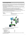
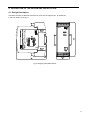
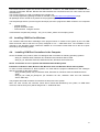
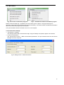
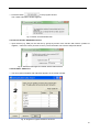
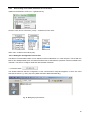
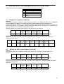
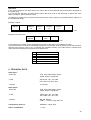
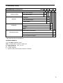
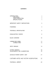
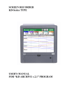
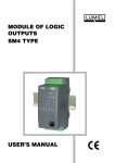
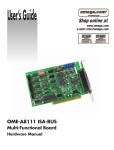
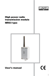
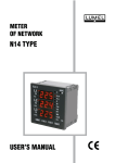
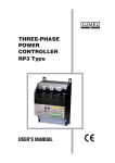
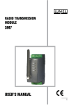
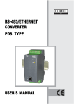
PROGRAMMABLE
LOGIC CONTROLLER
SMC TYPU
USER’S MANUAL
2
CONTENTS
1.
2.
3.
4.
APPLICATION AND DESIGN
SET OF THE DELIVERED CONTROLLER
BASIC REQUIREMENTS AND SAFETY SERVICE
DESCRIPTION OF THE DESIGN AND INSTALLATION
4.1. Design Description
4.2. Terminal Description
4.3. Installing COM Port for Windows
4.4. Installing COM Port Controllers in the Computer
5. CONTROLLER CONFIGURATION
5.1. Connection PC <--> SMC
5.2. SMC Communication <-> Devices (SM modules)
5.3.
Writing the Program in SMC
6. DESCRIPTION OF THE TRANSMISSION PROTOCOL FUNCTIONS
6.1
Readout of n-registers (Code 03)
6.2. Writing Values in the Register (Code 06)
6.3. Writing in n-registers (Code 16)
6.4. Identifying Report of the Device (Code 17)
7. ERROR CODES
8. TECHNICAL DATA
9. ORDERING CODES
10. MAINTENANCE AND GUARANTEE
4
4
5
6
6
7
8
8
9
9
12
17
18
18
18
19
19
19
20
22
23
3
1. APPLICATION AND DESIGN
The SMC programmable logic controller is the central decision module in distributed measuring and control
systems with a quick MODBUS communication (up to 115.2 kbit/s). It can service remote analogue and logic
input/output modules, measuring transducers, inverters, microcontrollers, recorders, display panels, HMI
touch screen panels, etc. Thanks to the integration of various devices we can obtain a versatile and flexible
dissipated system with a large application range.
▪ The SMC controller is programmed in the ST (Structured Text) language acc. to IEC 61131-3 standard.
The ST language is the most versatile from among IEC languages and allows the implementation of any
types of algorithms.
▪ The CPDev (control Program Developer) tool package, consisting of the CPDev compiler, CPSim program
simulator, and CPCon communication configuration, serves for the SMC programming.
▪ The package includes libraries: IEC_61131, Basic_blocks and Complex_blocks.
▪ The system designer can create own libraries with functions, functional blocks and programs.
▪ Two serial ports are destined for communication. Port 1 with two RS-485 interface systems for the
communication with devices working in the object. Port 2 with RS-485, RS-232C and USB interfaces for the
communication with the Master system through wire links.
▪ The asynchronous character communication MODBUS protocol is implemented in ports.
Parameter set of the SMC controller serial link:
- address:
1...247
1200, 2400, 4800, 9600, 19200, 38400, 57600, 115200 bit/s,
- baud rate:
- working mode :
ASCII: 8N1, 7E1, 7O1, 7N2
RTU: 8N2, 8E1, 8O1, 8N1
Exemplary network topology with the use of controllers is shown on the Fig.1,
SMC
RS485
RS485
RS232
SMC
RS485
Fig. 1. Exemplary network topology with the application of SMC controllers
2. SET OF THE DELIVERED CONTROLLER
The SMC controller set includes:
- SMC controller
1 pc
- SMC user’s manual
1 pc
- programming user’s manual
1 pc
- guarantee card
1 pc
- CD disk with the tool program
1 pc
and controllers of the USB port
When unpacking the SMC controller, please check whether the type and version code on the data plate
correspond to the order code.
4
3. BASIC REQUIREMENTS, SAFETY SERVICE
Symbols located in this user’s manual mean:
WARNING!
Warning of potential, hazardous situations.
Especially important. One must acquaint with
this before connecting the SMC controller.
The non-observance of notices marked by these symbols
can occasion the damage of the instrument.
CAUTION!
Designates a general useful note. If you observe it,
handling of the controller is made easier.
One must take note of this, when the instrument
is working inconsistently to the expectations.
Possible consequences if disregarded !
Note: The removal of the controller housing during the guarantee contract
period causes its cancellation.
In the security scope the controller meets the requirements of the
EN 61010 -1 standard.
Remarks Concerning the Operator Safety Service:
▪ All operations concerning transport, installation, and commissioning as well as
maintenance, must be carried out by qualified, skilled personnel, and national
regulations for the prevention of accidents must be observed.
▪ Before switching the controller on, one must check the correctness of connection to the network.
▪ Do not connect the controller to the network through an autotransformer.
▪ Before removing the controller housing, one must switch the supply off and disconnect
measuring circuits.
▪ One must remember that in the building installation a switch or a circuit-breaker should
be installed. This switch should be located near the device, easy accessible by the operator, and suitably
marked
5
4. DESCRIPTION OF THE DESIGN AND INSTALLATION
4.1. Design Description
The SMC controller is destined to be fixed on a 35 mm rail support (acc. to EN 60715)
in the way shown on the fig. 2.
SMC
Fig. 2. Fixing way of the SMC controller
6
4.2. Terminal Description
The supply and external signals must be connected in accordance with the fig. 3.
Individual outlets have been described in the table 1.
Caution:
One must pay a particular attention on the correct connection of external signals
(see table 1)
SMC
There are 3 signalling diodes on the frontal plate
D1 Two-colour diodes.
Green colour – continuous lighting – signals a
correct controller work.
Green colour – pulsating – signals the work in the
configuration mode.
Red colour – signals a configuration error.
D2 Green diode
Signals the data transmission from the side of a
slave device type.
D3 Yellow diode
Signals the data transmission from the side of a
master device type.
Table 1. Description of SMC Controller Outlets
USB
socket
Terminal
1
2
3
4
5
6
7
8
9, 10
11
12
13
14
15
16
Terminal description
Output +5 V ( for bus bias)
Line A of the first RS-485 interface of Port 1
Line B of the first RS-485 interface of Port 1
Line GND of the RS-485 interface of Port 1
Line GND of the RS-485 interface of Port 1
Line B of the second RS-485 interface of Port 1
Line B of the second RS-485 interface of Port 1
Output + 5V (for bus bias).
Lines of controller supply
Not used
Output TxD of the RS-232 interface of Port 2
Input RxD of the RS-232 interface of Port 2
Line
GND of the RS-232 and RS-485
interfaces of Port 2
Line A of the RS485 interface of Port 2
Line B of the RS-485 interface of Port 2
Fig. 3. Electrical connections of the SMC controller.
The controller has two serial ports, Port 1 and Port 2.
The port 1 is destined for communication with devices of Slave type.
Two RS-485 interface systems are added to the Port 1. The
operation of both systems is identical. Interface systems are electrically connected and galvanically isolated
from the remainder of the system. Interface lines are connected to terminals 1, 2, 3, 4 for the first port, and 5,
6 , 7 , 8 for the second port. The RS-485 bus enables the direct connection to 32 devices with RS-485
interface. The maximal bus length depends on the baud rate and is included in limits from several dozens of
meters for high speeds, up to ca 1.2 km for low speeds.
The port 2 is destined for the controller configuration with the PC computer.
The Port 2 includes RS-485, RS-232 and USB interfaces. The RS-485 interface enables the connection of
the controller to the RS-485 serial bus, its lines has been led out to terminals 14, 15 and 16. RS-232 and
USB interfaces are destined to connect with the Master system.
7
The RS-232 interface signals are led out to terminals 12, 13 and 14. The USB interface is available on the
controller frontal plate. RS-485, RS-232 and USB interfaces are connected to the Port 2 and cannot be used
simultaneously.
The current program on a CD is included in the controller set.
The current programming package for SMC is included on the www.lumel.com.pl/download page.
All updatings can be carried out by means of the programming package runs on this page.
The tool package CPDev (Control Program Developer) serves to program the SMC controller. It is composed
of:
- compiler CPDev,
- program simulator CPSim
- communication configurer CPCon.
Three libraries complete the package - IEC_61131, Basic_blocks and Complex_blocks.
4.3. Installing COM Port for Windows
The controller USB Port takes advantage of the program which is created in the system by the new USB
Serial Converter device and the Port (Com) assigned to him – USB Serial Port. The installation of the
controller in the Windows system causes the addition of a successive serial COM Port to the list of ports
serviced by the operating system.
4.4.
Installing COM Port Controllers in the Computer.
On the CD added to the product, there are catalogues with controllers for following operating systems:
- WIN_XP: Windows 2000, Windows XP, Windows Vista, Windows Server 2003.
- WIN_XP_64: Windows Vista x64, Windows XP x64, Windows Server 2003 x64.
NOTE: Controllers do not co-operate with Windows 98 and ME systems.
Installation in Windows 2000, Windows XP, Windows Vista and Windows Server 2003 systems.
In order to install controllers for these systems, one must start the program realizable from the catalogue
with the controller for the given system:
- WIN_XP\CDM_Setup.exe (for Windows 2000, Windows XP, Windows Vista and Windows Server
2003)
- WIN_XP_64\ CDM_x64_Setup.exe (for Windows XP x64, Windows Vista x64 and Windows
Server 2003 x64).
This program will install controllers for new devices and ports in the system.
Next, one must connect the controller, which will be found and identified by the system, as USB serial
converter, and the Port (Com) will be assigned to it – USB Serial Port.
8
5. CONTROLLER CONFIGURATION
NOTE : The language description and examples of controller programming are included in the
programming manual.
Before proceeding to the controller configuration, one must prepare the
controlling program taking advantage of tools included in the controller set.
5.1. PC SMC Connection
5.1.1 Installation of the USB Controller
If the PC computer has not an installed USB port controller for the SMC, one must install it through the
CDM_Setup.exe program from the CD acc. to the section 4.4. It generates, that the USB port will be serviced
as a serial port.
PC↔SMC Cable
Connect the USB port of the computer to the USB port of the SMC controller (on the frontal plate).
5.1.2 Number of the USB Port
Read out in the Device Manager of the Windows system, which COM port is the USB port connected to the
SMC controller.
• Menu Start > Settings > Control panel > System > Hardware > Device Manager
In the appearing window, develop Ports:
In the case like above, USB is the COM5 port.
5.1.3 Starting the CPCon configurer
One can start the configurer in three ways:
a) Menu CPDev: Project > Run the configurer
Fig.4. Starting the configurer from the Project Menu.
9
b) Tools > Configurer
Fig. 5. Starting the configurer as tools
c) Menu start: CPDeV > CPCon
Fig. 6 Starting the configurer from the system menu
The first way is applied directly after the Project compilation. The two next require the file import from the
compiled project. After starting, the configuration window of the CPCon communication appears
Fig. 7. Table of communication tasks
The communication task table has a basic meaning. It defines which transactions of the MODBUS protocol,
i.e. exchange of messages queries – responses (readout) or commands – confirmation (write) will take
place. Transactions are named here communication tasks.
10
5.1.4 Menu CPCon
Fig. 8. File menu of the CPCon program
Fig. 9. Transmission menu of the CPCon program
Buttons under the table (Fig. 7) realizes a part of functions given in options. The project file import is
necessary, when CPCon was started in the second or third way. The read out metric contains documentation
data of the carried out program by the controller.
The synchronization sets the controller clock acc. to the computer.
5.1.5 Transmission Settings
• Transmission > Settings
The Settings window with Communication tags, Program Settings and Update, appear in the window.
• Vertical communication
The Tag serves to set PC ↔ SMC communication parameters. The port number issues from the Device
Manager of the PC computer.
Fig. 10. Setting of the PC ↔ SMC communication
11
• Horizontal communication
Communication parameters SMC ↔ in/out modules can be selected from the tag (or other devices).
Parameters must be the same as they set in modules.
The 8N1 mode selected below means 8-bit data, odd parity (N) and 1 stop bit.
Fig. 11. Setting of the PC SMC in/out module communication
• Program Setting
Language selection.
Fig. 12. Language setting
5.2 SMC Communication Devices (SM Modules)
For the SMC controller communication with object devices can serve :
a) global variables, which addresses, e.g. START, STOP, ALARM, have been assigned to,
b) COM_SM1, COM_SM2, etc, communication blocks, dedicated for SM module.
The communication is configured by fulfilling a suitable number of rows of the task table.
Each line represents one communication task of the SMC controller.
The filling can me made directly from the table (the right mouse key adds or erases the row, or by means of
the task creator (button) composed of several windows:
12
• Press the button
in the program window.
The creator information window appears
Fig. 13. Creator of communication tasks
5.2.1 Device Number. MODBUS Function
• Input devices (e.g. SM5) can be read out by groups by means of the function with Code 3 (readout of
registers , named FC3 here (Function Code 3). The first window can have the shape like below.
Fig. 14. Definition of the target slave number and the readout function
5.2.2 Variables. Addresses
• The list of global variables with addresses appears in the creator window.
Fig. 15. Assignment of global variables to the device.
13
Among global variables of our project, we highlight input variables.
The logic addresses of variables are e.g. 0,1, 2, and the dimension of each is a byte. Addresses of input
variables are successive numbers, then the readout by groups (by blocks) is suitable.
Note. If the list is empty, then the click of the (write the variables list in) allows to import variables from the
chosen file in the being opened window.
5.2.3 Device. Beginning Address.
• Example of the SM5 module device association for communication tasks. For example, the START
variable register has the address 4003.
Fig. 16. Assignment to the device and definition of the beginning address.
5.2.4 Priority. Timeout
Communication tasks defined by type lines of the main table are made in breaks, which after performing the
program time remains to the end of each cycle. If the break is important, the task can be carried out several
times. The task with a normal priority is carried out twice rarely than the task with a high priority, and the task
with a low priority, three times rarely. Timeout means the maximal period of time during which the exchange
of messages with the device has to be finished.
• It is assumed that the communication task from SM5 will have a normal priority and the exchange of
messages has to be finished during 500 ms (timeout).
Fig. 17. Assignment of the priority and waiting time.
14
5.2.5. Control Variables
The last creator window serves for the configuration of transmission control, if the appropriate fragment of
the program forecasts it. It is indicated in the window, to which of variables has to be write the information
about the correctness or incorrectness of the communication, which of the variable is destined to write the
communication time in, and by means of which, one can enable or disable communication tasks.
Control variables are used in advanced projects.
Fig. 18. Control variables
5.2.6 Creation of the Communication Task
•
Press the button
.
The first line with data set in the creator appears in the table of communication tasks and with it, the
conversion of registers into bytes, 16 → 8 bit.
Fig. 19. View of the table after the task configuration.
15
5.2.7.
Direct Filling of the Table (alternative for the Creator).
Addition and elimination of the row – right Mouse key
Function code, kind of conversion, priority – selection from the menu.
Other cells – written in the ordinary way.
5.2.8. Writing the Configuration into the File.
The table of communication tasks can be utilized in later modifications or in other Projects. The file with the
table is also indispensable when the CPSim Simulator has to stimulate the operation of devices added to the
controller. The CPCon configurer write files with the XMC extension.
• Press the button
The window Write file with the configuration of the communication subsystem appears, in which one must
write the file name, e.g. Start_Stop.xmc (XMC extension added automatically).
Fig. 20 Writing the project to the file
16
5.2.9. Configuration Readout ( for Check, Modification, ETC.)
• Press the button
Select the file in the appearing window Open file with the confirmation of the communication subsystem
and click Open.
Fig. 21 Reading in the project to the file
In case of the file Start_Stop.xmc, the table of communication tasks will be looked like previously.
5.3 Writing the Program in SMC
• Before writing, it is worth to open the lower part of the window by clicking Communication monitoring. It
allows to check if the write has proceeded correctly.
• Press the button
• The window of the project specification (metric) appears, which with the program will be written in the
SMC controller.
During the write, check information is displayed in the Communication monitoring window.
Fig. 22. Exemplary communication window PC SMC
After writing the program, the SMC controller begins instantly its execution, communicating
with object devices.
17
6.
DESCRIPTION OF THE TRANSMISSION PROTOCOL FUNCTIONS
Following functions of the MODBUS protocol were implemented in the controller.
code
03
06
16
17
Meaning
Readout of n-registers
Write of a single register
Write of n-registers
Identification of the slave
device
6.1. Readout of n-registers (code 03)
Request:
The function enables the readout of values included in register, in the addressed slave device. Registers
are 16 or 32-bit units, which can include numerical values related to process variables a.s.l.
The request frame is defined by the first 16-bit address of the register and the number of registers to
readout. The meaning of the register contents about given addresses can be different for different device
types. The function is not available in the broadcast mode.
Example: Readout of 3 registers beginning from the register with 6B h address.
address
function
11
03
register
address
Hi
00
register
address
Lo
6B
number of number of checksum
registers
registers
Hi
Lo
00
03
7E
LRC
Response:
Register data are packed beginning from the lowest address: first the older byte, next the younger register byte.
Example: Response frame.
address function numb. value of value of
of
reg.107 reg.107
bytes
Hi
Lo
11
03
06
02
2B
6.2.
value in
reg.108
Hi
00
value in
reg.108
Lo
00
value in
reg.109
Hi
00
value in checksum
reg.109
a
Lo
64
55
LR
C
Writing the Value in the Register (Code 06)
Request:
The function enables the modification of the register contents. It is available in the broadcast mode.
Example:
address function register
register
value
value
checksum
address address
Hi
Lo
Hi
Lo
11
06
00
87
03
9E
C1
LRC
Response:
The correct response for the request of the value write in the register is the message retransmission after
performing the operation.
Example:
address function register
register
value
value
checksum
address address
Hi
Lo
Hi
Lo
11
06
00
87
03
9E
C1
LRC
18
6.3.
Writing in n-registers (Code 16)
Request:
The function is available In the broadcast mode. It enables the modification of the register contents.
Example: Write of two registers beginning from the register with the address 136.
address funct. regist.
regist.
numb. numb. numb. data
data data data
checkaddress address of reg. of reg.
of
Hi
Lo
Hi
Lo
sum
Hi
Lo
Hi
Lo
bytes
11
10
00
87
00
02
04
00
0A
01
02
45
LRC
Response:
The correct response includes the slave unit address, initial address and the number of written addresses.
Example:
address function register register
number
number
checksum
address address of registers of registers
Hi
Lo
Hi
Lo
11
10
00
87
00
02
56
LRC
6.4. Report Identifying the Device (Code 17)
Request:
The function allows the user to obtain information about the device type, status and configuration depending
on it.
Example:
address function
11
11
checksum
DE
LRC
Response:
The field „Device identifier” in the response frame means the unique identifier of the given device class,
however remaining fields include parameters dependent on the device type.
7. ERROR CODES
When the master device transmits the request to the slave device then, with the exception of messages in
the broadcast mode, it waits for a correct response. After transmitting the request of the master unit, one of
the four possible events can appear:
If the slave unit receives the request without a transmission error and can perform it correctly, then
returns the correct response.
If the slave unit does not receive the request, not any response is returned. In the program of the master
device, timeout conditions will be fulfilled for the request.
If the slave unit receives the request, but with transmission errors (parity error, LRC or CRC checksum),
not any response is returned. Timeout conditions for request will be fulfilled in the master device program.
If the slave unit receives the request without transmission errors, but cannot perform it correctly (e.g.
If the request is a readout of a not existing bit output or register), then returns the response including the
error code, informing the master device about the error cause.
The message with an erroneous response includes two fields differentiating it from the correct response.:
Function Code Field:
In the correct response, the slave unit retransmits the function code from the request message on the
response code field.
All function codes have the most significant bit (MSB) equal 0 ( code values are below 80h).
In the erroneous terror, the slave device set the MSB bit of the function code on 1. This occasions, that the
function code value in the erroneous response is exactly higher of 80h than it had been in the correct
response.
On the base of the function code with the set MSB bit, the master device program can begin the erroneous
response and check the error code in the data field.
19
Data Field:
In the correct response, the slave device can return data on the data field (some information requested by
the master unit).
In the erroneous response, the slave device returns the terror code on the data field. It defines the slave
device conditions, which causes the error.
An example of master device request and erroneous slave device response is presented below. Data are in
the hexadecimal shape.
Example: request
slave
address
function
0A
01
variable
address
Hi
04
variable
address
Lo
A1
number of
variables
Hi
00
number of
variables
Lo
01
checksum
4F
LRC
Example: erroneous error
slave
address
0A
function
81
error
code
01
checksum
73
LRC
In this example, the master device addresses the request to the slave unit numbered 10 (oHa).
The function with the code (01) is not implemented in the concentrator, then the device returns the erroneous
response with the error code nr 01. It indicates the forbidden function in the slave device. Possible error
codes and their meanings are presented in the table below.
code
01
02
03
04
05
meaning
forbidden function
forbidden data address
forbidden data value
request being in realization
impossible request realization
8. TECHNICAL DATA
Serial port I:
- baud rate
1200, 2400, 4800, 9600, 19200,
38400, 57600, 115200 bit/s
- mode
ASCII: 8N1, 7E1, 7O1,7N2
RTU: 8N2, 8 E1, 8O1, 8N1
- interface
2 x RS-485
Serial port II:
- baud rate
1200, 2400, 4800, 9600, 19200,
38400, 57600, 115200 bit/s
- mode
ASCII: 8N1, 7E1, 7O1,7N2
RTU: 8N2, 8 E1, 8O1, 8N1
- interface
RS-485, RS-232
USB 1.1 – wire no longer than 3 m
Transmission protocol:
MODBUS – ASCII, RTU
Power consumption
≤ 4 VA
20
Rated operating conditions:
- supply voltage
- supply voltage frequency
- ambient temperature
- relative air humidity
- external magnetic field
- working position
Storage and transport conditions:
- ambient temperature
- relative air humidity
20…24…40 V a.c./d.c. or
85…230…253 V a.c./d.c.
40…50/60…440 Hz
0…23…55ºC
< 95% (inadmissible condensation of
water vapor)
< 400 A/m
any
-20…70 ºC
< 95% (inadmissible condensation of
water vapor)
Ensured protection levels:
- from frontal housing side
- from terminal side
IP 40
IP 20
Overall dimensions:
45 x 120 x 100 mm
Weight :
0.25 kg
SMC casing:
for mounting on a 35 mm DIN rail
Electromagnetic compatibility:
- noise immunity
- noise emissions
acc. to EN 61000-6-2
acc. to EN 61000-6-4
Safety requirements acc. to EN 61010-1:
- installation category
- pollution level
III
2
Maximal phase-to-earth working voltage:
- for supply circuits
- for other circuits
300 V
50 V
21
9. ORDERING CODES
SMC-
PROGRAMMABLE CONTROLLER
X
85…253 V a.c/d.c.
1
20…40 V a.c/d.c.
2
XX
X
X
Supply voltage:
Version:
standard
00
non-standard settings
NS
custom-made*
XX
Polish
P
English
E
other
X
Language:
without extra l requirements
Acceptance tests:
0
with an extra quality inspection certificate
1
acc. to customer’s request *
X
* After agreeing with the manufacturer
ORDERING EXAMPLE
The code: SMC-1- 00- E-1 means:
SMC – programmable controller of SMC type
1 – supply voltage: 85…253 V a.c./d.c.
00 – standard version
E – English language
1 – delivered with an extra quality inspection certificate
22
10. MAINTENANCE AND GUARANTEE
The applied battery in the SMC controller requires replacement every 5 years. In order to
replace the battery, one must send the controller to the Manufacturer’s Service
Department.
In case of some incorrect operations:
1. In the period given in the annexed guarantee card
One should take the controller down from the installation and return it to the
Manufacturer’s Quality Control Dept.
If the unit has been used in compliance with the instructions, the Manufacturer guarantees
to repair it free of charge.
2. After the guarantee period:
One should turn over the controller to repair it in a certified service workshop.
The disassembling of the housing causes the cancellation of the granted guarantee.
Our policy is one of continuous improvement and we reserve the right
to make changes in design and specifications of any products as
engineering advances or necessity requires and revise the above
specifications without notice.
23
CONTROL
MEASUREMENT
RECORDING
SALES PROGRAM
DIGITAL AND BARGRAPH PANEL METERS
MEASURING TRANSDUCERS
ANALOG PANEL METERS (DIN INSTRUMENTS)
DIGITAL CLAMP-ON METERS
INDUSTRIAL PROCESS CONTROLLERS
CHART AND PAPERLESS RECORDERS
POWER CONTROL UNITS AND SOLIDE-STATE RELAYS
ELECTRONIC WATT-HOUR METERS
▪ INTEGRATION ELEMENTS OF MEASURING NETWORKS
▪ LARGE-SIZE ALPHANUMERICAL DISPLAY PANELS
ACCESSORIES FOR MEASURING INSTRUMENTS ( SHUNTS)
CUSTOM - MADE PRODUCTS
WE ALSO OFFER OUR SERVICES IN THE PRODUCTION OF:
ALUMINIUM ALLOY PRESSURE CASTINGS
PRECISION ENGINEERING AND THERMOPLASTICS PARTS
SMT ASSEMBLY SERVICES
MOUNTING OF SUBCONTRACTED ELECTRONIC DEVICES
QUALITY PROCEDURES:
According to ISO 9001 and ISO 14001 international requirements.
All our instruments have CE mark .
For more information, please write to or phone our Export Department
SMC-09/1
January 2010
Lubuskie Zakłady Aparatów Elektrycznych - LUMEL S.A.
ul. Sulechowska 1
65-022 Zielona Góra – Poland
Export Department:
Tel.: (48-68) 32 95 1 00 (exchange)
Fax: (48-68) 32 95 1 01
Tel.: (48-68) 329 53 02
Fax: (48-68) 325 40 91
e-mail:[email protected]
http://www.lumel.com.pl
e-mail: [email protected]
24