1
GB
STEAM/CONVECTION GAS OVENS
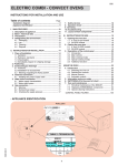
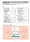
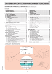
INSTALLATION AND OPERATING INSTRUCTIONS
Summary
(for the United Kingdom)
Page
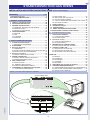
- Installation diagrams......................................................... 4
APPLIANCE IDENTIFICATION.......................................... 37
7.2 REPLACING THE ..................................................... 45
7.3 REPLACING THE GAS VALVE ................................ 45
7.4 GAS VALVE ADJUSTMENT ..................................... 45
7.5 TABLE 2: NOZZLES AND ADJUSTMENTS / GAS TYPES.. 46
7.6 GAS TYPE STICKER ............................................... 47
8. SAFETY DEVICE .......................................................... 47
9. OPERATION CHECK .................................................... 47
10. MAINTENANCE .......................................................... 47
11. BRIEF TROUBLESHOOTING GUIDE ........................ 47
12. POSITIONING OF MAIN COMPONENTS ................. 47
I. GENERAL CHARACTERISTICS...................................... 38
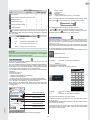
1. TABLE 1: TECHNICAL DATA....................................... 38
2. APPLIANCE DESCRIPTION ........................................ 39
3. GENERAL INSTRUCTIONS ......................................... 39
3.1 PERSONAL PROTECTION EQUIPMENT ............... 39
3.2 RESIDUAL RISKS .................................................... 40
3.3 TECHNICAL DATA PLATE ...................................... 40
4. THE ENVIRONMENT .................................................... 40
4.1 PACKING .................................................................. 40
4.2 USE .......................................................................... 40
4.3 CLEANING ............................................................... 40
4.4 DISPOSAL................................................................ 40
III. OPERATING INSTRUCTIONS ....................................... 48
1. OVEN DOOR OPENING ............................................... 48
1.1 6 AND 10-RACK MODEL ......................................... 48
1.2 20-RACK MODEL..................................................... 48
2. Oven door closing ....................................................... 48
2.1 6 AND 10-RACK MODELS ....................................... 48
2.2 20-RACK MODELS .................................................. 48
3. DESCRIPTION OF CONTROL PANEL ......
m 49
3.2 MAIN FUNCTIONS AND SYMBOLS ........................ 49
4. CONTROL PANEL USE ................................................ 52
4.1 SWITCHING THE OVEN ON ................................... 52
4.2 SWITCHING THE OVEN OFF ................................. 52
4.3 SELECTING CONTROLS (AREAS)......................... 52
II. INSTALLATION INSTRUCTIONS .................................... 41
1. PLACE OF INSTALLATION.......................................... 41
1.1 REFERENCE STANDARDS .................................... 41
2. POSITIONING ............................................................... 41
3. Burnt gas discharge .................................................... 41
3.1 FOREWORD ............................................................ 41
3.2 INSTRUCTIONS REGARDING THE EXHAUST SYSTEM . 42
3.3 INSTALLATION OF ACCESSORIES ........................ 42
4. Electrical connection .................................................. 42
4.1 POWER CABLE INSTALLATION ............................. 43
5. WATER CONNECTION ................................................. 43
5.1 SUPPLY WATER CHARACTERISTICS ................... 43
5.2 WATER DRAINING SYSTEM................................... 44
6. GAS CONNECTION ...................................................... 44
6.1 INSTRUCTIONS ..................................................... 44
6.2 NOMINAL HEAT OUTPUT ..................................... 45
6.3 SUPPLY PRESSURE CHECK ......................... 45
7. CONVERSION TO ANOTHER TYPE OF GAS ............. 45
7.1 ACCESSING COMPONENTS ................................ 45
OVEN USE ............................................................................. 52
4.4 MANUAL................................................................... 53
4.5 AUTOMATIC ............................................................. 58
4.6 PROGRAMS............................................................. 60
4.7 CLEANING ............................................................... 60
4.8 SETTINGS................................................................ 61
5. SWITCHING OFF IN CASE OF A FAULT ..................... 63
6. CLEANING AND MAINTENANCE................................ 63
6.1 STEAM GENERATOR PERIODICAL MAINTENANCE . 64
6.2 REPLACING CONSUMABLE COMPONENTS ........ 65
6.3 PARTICULAR CLEANING ........................................ 65
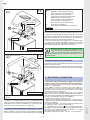
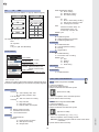
APPLIANCE IDENTIFICATION
"Technical Data" plate
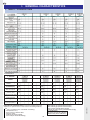
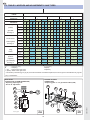
2. TABLE 1: TECHNICAL DATA
6 GN 1/1
A^
5954 962
007 00
01
5958
B^
°
**
400
°
**
230
°
**
200
37
GB
I. GENERAL CHARACTERISTICS
1. TABLE 1: TECHNICAL DATA
for AUSTRALIA
6GN2/1
(AOS061E)
AOS061GTG1
AOS061GTD1
FCZ061GTG
FCZ061GTD
MODEL
10 GN 1/1
10 GN 2/1
20 GN 1/1
AOS101GTG1
AOS101GTD1
FCZ101GTG
FCZ101GTD
AOS102GTG1
AOS102GTD1
FCZ102GTG
FCZ102GTD
AOS201GTG1
AOS201GTD1
FCZ201GTG
FCZ201GTD
20 GN 2/1
AOS202GTG1
AOS202GTD1
FCZ202GTG
FCZ202GTD
o
x
°
x
o
x
o
x
°
x
o
x
PHASES (No)
1+N
1+N
1+N
1+N
13
1+N
BS/P connection Ø
1/2" M
1/2" M
1/2" M
1/2" M
25
1/2" M
Natural Gas inlet supply
pressure - (KPa)
1.13
1.13
1.13
1.13
4,5°°
1.13
Propane Gas inlet supply
pressure (KPa)
2.75
2.75
2.75
2.75
4,6
2.75
Propane Gas total
consumption (MJ/h)
**
67.2
159
174.2
251.2
4,6
356.4
Natural Gas total
consumption (MJ/h) **
67,2
137
174.2
219.2
4,6
373.4
CONVECTOR
BOILER **
°
x
Information on sound emissions: The functional components of the
appliances in question have a noise level not exceeding 70 dB (A).
G20 natural gas (Hi=34.02 MJoule/m3)
G25 natural gas (Hi=29.25 MJoule/m3)
LPG (Japan) (Hi=46.36 MJoule/kg)
Natural gas 13A (Japan) (Hi=46.05 MJoule/kg)
for AUSTRALIA
Propane Gas (Hi=95.8 MJ/m3)
Natural Gas (Hi=37.8 MJ/m3)
**
Gas consumption was calculated considering:
- Temperature 15°C;
- Atm. pressure 1013.25 mbar;
- Net heat value :
G30 (Hi=45.65 MJoule/kg)
G31 LPG (Hi=46.34 MJoule/kg)
38
5954 007 01
6 GN 1/1
n° GRIGLIE
GB
2. APPLIANCE DESCRIPTION
• Before installing and using the appliance, carefully read this handbook as
it provides important information and
instructions on safe installation, use and
maintenance.
This handbook concerns various appliance models.
For further information regarding your model, refer to Table
1"Technical Data".
The appliance has the following features:
• Digital indication of temperature.
• Thermostatic probe for measuring the product's "core" temperature (core probe).
• Constant monitoring of cooking parameters during the entire cycle.
• Periodical emptying and subsequent automatic cleaning of the
steam generator to prevent excess scaling (depending on the model).
• Signalling the need for periodical boiler maintenance; see relevant section (depending on the model).
• Compartment rapid fume extraction device for gratinating, with
automatic activation.
• AIR-BREAK anti-backflow device for preventing backflow from
the drainage system entering the oven (depending on the model).
• Compartment lamps.
• Door opening double-action safety mechanism to prevent burns
(depending on the model).
• Door with double glass: better comfort in the kitchen and low
surface temperatures.
• Cycle for daily cleaning of oven compartment (CLEANING
SYSTEM) (depending on the model).
• Self-diagnosis for possible malfunctions by means of signalling
with identification codes.
• Keep this handbook for further consultation by the various operators, or in
case the appliance is resold.
Attention: Appliance installation, any maintenance
work and conversion to another type of gas must only
be carried out by professionally qualified personnel
authorised by the Manufacturer.
• This appliance is intended for collective use and is expressly
designed for cooking food. Any other use is deemed improper.
The appliance must only be used by trained staff.
• This appliance is not intended for use by people (including children) with limited physical, sensory or mental abilities or without
experience and knowledge of it, unless they are supervised or
instructed in its use by a person responsible for their safety.
• Switch the appliance off in case of fault or poor operation.
• F o r a n y r e pa ir s , o n ly c o n s u lt a n
A f te r - S a l e s C e n tr e a u th o r i s e d
by the manufacturer and demand original replacement parts.
Failure to observe the above can compromise appliance
safety and invalidates any form of warranty.
For UK and COMMONWEALTH only:
This appliance is designated as a forced draught burner,
therefore the appliance is classed as COMCAT5 and only
installers who held the relevant gas qualification are allowed
to install/commission and service this product.
WARNING:
Failure to use a qualified/authorised installer WILL INVALIDATE THE WARRANTY conditions and may render the
appliance inoperative.
If any doubt please consult the manufacturer for further advice.
Under no circumstances must this product be used unless
installed and /or commissioned by a qualified engineer.
• Do not clean the appliance with direct
jets of water.
• Do not use products containing chlorine (chlorine bleach,
hydrochloric acid, etc.), even if diluted, to clean the steel parts.
• Do not use corrosive substances (e.g. muriatic acid) to clean
the oor under the appliance.
• For further details see the section "Cleaning and maintenance ".
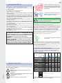
3.1 PERSONAL PROTECTION EQUIPMENT
Give below is a summary table of the Personal Protection
Equipment (PPE) to be used during the various stages of the
machine’s service life.
Protective
garments
Safety
footwear
Gloves
Glasses
Ear
protectors
Mask
Safety
helmet
Stage
Transport
Handling
Unpacking
Assembly
Normal use
3. GENERAL INSTRUCTIONS
Routine
cleaning
Extraordinary
cleaning
The following symbols are used in the manual to mark and identify
the various types of hazards:
Maintenance
ATTENTION!
DANGER FOR THE HEALTH AND SAFETY OF
OPERATORS.
5954 962
007 00
01
5958
X
Adjustments
Dismantling
Scrapping
Key:
ATTENTION!
DANGER OF ELECTRIC DISCHARGE (Electrocution)
- DANGEROUS VOLTAGE.
X
X
X
X
X
X
X
X
X
X
X
X
X (*)
X
X
PPE REQUIRED
PPE AVAILABLE OR TO BE USED IF NECESSARY
ATTENTION!
RISK OF DAMAGE TO THE MACHINE.
PPE NOT REQUIRED
(*) During Normal use, gloves must be heatproof to protect hands
when removing the hot pan from the appliance.
39
GB
Failure to use the personal protection equipment by operators,
specialised technicians or users can involve exposure to chemical
risk and possible damage to health.
Hz ......................... power supply frequency
kW ........................ max. power input
A ........................... current absorption
EL: ........................ [H] electrical prearrangement
Cat ........................ gas category
P mbar .................. gas pressure
∑ Qn ..................... gas power
G30-Lb1-...G120... consumption of various gas types
Type-Bauart-type .. construction type (fume exhaust system)
[ I ] ........................ protection rating
CE ........................ CE marking
0051 EN 203-1 ..... reference standards
3.2 RESIDUAL RISKS
The machine has several risks that were not completely eliminated from a design standpoint or with the installation of adequate
protection devices.
For the Customer’s complete information, the residual risks remaining on the machine are indicated below: such actions are to
be considered incorrect and therefore strictly forbidden.
RESIDUAL
RISK
DESCRIPTION OF HAZARDOUS
SITUATION
Slipping or
falling
The operator can slip due to water or dirt
on the floor.
Burns
The operator deliberately or unintentionally touches some components
inside the machine or dishes at the outfeed without using gloves or without
allowing them to cool.
Danger of
electric
discharge
(Electrocution)
Contact with live parts during maintenance operations carried out with the
electrical panel powered. The operator
intervenes (with a power tool or without
disconnecting the power to the machine)
lying down on the wet floor.
Falling from
above
The operator intervenes on the machine
using unsuitable systems to access
the upper part (e.g. rung ladders, or
climbs on it).
Tipping of loads
During maintenance on the machine or
the packing containing the machine
with the use of unsuitable accessories or
lifting systems or with load unbalanced.
When handling pans containing food.
Chemical
Contact with chemical substances (e.g.
detergent, rinse aid, scale remover,
etc.) without taking adequate safety precautions. Therefore always refer to
the safety cards and labels on the products used.
4. THE ENVIRONMENT
4.1 PACKING
• All the packing materials are environmentally friendly. They can
be stored without risk or burned in a special waste incineration
plant. Recyclable plastic components are marked as follows:
PE
pp
polyethylene:
polypropylene:
polystyrene
outer wrapping, instructions bag, gas
nozzle bag.
roof packing panels, straps
foam: corner protectors
PS
4.2 USE
• Our appliances are designed and optimised with laboratory
testing in order to offer high performance and efficiency. In any
case, to reduce energy consumption (electricity, gas and water),
avoid using the appliance empty for long periods or in conditions
that compromise optimum efficiency (e.g. door open). Also, if
possible, preheat the appliance immediately before use.
4.3 CLEANING
• In order to reduce the emission of pollutants into the environment,
clean the appliance (externally and when necessary internally)
with products that are over 90% biodegradable.
4.4 DISPOSAL
• At the end of the product's working life, make sure it is not dispersed in the environment.
• Our appliances are manufactured using more than 90% metals
(stainless steel, iron, aluminium, galvanised sheet, copper, etc.)
which can be recycled by means of the conventional recovery
structures, in compliance with the current regulations in the
country of use.
• Make the appliance unusable by removing the power cable
and any compartment or cavity closing devices (when present)
in order to avoid the risk of someone becoming trapped inside.
3.3 TECHNICAL DATA PLATE
L
Meaning of fields given on the plate:
F. Mod. .................. factory description of product
Comm. Model ....... commercial description
Ser. Nr. ................. serial number
ELX ....................... manufacturer: Electrolux Professional spa
Viale Treviso, 15
33170 Pordenone (Italy)
Made in EU ........... place of manufacture
99-9999 ................ month/year of manufacture
PNC: ..................... production number code
EL: ........................ [C] power supply voltage, [D] phase
for AUSTRALIA
• Warnings:
• Do not store or use gasoline or other flammable vapours,
liquids or items in the vicinity of this or any other appliance.
• Do not spray aerosols in the vicinity of this appliance
while it is in operation.
• Never check for leaks with an open flame
• The appliance is not suitable for a marine environment.
40
5954 007 01
on the product indicates that this product
The symbol
should not be treated as domestic waste, but must be correctly
disposed of in order to prevent possible negative consequences
for the environment and the human health.
Regarding the recycling of this product, please contact the sales
agent or dealer of your product, your after-sales service or the
appropriate waste disposal service.
GB
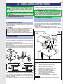
II. INSTALLATION INSTRUCTIONS
right side and back must remain 10 cm from any surface.
• Position the appliance on a flat surface and, if necessary, adjust
the height of the worktop by means of the adjustable feet.
• The appliance is not suitable for built-in installation.
Attention: The external panels of the oven must be
removed for the operations described in this section.
As the unit must be operating in order to carry out
some adjustments, pay maximum attention to the live
parts.
Attention:
Make sure the steam coming from the oven discharge or adjacent appliances does not reach
the aeration vents (for cooling internal components), located at the bottom of the appliance.
Attention: Maintenance in the upper part of the appliance requires the use of ladders with protection
(guard).
1. PLACE OF INSTALLATION
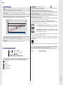
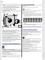
3. BURNT GAS DISCHARGE
• Only install the appliance in a suitably ventilated place.
3.1 FOREWORD
In relation to the combustion technology used, Steam Convection
gas ovens are classified according to their "Construction Type".
The regulations provide for a specific burnt gas discharge system
for each of these.
Consequently, before installing the discharge system:
a) identify the "Construction type" of the model in Table 1
(technical data) or on the dataplate;
1.1 REFERENCE STANDARDS
• Install the appliance in compliance with the current local and
national regulations.
for AUSTRALIA
• This appliance shall be installed only by authorised persons
and in accordance with the manufacturer’s installation
instructions, local gas fitting regulations,municipal building
codes, electrical wiring regulations, local water supply
regulations, AS5601-gas installation, health authorites and any
other statutory regulations.
CONSTRUCTION TYPE
A3
1a
2. POSITIONING
• Unpack the appliance, carefully remove the protective film from
outside panels, making sure no traces of glue remain. If necessary,
remove them using a suitable solvent.
Remove the packing using protective gloves.
Lift the appliance with a lift truck, remove the base, and position
it the place of use.
Remove the protective film and make sure the packing material
is not dispersed in the environment but disposed of according to
the current regulations in the country where the product is used.
20 GN
6-10 GN
20 GN
6-10 GN
DIRECT NON-DUCTED DISCHARGE UNDER EXTRACTOR HOOD
4 23 ” 120 mm
32
5 1 ” 130 mm
8
6-10 GN
5954 962
007 00
01
5958
KEY:
11 7 ” 300 mm
64
A:
B:
C:
E:
20 GN
• For disposal of the packing, see the section "The Environment"
• For the overall space required and connection dimensions,
refer to the installation diagrams given on the first pages of this
instruction handbook.
• The left side of the appliance must remain at least 50 cm from
other surfaces to enable maintenance operations, whereas the
41
F:
G:
*:
Manifold / draught damper accessory
(to be ordered from the manufacturer)
Steam generator burnt gas outlet
Compartment convector burnt gas outlet
Adapter ring for commercial ducts
(to be ordered from the manufacturer)
Conical sections for single outlet
(to be ordered from the manufacturer)
Fixing screws (supplied);
Commercial extension pipes (not supplied)
SILICONE :
Apply silicone sealant between the contact surfaces
GB
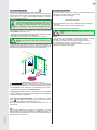
1b
CONSTRUCTION TYPE
B13
KEY:
A:
B:
C:
E:
F:
Tmax=350°C
2D
G:
*:
øD
SILICONE :
Apply silicone sealant between the contact surfaces
E
*
B
than that of burnt gases produced by the appliance (see point 1.1).
C
SILICONE
Manifold / draught damper accessory
(to be ordered from the manufacturer)
Steam generator burnt gas outlet
Compartment convector burnt gas outlet
Adapter ring for commercial ducts
(to be ordered from the manufacturer)
Conical sections for single outlet
(to be ordered from the manufacturer)
Fixing screws (supplied);
Commercial extension pipes (not supplied)
A
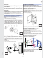
In case of burnt gas exhausting under an extractor hood, respect
the distance (shown in the figure) between the top of the exhaust
pipe and the lowest point of the hood filters. This distance is
defined on the basis of exhaust pipe diameter "D".
In the case of discharge to the outside or to a central flue (Fig.
"1c"), the exhaust ducting must NOT be longer than 3 metres
(total length) or have any reductions in diameter, and must be
periodically inspected and cleaned when necessary.
G
Attention: Since burnt gases (see figure) can reach
very high temperatures, check the materials extension
ducts and extractor hood filters are made from. Also
make sure to periodically check the filters which, if
clogged with grease and grime, will reduce the efficiency of the
extraction system.
Not AUSTRALIA Version
DISCHARGE WITH MANIFOLD UNDER EXTRACTOR HOOD
1c
CONSTRUCTION TYPE
B13
3.3 INSTALLATION OF ACCESSORIES
Accessories can be easily installed by following the figures given
below and the relevant key.
The screw holes for fixing accessories "A" and "F" are ø 3.5 mm
and must be drilled in situ on the oven cover, at the punch marks.
*
Tmax=350°C
3 meters MAX
E
B
4. ELECTRICAL CONNECTION
C
• Connection to the electrical power supply must be done in
compliance with the current national and local regulations.
• Before connecting, make sure the voltage and frequency match
that given on the dataplate.
• The appliance must be connected to the power supply in a
permanent way. Connection must be made with an H05 RN-F
type cable. The power cable must be installed in a metal or rigid
plastic pipe without any sharp parts.
• An omnipolar switch of suitable capacity with contact opening
Not AUSTRALIA Version
distance of at least 3 mm must be installed ahead of the appliance.
This switch must be installed in the building's permanent electrical
DISCHARGE TO THE OUTSIDE OR CENTRAL FLUE WITH MAsystem,
in the immediate vicinity of the appliance.
NIFOLD
• Appliance max. leakage current is 5 mA.
• A device (interlocked plug, lockable switch or similar devices)
b) choose the diagram with the type of construction from
lockable in the open position during maintenance must be installed
ahead of the appliance.
those given below, depending on how the burnt gases are to be
• The appliance must be connected to an efficient earthing system.
exhausted from the place of installation (e.g. discharge under
For that purpose, the connection terminal block
extraction hood, to the outside or to a central flue).
has a terminal with the symbol
for connecting the earth wire.
The appliance must also be included in an equipotential system.
3.2 INSTRUCTIONS REGARDING THE EXHAUST SYSTEM This connection is made with the setscrew marked E , located
externally near the power cable entry.
Before installation, check (according to the reference standard)
The equipotential wire must have a section of at least 10 mm2.
that the volume sucked by the fume exhaust system is greater
A
G
42
5954 007 01
SILICONE
GB
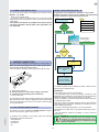
4.1 POWER CABLE INSTALLATION
WATER CHARACTERISTICS INLET "B"
To guarantee correct appliance operation, several water
treatment systems may have to be installed. For that purpose,
see the instructions of the following Flow Chart :
To connect the power cable to the appliance, proceed as follows:
Model 6 - 10 - 20 GN
• Remove the left side panel.
• Connect the cable to the terminal block as shown in the wiring
diagram attached to the appliance, and secure it with the special
cable gland.
The manufacturer declines any liability if the current national
and local regulations and possible safety regulations are
not respected.
Water inlet “B”
5° f
=
50 ppm Ca CO3
2.81° d
3.51° l
Chloride
appraisal
< 10 ppm
1.00 moz / cuB CaCO3
> 10 ppm
0.50 mmol / l
See instructions of
graph page 459
WITH FILTER
(ORSMOTIZER or NANOFILTER)
NO ACTION REQUIRED
Hardness
appraisal
< 5° f
> 5° f
A water softener must be
5. WATER CONNECTION
installed *
(See the installation diagrams at the beginning of this handbook)
When connecting the appliance to the water system with
hoses they must be new and not used.
The oven has two separate water supply inlets ("B" and "N").
Water system ready
to be connected to
oven
Make sure the dynamic
pressure is between
150 and 450 kPa
(1.5-4.5 bar / 22-65 psi)
I
N
B
* If deemed suitable by the installer, the water softener can be
replaced with a NANOFILTER.
C
C - Water drain manifold
B - Steam generator or boiler water supply connection
N - Condensate and Cleaning water connection
I - Power cable entry
ATTENTION:
conductivity above 50 μS/cm is necessary.
- The periodical check of filter functionality, according to that
indicated by the manufacturer, is important to avoid compromising
appliance operation and to prevent the risk of corrosion.
- For good operation of the water softeners and filters make sure
to regularly service them.
The feed pipes of both inlets must be provided with a mechanical
filter and shutoff valve. Before installing the filters it is advisable
to allow a certain amount of water to run in order to clear the pipe
of any solid particles.
Note: The softener (Automatic Water Softener) with automatic
regeneration has a kit (Resin Sterilizer) for sterilization of the
resins (additional request).
5.1 SUPPLY WATER CHARACTERISTICS
- To prevent damaging the appliance, at every periodical
regeneration do a filter wash cycle without introducing water in
the oven.
- The manufacturer declines any liability in case of incorrect
maintenance.
5954 962
007 00
01
5958
The appliance must be supplied with drinking water having the
specific characteristics given in this section.
Attention:
Dispensers of substances for preventing scale in
the pipes (e.g. polyphosphate dispensers) must
not be used because they can compromise correct
appliance operation.
To appraise the suitability of the supply water the following
characteristics must be measured:
- Total Hardness
- Conductivity
- Chloride Cl- pH
43
GB
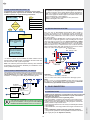
WATER CHARACTERISTICS INLET "N"
For UK and COMMONWEALTH only:
This appliance is designated as a forced draught burner, thereIn
To guarantee correct appliance operation, several water
accordance with "the water supply (Water Fittings) Regulations
treatment systems may have to be installed. For that purpose, 1999", it is mandatory that this appliance when installed to the
see the instructions of the following Flow Chart :
mains water supply has fitted an approved "double check valve"
connected upstream of the appliance.
5° f =
Failure to comply with these regulations may lead to the
appliance being disconnected.
50 ppm Ca CO3
Water inlet “N”
2.81° d
3.51° l
Hardness
appraisal
< 5° f
1.00 moz / cuB CaCO3
0.50 mmol / l
5.2 WATER DRAINING SYSTEM
> 5° f
The oven has an AIR-BREAK anti-backflow device inside to
prevent any backflow from the drainage system entering the
internal pipes and the oven compartment. This allows the drain
pipe to be connected directly to the mains system or discharging
into a floor grate.
The drain pipe (rigid or flexible type) can be run to the side or back
if the oven is not placed against a wall, excluding the front part
with rack support structure. It must not be more than 1 metre
long, with inside diameter not less than that of the oven discharge
pipe (1" 1/4), and must withstand temperatures of at least 100°C.
Make sure there are no constrictions in hoses or elbows in metal
pipes, along the entire drain path. Avoid horizontal sections where
water can collect and stagnate (min. slope 5%).
C - Oven drain
C1 - Safety outlet
A water softener must be
installed *
Water system ready
to be connected to
oven
Make sure the dynamic
pressure is between
150 and 450 kPa
(1.5-4.5 bar / 22-65 psi)
* If deemed suitable by the installer, the water softener can be
replaced with a NANOFILTER, provided the minimum water flow
rate for the oven wash cycle is respected.
Note: The softener (Automatic Water Softener) with automatic
regeneration has a kit (Resin Sterilizer) for sterilization of the
resins (additional request).
CHECK SUPPLY PRESSURE INPUT "B" AND "N"
The pressure measured upstream of the oven (and downstream of
any WATER FILTRATION SYSTEMS installed) must be between
150 and 450 kPa (1.5 - 4.5 bar / 22-65 psi)
measured in dynamic
conditions, i.e. during the boiler filling and washing phase.
N
150-400 kPa
(1,5-4,5 bar / 22-65 psi)
H2O
H 2O
WATER
FILTRATION
SYSTEM
6. GAS CONNECTION
150-400 kPa
(1,5-4,5 bar / 22-65 psi)
6.1 INSTRUCTIONS
WATER
FILTRATION
SYSTEM
• Make sure the appliance is arranged for the type of gas to be
used, otherwise follow the instructions in par
. 7 "Conversion
to another type of gas".
• The gas connection union is painted yellow.
• Before installing, consult the gas company to check the compatibility between the supply capacity and foreseen consumption.
• Before connecting the appliance to the gas pipes, remove the
plastic protection cap from the union.
• Fit a rapid gas shutoff cock in an easily accessible place ahead
of the appliance.
• After installation, use soapy water to check gas connections for
leaks.
• The combustion aeration capacity cannot be modif ed.
• Always check operation in case of possible connection to another
type of gas (see par. 8 "Operation Check").
Attention (water inlet N)
If the feed pipes supplied with the appliance are not long
enough for installation, use longer ones with internal
diameter of at least ø 20 mmand without union elbows.
44
5954 007 01
B
Attention:
- Do not obstruct the safety outlet C1.
- Do not connect the safety outlet C1 to the drainage system.
Note:
If water comes out of the AIR-BREAK (safety outlet C1) it means
the drain C is blocked. Elimination of the obstruction should be
carried out by specialised technical personnel.
GB
6.2 NOMINAL HEAT OUTPUT
The diameter of the reducer's middle hole is given in mm.
• Undo the 2 nuts "P" securing plate "L" to burner "H".
For data regarding the nominal heat output refer to "Technical
• Unscrew the 4 nuts "F" securing blower "G" to burner "H".
Data" Table 1.
• Replace plate "L" (including the 2 seals "M") with the one for
This parameter is determined by the gas supply pressure and the
gas G30 and G31 (LPG)
diameter of the gas valve diaphragm (nozzle).
• Insert the 2 pins "L1" of plate "L" in the 2 slots "H1" and retighten
Appliance nominal heat output must always be checked (by
the 2 nuts "P" (with respective washer).
the authorised installer or by the gas company) in case of new
• Retighten the 4 nuts "F" (with respective washer).
installations and conversion to a different gas type or following
all maintenance work.
Any change to the nominal heat output is strictly prohibited.
6.3 SUPPLY PRESSURE CHECK
(Fig. 2a)
The supply pressure must be measured ahead of the gas control
valve with the appliance operating (after conversion in case of a
different type of gas), using a pressure gauge with minimum
resolution of 0.1 mbar and proceeding as follows:
1) Remove the left side to access the gas valve;
2) Loosen screw "C" of the gas valve pressure point and connect
the pressure gauge tube to it;
3) Open the gas shutoff cock;
4) Start a combi cooking cycle(see "Operating instructions")
so that all the burners can be lit;
5) Check that the pressure reading is within the values given in
the following table:
7.3 REPLACING THE GAS VALVE
DIAPHRAGM (NOZZLE)
• Unscrew the hex nut of union "A" with the respective seal "A1"
and replace diaphragm "B" (nozzle) with one suitable for the type
of gas used by relevant burner (convector or steam generator)
and the oven model purchased (see Table 2 - following pages).
The diaphragm (nozzle) diameter, shown in hundredths of mm,
is stamped on the body (e.g. ø3.5 mm, stamping: 350)
• Retighten hex nut "A" with the respective seal "A1".
• Repeat the above operations for the other valves (if present)
and proceed with the instructions in the next paragraph.
GAS TYPE PRESSURE (MBAR)
Nom.
Natural gas G20
LPG G30/G31
(Fig. 2a)
Min. Max.
for Japan
p
Natural gas 13A
LPG
PRESSURE
Natural gas
L. P. G.
(KPa)
for AUSTRALIA
7.3.1 CHANGING PARAMETERS
• Change the electronic card parameters relevant to the burner
blower control as indicated in the service manual (not supplied).
The appliance will not function with different values.
Inform the gas company;
6) After measuring the supply pressure, stop the cooking cycle
and close the gas shutoff cock.
7) Disconnect the pressure gauge and carefully tighten screw "C";
8) Close the appliance.
7.4 GAS VALVE ADJUSTMENT
(Fig. 2a)
Note: The adjustments given below must only be made by a
technician authorised by the manufacturer.
To adjust the pressure (negative) of the gas valve, adapting it to
a type of gas different from that for which it is arranged, proceed
as follows:
7. CONVERSION TO ANOTHER TYPE OF GAS
• Loosen the screw "D" relevant to the gas valve pressure point
and connect a pressure gauge with minimum resolution of
1 Pa to it;
• Remove adjustment screw cap "E1".
• Light the burner and select on the control panel a HOT AIR
cooking cycle for the convector and STEAM for the steam generator (see "Operating instructions").
• 1 minute after lighting the burner, use a suitable tool to turn
screw "E" of the valve, adjusting the pressure (negative) until
the pressure gauge reading matches the value shown in TABLE
2 (following pages) for the burner in question. Wait a few minutes
and (if the value has changed) adjust screw "E" again.
• After adjusting, refit cap "E1" and seal it with red paint, taking
care not to clog the vent holes in the valve.
• Turn off the burner.
• Repeat the above procedure for the other valves (if present).
Attention: The appliance is factory set for a type of
gas, as specified on the stickers on the appliance and
packing. To convert the appliance to anther type of
gas, carefully follow the instructions given below, using
the diaphragms (nozzles) contained in the bag supplied with
the appliance.
7.1 ACCESSING COMPONENTS
5954 962
007 00
01
5958
• Remove the appliance left side panel.
7.2 REPLACING THE
BURNER-BLOWER REDUCER (PLATE)
(Fig. 2b)
Attention:
After conversion, ref t the oven outer panels.
The reducer (plate) must be replaced for gas G30 and G31 (LPG)
only in some models as indicated in TABLE 2 (following pages).
45
GB
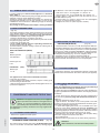
7.5 TABLE 2: NOZZLES AND ADJUSTMENTS / GAS TYPES
2a - 2b
FIGURE
6 GN1/1
n° of GRIDS
CONVECTOR °
BOILER **
°
REFERENCE
10 GN1/1
°
**
10 GN2/1
°
**
20 GN1/1
°
**
20 GN2/1
°
**
**
ø
#
ø
#
ø
#
ø
#
ø
#
ø
#
ø
#
ø
#
ø
#
ø
#
Diaphragm
G30
5,25
525
4,75
475
5,5
550
5,8
580
5,8
580
5,8
580
5,5
550
5,8
580
5,8
580
6
600
(nozzle)
G31 L.P.G.
Propane Gas (AU)
5,5
550
5
500
5,7
570
5,7
570
6,25
625
6,15
615
5,7
570
6,15
615
6,25
625
6,25
625
gas valve
G20 - 13A
Natural Gas (AU)
6
600
6
600
7
700
7
700
7,8
780
7,5
750
7
700
7,5
750
7,8
780
7,5
750
Heading 7.3
G25
natural gas
6,75
675
6,75
675
8
800
8,5
850
8,5
850
9
900
8
800
9
900
9,25
925
9
900
REPLACING °°
G30
Propane Gas
12
burner-blower
G31 L.P.G.
Propane Gas (AU)
reducer (plate)
Heading 7.2
12
18
18 °°
18 °°
18 °°
18
18 °°
18 °°
21
12
12
18
21(AU)
18 °°
18 °°
18 °°
18
18 °°
18 °°
21
G20 - 13A
Natural Gas (AU)
12
12
18
21(AU)
21
21
21
18
21
21
21
G25
natural gas
12
12
18
21
21
21
18
21
21
21
R
G (AU)
R
G (AU)
Ventilator *
G30/G31 L.P.G.
Propane Gas (AU)
F
F
(ring)
G20 - 13A
Natural Gas (AU)
F
F
burner
G25
natural gas
F
F
Adjustment
G30
0 / -10
0
0
0 / -10
0
0
8 (AU)
0 / -10
-10 (AU)
0
-15 (AU)
pressure
(negative)
G31 L.P.G.
Propane Gas (AU)
gas valve (Pa)
G20 - 13A
Natural Gas (AU)
Heading 7.4
G25
natural gas
0 / -10
0
0 / -10
0
0 / -10
R
0
0
G
G
G
R
G
G
G
G
G
G
R
G
G
G
G
G
G
R
G
G
G
0
0 / -10
0
0 / -10
0 / -20
0
0
0
0
0
0 / -10
0 / -10
0
0 / -10
0
0
0 / -10
0
0
^ 0/-20
v 0/-10
0
0
^
v
0
-10
0
0
F (Fuchsia)
R (Red)
G (Green)
Ø
= diameter (mm)
#
= stamping
^ (up) = upper burner gas valve
v (down)= lower burner gas valve
* The aerator (coloured ring) "N" (fig. 2b) of the burner blower must not be replaced; the colours given in the table are only a guide.
(AU) = AUSTRALIA
GAS VALVE
(CONVECTOR / STEAM GENERATOR)
- Replacing diaphragm "B"
- Screw "E" adjustment
BURNER BLOWER
(CONVECTOR)
- Replacing plate "L" for gas G30 and G31 (LPG)
H
A1
A
L
P
B
F
G
E1
E
D
H1
L1
neywell_sigma
N
M
2a
46
2b
5954 007 01
C
GB
7.6 GAS TYPE STICKER
The burner goes out(the message "burn" appears on the display
TM, see "Operating instructions" chap. 5).
Possible causes:
- Power supply polarity (Phase/Neutral) inverted.
- The oven electrical system is "Phase/Phase" type. In this case
install the special "Transformer Kit" available from the manufacturer.
- Faulty gas valve.
- Flame detection electrode incorrectly positioned or disconnected.
- Burner fan unit damaged (shutdown situation).
- Flame control device damaged.
- High room humidity (condensation): air the room.
After the conversion to a different type of gas, apply the sticker for
the new gas on the oven in place of the existing one. The sticker
in included in the bag supplied.
8. SAFETY DEVICE
The appliance is equipped with the following safety devices:
- Fuses, see the wiring diagram, located behind the control panel.
For replacement, unscrew the cap and replace the damaged
component with another one having the same rating; this value
is given on the label located in the same place.
- Compartment manual-reset safety thermostat located behind
the control panel; it shuts off the gas supply to the convector burner.
Incorrect oven compartment temperature thermostatting .
Possible causes:
- Electronic control panel faulty.
- Oven compartment temperature probe dirty, faulty or disconnected, see configuration error EPt1 (see "Operating instructions"
chap. 5).
- Steam generator manual-reset safety thermostat located
behind the control panel; it shuts off the gas supply to the generator burner.
The oven fails to switch on. Possible causes:
- Electronic control panel damaged.
- Fuse F2 blown due to damaged auxiliary circuit components.
Resetting operations must be carried out by specialised technical
personnel after eliminating the causes of interruption.
Oven compartment lamps damaged
ATTENTION: Switch the appliance off before replacing oven
compartment lamps.
- Automatic-reset thermal device inside the fan, which is activated if the fan overheats, protecting unit operation; it cuts off the
electrical power to the appliance.
12. POSITIONING OF MAIN COMPONENTS
9. OPERATION CHECK
(Any operation inside the appliance must only be carried out
by an installer authorised by the Manufacturer).
- Switch the appliance on, as described in the section "Operating
instructions";
- Explain appliance operation, routine maintenance and cleaning
operations to the user, with the help of the instruction handbook.
Open the control panel to access the following components:
- Electronic boards.
- Compartment temperature limiter thermostat.
- Fuses.
- Door safety microswitch.
- Compartment vent shutter control gear motor.
Attention:
- During operation, pay
attention to the hot areas of the exterior surface.
- Do not place objects on the outlets located at the
top of the appliance.
Remove the appliance left side panel to access to all the other
components.
- With oven hot, check the correct working of the door closing
mechanism. If necessary, adjust closing by adjusting the position
of the catch.
10. MAINTENANCE
The components requiring routine maintenance are accessible
by opening the control panel, and left and rear panels.
11. BRIEF TROUBLESHOOTING GUIDE
5954 962
007 00
01
5958
Even with correct use of the appliance, malfunctions can occur.
The burner fails to light(the message "burn" appears on display
TM, see "Operating instructions" chap. 5).
Possible causes:
- The ignition electrode is incorrectly positioned or the insulation
is faulty.
- The ignition/flame control device is damaged.
- The ignition electrode high tension lead is broken or leaking.
- Insufficient gas pressure.
- Faulty gas valve.
- Burner fan unit damaged, insufficient air pressure in combustion
chamber.
- The electronic control panel is damaged.
- Blown fuse, see wiring diagram.
- Compartment temperature probe damaged (configuration error
EPt1 - see "Operating instructions" chap. 5).
- Temperature limiter activation.
- High room humidity (condensation): air the room.
47
GB
III. OPERATING INSTRUCTIONS
Before starting the appliance, carefully read this handbook. The
instructions and information given in it are important for correct
and optimum oven use. If required, further details regarding its
characteristics and cooking performance can be obtained from
the dealer.
• To avoid obstructing the fume and steam discharge pipes, do
not place pans or utensils of any kind on the oven.
• Do not place objects (e.g. pans) under the bottom of the oven,
so as not to obstruct any cooling air inlet or outlet holes.
• Have the appliance fully checked periodically (at least once a
year). For that purpose, it is advisable to stipulate a maintenance
contract.
• The core probe is a precision component. Absolutely avoid
impacts, forcing when inserting, and pulling of the flexible cable
(in particular when using the trolley-mounted structures). The
warranty does not cover the replacement of core probes
damaged by improper use.
• In the combi cooking cycle it is advisable not to exceed temperatures of 200-210°C. Higher values can reduce the efficiency
of the compartment seals.
• When arranging food inside the oven compartment, keep a
space of at least 40mm between trays, to ensure better circulation of hot air.
• If the oven is installed near appliances that produce greasy
fumes (e.g. fryer), make sure to use the air filter (not supplied),
to be placed under the control panel, to protect the internal
electronic components.
• During preheating of oven 20 GN 1/1 or 2/1, insert the trolley
(without food) or the special accessory (not supplied) to close
the bottom opening between the compartment and door. This
prevents steam from coming out and into the control panel with
consequent damage to the electronic board.
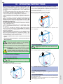
MODELS WITH DOUBLE OPENING SYSTEM (on request)
The oven has a double opening system to prevent being exposed
to steam when opening the door completely; therefore carry out
the following operations:
a) Turn the door handle all the way clockwise.
The door opens a little, hooking on the stop.
The cooking cycle is stopped, if in progress.
1
b) Turn the handle all the way anticlockwise to open the oven
door completely.
• Do not salt food inside the oven, in particular with humid
cycles.
• Do not place flammable liquids (e.g. spirits) inside the oven
during operation.
2
The maximum height at which the trays are placed
in the oven must not exceed 1.6 m. This applies if
installed according to the instructions and using
original accessories (except for stacked ovens).
In case of stacked ovens or in any other case when the above
distance is exceeded, the following sticker (supplied) must be
placed on the front of the oven in a visible position at a height
of 1.6 m from the floor.
ATTENTION: To avoid burns, do not use recipients
containing liquids (or products that become liquid with cooking) on levels that are not easily
visible. This is to prevent spilling during handling.
1.2 20-RACK MODEL
Attention! Risk of burns.
Always open the door with caution when the oven
is hot.
a) Turn the handle anticlockwise 90° to open the door completely.
The cooking program is stopped, if in progress.
1. OVEN DOOR OPENING
1.1 6 AND 10-RACK MODEL
Attention! Risk of burns.
Always open the door with caution when the oven
is hot.
a) Turn the door handle all the way in either direction (indifferently)
to fully open the oven door.
The cooking cycle is stopped, if in progress.
1
2. OVEN DOOR CLOSING
2.1 6 AND 10-RACK MODELS
Closing is obtained by pressing the door against the oven enough
to lock it.
a) Turn the door handle all the way anticlockwise and bring the
door against the oven.
b) Keeping the door pressed against the oven, bring the handle
to the upright position and lock it.
1
48
5954 007 01
2.2 20-RACK MODELS
GB
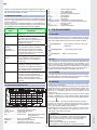
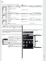
3. DESCRIPTION OF CONTROL PANEL ......
M
Humidity setting and adjustment :
for activating or excluding the humidity
or adjusting the required level in the
Hot Air Cycle.
The control panel has the following controls:
ON/OFF oven switch.
_______________
Hot air cycle with compartment vent open
:
for very dry cooking, allowing the removal of
humidity when necessary (max. temperature
300°C).
Hot air cycle with adjustable compartment
vent: for cooking with humidity adjustable from
1 to 99 %, allowing the removal of humidity
when the set value is exceeded.
____________
Touch screen
with direct selection of functions
by simply touching the
required symbol (icon), to activatethe corresponding ovenfunctions.
Hot air cycle with compartment vent closed
:
for cooking with high humidity. (Default setting)
Digital thermostat for
control of compartment
temperature.
USB port
________________
Data input and output
Timer for control of
cooking time.
The letter S next to the
number means short cooking cycle; see symbol
MM:SS.
or
Digital thermometer/
thermostat for control
of product core temperature.
3.2 MAIN FUNCTIONS AND SYMBOLS
MANUAL
Hot air cycle: for roasting and gratinating with max.
temperature 300°C.
Cooking with ECO-DELTA: for cooking large pieces
of food (at least 5kg, e.g. whole turkey, leg of pork, etc.).
In this cooking mode a temperature setting of between
1°C and 120°C is selected.
In this case, cooking is moderate and long, since
the COMPARTMENT temperature is automatically
adjusted according to the temperature inside the food
(CORE PROBE), maintaining a constant difference
(ECO-DELTA) between them, from start to end of
cooking.
The ECO-DELTA function is only possible with the
core probe inserted.
Combi cycle: superheated steam. The steam generator and compartment heaters are used at the same
time to keep foods tender (max. temperature 250°C).
5954 962
007 00
01
5958
Steam cycle: ideal for boiling (operating temperature automatically fixed at 100°C).
Low temperature steam can be set for gentle
cooking, vacuum packed foods and for defrosting
(temperature from 25°C to 99°); superheated steam
(temperature from 101° to 130°C).
Example:
COOKING:
ECO-DELTA
=
CORE PROBE =
COMPARTMENT =
Electronic humidity adjustment: for
adjusting the required humidity level in
the Combi Cycle.
49
START
80°... 80...80...
10°... 11...12...
90°... 91...92...
......
80...
40...
120...
END
80°C (set)
60°C (set)
140°C (result)
GB
Fast compartment cooling: useful for going from
one type of cooking to another at lower temperature;
it enables fan rotation and automatic injection of
water (TS < 180°C) even with the door open.
UTILITIES
Low speed cycle (fan): for gentle baking,
such as light patisserie. Combinable with all
cycles.
Attention! Risk of burns.
Always open the door with caution when
the oven is hot.
Pulsed speed cycle (fan): for low temperature cooking, ideal for maintaining cooked
products, dehydrating or drying for vegetables
or finishing food. Combinable with all cycles.
Continuous cooking: the cooking time is endless,
therefore it is necessary to press STOP when the
food is cooked.
Normal speed cycle (fan):for normal cooking.
Ideal for roasting, gratinating and classic
cooking. Combinable with all cycles. (Default
setting)
MM:MINUTES and SS:SECONDS for short cooking
cycles. Converts minutes into seconds and the letter S
appears next to the number in the bar as an indicator
Manual injection of water in compartment:
for instantly increasing the humidity level
during a cooking cycle. Use the + and - buttons
to adjust the injection duration in seconds (10
s intervals).
INFORMATION - NOTES - WARNINGS
Information area
Area displaying current
Status, Error, Warning
and Utility information.
Low power cycle (heating):for gentle baking, such
as light patisserie. Combinable with all cycles.
FSC-STANDARD risk cooking: for foods having a
low contamination level.
Warning light signalling oven door open.
FSC-HIGH risk cooking: for foods having a high
contamination level.
Scale indicator: when this light comes on, the steam
generator must be descaled. Follow the instructions
given in par. 6.1.
FSC- The FOODSAFE CONTROL had positive results,
cooking occurred in safe conditions
Steam generator status light:
Save Program
- generator in f lling phase or no water. Make sure
water reaches the oven!
Programmed Start: allows the cooking cycle to be
started later by setting the required time.
- generator in preheating phase.
- generator ready (indicator light off).
Multitimer: for setting cooking of foods at the same
temperature but at different times (max. 14).
burner off
MULTIPHASE
Cooking with phases in sequence : for setting
cooking programs with several phases in automatic
sequence (max. 15 phases).
Error
Attention
Active pause phase
Add pause phase: by entering a time value in this
mode it is possible to delay the start of cooking programs or include a pause between two cycles (e.g.
proving).
Queries
50
5954 007 01
Information
GB
Active Maintaining Cycle phase.
Go back to previous page
Add Maintaining Cycle (70°C):for slow and prolonged
cooking, typically for meat (large cuts). Activated at the
end of cooking.
Combinable with all cycles.
Cancel space (Backspace)
Find Program
Custom
SPECIAL CYCLES
Regeneration cycle: produces the optimum humidity
for fast heating of products to be regenerated. Ideal
cycle for heating and regenerating complete menus,
single or multiple portions (e.g. banqueting) in pans or
single dishes. Also ideal for regenerating stale bread.
Upload data in oven from USB port
Download data from oven on USB port
Low Temperature: low temperature cooking cycle to
obtain tender and evenly cooked food.
Restore oven conf guration to default values (Reset)
Proving: Ideal cycle for raising baking products, buns,
pizzas and various doughs.
Drawer
The drawer is an expansion located inside several environments of
the menu and contains options that are useful in some functions.
Technical assistance
VARIOUS AND COMMON FUNCTIONS
Manual draining of steam generator water: press
the button to drain water from the steam generator.
(See 6.1 STEAM GENERATOR PERIODICAL
MAINTENANCE)
Attention! In order to prevent excessive
scaling in the steam generator , make
sure to:
respect the parameters regarding the water
supply – see installation;
always drain the generator at the end of each
day.
Compartment preheating: indicates that the oven is
preheating the compartment (please wait).
This phase can be skipped in MANUAL mode but not
in AUTOMATIC mode.
SKIP PHASE:the next foreseen phase can be skipped
for particular types of cooking.
- Compartment preheating (excluding AUTOMATIC)
- Low temperature phases (PREHEAT, SEARING)
5954 962
007 00
01
5958
Skip PHASES in Multiphase: one or more phases
can be skipped during cooking with Multiphase.
Conf rm
51
GB
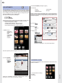
OVEN USE
4. CONTROL PANEL USE
4.2 SWITCHING THE OVEN OFF
To switch the oven off, press the button O (O - I) of the following
switch:
Foreword:
When selecting certain functions, the initial status is restored if
no button is pressed within 15 seconds (approx.).
O°I
4.1 SWITCHING THE OVEN ON
Before using the oven, make sure:
- the external electric safety switch is on;
- the water shutoff cocks are open;
- the oven outlets are not blocked.
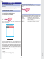
4.3 SELECTING CONTROLS (AREAS)
The controls are mainly divided into 5 different management areas
for the various functions. These are selected from the CONTROLS
MENU in the drop-down menu of the first line of MANUAL mode.
Switch the oven on by pressing the button I (O - I) of the following
switch:
Manual
Programs
O°I
Automatic
Cleaning
Settings
the start screen will appear, during which the electronic board
performs several checks.
= manual cooking mode (conventional).
= use of existing programs (or recipes) and
storing of new ones.
= automatic cooking system.
= cleaning programs for oven compartment.
= variation and configuration of functions.
Touch screen
Touch the symbols on the "touch screen" to select the oven
functions, setting and modifying the relevant values. It is also
arranged with a basic functions menu to simplify use, and can be
customised as required by adding or removing some functions.
The "touch screen" has a similar use to that of a cell phone and
computer, with drop-down menu and keypad for entering values.
In some cases, by touching the required symbol a screen relevant
to the symbol appears, and in others only the function is selected.
TOUCH the required part of the Display to perform any
operation, such as:
- select
- conf rm
5954 007 01
- change screen (or Display page)
52
GB
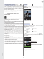
In this way a cooking cycle has been set; now, just close the door
and touch START to start the Cycle.
The PREHEATING stage starts, after which the message "LOAD"
appears, indicating to place food in the oven; close the door to
start cooking.
In case of AUTOMATIC START, just close the door to automatically start the cycle.
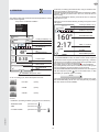
4.4 MANUAL
After SWITCHING THE OVEN ON the following MANUAL cooking
mode screen appears:
After about 10 seconds the following Cooking in Progress screen
will appear:
Drop-down "CONTROLS MENU":
Manual
Programs
Automatic
Cleaning
Settings
HUMIDITY in progress
160°
2:17
Cooking PHASES (1 of 1)
1 of 1
Set COMBI cycle
Cooking CYCLES
50%
Set HUMIDITY
0:30
48°
0:30
START
2:30
Set
TEMPERATURE
Set TEMPERATURE
TIME in progress
set TIME
HALF SPEED in progress
(example)
* In PROGRAMMED mode, the word "Combi" will be replaced
by the name of the Program or Recipe in progress (e.g. Chicken)
Current TIME
Set TIME
This figure (for information) shows nearly all the possible cases;
but only those concerned are presented.
Touch this screen to return to the MANUAL control Settings.
Any setting already made can be modified and the Cooking Cycle
can be stopped by touching STOP for a few seconds.
The SKIP COMPARTMENT PREHEATING function also appears
with the respective symbol
next to the STOP button, to skip
preheating for particular types of cooking.
Start CYCLE
INFORMATION
AREA
"DRAWER" drop-down menu
with Utilities in several items of the CONTROLS MENU
STOP
To set a cooking cycle, select the required CYCLE:
HOT AIR
(touch)
COMBI
(touch)
STEAM
(touch)
The previous description regarded setting a cooking Cycle. Now,
this will enable setting others in a more complex way, by adding
the other functions made available.
and set:
- HUMIDITY (excluding STEAM cycle) (touch CYCLE button)
- TEMPERATURE
(touch the bar
)
- TIME
(touch the bar
)
(touch the bar
and then
)
5954 962
007 00
01
5958
or CORE PROBE
COMBI cycle * in progress
Combi
Manual
Phase
Cooking PHASE (2 of 3)
Phase 2/3
53
GB
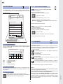
The functions in MANUAL Cooking mode are as follows:
cycle HOT AIR
HUMIDITY
---->
---->
---->
adjustable
compartment vent open
compartment vent closed
Eco Delta *
x (vent
x
x
-
---->
---->
endless
MM:SS (short cooking cycles)
)
TEMPERATURE
TIME
CORE PROBE
x
x (from 20° to 120°)
x (max. 8 hours)
-
x (from 10° to 99°)
-
-
x
-
-
max. 59 min. and 59 sec. -
cycle COMBI
HUMIDITY
TEMPERATURE
TIME
CORE PROBE
---->
adjustable
Eco Delta *
x (%)
-
x
x (from 20° to 120°)
x (max. 8 hours) x (from 10° to 99°)
-
---->
---->
endless
MM:SS (short cooking cycles) -
-
x
max. 59 min. and 59 sec. -
cycle STEAM
HUMIDITY
TEMPERATURE
TIME
---->
adjustable
Eco Delta *
-
x
x (from 20° to 120°)
x (max. 8 hours) x (from 10° to 99°)
-
---->
---->
endless
MM:SS (short cooking cycles) -
-
x
max. 59 min. and 59 sec. -
CORE PROBE
Eco Delta: on setting the temperature range, a small
*
triangle will appear as a reference next to the value; also, the
time bar goes to that of the core probe
for the relevant setting.
E.g. In the HOT AIR cycle, as indicated in the previous table, it is
possible to set the Humidity, Temperature, Time or Core Probe,
and Temperature with Eco Delta, compartment Cooling, endless
Time for continuous Cooking (conventional cooking) and Short
Cooking Cycles (MM:SS).
To add more functions, there are the UTILITIES situated in the
DRAWER and selected as cooking cycle variables.
To set the data of the various functions, a keypad like the following
is used:
DRAWER open
To zero-set the value just entered, touch the
0 on the keypad.
If a function (e.g. Eco Delta
) has been
set on the keypad, to cancel it just touch the
same button again.
To return to the initial setting, select another
cycle and return to the same.
UTILITIES
Cooling: it is possible to set an oven
compartment cooling temperature to be
reached, which will be indicated with the
corresponding symbol on the cooking in
progress screen.
Compartment cooling therefore occurs
manually and is done outside the cooking
cycle.
5954 007 01
INFORMATION
real data
54
GB
UTILITIES (see page 47)
cycle
HOT AIR
COMBI STEAM
x
x
x
Injection of water in compartment x (from 10sec. to 120sec.) -
-
Reduced power
x
x
x
Programmed Start
x
x
x
Fan speed *
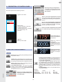
1
phase number
50%
160°
0:30
combi cycle
humidity
temperature (C°)
cooking phase time (0 hours : 30 minutes)
Also, one or more phases can be skipped during cooking; press
next to phase 3 (ex. in figure) to go to this.
the symbol
3
FSC (Food Safe Control) x
x
x
Store programs
x
x
x
The Multiphase also has special phases, such as:
- Pause
for setting a pause between cooking cycles.
- Maintaining cycle
with the possibility of setting a food temperature that is kept constant for an infinite time 8
*
The default speed is the maximum and never appears in
the information field, whereas the others will appear if selected
(half or pulsed).
INFORMATION (real data)
23%
humidity
175°
compartment temperature (C°)
28°
core probe temperature (C°)
01:58
clock (1 hour : 58 minutes)
50%
225° 0:45
4.4.2 MULTITIMER
With the MultiTimer system it is possible to set a different time for
each recipe (chicken, potatoes, etc.) or for each pan placed on
the various levels, e.g. starting from level 1 at the top and going
down to 2, 3, etc.
This function also allows the oven to be used with an "à la carte"
menu, where the food can be placed in the oven at the required time.
To set the MultiTimer, proceed as follows:
1) open the drawer in Manual mode and press the relevant button
Important
When the oven is switched on after several hours of inactivity, wait
20 seconds (the time necessary for stabilisation of the LAMBDA
probe) for a correct HUMIDITY reading.
MultiTimer button
Then press the following buttons:
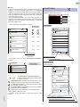
4.4.1 MULTIPHASE
Food can be cooked with different modes during its cycle and
therefore in different phases.
The oven enables programs consisting of several sequential phases (up to a max. of 15 phases). During cooking, going from one
phase to the next occurs automatically, until automatic stopping
of the program with completion of the last set phase.
A cycle with several phases is set by carrying out the following
operations:
1) switch the oven on;
2) Set for PHASE 1:
- cooking mode (humidity if necessary);
- compartment temperature;
- cooking time (or alternatively the core probe temperature).
3) Press the "Phase" button and then the "Add new phase" button.
4) For PHASE 2 and following, set as per PHASE 1.
When there are several phases, these will be listed, giving the
relevant settings (an arrow will scroll the next ones which are
not displayed).
2) START
cycle start for setting the Multitimer
START
3) MultiTimer
to access the setting of times.
Manual
Multitimer
Timer 1:
Timer 3:
MultiTimer -------->
Timer 5:
Timer 7:
Timer 9:
Timer 11:
Timer 13:
-- : --- : --
-- : --
-- : --- : --
-- : --
-- : --
Timer 2:
Timer 4:
Timer 6:
Timer 8:
Timer 10:
Timer 12:
Timer 14:
-- : --- : --
-- : --
-- : --- : --
-- : --
-- : --
Manual
Phase
50% 160° 0:30
2
3
120° 1:15
50%
225° 0:45
4
0:15
160°
48°
0:30
Add New Phase
5954 962
007 00
01
5958
0:30
Add Pause
4) Timer1
11of
of12
1
1
Skip phase basket
5) --:--
Utilities (in drawer)
and enter the recipe name (chicken, potatoes,
etc).
and enter the time with the keypad.
For Timer2 and following, set as per Timer1.
Pause phase
To start the cooking cycle, open the oven door, load the food and
close the door.
The MultiTimer will start the countdown with the position having
the shortest time setting.
Scroll list arrow
Add phase button
At the end of each set cooking time the oven will sound a beep
to indicate the type of food cooked. Open the door and remove
the ready to serve product.
Auxiliary functions
Save Program
The figure shows phase 1 with the following settings:
55
GB
4.4.3 ECODELTA
4.4.5 FSC (Food Safe Control)
The ECO DELTA function enables cooking without harming the food with high temperatures; this ensures more gentle
and more even cooking, with less weight loss.
This is an advanced cooking method, where the oven compartment
temperature varies according to the core temperature
of the food.
The operator can select a Delta value of between 20°C and
120°C; it is advisable to set a value between 20°C and 70°C, and
a value between 10°C and 99°C for the Core Probe. The oven
compartment temperature is automatically adjusted in order to
always be higher than that in the core of the product.
The FOOD SAFE CONTROL (FSC) is a device enabling the
microbiological SAFE condition
of the food to be controlled during cooking.
Depending on the chosen food category (HIGH risk or
STANDARD risk), during cooking the FSC recognises the moment
when the food reaches an acceptable sanitisation level for its
SAFE consumption.
The cooking results can be shown on the DISPLAY.
The process requires strict compliance with proper food processing
practices according to the rules of hygiene,
before and after cooking.
Cooking using the FSC does not sanitise bad or deteriorated
food, which remains so even after cooking.
TEMPERATURE
To use the FSC, set a cooking cycle as described above.
Always insert the CORE PROBE even with TIMED cooking cycles.
tpar
com t
n
e
m
C°
120
The FSC is composed of 2 categories:
e
cor
be
pro
70
FSC-STANDARD risk cooking: for foods having a
low contamination level. (e.g. whole pieces of beef)
Δ T (Eco Delta) = 50°C
FSC-HIGH risk cooking: for foods having a high
contamination level. (e.g. roulades of meat, mincemeat, poultry, pork, fish)
20
0
TIME
Set the HIGH or STANDARD risk category in the UTILITIES
drawer and press "START" to start.
The graph shows an example with a set Delta of 50°C where the
compartment temperature increases, keeping this difference of
50°C constant with respect to the core probe.
This type of cooking is slower than the conventional cooking
method but has the advantage of obtaining better product results
and quality.
This type of cooking is ideal for large pieces of meat.
In this way, cooking with the FSC starts; if the safe condition is
reached during cooking, a confirmation will appear next to the
FSC symbol:
F: 0.0
The Pasteurization factor F with value reached will also appear
(if set).
If, on the other hand, cooking does not end in a safe condition,
the FSC warns with a dialogue window and requests ending of
the cycle automatically or manually by the user.
At the end (in one way or the other), the following will appear:
4.4.4 INFORMATION AREA
0:30
0:30
FSC
FSC x
for positive result
for negative result
X
The information area is the zone above the drawer that displays
oven operation status with icons, subdivided into items.
The figure above gives (starting from the left) the following:
door open
error x
descaling,
boiler preheating
fan speed,
5954 007 01
reduced power
56
GB
4.3.6 CORE PROBE USE
4.3.7 END OF COOKING
(PRODUCT CORE TEMPERATURE CONTROL)
The core probe allows accurate control of the core temperature
of the product being cooked. This enables setting of the required
value (from 10°C to 99°C) and automatic stopping of cooking
when that value is reached.
Attention: The core probe is a precision component.
Absolutely avoid impacts, forcing when inserting, and
pulling of the flexible cable (in particular when using
the trolley-mounted structures). The warranty does
not cover the replacement of core probes damaged by improper use.
At the end of the set time, the cooking cycle automatically stops
and the oven buzzer sounds continuously.
The display shows the message:
COOKING FINISHED !
Several parameters such as the following are also displayed:
- total time
- FSC a bar with relevant result will appear if set.
Open the door and remove the product.
Attention! Risk of burns.
Always open the door with caution when the oven
is hot.
After selecting the time icon select that of the core probe and
press START to start the cycle.
- Wait until the compartment temperature field indicates reaching
of preheating (the message LOAD appears).
- Open the door and introduce the product to be cooked.
Attention! Risk of burns.
Always open the door with caution when the oven
is hot.
Notes:
- The buzzer can be stopped in advance by carrying out any
operation on the control panel or by opening the door.
The cooking cycled can be manually stopped by keeping
the STOP button pressed for a few seconds.
A cycle identical to that just completed can be repeated by
pressing the START button again.
1) Remove the core probe "A" from its seat "B" and insert it in
the product without forcing excessively, making sure the tip (the
sensitive part) is positioned near the centre of the product.
A
B
MULTIPOINT 6-sensor core probe
The oven is equipped with a MULTIPOINT core probe with 6
sensors along the entire stem, for correctly measuring the product
core temperature even if the tip is not completely in the centre.
- Close the door and press the START button.
2) Stopping the cycle. When the required product core temperature is reached the oven stops automatically and the elapsed
cooking cycle time is displayed.
3) Core probe mode deactivation . Set a cooking time on the
Timer
. This action automatically cuts out the core probe,
whereas it is the opposite when the time is set.
The core probe mode is also deactivated when the oven is
switched off.
5954 962
007 00
01
5958
Note:
With vacuum packed food products it is necessary to use the
special external core probe (accessory available on request), to
be connected to the USB socket. For its use, see the instructions
included with the accessory.
57
GB
3) Preset COOKING (example in figure)
4.5 AUTOMATIC
▼ Steamed
- Custom
- Cuttlefish
- Seafood salade
The AUTOMATIC control mode is used for automatic cooking,
by setting several simplified functions. This saves the operator
from having to know the cooking parameter values (temperature,
time, humidity) and makes the same type of cooking more equal.
- Codfish fillet
- Octopus
Select one of the preset COOKING cycles to access the following
example screen (Roast meat) where the cooking MODE parameters are shown with the preset (default) choices which can be
modified if required.
Select AUTOMATIC from the Main Menu.
The functions to be set are as follows:
1) food TYPE
2) cooking MODE
3) preset COOKING
Automatic
There are also several parameters (which differ according to the
cooking Mode used) to be confirmed or modified, such as :
- Form of food (whole or fillets)
- Cooking system (timed or with core probe)
- Food Browning level (low, medium, high)
- Food cooking level (rare, medium, well done)
Baked, Custom
Form of food
- Whole
- Fillets
Form
Whole
Browning Level
- Low
- Medium
- High
1) TYPE of food
Browning Level
Low
Medium
High
Cooking Level
Cooking Level
- Rare
- Medium (70°)
- Well Done
- Red meat
- Minced meat
- Poultry
- Fish
- Vegetables
- Side dishes
- Bakery
- Dessert
Fillets
70°
70°
70°
Rare
Medium
Well Done
START
keypad for adjusting the core probe temperature
Also the Special Cycles can appear on the same screen.
Automatic
Fish
2) Cooking MODE
(example)
- Baked
- Steamed
- Grilled
- Gratin
Baked
Steamed
4.3.9 SPECIAL CYCLES
Custom
Codfish fillet
Cuttlefish
Octopus
The special cycles appear on the AUTOMATIC mode main screen,
and are as follows:
Seafood salade
Grilled
Au gratin
- Low Temperature Cooking
- Proofing
- Reheating
There are completely automatic cooking Modes where no
parameter can be set (e.g. Red Meat \ Steam).
58
5954 007 01
In tomato sauce
GB
LOW TEMPERATURE COOKING (EFS-LTC)
PROVING
Low temperature cooking is a specific cooking procedure particularly recommended for beef, such as entrecote, rump and
fillet, but also good for other types of meat, including veal, lamb,
venison, turkey, duck, pork, etc.
The meat cuts can be: roast-beef, shoulder, leg, saddle, steak
with bone, rump, fillet, cutlets, etc.
The EFS-LTC is a completely automatic preset program, for
obtaining tender and evenly cooked food.
Proving is done like a normal cycle, setting the time and temperature.
Several utilities such as fan speed and programmed start can
also be used.
Automatic
1/1
Proofing
The program comprises 4 main phases:
PREHEAT, SEARING, MATURE, HOLD.
30°
Select AUTOMATIC
Fan speed
Half
Pulse
Press the button
Full
Delayed
start
Set the program by entering the SEARING temperature, then
enter the core probe final temperature and press
START
.
0%
26°
25°
8:08
possibility: delayed start.
During the Preheating phase it is advisable to place the core
probe outside the compartment.
After the PREHEAT phase (if necessary modify the compartment
temperature already set) LOAD the food in the oven and insert
the 6-sensor MULTIPOINT core probe (if necessary modify the
core probe temperature already set).
Close the door to start the cooking cycle. The SEARING (dry heat
sealing of the food) phase starts, followed by quick oven cooling
(CoolDown) for subsequent slow cooking with the MATURE
phase (for tenderising the meat). This is followed by the food
temperature HOLD phase.
The entire EFS-LTC cycle can take several hours. One or more
phases can be skipped, going to the next phase; this is useful,
for example, when cooking is started (SEARING phase) with
another appliance (e.g. frytop) and is to be completed with the
oven (MATURE and HOLD phase). The MATURE phase cannot
be skipped.
REGENERATION
When set, the regeneration program functions like a normal
automatic cycle.
Select one of the following items:
▼ Pan
▼ Plate
Custom
Timer
Core Probe
Custom
Timer
Core Probe
Bread
>
(
Timer)
Then, for example, by selecting Pan and Core Probe, the following
figure appears:
Main advantages:
- Excellent quality of the food.
- The standard LTC procedure guarantees repeatable results
from year to year.
- Typical roast flavour; succulence of the food from the centre
to the edge.
- Uniform colour and perfectly even cooking.
- Quick maturing process, time-saving and possibility of using
fresh cuts of meat.
- Lower weight loss, 5-8% (depending on the quality of the food
and core probe temperature setting).
- Considerable saving of portions for sale.
- Considerable energy-saving due to the EFS-LTC smart program.
Automatic
Tray, probe
Humidity content
Dry
Medium
Moist
Medium selected
Cooking level
70°
Core probe temperature (modifiable)
START
5954 962
007 00
01
5958
Lastly, press START to start the cycle.
59
GB
4.6 PROGRAMS
4.6.5
LOAD / SAVE PROGRAMS
LOAD recipes / programs in Oven from USB:
The PROGRAMS control is used for already stored programs
(or recipes), storing new ones and managing them inside a list.
1) Insert the USB key.
2) Access the Programs menu
3) Open the drawer and select the symbol
program search
(upload from USB)
Programs
4) Select the required file (e.g. UI40_01.prg)
Search...
Wait for completion of the loading process.
Attention: Recipes / programs with the same name will be
overwritten.
Apple Crumble
Apple Strudel
BBQ Chicken
SAVE recipes / programs from Oven on USB:
Boiled Eggs
Chicken Breast
1) Insert the USB key.
2) Access the Programs menu
3) Open the drawer and select the symbol
Chicken Legs
(save on USB)
Croissants
Wait for completion of the save procedure.
5) Press OK and remove the key.
4) Press OK and remove the key.
list of programs (example)
program cancel button (basket)
4.7 CLEANING
4.6.2 PROGRAM SEARCH
CLEANING SYSTEM
This cleaning system carries out automatic compartment washing
with suitable detergents according to the amount of grime detected;
therefore the following 4 cycles have been provided for:
To find a program, enter the name using the keypad and press
OK. The program with name closest to the one required will be
highlighted on the list.
CLEAN Soft
For still fresh grime from not very greasy cooking (e.g.
with STEAM cycle)
Program Search Name
|
ABC
abc
123
./=
àèé
X
CLEAN Medium
For normal grime from greasy cooking.
ABC
abc
123!?
./=
àèé
A
a
B
b
C
c
D
d
eE
Ff
G
g
H
h
iI
Jj
K
k
Ll
CLEAN Strong
For heavy grime from very greasy cooking (e.g. roast
chicken, sausages).
CLEAN Extra Strong
For heavy grime from very greasy cooking (e.g. roast chicken, sausages) even with dried residuals (encrustations).
= Upper case letters
= Lower case letters
= Numbers
= Symbols
= Other characters
4.6.3 START PROGRAM
Press the button of the Program Name on the Program List to
access the Start screen and set the cooking parameters or start
the program.
Note 1:
Before cleaning the compartment with the CLEANING SYSTEM,
remove the grease filter (if present).
The CLEANING SYSTEM cycle starts when the temperature has
automatically reached 70°C in the compartment.
Before carrying out a CLEANING SYSTEMcycle, make sure there
is detergent in the containers (located under the control panel on
models 6-10GN1/1 or independent in models 20GN1/1-2/1) and
that it is of the required type, therefore see par. 6. CLEANING
AND MAINTENANCE.
4.6.4 SAVE PROGRAM
Press this button to access the screen to save
the program (or recipe); this is similar to the search by
entering a name and confirming with OK.
60
5954 007 01
To use these stored programs, proceed as follows:
GB
Warning:
In case of complete emptying of the detergent and/or rinse aid
containers or emptying of their supply tubes, the CLEANING
SYSTEM cycle must be started after firstly doing the CLEAN 1
cycle, then the same or other cycles. This operation allows the
pipes to be refilled with the appropriate liquids and the cleaning
cycles to be done correctly.
If the CLEANING SYSTEM is not used for long periods, it is
necessary to do a cleaning cycle (CLEAN 1) with water instead
of detergent and rinse aid before and afterwards, to flush the
respective supply pumps.
4.8 SETTINGS
Select one of the
following items:
g
Language
International
Date
Clock
Food safety
.........................
.................................
Proofing
International
Date
Clock
Food Safety
• Select a cleaning cycle (Medium is preset).
Green Spirit /
Economizer
LANGUAGE
Settings
Cleaning
or
and
Language
Green Spirit
ਛᢥ
Soft
0:45
0:35
0:25
ᣣᧄ⺆
Medium
1:00
0:45
0:35
Ȼɴɥɝɚɪɫɤɢ
Dansk
Strong
1:30
1:15
1:05
Extra Strong
2:30
2:10
2:00
Deutsch
Eesti
English
Cycle duration
2 hours
30 minutes
select the language
• If necessary, select one of the Green Spirit / Economizer
functions.
Green Spirit
scroll list of languages
INTERNATIONAL
/
set the language
Skip Rinse Aid
Soft
Skip Drying Phase
0:25
Settings
1
Reduce Water Consumption
Medium
2
International
0:55
Language
/
English
The "Green Spirit / Economizer" function
enables use of the cleaning programs in respect
for the environment.
Date Format
-
If "Skip Rinse Aid" is selected, remember that the traces of
scaling could remain in the compartment after cleaning.
DD/MM/YYYY +
29/03/2010
For "Skip Drying Phase" it is necessary to open the door
after cleaning, to air the oven.
Time Format
24 H
For "Reduce Water Consumption" make sure an efficient
ventilation system is installed.
Reduction occurs by deactivation of fume suppression.
AM/PM
Temperature
°C
• Press START to start the cycle.
If necessary, to stop the cleaning cycle press STOP for a few
seconds.
Back
°F
Next
5954 962
007 00
01
5958
select the unit of measure for temperature
(°C Celsius or Fahrenheit °F)
select the required time format
select the required date format (+/-)
61
GB
DA
TE
TIME
Timer/Temperature dialogs
Short cooking
MultiTimer cooking
Eco-delta cooking
Opzioni
FSC
Show F value during cooking
Ask for FSC risk set on start
Cooking info in drawer
Hold
Default convection temp. 70°
Default steam temp. 70°
Probe temp. increase: Δ5°
Default cycle
>
Enter the date and time with the +/- sign (or with the keypad).
Settings
Settings
Date
Time
Day
30
4:35
Month
07
PM
1
2
3
4
5
6
7
8
9
0
AM/PM
Year
2009
PROGRAMS
Enable Programs
Abilita salvataggio Programmi
Enable Programs save
The example settings in the 2 figures are:
Date
30 July 2009
AUTOMATIC
Enable Automatic
Low Temperature Cooking
Proving
Regeneration
CLEANING
Time
4:35 p.m. (PM: Post Meridiem)
FOOD SAFETY
Enable Cleaning
Force after 0:00 of cooking
Default cycle
Soft
Medium
Strong
Extra strong
PASSWORD
Settings
Food Safety
Food Safety
Food Safety Control
OFF
ON
Save FSC Log to USB
HACCP
Basic
OFF
Integrated
Save HACCP Log to USB
FSC (Food Safe Control)
ON selected
salve FSC data to USB
(with FSC active)
HACCP (Hazard Analisys and
Critical Control Points)
Basic selected
save Basic HACCP data on USB
Set password
AUTOSTART
Enable Autostart
START
LOAD / SAVE CONFIGURATION
- FSC: see par. 4.4.4
- HACCP: according to the system required, cooking data can be
recorded on USB key (Basic) or on Personal Computer (Integrated)
SAVE Oven Configuration on USB:
1) Insert the USB key.
2) Access the Settings menu
3) Open the drawer and select the symbol
GREEN SPIRIT
General
(download on USB)
Oven standby after: 0:30
No boiler preheat in stop
Turn off lamps
After 0.15 when not cooking
Cleaning
Skip rinse-aid
Skip drying phase
Reduce water consumption
SOUNDS
Wait for completion of the download process.
4) Press OK and remove the key.
LOAD Oven Configuration from USB:
1) Insert the USB key.
2) Access the Settings menu
3) Open the drawer and select the symbol
Button pressure sounds
Standard volume buzzer
Loud volume buzzer
(upload from USB)
MANUAL
Wait for completion of the loading process.
Attention: Recipes / programs with the same name will be
overwritten.
5) Press OK and remove the key.
62
5954 007 01
4) Select the required file (e.g. UI40_01.zip)
Enable Manual
General
Show real and set value
Multi-phase cooking
Delayed start
GB
4.8.1 MAINTENANCE
MAINTENANCE, INSPECTIONS, CHECKS AND
CLEANING
BOILER DRAIN
Routine cleaning
Manual draining of steam generator water: press
the button to drain water from the steam generator.
(See 6.1 STEAM GENERATOR PERIODICAL
MAINTENANCE)
General cleaning of machine and surrounding Daily
area
Mechanical protection devices
Attention! In order to prevent excessive
scaling in the steam generator , make
sure to:
Check condition and for any deformation ,
loosening or removed parts.
Monthly
Control and Machine structure
respect the parameters regarding the water
supply – see installation;
always drain the generator at the end of each
day.
Check mechanical part for any breakage or
deformation, tightening of screws. Check
readability and conditionof words, stickers
and symbols and restore if necessary.
Yearly
Electrical connection cable and plug
GUIDED DESCALING
Check connection cable (replace it if necessary ) and plug.
Guided descaling of the steam generator (boiler),
with pure VINEGAR, facilitates the user in carrying
out descaling operations.
For its use, refer to par. 6.1 STEAM GENERATOR PERIODICAL
MAINTENANCE.
Yearly
The appliance (except for some models) has an automatic compartment cleaning programme called CLEANING SYSTEM; for
its use see par. 4.7 CLEANING.
The CLEANING SYSTEM program requires detergents, therefore
fill the DETERGENT CONTAINER - max. 5 litres (on RIGHT with
RED cap) and the RINSE AID CONTAINER - max. 1.2 litres (on
LEFT with BLUE cap) located under the control panel:
TECHNICAL ASSISTANCE
Technical assistance
By pressing this button a password is requested for
accessing the area reserved for authorised technical
personnel in order to edit the various oven operation
parameters.
RINSE AID__________________
max. 1.2 litres
5. SWITCHING OFF IN CASE OF A FAULT
In case of a fault, deactivate the appliance:
• Turn off the automatic power switch located ahead of the appliance and close the water and gas cocks.
• Contact an After-Sales Service Centre with qualified personnel
authorised by the manufacturer.
__________DETERGENT
max. 5 litres
For models 20GN1/1-2/1 connect the tubes (supplied) on the left
side of the oven (RH connection RED symbol for DETERGENT;
LH connection BLUE symbol for RINSE AID) and insert the other
ends in their respective containers (not supplied) filled with DETERGENT and RINSE AID.
To ensure best cleaning results, as well as to protect the oven
with the integrated CLEANING SYSTEM, the following detergents must be used:
IMPORTANT!
With cooking cycle in progress, the signalling of an error
code occurs with continuous sounding of the buzzer and
stopping of the cycle.
In this case the appliance can be used in ways not involving
the conditions that generated the error. Therefore just program the oven for a cycle that does not use the damaged
component.
The After-Sales Service must be informed of the alarm code
appearing on the display.
ELECTROLUX "ExtraStrong Clean for Oven" - Detergent
(Code 0S1192)
ELECTROLUX "ExtraStrong Rinse for Oven" - Rinse Aid
(Code 0S1193)
Do not use detergent or rinse aid powder dissolved in water or
in gel form and containing chlorine.
6. CLEANING AND MAINTENANCE
5954 962
007 00
01
5958
FREQUENCY
ATTENTION:
The warranty does not cover damage caused by the use of detergents and rinse aids not complying with the above characteristics.
• Have the appliance fully checked periodically (at least once a
year). For that purpose, it is advisable to stipulate a maintenance
contract.
for AUSTRALIA
For service and spare parts, please contact:
Electrolux - Tom Stoddart Pty Ltd
Zanussi - JL Lennard Pty Ltd
• Turn off the automatic power switch located ahead of the appliance and close the water and gas cocks.
• At the end of each day, clean the oven compartment using
suitable products and following the supplier's recommendations.
• Do not clean the appliance with direct jets of water.
• Do not use products containing chlorine (chlorine bleach, hydrochloric acid, etc.), even if diluted, to clean the steel parts.
• Do not use corrosive substances (e.g. muriatic acid) to clean
the floor under the appliance.
- Detergent and rinse aid containers, independent of the oven,
must not be placedhigher than the appliance support surface (for
model 6 GN they must be placed lower than the oven support top).
Attention: Contact with chemical substances (e.g.
detegent, rinse aid, scale remover, etc.) without
taking adequate safety precautions. Therefore
always refer to the safety cards and labels on the
products used.
To facilitate oven compartment cleaning, remove the rack trolley
guides from the bottom of the oven and open the suction wall.
63
GB
• To open the oven compartment suction wall A (Fig. 2) proceed
as follows:
- switch the oven off and disconnect the power to the appliance;
- undo (1a) screw B2 completely with a screwdriver,
- insert the tip of a screwdriver in slot B and prise (1b) inwards to
open the wall, unhooking it from the pegs B1 at the back.
6.1.2 METHOD WITH 100% VINEGAR
The method with VINEGAR is carried out through GUIDED
DESCALING.
Select "Settings" from the menu and press the button:
If required, completely remove suction wall:
- unscrew (2) nut C1 with a hexagon wrench.
- lift (3) the suction wall and remove it (4) from the bottom pin C
of the oven compartment;
- lower (5) the wall to release it from the top pin D and completely
remove it (6).
B2
B1
Guided descaling
Follow the steps indicated on the oven display, as listed below:
1/5) Make sure the oven compartment is empty
2/5) Boiler preparation (emptying): wait
3/5) Filling: fill the boiler with pure vinegar via the upper cap until
a beep sounds, indicating quantity reached. Given below
are the approximate quantities of vinegar (in litres) required
for each oven model:
D
5
6
1b
1a
6-1/1
B
2
C1
B2
B1
A
10-2/1 20-2/1
gas
5
9
9
6
9
23
electric
5
5
8
7
8
15
4/5) Descaling: wait (the remaining time, including rinse, is indicated).
C
4
10-1/1 20-1/1 6-2/1
5/5) Rinse: wait (boiler and compartment are rinsed with water
and steam); this phase is NOT blockable.
3
2
In case of a power failure or oven switch-off during descaling
phases 3 and 4, rinse phase 5 will ensue. If it occurs also in this
last phase, the rinse will be carried out at the next oven switchon.
To refit the wall, repeat the steps in reverse order and retighten
nut C1.
6.1.3 METHOD WITH CHEMICAL DESCALER
• If present, clean the oven compartment grease f lter (not supplied) at least every three cooking cycles.
• If present, clean the air f lter (not supplied) at least once a
month, removing it from under the control panel.
Non-compliance with the above will result in filter inefficiency and
produce anomalous effects in cooking.
Descaling with chemical products must be carried out according
to the supplier's instructions (the detergent supplier firms).
For example, using the ECOLAB "STRIP-A-WAY" type descaler,
proceed as follows:
1) Close the water supply cock.
2) Completely drain the steam generator by pressing the
following button
• Clean the stainless steel parts every day using lukewarm soapy
water, rinsing with plenty of water and drying thoroughly.
• Do not clean the stainless steel with steel wool, brushes or
scrapers in common steel, as they could deposit ferrous particles
which oxidise, causing rust spots.
• Whenever the appliance is not used for long periods:
- Disconnect the power supply and close the water and gas cocks;
- go over all steel surfaces vigorously with a cloth moistened with
paraffin oil in order to create a protective film;
- Periodically air the premises.
3) After one minute close the steam generator drain (press the
above-mentioned button).
4) Remove the plastic cap of the generator access tube and
introduce the following quantity of liquid through the same:
- 2 litres of descaling liquid plus 6 litres of water (6-10gn)
- 4.5 litres of descaling liquid plus 11.5 litres of water (20gn)
5) Open the water cock.
6.1 STEAM GENERATOR PERIODICAL MAINTENANCE
6) Operate the oven STEAM cycle for 12 minutes.
• In case of excessive scale in the steam generator the following
7) Switch off and wait 40 minutes.
light comes on
8) Switch the oven on again for another 2 minutes.
9) Switch off and wait 60 minutes.
10) With the water cock open, reopen the generator drain valve
to empty it (press the above-mentioned button).
11) Switch the oven off.
signalling the need to carry out descaling.
The manufacturer declines any liability if these prescriptions 12) Rinse the inside of the generator with a rubber hose inserted
are not respected; also, the warranty does not cover the repair in the pipe, until clean water comes out the drain.
or replacement of components damaged by scale whenever 13) Refit the cap and close the steam generator drain (press the
the required supply water characteristics are not respected above-mentioned button).
(see the relevant section).
5954 007 01
Descaling can be carried out using two methods:
- with vinegar, concentration 100%;
- with chemical descaler (carefully following the instructions
given below).
The appliance must be switched on for these operations.
64
GB
IMPORTANT -1
Carefully rinse the inside of the generator with a rubber hose
inserted through the generator access pipe, to remove all
traces of descaler.
• Refit the cap and close the steam generator drain (pushbutton
or lever).
After these procedures it is advisable to operate the oven empty,
in STEAM cycle, for 30 minutes.
6.3 PARTICULAR CLEANING
Discharge system cleaning and eff ciency check
Periodically clean the drain pipe, checking for any obstructions
involving the draining of water.
Cleaning the door internal glass (Fig. 5)
These operations must be donet with the door glass cold, without
using abrasive detergents or rags.
The interspace surfaces are accessed by opening the internal
IMPORTANT - 2
If the water cock is not easily accessible, to empty the boiler glass hinged on the door.
proceed as follows:
• With the door open, press the two top and bottom retaining clips
1) Open the boiler drain valve with the special pushbutton.
F and open the internal glass.
2) Wait 2 minutes and switch the oven off; the drain valve will
automatically close.
6.2 REPLACING CONSUMABLE COMPONENTS
Replacing the oven compartment lamp (Fig. 3)
To replace the oven compartment lamp, if burnt out, proceed as
follows:
• Disconnect the power to the appliance.
• Undo the 4 screws fixing the light fitting ring nut "A" and remove
the glass "V" together with seal "G".
• Remove the halogen lamp "L" and replace it with another one
having the same characteristics (12V - 10W - 300°C), using a
clean cloth or paper to avoid direct contact with fingers.
• Refit the protection glass, correctly inserted inside the seal, in
the lamp compartment and fix the ring nut by retightening the 4
screws, after smearing the seal with food-grade silicone grease.
5
After cleaning, close the internal glass against the rubbers.
Cleaning the CLEANING SYSTEM rotating jet (Fig. 6)
It is advisable to clean the jet in case of:
- long periods of CLEANING SYSTEM disuse
- difficulty in wash arm rotation (probable nozzle obstruction)
- use of very hard water.
If the nozzles are completely obstructed, use the tip of a knife to
remove any encrustations.
3
• Extract (without removing) the retaining clip A from the middle
block of the jet. For this operation insert the tip of a screwdriver
in the part indicated by the arrow and turn it from the vertical to
the horizontal position as shown in the figure.
• Remove the jet from the rotation pin.
Replacing door seals (Fig. 4)
NB: The door seal is a component that can become worn over
time. It is advisable to replace it whenever any hardening or
breakage is noticed.
To replace it, proceed as follows:
• Remove the seal from its seat and clean the latter of any traces
of silicone.
• Apply a bead of silicone sealant at point 1 along the inside profile
of the seal seat.
• Insert the new seal along the entire seat.
5954 962
007 00
01
5958
6
• Place the rotating jet in a bowl containing descaler, leave over
night then rinse with plenty of water.
• Refit the jet, inserting it on the rotation pin and pressing the
retaining clip into its original position.
4
65
5954 007 01
GB
66