1
Kurz Instruments, Inc. Document 360209-AQ
Document Title: MFT B-Series HART Field Device Specification
HART FDS
HART ® Field Device Specification:
Kurz Instruments, Inc. MFT B-Series
Document 360209-AQ, rev. A
Initial release: 30 June 2010
Current release: 30 June 2010
Author: Ruth Ward
Kurz Instruments, Inc.
2411 Garden Road
Monterey, CA 93940
U.S.A.
® HART
is a registered trademark of the HART Communication Foundation
Revision A, Release Date: 6.30.2010
Page 1 of 42
Kurz Instruments, Inc. Document 360209-AQ
Document Title: MFT B-Series HART Field Device Specification
HART FDS
TABLE OF CONTENTS
1. Introduction ......................................................................................................................................5
1.1
Scope ....................................................................................................................................5
1.2
Purpose.................................................................................................................................5
1.3
Who should use this document? ..........................................................................................5
1.4
Abbreviations and definitions ..............................................................................................5
1.5
References ............................................................................................................................5
2. Device Identification ........................................................................................................................6
3. Product Overview ............................................................................................................................6
4. Product Interfaces ............................................................................................................................6
4.1
Process Interface ..................................................................................................................6
4.1.1
4.2
4.3
Sensor Input Channels ..........................................................................................6
Host interface .......................................................................................................................6
4.2.1
Analog Output Channel ........................................................................................6
4.2.2
Discrete Outputs....................................................................................................7
Local Interfaces, Jumpers And Switches .............................................................................7
4.3.1
Local Controls And Displays ................................................................................7
5. Device Variables ..............................................................................................................................7
6. Dynamic Variables ...........................................................................................................................8
7. Status Information ............................................................................................................................9
7.1
Device Status .......................................................................................................................9
7.2
Extended Device Status .....................................................................................................10
7.3
Additional Device Status (Command #48) ........................................................................11
8. Universal Commands .....................................................................................................................13
9. Common-Practice Commands .......................................................................................................13
9.1
Supported Commands ........................................................................................................13
9.2
Burst Mode.........................................................................................................................13
9.3
Catch Device Variable .......................................................................................................13
10. Device-Specific Commands...........................................................................................................14
10.1 Command 128: Read Correction Factor Data ....................................................................15
Revision A, Release Date: 6.30.2010
Page 2 of 42
Kurz Instruments, Inc. Document 360209-AQ
Document Title: MFT B-Series HART Field Device Specification
HART FDS
10.2 Command 129: Write Correction Factor Data ...................................................................17
10.3 Command 130: Read Current Correction Factor ...............................................................19
10.4 Command 131: Read Flow Area........................................................................................20
10.5 Command 132: Write Flow Area .......................................................................................21
10.6 Command 133: Read Last Cal Date...................................................................................22
10.7 Command 137: Read Purge Parameters.............................................................................23
10.8 Command 138: Write Purge Parameters............................................................................24
10.9 Command 139: Start Purge Cycle ......................................................................................26
10.10 Command 140: Read Zero-Mid-Span Drift Check Parameters ......................................27
10.11 Command 141: Write Zero-Mid-Span Drift Check Parameters .....................................28
10.12 Command 142: Read Zero-Mid-Span Drift Check Results ............................................30
10.13 Command 143: Start Zero-Mid-Span Drift Check Test..................................................31
10.14 Command 144: Read Diagnostic Data ............................................................................32
10.15 Command 145: Reset Totalizer ......................................................................................33
10.16 Command 146: Read Standard Conditions .....................................................................34
10.17 Command 147: Write Standard Conditions ....................................................................35
11. Tables 36
11.1 MFTB FaultIndex bit definition.........................................................................................36
11.2 MFTB OperationStatus bit definition ................................................................................36
12. Performance ...................................................................................................................................37
12.1 Sampling Rates ..................................................................................................................37
12.2 Power-Up ...........................................................................................................................37
12.3 Reset ...................................................................................................................................37
12.4 Self-Test .............................................................................................................................38
12.5 Command Response Times................................................................................................38
12.6 Busy and Delayed-Response ..............................................................................................39
12.7 Long Messages ...................................................................................................................39
12.8 Non-Volatile Memory ........................................................................................................39
12.9 Modes .................................................................................................................................39
12.10 Write Protection ..............................................................................................................39
12.11 Damping..........................................................................................................................39
Annex A. Capability Checklist ...........................................................................................................40
Annex B. Default Configuration ........................................................................................................41
Revision A, Release Date: 6.30.2010
Page 3 of 42
Kurz Instruments, Inc. Document 360209-AQ
Document Title: MFT B-Series HART Field Device Specification
HART FDS
Annex C. Revision History ................................................................................................................42
Revision A, Release Date: 6.30.2010
Page 4 of 42
Kurz Instruments, Inc. Document 360209-AQ
Document Title: MFT B-Series HART Field Device Specification
HART FDS
1. INTRODUCTION
1.1 Scope
This document describes the function, performance, and operating procedures for the Kurz
Instruments, Inc. Model MFT B-Series with HART protocol. The HART version uses the same
mass flow measurement methodology as the MFT B-Series; therefore, this manual describes only
the functions unique to the HART communication interface. The Kurz Instruments, Inc. Thermal
Mass Flow Transmitter, Model MFT B-Series complies with HART Protocol Revision 7.0.
This document specifies all the device specific features and documents HART Protocol
implementation details (e.g., the Engineering Unit Codes supported). The functionality of this
Field Device is described sufficiently to allow its proper application in a process and its complete
support in HART capable Host Applications.
1.2 Purpose
This specification is designed to compliment other documentation (e.g., the MFT B-Series
Installation Manual) by providing a complete, unambiguous description of this Field Device
from a HART Communication perspective
1.3 Who should use this document?
The specification is designed to be a technical reference for HART capable Host Application
Developers, System Integrators and knowledgeable End Users. It also provides functional
specifications (e.g., commands, enumerations and performance requirements) used during Field
Device development, maintenance and testing. This document assumes the reader is familiar
with HART Protocol requirements and terminology.
1.4 Abbreviations and definitions
ADC
Analog to Digital Converter
CPU
Central Processing Unit (of microprocessor)
DAC
Digital to Analog Converter
EEPROM
Electrically-Erasable Read-Only Memory
1.5 References
HART Smart Communications Protocol Specification. HCF_SPEC-12. Available from
the HCF.
MFT-B Installation Manual, Document 360209-A. Available from Kurz Instruments,
Inc.
Revision A, Release Date: 6.30.2010
Page 5 of 42
Kurz Instruments, Inc. Document 360209-AQ
Document Title: MFT B-Series HART Field Device Specification
HART FDS
2. DEVICE IDENTIFICATION
Manufacturer Name:
Kurz Instruments,
Inc.
Model Name(s):
MFT B-Series:
454FTB, 504FTB,
534FTB, KBAR
2000B
Manufacture ID Code:
24623
Device Type Code:
57559
HART Protocol Revision
7.0
Device Revision:
1
Number of Device Variables
6
Physical Layers Supported
FSK
Physical Device Category
Transmitter, Non-DC-isolated Bus Device
(0x602F)
(0xE0D7)
3. PRODUCT OVERVIEW
The MFT B-Series Mass Flow Transmitter (MFTB) is an insertion or inline flow transmitter that
uses thermal convection to measure mass flow.
The MFT B-Series comes standard with one 4 to 20mA output channel. Additional options that
can be purchased on the Flow Transmitters are two solid state relay outputs, two digital inputs,
and one 4-20mA input.
4. PRODUCT INTERFACES
4.1 Process Interface
4.1.1 Sensor Input Channels
The MFT B-Series can be optionally configured with one 4-20mA input and/or up to two digital
inputs. Details about these optional input channels and their functions can be found in the MFT
B-Series User Guides.
4.2 Host interface
4.2.1 Analog Output Channel
A two-wire optically isolated 4-20 mA current loop is connected on two terminals marked
"AO1+" and "AO1-". Refer to the Installation Manual for connection details. HART
Communication is supported on this loop.
Revision A, Release Date: 6.30.2010
Page 6 of 42
Kurz Instruments, Inc. Document 360209-AQ
Document Title: MFT B-Series HART Field Device Specification
HART FDS
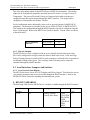
This is the only analog output on the MFT B-Series, HART flow transmitter. This analog
output can be configured to output the measured process Flow Rate , Average Velocity or
Temperature. The process Flow and Velocity are linearized and scaled according to a
configured range that can be entered through the HART interface. This output can be
configured to correspond to the Primary Variable.
Device malfunction can be indicated by down-scale or up-scale current (NAMUR NE 43
compliant). The direction is selectable by the user as LOW OUTPUT or HIGH OUTPUT.
This setting is not configurable through the HART interface but can be configured using the
meter’s local keypad. Refer to the MFTB User Guide for details. Current values are shown
in the table below.
Direction
Device malfunction
indication
Values (mA)
Down: less than
3.6
Up: greater than
21.0
4.2.2 Discrete Outputs
The MFT B-Series can be configured with up to two optically isolated solid state relays.
DO1 can be configured to energize when any alarm or fault event occurs. If the Air Purge
Sensor Cleaning System is installed, DO2 is used to energize a solenoid valve for periodic or
on-demand cleaning of the sensor. The Air Purge Sensor Cleaning can be setup and
controlled through the HART interface.
4.3 Local Interfaces, Jumpers And Switches
4.3.1 Local Controls And Displays
The MFT B-Series has a local 2x16 LCD display and 20-key keypad. This allows the user to
view/change parameters that are not accessible through the HART interface. Refer to the
MFTB User Guide for details regarding the onboard menu system.
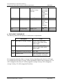
5. DEVICE VARIABLES
The following Table lists the MFTB Device Variables available through the HART interface.
Device Variable Name
Number
0, 246
PV
Revision A, Release Date: 6.30.2010
Description
Units
Primary Variable
(Usually Flow Rate)
SCFM,
SCFH, PPM,
PPH, SLPM,
SCMH,
KGM, KGH,
SFPM,
SMPS
HART Class
Code
72
Page 7 of 42
Kurz Instruments, Inc. Document 360209-AQ
Document Title: MFT B-Series HART Field Device Specification
HART FDS
1, 247
SV
Secondary Variable
(usually Average
Velocity)
2, 248
3, 249
TV
QV
Process Temperature
Totalized Flow Rate
244
245
Percent Range
Loop Current
Output % FS
Analog Out mA
SCFM,
SCFH, PPM,
PPH, SLPM,
SCMH,
KGM, KGH,
SFPM,
SMPS
degF, degC
Cubic Ft,
Pounds,
Liters, Cubic
Meter,
Kilograms,
Feet, Meter
None
mA
67
64
71
72
72
6. DYNAMIC VARIABLES
The following Table lists the Dynamic Variables that are implemented.
Description
Units
PV
Flow Rate or Average Velocity
SCFM, SCFH, PPM, PPH,
SLPM, SCMH, KGM, KGH,
SFPM, SMPS
SV
Flow Rate or Average Velocity
SCFM, SCFH, PPM, PPH,
SLPM, SCMH, KGM, KGH,
SFPM, SMPS
TV
Temperature of the process gas
degC, degF
QV
Totalized Flow
Cubic Ft, Pounds, Liters, Cubic
Meter, Kilograms, Feet, Meter
PV is mapped to either Flow Rate or Average Velocity depending on the selection of PV units.
SV is mapped to Flow Rate or Average Velocity depending on which value is mapped to PV (ie
if PV is mapped to Flow Rate, SV will be mapped to Average Velocity; if PV is mapped to
Average Velocity, SV will be mapped to Flow Rate).
Revision A, Release Date: 6.30.2010
Page 8 of 42
Kurz Instruments, Inc. Document 360209-AQ
Document Title: MFT B-Series HART Field Device Specification
HART FDS
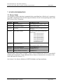
7. STATUS INFORMATION
7.1 Device Status
The Field Device Status byte that is contained in the second data byte of the device’s response to
any HART command provides the following bit definitions for the current operating status of the
MFT B-Series Flow Transmitter.
Bit Mask
Definition
Conditions to set bit
0x80 (bit 7)
Device Malfunction
Any FaultIndex bit except bits 7, 28-31
0x40 (bit 6)
Configuration Changed
Any parameter change
0x20 (bit 5)
Cold Start
Whenever a power cycle/reboot occurs on
the MFTB
0x10 (bit 4)
More Status Available
0x08 (bit 3)
Loop Current Fixed
Set when any bits in the following status
bytes are set:
Device Specific Status 0
Device Specific Status 1
Device Specific Status 2
Device Specific Status 3
Device Specific Status 4
Device Specific Status 5
Extended Device Status
Standardized Status 0
OperationStatus bit 1,
Device Specific Status 5, bits 0, 1, 2, 3, 4
0x04 (bit 2)
Loop Current Saturated
OperationStatus bit 3
0x02 (bit 1)
Non-Primary Variable Out of Limits
FaultIndex bits 0-16
0x01 (bit 0)
Primary Variable Out of Limits
FaultIndex bit 7
When the Bit #4 “More Status Available” or Bit #7 “Device Malfunction” bits are set, the HOST
should send Command 48 – Read Additional Device Status to determine the exact nature of the
status indication (See Section 7.3)
See Section 11 for bitwise definition of MFTB FaultIndex and OperationStatus.
Revision A, Release Date: 6.30.2010
Page 9 of 42
Kurz Instruments, Inc. Document 360209-AQ
Document Title: MFT B-Series HART Field Device Specification
HART FDS
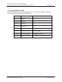
7.2 Extended Device Status
The Extended Device Status byte contained in byte 6 of command 48 Response Data Byte
contains the following bitwise status information:
Bit Mask
Definition
Conditions to set bit
0x80 (bit 7)
Undefined
NA
0x40 (bit 6)
Undefined
NA
0x20 (bit 5)
Undefined
NA
0x10 (bit 4)
Undefined
NA
0x08 (bit 3)
Undefined
NA
0x04 (bit 2)
Critical Power Failure
Not Used by MFTB
0x02 (bit 1)
Device Variable Alert
FaultIndex bits 7, 28-31
0x01 (bit 0)
Maintenance Required
Any FaultIndex bit excluding bits 7, 28-31
Revision A, Release Date: 6.30.2010
Page 10 of 42
Kurz Instruments, Inc. Document 360209-AQ
Document Title: MFT B-Series HART Field Device Specification
HART FDS
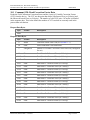
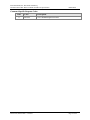
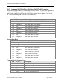
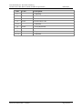
7.3 Additional Device Status (Command #48)
Command #48 returns 9 bytes of additional device status data for the field device. This
command should be sent whenever Bit #4 (More Status Available) or Bit #7 (Device
Malfunction) is set in the Device Status byte to determine the exact nature of the alert, warning,
alarm, or malfunction.
The following bitwise status indications are provided in the Additional Device Status response:
Byte
Byte 0
Device Specific Status 0
MFTB FaultIndex Byte 0
Byte 1
Device Specific Status 1
MFTB FaultIndex Byte 1
Byte 2
Device Specific Status 2
MFTB FaultIndex Byte 2
Byte 3
Device Specific Status 3
MFTB FaultIndex Byte 3
Bit
0
Meaning
RP resistance above high limit
1
RP resistance below low limit
2
RTC resistance above high limit
3
RTC resistance below low limit
4
Wire Resistance above high limit
5
Sensor RPS lead open circuit
6
High sensor or wire leakage
current. S-GND below 100K ohms
7
Flow rate above design limit
0-1
2
ADC failed to convert data
3
Sensor control stop responding
4
Sensor control crowbar engaged
5
Sensor type does not match config
6
Abnormal sensor node voltages
7
Unable to write new config file
0
1-7
Sensor type does not match board
Undefined
0-3
4
5
Undefined
HART Warning: Subsystem Fail
Sensor leak warning S-GND below
100K ohms
Power was applied (momentary)
Change made to configuration
(momentary)
Device in Diagnostic Mode
MFTB SensorTestFlag is set
Fixed current output
6
7
Byte 4
Device Specific Status 4
0
1
2
3
Revision A, Release Date: 6.30.2010
Undefined
Fault Event in MFTB – ie any bit
in FaultIndex is set except
POWER_ON and
CONFIG_CHANGE
Analog output is saturated
Page 11 of 42
Kurz Instruments, Inc. Document 360209-AQ
Document Title: MFT B-Series HART Field Device Specification
4
MFTB Alarm 1
5
MFTB Alarm 2
6-7
Byte 5
Device Specific Status 5
See Section 7.2
Byte 7
Device Operating Mode
Byte 8
Standardized Status 0
Undefined
0
Zero Drift Test in progress
1
Mid-span Drift Test in progress
2
Full-span Drift Test in progress
3
Drift Check Cycle All Tests
4
Purge Start Flag
5-7
Byte 6
Extended Device Status
Undefined
0
Maintenance Required
1
Device Variable Alert
2-7
NOT USED
by MFTB
NOT USED
by MFTB
HART FDS
Undefined
Undefined
Undefined
"Undefined" bits are always set to 0.
The bits in the FaultIndex are set or cleared by the self-test executed at power up, or following a
reset or self-test command. They are also set by any error/failure detected during continuous
self-testing while the flow meter is operational.
Revision A, Release Date: 6.30.2010
Page 12 of 42
Kurz Instruments, Inc. Document 360209-AQ
Document Title: MFT B-Series HART Field Device Specification
HART FDS
8. UNIVERSAL COMMANDS
All Universal Commands are implemented as specified in the HART Universal Command
Specification – HCF_SPEC-127, including Command 38 – Reset Configuration Changed Flag
and Command 48 – Read Additional Device Status.
Command #3 – Read Dynamic Variables and Loop Current, returns PV, SV, TV (Temperature),
QV (Totalized Flow) for a total of 24 bytes of response data.
Command #9 – Read Device Variables with Status; the following Device Variable Codes are
applicable – 00=PV, 01=SV, 02=TV, 03=QV.
9. COMMON-PRACTICE COMMANDS
9.1 Supported Commands
The following common-practice commands are implemented:
34
Write PV Damping Value
35
Write PV Range Values
36
Set PV Upper Range Value
37
Set PV Lower Range Value
40
Enter/Exit Fixed Current Mode
41
Perform Device Self-Test
42
Perform Master Reset
44
Write PV Units
45
Trim AO1 DAC Zero
46
Trim AO1 DAC Span
9.2 Burst Mode
This Field Device does not support Burst Mode.
9.3 Catch Device Variable
This Field Device does not support Catch Device Variable.
Revision A, Release Date: 6.30.2010
Page 13 of 42
Kurz Instruments, Inc. Document 360209-AQ
Document Title: MFT B-Series HART Field Device Specification
HART FDS
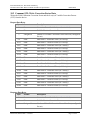
10. DEVICE-SPECIFIC COMMANDS
The following device-specific commands are implemented:
128
Read Correction Factor Data
129
Write Correction Factor Data
130
Read Current Correction Factor
131
Read Flow Area
132
Write Flow Area
133
Read Last Cal Date
137
Read Purge Parameters
138
Write Purge Parameters
139
Start Purge Cycle
140
Read Zero-Mid-Span Drift Check Parameters
141
Write Zero-Mid-Span Drift Check Parameters
142
Read Zero-Mid-Span Drift Check Results
143
Start Zero-Mid-Span Drift Check Test
144
Read Diagnostic Data
145
Reset Totalizer
146
Read Standard Conditions
147
Write Standard Conditions
Revision A, Release Date: 6.30.2010
Page 14 of 42
Kurz Instruments, Inc. Document 360209-AQ
Document Title: MFT B-Series HART Field Device Specification
HART FDS
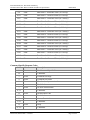
10.1 Command 128: Read Correction Factor Data
Reads the Field Calibration Correction Factor and the 8 set(s) of Variable Correction Factors
(VCF) from the device. The VCF are data pairs that define a Reference Flow (or Velocity) and
the Observed/Actual Flow (or Velocity). The number of valid VCF pairs - NCorrPts is included
in the response data. This value defines the number of VCF sets that are currently used in the
process data calculations.
Request Data Bytes
Byte
Format
Description
None
Response Data Bytes
Byte
Format
Description
0
Enum
Correction Factor Unit Code (see Section 11.1)
1-4
Float
Field Calibration Correction Factor
Unsigned-8
Number of Variable Correction Factor Data Sets (configured
for use)
6-9
Float
Data Point 1 - Reference Flow (or Velocity)
10-13
Float
Data Point 1 – Observed Flow (or Velocity)
14-17
Float
Data Point 2 – Reference Flow (or Velocity)
18-21
Float
Data Point 2 – Observed Flow (or Velocity)
22-25
Float
Data Point 3 – Reference Flow (or Velocity)
26-29
Float
Data Point 3 – Observed Flow (or Velocity)
30-33
Float
Data Point 4 – Reference Flow (or Velocity)
34-37
Float
Data Point 4 – Observed Flow (or Velocity)
38-41
Float
Data Point 5 – Reference Flow (or Velocity)
42-45
Float
Data Point 5 – Observed Flow (or Velocity)
46-49
Float
Data Point 6 – Reference Flow (or Velocity)
50-53
Float
Data Point 6 – Observed Flow (or Velocity)
54-57
Float
Data Point 7 – Reference Flow (or Velocity)
58-61
Float
Data Point 7 – Observed Flow (or Velocity)
62-65
Float
Data Point 8 – Reference Flow (or Velocity)
66-69
Float
Data Point 8 – Observed Flow (or Velocity)
5
Revision A, Release Date: 6.30.2010
Page 15 of 42
Kurz Instruments, Inc. Document 360209-AQ
Document Title: MFT B-Series HART Field Device Specification
HART FDS
Command-Specific Response Codes
Code
Class
Description
0
Success
Revision A, Release Date: 6.30.2010
No Command-Specific Errors
Page 16 of 42
Kurz Instruments, Inc. Document 360209-AQ
Document Title: MFT B-Series HART Field Device Specification
HART FDS
10.2 Command 129: Write Correction Factor Data
Writes the Field Calibration Correction Factor and the 8 set(s) of Variable Correction Factors
(VCF) from the device.
Request Data Bytes
Byte
Format
Description
0
Enum
Correction Factor Unit Code (see Section 11.1)
1-4
Float
Field Calibration Correction Factor
Unsigned-8
Number of Variable Correction Factor Data Sets (configured
for use)
6-9
Float
Data Point 1 - Reference Flow (or Velocity)
10-13
Float
Data Point 1 – Observed Flow (or Velocity)
14-17
Float
Data Point 2 – Reference Flow (or Velocity)
18-21
Float
Data Point 2 – Observed Flow (or Velocity)
22-25
Float
Data Point 3 – Reference Flow (or Velocity)
26-29
Float
Data Point 3 – Observed Flow (or Velocity)
30-33
Float
Data Point 4 – Reference Flow (or Velocity)
34-37
Float
Data Point 4 – Observed Flow (or Velocity)
38-41
Float
Data Point 5 – Reference Flow (or Velocity)
42-45
Float
Data Point 5 – Observed Flow (or Velocity)
46-49
Float
Data Point 6 – Reference Flow (or Velocity)
50-53
Float
Data Point 6 – Observed Flow (or Velocity)
54-57
Float
Data Point 7 – Reference Flow (or Velocity)
58-61
Float
Data Point 7 – Observed Flow (or Velocity)
62-65
Float
Data Point 8 – Reference Flow (or Velocity)
66-69
Float
Data Point 8 – Observed Flow (or Velocity)
5
Response Data Bytes
Byte
Format
Description
0
Enum
Correction Factor Unit Code (see Section 11.1)
1-4
Float
Field Calibration Correction Factor
Unsigned-8
Number of Variable Correction Factor Data Sets (configured
for use)
5
Revision A, Release Date: 6.30.2010
Page 17 of 42
Kurz Instruments, Inc. Document 360209-AQ
Document Title: MFT B-Series HART Field Device Specification
6-9
Float
Data Point 1 - Reference Flow (or Velocity)
10-13
Float
Data Point 1 – Observed Flow (or Velocity)
14-17
Float
Data Point 2 – Reference Flow (or Velocity)
18-21
Float
Data Point 2 – Observed Flow (or Velocity)
22-25
Float
Data Point 3 – Reference Flow (or Velocity)
26-29
Float
Data Point 3 – Observed Flow (or Velocity)
30-33
Float
Data Point 4 – Reference Flow (or Velocity)
34-37
Float
Data Point 4 – Observed Flow (or Velocity)
38-41
Float
Data Point 5 – Reference Flow (or Velocity)
42-45
Float
Data Point 5 – Observed Flow (or Velocity)
46-49
Float
Data Point 6 – Reference Flow (or Velocity)
50-53
Float
Data Point 6 – Observed Flow (or Velocity)
54-57
Float
Data Point 7 – Reference Flow (or Velocity)
58-61
Float
Data Point 7 – Observed Flow (or Velocity)
62-65
Float
Data Point 8 – Reference Flow (or Velocity)
66-69
Float
Data Point 8 – Observed Flow (or Velocity)
HART FDS
Command-Specific Response Codes
Code
Class
Description
0
Success
1-2
No Command-Specific Errors
Undefined
3
Error
Parameter too large
4
Error
Parameter too small
5
Error
Too few data bytes received
6
7
Undefined
Error
8-11
12
Undefined
Error
13-15
16
Invalid Units Code
Undefined
Error
17-31
32
In Write Protect Mode
Access Restricted
Undefined
Error
33-127
Revision A, Release Date: 6.30.2010
Busy
Undefined
Page 18 of 42
Kurz Instruments, Inc. Document 360209-AQ
Document Title: MFT B-Series HART Field Device Specification
HART FDS
10.3 Command 130: Read Current Correction Factor
Reads the Total Correction Factor from the device.
Request Data Bytes
Byte
Format
Description
None
Response Data Bytes
Byte
Format
0-3
Float
Description
Total Correction Factor
Command-Specific Response Codes
Code
Class
Description
0
Success
Revision A, Release Date: 6.30.2010
No Command-Specific Errors
Page 19 of 42
Kurz Instruments, Inc. Document 360209-AQ
Document Title: MFT B-Series HART Field Device Specification
HART FDS
10.4 Command 131: Read Flow Area
Read the Flow Area from the device.
Request Data Bytes
Byte
Format
Description
None
Response Data Bytes
Byte
Format
Description
0-3
Float
Flow Area
4
Enum
Flow Area Unit Code
Command-Specific Response Codes
Code
Class
Description
0
Success
Revision A, Release Date: 6.30.2010
No Command-Specific Errors
Page 20 of 42
Kurz Instruments, Inc. Document 360209-AQ
Document Title: MFT B-Series HART Field Device Specification
HART FDS
10.5 Command 132: Write Flow Area
Writes the Flow Area to the device.
Request Data Bytes
Byte
Format
0-3
Float
Response Data Bytes
Byte
Format
0-3
Float
Description
Flow Area
Description
Flow Area
Command-Specific Response Codes
Code
Class
Description
0
Success
1-2
No Command-Specific Errors
Undefined
3
Error
Parameter too large
4
Error
Parameter too small
5
Error
Too few data bytes received
6
7
Undefined
Error
8-11
12
Undefined
Error
13-15
16
Invalid Units Code
Undefined
Error
17-31
32
In Write Protect Mode
Access Restricted
Undefined
Error
33-127
Revision A, Release Date: 6.30.2010
Busy
Undefined
Page 21 of 42
Kurz Instruments, Inc. Document 360209-AQ
Document Title: MFT B-Series HART Field Device Specification
HART FDS
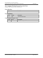
10.6 Command 133: Read Last Cal Date
Reads the Last Calibration Date from the device. The device returns the Last Calibration Date as
a date string in the form MM-DD-YYYY.
Request Data Bytes
Byte
Format
Description
None
Response Data Bytes
Byte
Format
0-17
Latin-1
Description
Last Calibration Date
Command-Specific Response Codes
Code
Class
Description
0
Success
Revision A, Release Date: 6.30.2010
No Command-Specific Errors
Page 22 of 42
Kurz Instruments, Inc. Document 360209-AQ
Document Title: MFT B-Series HART Field Device Specification
HART FDS
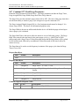
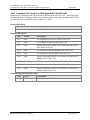
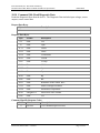
10.7 Command 137: Read Purge Parameters
Reads the Purge Parameters from the device. The Purge parameters include the Purge Timer,
Purge Assigned DO, Purge Width, Purge Hold Time, Purge Interval.
The Purge Timer sets the automatic purge feature ON or OFF. The state of the purge timer does
not affect the ability to initiate a purge cycle using device specific command #139.
The Purge Assigned Digital Output (DO) is a fixed assignment and cannot be changed. It is
always setup as DO2. The data is for informational purposes only.
The Purge Width is the time in milliseconds that the device will hold the purge solenoid open
when a purge cycle is initiated.
The Purge Hold Time is the time to allow the sensor to recover following a purge. The Purge
Hold Time entered is the total time for the entire purge cycle (e.g., a Hold Time of 2000
milliseconds with a Purge Time of 500 milliseconds means that the Purge Relay will be pulsed
for 500 milliseconds, followed by an additional 1500 milliseconds of idle time to allow for
sensor recovery).
The Purge Interval is used to set the frequency in minutes of the purge cycle when the Purge
Timer is set to ON.
Request Data Bytes
Byte
Format
Description
None
Response Data Bytes
Byte
Format
Description
0
Unsigned-8
Purge Timer – 0 = OFF, 1 = ON
1
Unsigned-8
Assigned Digital Output for the Air Purge Sensor Cleaning
System
2-3
Unsigned-16
Purge Width
4-5
Unsigned-16
Purge Hold Time
6-7
Unsigned-32
Purge Interval
Command-Specific Response Codes
Code
Class
Description
0
Success
Revision A, Release Date: 6.30.2010
No Command-Specific Errors
Page 23 of 42
Kurz Instruments, Inc. Document 360209-AQ
Document Title: MFT B-Series HART Field Device Specification
HART FDS
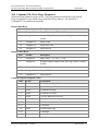
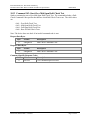
10.8 Command 138: Write Purge Parameters
Writes the Purge Parameters to the device. The Purge parameters include the Purge Switch,
Purge Assigned DO, Purge Width, Purge Hold Time, Purge Interval. See Section 10.7 –
Command 137 for parameter descriptions.
Request Data Bytes
Byte
Format
Description
0
Unsigned-8
Purge Timer – 0 = OFF, 1 = ON
1
Unsigned-8
Assigned Digital Output for the Air Purge Sensor Cleaning
System
2-3
Unsigned-16
Purge Width
4-5
Unsigned-16
Purge Hold Time
6-9
Unsigned-32
Purge Interval
Response Data Bytes
Byte
Format
Description
0
Unsigned-8
Purge Timer – 0 = OFF, 1 = ON
1
Unsigned-8
Assigned Digital Output for the Air Purge Sensor Cleaning
System
2-3
Unsigned-16
Purge Width
4-5
Unsigned-16
Purge Hold Time
6-9
Unsigned-32
Purge Interval
Command-Specific Response Codes
Code
Class
Description
0
Success
1-2
No Command-Specific Errors
Undefined
3
Error
Parameter too large
4
Error
Parameter too small
5
Error
Too few data bytes received
6
7
Undefined
Error
8-11
12
Undefined
Error
13-15
16
In Write Protect Mode
Invalid Units Code
Undefined
Error
Revision A, Release Date: 6.30.2010
Access Restricted
Page 24 of 42
Kurz Instruments, Inc. Document 360209-AQ
Document Title: MFT B-Series HART Field Device Specification
Code
Class
17-31
32
HART FDS
Description
Undefined
Error
33-127
Revision A, Release Date: 6.30.2010
Busy
Undefined
Page 25 of 42
Kurz Instruments, Inc. Document 360209-AQ
Document Title: MFT B-Series HART Field Device Specification
HART FDS
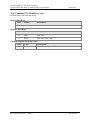
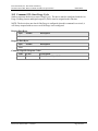
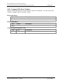
10.9 Command 139: Start Purge Cycle
Sends a request to the device to start a Purge Cycle. The device must be configured with the Air
Purge Cleaning System and digital output #2 (DO2) must be assigned to this function.
NOTE: The device does not check if the Purge is configured when this command is received; it
will always respond with success even if the Purge is not configured.
Request Data Bytes
Byte
Format
Description
None
Response Data Bytes
Byte
Format
Description
None
Command-Specific Response Codes
Code
Class
Description
0
Success
Revision A, Release Date: 6.30.2010
No Command-Specific Errors
Page 26 of 42
Kurz Instruments, Inc. Document 360209-AQ
Document Title: MFT B-Series HART Field Device Specification
HART FDS
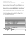
10.10 Command 140: Read Zero-Mid-Span Drift Check Parameters
Reads the Zero-Mid-Span Drift Check parameters from the device. The Drift Check parameters
include the ON/OFF status of the Auto Drift Check, the Time Interval of the Auto Drift Check,
and for each of the Drift Check Tests the % of FS drive voltage and test duration.
The Auto Drift Check Timer configures the internal timer in the device to initiate the Drift Check
Tests at a specified interval when it is set to ON. The Drift Check Timer has no effect on
triggering the Drift Check Tests using device specific command #143 (ie the user can initiate a
Drift Check Test using command #143 if the Drift Check Timer is OFF).
The Drift Check Time Interval defines the periodic interval, in hours that the Drift Check Tests
will be initiated by the internal timer.
The % of FS drive voltage and test duration defines the amplitude of the output signal and
duration that the output signal is applied for each Drift Check Test. The amplitude is given as a
% of full scale of the independent voltage source which is 3.3V. For example, if 10.0% is
entered for the % of FS for the Zero Drift Check Test, then 0.33V (10% of 3.3V) will be applied
to the 4-20mA output for the Drift Check at Zero.
Request Data Bytes
Byte
Format
Description
None
Response Data Bytes
Byte
Format
Description
0
Unsigned-8
Auto Drift Check ON/OFF – 0=OFF, 1=ON
1-2
Unsigned-16
Auto Drift Check Time Interval
3-6
Float
Zero Drift Check % Full Scale
7-8
Unsigned-16
Zero Drift Check Duration
9-12
Float
Mid Drift Check % Full Scale
13-14
Unsigned-16
Mid Drift Check Duration
15-18
Float
Span Drift Check Full Scale
19-20
Unsigned-16
Span Drift Check Duration
Command-Specific Response Codes
Code
Class
Description
0
Success
Revision A, Release Date: 6.30.2010
No Command-Specific Errors
Page 27 of 42
Kurz Instruments, Inc. Document 360209-AQ
Document Title: MFT B-Series HART Field Device Specification
HART FDS
10.11 Command 141: Write Zero-Mid-Span Drift Check Parameters
Writes the Zero-Mid-Span Drift Check parameters from the device. The Drift Check parameters
include the ON/OFF status of the Auto Drift Check, the Time Interval of the Auto Drift Check,
and for each of the Drift Check Tests the % of FS drive voltage and test duration. See Section
10.10 for detailed description of the Drift Check Parameters.
Request Data Bytes
Byte
Format
Description
0
Unsigned-8
Auto Drift Check ON/OFF – 0=OFF, 1=ON
1-2
Unsigned-16
Auto Drift Check Time Interval
3-6
Float
Zero Drift Check % Full Scale
7-8
Unsigned-16
Zero Drift Check Duration
9-12
Float
Mid Drift Check % Full Scale
13-14
Unsigned-16
Mid Drift Check Duration
15-18
Float
Span Drift Check Full Scale
19-20
Unsigned-16
Span Drift Check Duration
Response Data Bytes
Byte
Format
Description
0
Unsigned-8
Auto Drift Check ON/OFF – 0=OFF, 1=ON
1-2
Unsigned-16
Auto Drift Check Time Interval
3-6
Float
Zero Drift Check % Full Scale
7-8
Unsigned-16
Zero Drift Check Duration
9-12
Float
Mid Drift Check % Full Scale
13-14
Unsigned-16
Mid Drift Check Duration
15-18
Float
Span Drift Check Full Scale
19-20
Unsigned-16
Span Drift Check Duration
Command-Specific Response Codes
Code
Class
Description
0
Success
1-2
No Command-Specific Errors
Undefined
3
Error
Parameter too large
4
Error
Parameter too small
5
Error
Too few data bytes received
Revision A, Release Date: 6.30.2010
Page 28 of 42
Kurz Instruments, Inc. Document 360209-AQ
Document Title: MFT B-Series HART Field Device Specification
Code
Class
6
7
Error
Error
Invalid Units Code
Undefined
Error
17-31
32
In Write Protect Mode
Undefined
13-15
16
Description
Undefined
8-11
12
HART FDS
Access Restricted
Undefined
Error
33-127
Revision A, Release Date: 6.30.2010
Busy
Undefined
Page 29 of 42
Kurz Instruments, Inc. Document 360209-AQ
Document Title: MFT B-Series HART Field Device Specification
HART FDS
10.12 Command 142: Read Zero-Mid-Span Drift Check Results
Reads the Zero-Mid-Span Drift Check results of the last Drift Check Test run. The Drift Check
Results include the VCal Input and the corresponding output of the ADC during the Drift Check
Test as well as the % Difference between these two values.
Request Data Bytes
Byte
Format
Description
None
Response Data Bytes
Byte
Format
Description
0-3
Float
VCal Input used for the Zero Drift Check Test
4-7
Float
VCal Output for the Zero Drift Check Test
8-11
Float
Percent Difference between VCal In and VCal Out for the
Zero Drift Check Test
12-15
Float
VCal Input used for the MidSpan Drift Check Test
16-19
Float
VCal Output for the MidSpan Drift Check Test
20-23
Float
Percent Difference between VCal In and VCal Out for the
MidSpan Drift Check Test
24-27
Float
VCal Input used for the FullSpan Drift Check Test
28-31
Float
VCal Output for the FullSpan Drift Check Test
32-35
Float
Percent Difference between VCal In and VCal Out for the
FullSpan Drift Check Test
Command-Specific Response Codes
Code
Class
Description
0
Success
Revision A, Release Date: 6.30.2010
No Command-Specific Errors
Page 30 of 42
Kurz Instruments, Inc. Document 360209-AQ
Document Title: MFT B-Series HART Field Device Specification
HART FDS
10.13 Command 143: Start Zero-Mid-Span Drift Check Test
Sends a command to start a Zero-Mid-Span Drift Check Test. The command includes a Drift
Check Command Code specifier that defines which Drift Check Test to run. The valid values
are:
0x01 – Zero Drift Check Test
0x02 – Mid-Span Drift Check Test
0x04 – Full-Span Drift Check Test
0x08 – Run All Drift Check Tests
Note: The device does not check if an invalid command code is sent
Request Data Bytes
Byte
Format
0
Unsigned-8
Response Data Bytes
Byte
Format
0
Unsigned-8
Description
Drift Check Command Code
Description
Drift Check Command Code
Command-Specific Response Codes
Code
Class
Description
0
Success
Revision A, Release Date: 6.30.2010
No Command-Specific Errors
Page 31 of 42
Kurz Instruments, Inc. Document 360209-AQ
Document Title: MFT B-Series HART Field Device Specification
HART FDS
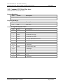
10.14 Command 144: Read Diagnostic Data
Reads the Diagnostic Data from the device. The Diagnostic Data includes input voltages, sensor
outputs, sensor control data.
Request Data Bytes
Byte
Format
Description
None
Response Data Bytes
Byte
Format
Description
0-3
Float
VPs
4-7
Float
VIph
8-11
Float
VRtch
12-15
Float
VRtcl
16-19
Float
VLeakSense
20-23
Float
VExtIn
24-27
Float
VTemp
28-31
Float
VCal
32-35
Float
Irp
36-39
Float
Prp
40-43
Float
Rp
44-47
Float
Rtc
48-51
Float
Resistance of the Sensor Wire
52-55
Float
Sensor Leakage Resistance
56-59
Float
Electronics Temperature
60-63
Unsigned-32
Device Run Time counter
64-67
Float
VLl
Command-Specific Response Codes
Code
Class
Description
0
Success
Revision A, Release Date: 6.30.2010
No Command-Specific Errors
Page 32 of 42
Kurz Instruments, Inc. Document 360209-AQ
Document Title: MFT B-Series HART Field Device Specification
HART FDS
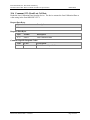
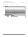
10.15 Command 145: Reset Totalizer
Sends a command to the device to reset the Flow Totalizer Accumulator. The value of the Flow
Totalizer is mapped to the QV dynamic variable.
Request Data Bytes
Byte
Format
Description
None
Response Data Bytes
Byte
Format
Description
None
Command-Specific Response Codes
Code
Class
Description
0
Success
Revision A, Release Date: 6.30.2010
No Command-Specific Errors
Page 33 of 42
Kurz Instruments, Inc. Document 360209-AQ
Document Title: MFT B-Series HART Field Device Specification
HART FDS
10.16 Command 146: Read Standard Conditions
Reads the Standard Temperature and Pressure parameters from the device.
Request Data Bytes
Byte
Format
Description
None
Response Data Bytes
Byte
Format
Description
0
Enum
Standard Temperature Unit Code
1
Enum
Standard Pressure Unit Code
2-5
Float
Standard Temperature Value
6-9
Float
Standard Pressure Value
Command-Specific Response Codes
Code
Class
Description
0
Success
Revision A, Release Date: 6.30.2010
No Command-Specific Errors
Page 34 of 42
Kurz Instruments, Inc. Document 360209-AQ
Document Title: MFT B-Series HART Field Device Specification
HART FDS
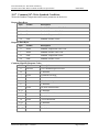
10.17 Command 147: Write Standard Conditions
Writes the Standard Temperature and Pressure parameters to the device.
Request Data Bytes
Byte
Format
Description
0
Enum
Standard Temperature Unit Code
1
Enum
Standard Pressure Unit Code
2-5
Float
Standard Temperature Value
6-9
Float
Standard Pressure Value
Response Data Bytes
Byte
Format
Description
0
Enum
Standard Temperature Unit Code
1
Enum
Standard Pressure Unit Code
2-5
Float
Standard Temperature Value
6-9
Float
Standard Pressure Value
Command-Specific Response Codes
Code
Class
Description
0
Success
1-2
No Command-Specific Errors
Undefined
3
Error
Parameter too large
4
Error
Parameter too small
5
Error
Too few data bytes received
6
7
Undefined
Error
8-11
12
Undefined
Error
13-15
16
Invalid Units Code
Undefined
Error
17-31
32
In Write Protect Mode
Access Restricted
Undefined
Error
33-127
Revision A, Release Date: 6.30.2010
Busy
Undefined
Page 35 of 42
Kurz Instruments, Inc. Document 360209-AQ
Document Title: MFT B-Series HART Field Device Specification
HART FDS
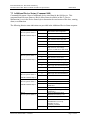
11. TABLES
11.1 MFTB FaultIndex bit definition
Bit
0
Definition
RP resistance above high limit
1
RP resistance below low limit
2
RTC resistance above high limit
3
RTC resistance below low limit
4
Wire Resistance above high limit
5
Sensor RPS lead open circuit
6
High sensor or wire leakage current. SGND below 100k ohms
7
Flow rate above design limit
8
Undefined
9
Undefined
10
ADC failed to convert data
11
Sensor control stop responding
12
Sensor control crowbar engaged
13
Sensor type does not match config
14
Abnormal sensor node voltages
15
Unable to write new config file
16
Sensor type does not match board
17-27
Undefined
28
HART Warning: Subsystem Fail
29
Sensor leak warning S-GND below 100k
ohms
30
Power was applied (momentary)
31
Change made to the configuration
(momentary)
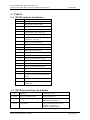
11.2 MFTB OperationStatus bit definition
Bit
Definition
Conditions to set bit
0 (0x01)
Device in diagnostic mode
SensorTestFlag is set
1 (0x02)
Device in current loop mode
HART.LoopCurrentMode & 0x80 ||
cHartCurrentControlFlag == 1
2 (0x04)
Device Fault
Any bit in FaultIndex is set except
POWER_ON (Bit#30) or
CONFIG_CHANGE (Bit #31)
Revision A, Release Date: 6.30.2010
Page 36 of 42
Kurz Instruments, Inc. Document 360209-AQ
Document Title: MFT B-Series HART Field Device Specification
3 (0x08)
4-20mA output is saturated
HART FDS
4-20mA signal is set to Low/High
saturation value
12. PERFORMANCE
12.1 Sampling Rates
See MFT B-Series Brochure for sampling rate specs.
12.2 Power-Up
On power up, the MFT B-Series goes through a self-test procedure (see section 12.4), which
takes approximately 2 seconds. Actual restart times can vary, the MFT B-Series Operation
Manual provides details on the parameters that can affect the flow meter device restart/power up
time. During this period, the device will not respond to HART commands, and the analog output
is set at the NE-43 alarm (< 3.6 mA or > 21.0 mA) . When the self-test is satisfactorily
completed, an additional delay of 20 seconds is required before a response to any HART
command is guaranteed.
12.3 Reset
Command 42 ("Device Reset") causes the device to reset its microprocessor. The resulting
restart is identical to the normal power up sequence. (See Section 12.2.)
Revision A, Release Date: 6.30.2010
Page 37 of 42
Kurz Instruments, Inc. Document 360209-AQ
Document Title: MFT B-Series HART Field Device Specification
HART FDS
12.4 Self-Test
The MFT B-Series does not support Command 41 – Self Test. The MFT B-Series performs
periodic self tests as part of its normal operational task. Any errors or faults determined during
the periodic self tests are recorded in the Device Specific Status bytes provided in the response to
Command 48 (“Read Additional Device Status”). The self test procedure is also executed at
power up, following Command 42 (“Device Reset”). For more details about the Built-in
Diagnostic capabilities see the MFT B-Series User Manual.
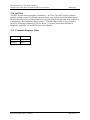
12.5 Command Response Times
Minimum
20ms
Typical
50ms
Maximum
100ms
Revision A, Release Date: 6.30.2010
Page 38 of 42
Kurz Instruments, Inc. Document 360209-AQ
Document Title: MFT B-Series HART Field Device Specification
HART FDS
12.6 Busy and Delayed-Response
Delayed-response is not used.
12.7 Long Messages
The largest data field used is in the response to Command 128 – Read Correction Factor Data
and Command 129 – Write Correction Factor Data. The number of bytes in the response data
field for these commands is 70 bytes.
12.8 Non-Volatile Memory
EEPROM is used to hold the device’s configuration parameters. New data is written to this
memory immediately on execution of a write command.
12.9 Modes
Fixed current mode is implemented, using Command 40. This mode is cleared by power loss or
reset.
12.10 Write Protection
The device does not have a write-protection function.
12.11 Damping
Damping is standard, affecting only the PV and the loop current signal.
Revision A, Release Date: 6.30.2010
Page 39 of 42
Kurz Instruments, Inc. Document 360209-AQ
Document Title: MFT B-Series HART Field Device Specification
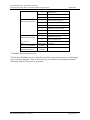
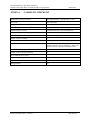
ANNEX A.
HART FDS
CAPABILITY CHECKLIST
Manufacturer, model and revision
Kurz Instruments Inc., MFT B-Series 2.0, rev. 1
Device type
Flow Transmitter
HART revision
7.0
Device Description available
Yes
Number and type of sensors
1 thermal anemometer, flow and temperature.
Number and type of actuators
none
Number and type of host side signals
1: 4 - 20mA analog
Number of Device Variables
6
Number of Dynamic Variables
6 – PV, SV, TV, QV, Percent Range, Loop Current
Mappable Dynamic Variables?
NO (The dynamic variables PV and SV are indirectly
mappable when PV units are changed; TV and QV are
fixed to represent temperature and totalized flow)
Number of common-practice commands
10
Number of device-specific commands
17
Bits of additional device status
Alternative operating modes
No
Burst mode
No
Write-protection
No
Revision A, Release Date: 6.30.2010
Page 40 of 42
Kurz Instruments, Inc. Document 360209-AQ
Document Title: MFT B-Series HART Field Device Specification
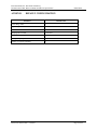
ANNEX B.
HART FDS
DEFAULT CONFIGURATION
Parameter
Default value
Lower Range Value
0
Upper Range Value
100000
PV Units
SCFM
Damping time constant
0.5 second
Fault-indication jumper
None
Write-protect jumper
None
Number of response preambles
5
Revision A, Release Date: 6.30.2010
Page 41 of 42
Kurz Instruments, Inc. Document 360209-AQ
Document Title: MFT B-Series HART Field Device Specification
ANNEX C.
A1.
HART FDS
REVISION HISTORY
Rev 1.0
Initial Release – June 28, 2010.
Revision A, Release Date: 6.30.2010
Page 42 of 42