1
www.ATMofAmerica.com
Toll Free:
Main Office:
24/7 Technical Support:
Fax:
(866) 5ATM-INC
(248) 932-5400
(866) 638-5918
(248) 932-5404
Triton RT2000
Manual
MODEL RT2000 SERIES USER MANUAL
DISCLAIMER
The manufacturer of the Automated Teller Machine (ATM) product(s) described
herein makes no representations or warranties, either expressed or implied, by or
with respect to anything in this manual, and shall not be liable for any implied
warranties of fitness for a particular purpose or for any indirect, special, or
consequential damages. Information in this document is subject to change without
notice and does not represent a commitment on the part of the manufacturer.
USE OF THIS PRODUCT IN A MANNER OTHER THAN THOSE
DESCRIBED IN THIS MANUAL MAY RESULT IN PERSONAL INJURY.
FCC COMPLIANCE (US units with modems)
Statement of Compliance: This equipment complies with Part 68 of the FCC rules.
Located in the control area of the ATM is the product label. This label lists the FCC
registration number and ringer equivalence number of the unit. If requested, this
information must be provided to the telephone company. USCO/FIC Codes: When
ordering service from the telephone company for the RT2000 ATM, the following
information should be supplied:
Universal Service Order Code (USOC): RJ-11C
The Facility Interface Code (FIC): 02LS2
Plug and Jack: The plug and jack used to connect this equipment to premise wiring
and telephone network must comply with the applicable FCC Part 68 rules and
requirements adopted by ACTA. A compliant telephone cord and modular plug is
provided with this product. The telephone cord is designed to be connected to a
compatible modular jack that is also compliant.
Ringer Equivalent Number (REN): The REN is used to determine the number of
the devices that may be connected to a telephone line. Excessive RENs on a
telephone line may result in the devices not ringing in response to an incoming call.
In most but not all areas, the sum of the RENs should not exceed five (5). To be
certain of the number devices that may be connected to a line, as determined by the
local RENs, contact the local telephone company.
Harm to the Network: If the RT2000 ATM causes harm to the telephone network, the
telephone company will notify the customer that a temporary discontinuation of
service may be required. If advanced notice is not possible, the telephone company
will notify the customer as soon as possible. You will be advised of your right to file
a complaint with the FCC if you believe it’s necessary.
ii
MODEL RT2000 SERIES USER MANUAL
Notification of Changes in Telephone Company Equipment: The telephone company
may make changes in its facilities, equipment, operations, or procedures that could
affect the operation of the equipment. If this happens, the telephone company will
provide advanced notice in order for you to make necessary modifications to maintain
uninterrupted service.
Repairs and Returns: If telecom compatibility trouble is experienced with the RT2000
ATM, please contact ATM Network at 1-800-929-0228.
If the equipment is causing harm to the network, the telephone company may request
that you disconnect the equipment until the problem is resolved. Repairs should be
made only by qualified factory representatives.
Party Lines: The RT2000 ATM must
not be used on party lines.
Alarm Equipment: The RT2000 ATM should have its own dedicated phone line. Do
not install the RT2000 on the same line as alarm equipment.
Electrical Safety Advisory: Telephone companies report that electrical surges,
typically lightening transients, are very destructive to customer equipment connected
to AC power sources. This has been identified as a major nationwide problem. A
commercially available, power surge suppressor, is recommended for use with the
RT2000 to minimize damage in the event of an electrical surge.
CANADIAN IC COMPLIANCE
NOTICE:
The Industry Canada label identifies certified equipment. This certification means
that the equipment meets telecommunications network protective, operational, and
safety requirements as prescribed in the appropriate terminal equipment technical
requirements document(s). The department does not guarantee the equipment will
operate to the user’s satisfaction.
iii
MODEL RT2000 SERIES USER MANUAL
Before installing this equipment, users should ensure that it is permissible to be
connected to the facilities of the local telecommunications company. The equipment must also be installed using an acceptable method of connection. The customer should be aware that compliance with the above conditions may not prevent
degradation of service in some situations.
Repairs to certified equipment should be coordinated by a representative designated by the supplier. Any repairs or alterations made by the user to this equipment
or equipment malfunctions may give the telecommunications company cause to
request the user to disconnect the equipment.
Users should ensure for their own protection that the electrical ground connections
of the power utility, telephone lines and internal metallic water pipe system, if present,
are connected together. This precaution may be particularly important in rural areas. Caution: Users should not attempt to make such connections themselves, but
should contact the appropriate electric inspection authority or electrician, as appropriate.
NOTICE:
The Ringer Equivalence Number (REN) assigned to each terminal device provides
an indication of the maximum number of terminals allowed to be connected to a
telephone interface. The termination on an interface may consist of any combination of devices subject only to the requirement that the sum of the Ringer Equivalence Numbers of all the devices does not exceed 5.
AVIS:
L’étiquette d’Industrie Canada identific le matériel homologué. Cette étiquette certifie
que le matériel est conforme aux normes de protection, d’exploitation et de sécurité
des réseaux de télécommunications, comme le prescrivent les documents concernant
les exigences techniques relatives au matériel terminal. Le Ministère n’assure toutefois
pas que le matériel fonctionnera à la satisfaction de l’utilisateur.
Avant d’installer ce matériel, l’utilisateur doit s’assurer qu’il est permis de le raccorder
aux installations de 1’entreprise locale de télécommunication. Le maté-riel doit
également être installé en suivant une méthode acceptée de raccordement. L’abonné
ne doit pas oublier qu’il est possible que la comformité aux conditions énoncées cidessus n’empêche pas la dégradation du service dans certaines situations.
iv
MODEL RT2000 SERIES USER MANUAL
Les réparations de matériel homologué doivent être coordonnées par un représentant
désigné par le fournisseur. L’entreprise de télécommunications peut demander à
I’utilisateur de débrancher un appareil à la suite de réparations ou de modifications
effectuées par l’utilisateur ou à cause de mauvais fonctionnement.
Pour sa propre protection, l’utilisateur doit s’assurer que tous les fils de mise à la
terre de la source d’énergie électrique, des lignes téléphoniques et des canalisations
d’eau métalliques, s’fl y en a, sont raccordés ensemble. Cette précaution est
particulièrement importante dans les régions rurales. Avertissement: L’utilisateur
ne doit pas tenter de faire ces raccordements lui-même; il doit avoir recours à an
service d’inspection des installations électriques, ou à un électricien, selon le cas.
AVIS:
L’indice d’équivalence de la sonnerie (IES) assigné à chaque dispositif terminal
indique le nombre maximal de terminaux qui peuvent étre raccordés à une interface. La terminaison d’une interface téléphonique peut consister en une combinaison
de quelques dispositifs, à la seule condition que la somme d’indices d’équivalence
de la sonnerie de tous les dispositifs n’exède pas 5.
UNITED KINGDOM
This equipment has been approved in accordance with Council Decision 98/482/
EC for pan-European single terminal connection to the Public Switched Telephone
Network (PSTN). However, due to differences between the individual PSTNs provided in the different countries, the approval does not, of itself, give unconditional
assurance of successful operation on every PSTN network termination point. In the
event of problems, contact your equipment supplier in the first instance. This unit
uses only Dual-Tone Multi-Frequency (DTMF) address signaling.
EMISSIONS (EMI)
US REQUIREMENTS
This device complies with Part 15 of the FCC rules. Operation is subject to the
following two (2) conditions:
1) This device may not cause harmful interference.
2) This device must accept any interference received, including interference that
may cause undesired operation.
v
MODEL RT2000 SERIES USER MANUAL
Note:
This equipment has been tested and found to comply with the limits for a Class A
digital device pursuant to Part 15 of FCC rules. These limits are designed to provide
reasonable protection against harmful interference when the equipment is operated
in a commercial environment. This equipment generates, uses, and can radiate radio
frequency energy and, if not installed and used in accordance with the instruction
manual, may cause harmful interference to radio communications. Operation of this
equipment in a residential area is likely to cause harmful interference in which case
the user will be required to correct the interference at his own expense. Changes or
modifications to this unit not expressly approved by the party responsible for
compliance could void the user’s authority to operate the equipment.
CANADIAN REQUIREMENTS
This digital apparatus does not exceed the Class A limits for radio noise emissions
from digital apparatus set in the Radio Interference Regulations of the Canadian
Department of Communications. This Class A digital apparatus complies with
Canadian ICES-003.
Le present appareil numerique n’emet pas de bruits radioelectriques depassant les
limites applicables aux appareils numeriques de la Class A prescrites dans le Reglement
sur le brouillage radioelectrique edicte par le ministere des Communications du
Canada. Cet appareil numerique de la classe A est conforme a la norme NMB-003
Canada.
UK REQUIREMENTS
Warning:
This is a Class A product. In a domestic environment, this product may cause radio
interference in which case the user may be required to take adequate measures.
vi
MODEL RT2000 SERIES USER MANUAL
Contents
SECTION 1 - INTRODUCTION ........................................................ 1
WHAT’S IN THIS MANUAL ................................................................................ 2
RT2000 MODELS ............................................................................................. 2
CLASS OF SERVICE (BUSINESS HOURS) ............................................................... 2
COMPUTER SYSTEM .......................................................................................... 2
FEATURE HIGHLIGHTS ....................................................................................... 3
STANDARD FEATURES ...................................................................................... 4
ACCESS AND TRANSACTION SECURITY ........................................................ 4
MULTIMEDIA INTERFACE (AUDIO/VIDEO) .................................................... 5
STORAGE OF FILES .................................................................................... 5
VOICE-ENABLED TRANSACTIONS ................................................................ 5
REMOTE MONITORING AND MANAGEMENT ................................................. 6
COMMUNICATIONS ..................................................................................... 6
CLOSE MANAGEMENT ............................................................................... 8
MESSAGES ............................................................................................... 8
TRANSACTION AND ACCOUNT TYPE CONFIGURATION ................................... 8
ELECTRONIC JOURNAL ............................................................................... 8
MULTI-LANGUAGE SUPPORT ...................................................................... 9
PRIZE COUPONS ........................................................................................ 9
RT2000 FEATURES AND SPECIFICATIONS ............................................................ 10
SECTION 2 - BASIC OPERATION ................................................... 13
INTRODUCTION ................................................................................................. 14
CONTROL PANEL LAYOUT ................................................................................. 14
KEYPAD OPERATION ........................................................................................ 15
ON-SCREEN KEYPAD OPERATION ...................................................................... 16
SCREEN FUNCTION KEYS .................................................................................. 16
MENU-BASED OPERATION ................................................................................ 17
ACCESSING MANAGEMENT FUNCTIONS .............................................................. 18
CUSTOMER TRANSACTIONS ................................................................................ 19
VOICE-ENABLED TRANSACTIONS ....................................................................... 20
SECTION 3 - INITIAL SETUP .......................................................... 21
PARAMETER CATEGORIES .................................................................................. 22
PARAMETER IMPORTANCE LEVELS ...................................................................... 23
SETUP PARAMETERS ......................................................................................... 24
SECTION 4 - CURRENCY HANDLING ............................................. 31
INTRODUCTION ................................................................................................. 32
DISPENSING MECHANISMS ................................................................................ 32
xv
MODEL RT2000 SERIES USER MANUAL
Contents
NOTE CONDITION ............................................................................................. 32
PREPARING NOTES ........................................................................................... 33
TDM-SERIES DISPENSERS ............................................................................... 34
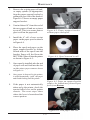
REMOVING THE CURRENCY CASSETTE(S) ............................................................ 34
LOADING THE CURRENCY CASSETTE(S) ............................................................... 34
REMOVING THE REJECT CASSETTE ...................................................................... 37
VERIFY OPERATION OF ALL DISPENSERS (TEST DISPENSE) ................................... 38
SECTION 5 - MANAGEMENT FUNCTIONS ....................................... 39
INTRODUCTION ................................................................................................. 40
ACCESSING THE MANAGEMENT FUNCTIONS MENU ............................................. 40
FUNCTION AVAILABILITY .................................................................................. 41
MANAGEMENT REPORTS ................................................................................... 42
CLOSE FUNCTIONS .......................................................................................... 44
INTRODUCTION ................................................................................................. 44
TERMINAL CLOSE FUNCTIONS ........................................................................... 46
SCHEDULE CLOSE ..................................................................................... 47
SEND TERMINAL TOTALS ........................................................................... 48
TRIAL CLOSE ........................................................................................... 49
DAY CLOSE .............................................................................................. 50
TRIAL CASSETTE CLOSE ............................................................................ 51
CASSETTE CLOSE FUNCTIONS ............................................................................ 52
SELECT CASSETTE(S) ................................................................................. 53
REPLENISH CASSETTE(S) ............................................................................ 54
SELECT CASSETTE(S) IN SERVICE ................................................................ 55
CASSETTE QUANTITY ................................................................................. 56
TRIAL CASSETTE CLOSE REPORT ................................................................ 57
DIAGNOSTICS ................................................................................................. 58
INTRODUCTION ................................................................................................. 58
DIAGNOSTICS MENU ........................................................................................ 59
TERMINAL STATUS FUNCTIONS ........................................................................... 60
CURRENT TERMINAL ERROR / TERMINAL ERROR HISTORY ............................ 61
RESET TERMINAL ERROR ........................................................................... 62
CONFIGURATION SUMMARY ........................................................................ 63
TRANSACTION TOTALS ...................................................................................... 64
SYSTEM DIAGNOSTICS ....................................................................................... 65
DISPENSER DIAGNOSTICS .................................................................................. 66
DISPENSER STATUS (MANAGEMENT REPORT) ............................................... 67
PURGE / TEST DISPENSE ............................................................................ 68
FORCE UNLOCK CASSETTE ......................................................................... 69
DISPENSER TOTALS / RESET DISPENSER ...................................................... 70
xvi
MODEL RT2000 SERIES USER MANUAL
Contents
CASSETTE PARAMETERS .................................................................................... 71
RELEARN BILL THICKNESS ........................................................................ 72
ALL CASSETTES LOCKED ........................................................................... 73
ACTIVE CASSETTE ..................................................................................... 74
CASSETTE IN SERVICE ................................................................................ 75
MULTIPLE AMOUNT ................................................................................. 76
DOCUMENT TYPE ..................................................................................... 77
NON-CASH / SECONDARY ITEM DESCRIPTION .............................................. 78
CARD READER DIAGNOSTICS ............................................................................. 79
CARD READER STATUS / TOTALS ................................................................ 80
SCAN CARD ............................................................................................. 81
PRINTER DIAGNOSTICS ...................................................................................... 82
DEVICE STATUS / RESET/TEST PRINTER ........................................................ 83
CONFIGURE PRINTER ................................................................................. 84
MODEM / ETHERNET DIAGNOSTICS .................................................................... 85
DEVICE STATUS ......................................................................................... 85
TEST (MODEM) / MODEM TOTALS ............................................................. 86
KEYPAD DIAGNOSTICS ...................................................................................... 87
DEVICE STATUS / TEST KEYPAD .................................................................. 87
ELECTRONIC JOURNAL .................................................................................... 88
INTRODUCTION ................................................................................................. 88
ELECTRONIC JOURNAL FUNCTIONS ..................................................................... 89
DISPLAY UNAUDITED RECORDS .................................................................. 90
DISPLAY LAST X ....................................................................................... 91
DISPLAY SELECTED RECORDS .................................................................... 92
CLEAR JOURNAL ....................................................................................... 93
ARCHIVE/DELETE JOURNAL / VIEW JOURNAL ARCHIVE ................................ 94
COUPONS / MESSAGES ..................................................................................... 95
INTRODUCTION ................................................................................................. 95
COUPON FUNCTIONS ........................................................................................ 97
COUPON TYPES ........................................................................................ 98
PROMPT / MINIMUM LEVEL ........................................................................ 99
MAXIMUM LEVEL / RANDOM ..................................................................... 100
MESSAGE / PRINT .................................................................................... 101
TERMINAL MESSAGES ...................................................................................... 102
WELCOME / STORE MESSAGE .................................................................... 103
MARKETING / EXIT MESSAGE .................................................................... 104
TERMINAL OWNER / SURCHARGE OWNER MESSAGE .................................... 105
NEWS TICKER MESSAGE ........................................................................... 106
DATE ANDTIME FUNCTION ................................................................................ 107
SET DATE / SET TIME/VOLUME .................................................................. 108/109
xvii
MODEL RT2000 SERIES USER MANUAL
Contents
SECTION 6 - MAINTENANCE ....................................................... 111
INTRODUCTION ................................................................................................. 111
REPLENISHING THE RECEIPT PAPER ................................................................... 111
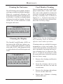
CLEANING THE ENCLOSURE .............................................................................. 115
CLEANING THE DISPLAY ................................................................................... 115
CARD READER CLEANING ................................................................................. 115
CARD READER PROBLEMS ................................................................................. 116
COMMUNICATION PROBLEMS ............................................................................. 116
SECTION 7 - ERROR RECOVERY ................................................ 117
INTRODUCTION ................................................................................................. 117
STATUS CONDITIONS ......................................................................................... 117
CLEARING TERMINAL STATUS ............................................................................ 119
ERROR RECOVERY PROCEDURES ........................................................................ 120
CLEAR STATUS USING MANAGEMENT FUNCTIONS ............................................... 121
RESTART USING MANAGEMENT FUNCTIONS ........................................................ 122
SHUTDOWN (REMOVE POWER) USING MANAGEMENT FUNCTIONS ........................ 123
SHUTDOWN/APPLY POWER USING POWER SUPPLY ON/OFF SWITCH .................. 124
STATUS (ERROR) CODES .................................... .........................................125 THRU 133
APPENDIX A - MECHANICAL / ELECTRONIC LOCKS .................... A-1
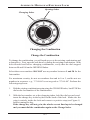
INTRODUCTION ................................................................................................. A-2
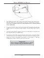
OPERATING THE MECHANICAL LOCK ................................................................. A-2
CHANGE THE COMBINATION .............................................................................. A-3
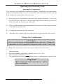
OPERATING THE ELECTRONIC LOCK .................................................................... A-4
CHANGE THE COMBINATION .............................................................................. A-4
LOCKOUT FEATURE .......................................................................................... A-5
BAD BATTERY/BATTERY REPLACEMENT ............................................................. A-5
APPENDIX B - OPERATOR SERVICE PANEL .................................. B-1
OPERATOR SERVICE PANEL FUNCTIONS .............................................................. B-2
MAIN MENU ................................................................................................... B-3
TERMINAL CLOSE FUNCTIONS ................................................................... B-4
DIAGNOSTICS ............................................................................................ B-4
ELECTRONIC JOURNAL ............................................................................... B-5
RESET TERMINAL ERROR ........................................................................... B-5
SHUT DOWN THE TERMINAL ...................................................................... B-5
RESTART THE TERMINAL ............................................................................ B-6
CONTRAST ADJUST ........................................................................................... B-6
xviii
MODEL RT2000 SERIES USER MANUAL
Contents
APPENDIX C - ADS GRAPHICS (COLOR DISPLAYS) .................... C-1
ADS GRAPHICS ................................................................................................ C-2
ADD NEW ................................................................................................ C-3
DELETE ................................................................................................... C-6
EDIT ........................................................................................................ C-7
MOVE UP ................................................................................................ C-9
MOVE DOWN ........................................................................................... C-10
COUPONS ........................................................................................................ C-11
GRAPHIC EXAMPLES ......................................................................................... C-13
UPDATING TERMINAL SOFTWARE ....................................................................... C-15
xix
SECTION 1
INTRODUCTION
1
MODEL RT2000 SERIES USER MANUAL
What’s in This Manual
This manual describes the operating features of the RT2000 ATM family. The setup and
operating procedures described are generally applicable to any RT2000 ATM. If your ATM
does not have the ability to perform some of the features described in this manual, it is
because your processor does not support the feature or the dispenser was purchased without that particular option.
RT2000 Models
The RT2000 family consists of a number of ATM models. The primary difference between
the various models is in the type of dispensing mechanism installed. The RT2000 family
includes a single cassette dispensing mechanism ( TDM-100 or TDM-150) or dual-cassette
mechanism (TDM-200 or TDM-250). Each series uses a dispensing mechanism that is
unique to that model.
Class of Service (Business Hours -vs-Level 1 Safe)
The basic RT2000 is UL certified for Business Hours Service and Level 1. Business Hours
means that the currency should be removed from the dispenser and stored in a safe location
when the business is closed to the public. Level 1 safe provides additional security and
the abilty to store currency during non-business hours. The basic-model ATM is a
rear-access machine, allowing access to the dispensing mechanism and currency cassette(s)
from the rear (vault door) of the unit.
Computer System
The RT2000 uses Windows® Intel X Scale™ PC platform, a robust technological design
that provides increased stability and improved speed while maintaining reliability and low
cost of ownership. The operating system supports Windows file formats for adding custom
logos and advertisements. In addition, it features Triton’s completely custom designed
motherboard.
2
INTRODUCTION
Feature Highlights
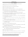
Important features of the RT2000 family are highlighted in the following list:
Highly reliable, state-of-the-art PC platform design.
Supports single and multi-cassette dispensing mechanisms.
Easy to install and configure by software.
Supports Dial-up, TCP/IP, VSAT, Radio Pad, or wireless communications.
Optional Operator Service Panel (OSP) allows access to Management functions for
security and ease of cassette loading and diagnostics.
Supports remote setup, configuration, and monitoring via Triton Connect™.
Satisfies Americans with Disabilities Act (ADA) specifications for height, access, and
the visually impaired via spoken word interface.
Choice of either a 5.7" monochrome (standard) or 6.5" VGA color (optional)Liquid
Crystal Display (LCD) screen.
Thermal printer with presenter prints 80 mm receipts, coupons, and management
reports.
Dip-style card reader supports magnetic stripe cards. Optional EMV “smart” card
reader or motorized card reader also available.
Encrypting PIN Pad (EPP) to comply with all international encryption standards,
Triple DES compliant.
Dispenses U.S. and international currency types.
Audio output provides user-action feedback as well as headphone accessible audible
prompting for sight-impaired users.
Management Functions provide indepth control of ATM operations.
16-key alphanumeric function keypad provides intuative menu selection and data
entry. External keyboard supported for maintenance purposes.
Integrated, lighted advertising panels.
Cabinets available in UL 291 Business Hours Service or UL 291 Level 1 Safe models.
High capacity electronic journal stores transactions for later printout and analysis.
Camera bracket mounting provisions with dedicated camera aperture.
3
MODEL RT2000 SERIES USER MANUAL
Model RT2000
Standard Features
Standard features of the RT2000 ATM are summarized in the following paragraphs.
Access and Transaction Security
Password-Controlled Access.
Access to the ATM’s Management Functions is protected by a password-based access
scheme. The ATM provides a “Master” password level of access and a flexible system of
“User-level” passwords. The master password provides full access to the ATM’s Management Functions, while User-level passwords provide access to a subset of those functions,
as determined by the holder of the master password.
Transaction Encryption.
The ATM protects all transaction and message traffic to and from the unit using strong
encryption techniques.
MAC Data Encryption Support
The ATM implements support for the Message Authentication Code (MAC) data encryption protocol. This capability is typically referred to as “MACing”. MACing is a protocol
supported by some processors and provides another level of encryption protection for
message traffic to and from the ATM.
4
INTRODUCTION
Encrypting PIN Pad (EPP) Entry Device Support
Secure EPP entry device is an encryption system that offers additional protection for the
customer PIN during entry at the ATM keypad. Complies with all international encryption
standards and is Triple DES compliant.
Multimedia Interface (Audio/Video)
Note
The 5.7” display (monochrome) doesn’t support graphics (welcome, banner, logo,
receipts, etc.). The 6.5” display (color) supports all Ad graphics except banners.
The ATM’s LCD screen can display text and graphical content in a wide range of colors
providing an interesting and dynamic experience to the customer. In addition, graphics can be
printed on receipts.
Text Effects
Various special effects such as blinking or fading can be applied to text messages that appear
on the LCD screen.
Ad Screens
An ad screen is a promotional or advertising graphic that is displayed on the LCD screen.
They can be displayed while the terminal is idle and while the customer transaction is being
processed. Ad screens can be loaded using a flash drive (USB) or downloaded via Triton
Connect.
Receipt Printer Graphics
Bit-mapped graphic images (BMP. only ) can be printed on the receipt. Like ad screen
graphics, receipt graphics can be loaded using a flash drive or downloaded via Triton Connect.
Audio Output
The integrated speakers enhance the media experience by offering audio output for the
visually impaired via spoken word interface.
Storage of Files
The ATM can store management reports, such as the results of close operations or diagnostic
tests. Graphics files are stored and retrieved from the internal hard disk. You may also save
reports to an external memory device.
Voice-Enabled Transactions
The ATM is able to provide voice feedback to sight-impaired users. By plugging a set of
headphones into the integrated headphone jack, users can receive spoken assistance as they
perform a transaction. See the section under Basic Operation for more information on this
feature.
5
MODEL RT2000 SERIES USER MANUAL
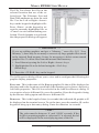
Remote Monitoring and Management
The RT2000 provides support for remote monitoring and management via the optional
Triton Connect software package.
Triton Connect is PC (Personal Computer) based software that enables you to perform
a wide range of monitoring and control functions from the convenience of a central
location. In many cases, the need to travel to the terminal location to perform configuration or data retrieval functions can be eliminated, along with the associated personnel
and travel costs.
Triton Connect can access your terminals via PSTN or wherever standard (voice-grade
analog) dial-up telephone service is available. For applications that require additional
flexibility, Triton Connect offers support for TCP/IP (Ethernet), VSAT (Very Small
Aperture Terminal), and other communication methods.
The Triton Connect host computer can monitor your ATM 24 hours a day, seven days
a week, and can receive an incoming call from the ATM if there is a system error or
service is required.
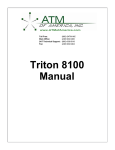
Triton terminals
Triton Connect PC
Triton Connect communicates with r emote terminals.
6
INTRODUCTION
Communications
The RT2000 ATM supports communication with the transaction processor using a variety
of communications technologies. These include Dial-Up, VSAT, RadioPad, DataPak, and
Client-Server(Ethernet).
Dial-Up
This method uses PSTN (the standard telephone system) for communications. Because
your PC is a digital device, while the PSTN is primarily an analog medium, an internal
modem is used to access the PSTN network in order to contact the processor and process
transactions.
VSAT (Very Small Aperture Terminal)
The VSAT connection type is used with ATMs that support satellite-based communications. VSAT supports a wide range of communication protocols.
RadioPad
This is a wireless communications method used primarily in countries where an infrastructure of wired telephone service is not used or is unavailable, and functions as the equivalent
of a dial-up telephone system.
DATAPAK
The DATAPAK protocol enables the ATM to interface with designated DATAPAK intermediaries (in the Canadian market region), who in turn provide connectivity to the appropriate transaction processor. DATAPAK connectivity is typically faster and more cost-effective than a direct dial-up connection between the ATM and the transaction processor.
NOTE: This feature is only available for use in the Canadian market.
TCP/IP (Ethernet)
This method is used in applications where a central Local Area Network, or LAN, is used to
connect multiple ATMs to a central server. Each ATM is treated as a client node on the
network, while the server provides the interface to a transaction processing system.
7
MODEL RT2000 SERIES USER MANUAL
Close Management
A suite of close functions are provided to facilitate daily balancing of the ATM’s internal
record of transaction activity with the processor’s transaction records.
Day Close
The Day Close is normally completed as the final step in the daily balancing process, and is
used to clear the totals and switch to the next business day. This function prints a report
summarizing all of the activity recorded by the ATM since the last Day Close was completed.
Cassette Close
The Cassette Close option is used to perform cassette-specific close operations. This function provides a summary of activity on a selected cassette since the last Cassette Close was
performed.
Messages
These are informational messages that give important information to the customer
before, during, and after a transaction. Messages can be locally customized to meet local
requirements. They include greeting and exit messages, terminal owner and surcharge
owner identification, marketing messages, and news tickers.
Transaction andAccount Type Configuration
This feature enables the terminal operator to select the types of transactions (transfers or
balance inquiries) or accounts (e.g. savings or credit card) that will be presented to the
customer. This feature does not affect the availability of checking account withdrawal transactions, which are always presented.
Electronic Journal
The ATM stores transaction records, status and other activity data in a journal record that is
maintained in the ATM’s processor module. The information in the electronic journal is
maintained in a safe and secure environment and can store up to 32, 768 records.
This information can be retrieved at a later date. When needed, just the information desired
can be recalled and a printout of those records can be made. Typically, the journal should be
printed out whenever a Day Close is completed, although this is not a requirement.
8
INTRODUCTION
Normally, journal data is printed by the unit’s receipt printer, but with the optional Triton
Connect software package the information can be sent to a remote PC for storage and
subsequent analysis.
Journal data can also be locally archived using the ATM’s internal memory. Even after old
journal records have been printed to the receipt printer, uploaded to Triton Connect, or
locally archived, they can still be read and printed again. Old records are retained in the
electronic journal until the maximum storage limit of the journal has been met at which time
the journal must be printed or cleared.
Multi-Language Support
The ATM has a screen language option. This option allows the terminal user to select a
preferred language (such as Spanish or French) to conduct a transaction.
Prize Coupons
The ATM may be configured to award “prize coupons” to customers on a random chance or
a withdrawal amount-determined basis. Coupons are always available in the form of printed
messages presented to the customer on a separate receipt.
There are two methods of awarding coupons: Random or Level.
Random
This method awards coupons randomly within a specified percentage range, such as 5% of
transactions.
Level
This approach awards a coupon to each customer that withdraws an amount equal to or
greater than a specific dollar value.
9
MODEL RT2000 SERIES USER MANUAL
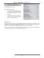
RT2000 Fe ature s and Spe cifications
Compute r Sys te m
Standard
Processor
200 MHz Intel XScale ®
Memory
(BIOS and Program)
32 Mbytes
64 Mbytes
Memory (RAM)
64 Mbytes
128 Mbytes
Serial Ports
5
USB 1.1
4 master
PCMCIA
2 - Type II
Audio
AC97 CODEC stereo output
Ethernet
10/100 Base- T
RJ- 45 connector
Operating System
Microsoft Windows ®
(CE.NET 4.1)
Motherboard
Designer/Manufacturer
Triton
(proprietary design)
Physical Design
Single board computer w/one
connector for ease of service
Electronic Journal
32,768 records
Language Support
3 - (English, Spanish,
Canadian French)
Dis play Sys te m
Standard
Optional
Liquid Crystal Display
5.7" mono (145 mm)
6.5" color (165 mm)
LCD Technology
Color Depth
Resolution
Power Comsumption
Active Matrix TFT
16 Gray
262, 144
320 x 240 (5.7'')
VGA 640 x 480
(6.5'')
10 Watts (Max)
380 cd/m2 (nits)
Brightness
Interface
Optional
Direct digital control
10
INTRODUCTION
RT2000 Fe ature s and Spe cifications
Printe r
Standard
Optional
Paper Size
80 mm
Print Resolution
8 dots / mm
Print Area
72 mm wide
Print Speed
75 mm / sec
Print Capability
Thermal text, bar codes
(Color display)
graphics (BMP. image)
Card Re ade r
Standard
Optional
Interface
RS- 232C
Track Configuration
Track 1 and 2
EMV Level 1 compliant
w/track 1,2,3 magstripe
Smart Card
Insertion Method
Dip
Motorized
D is pe ns e r
Standard
Optional
TDM- 100
550 used notes
TDM- 150
1300 used notes
TDM- 200
2 cassettes, 550 used
notes per cassette
2 cassettes, 1300 used
notes per cassette
TDM- 250
Acce s s to D is able d
Standard
Optional
Voice Guidance
Complete voice- guided lead through
using text- to- speech synthesis
Compliance with
ADA and Canadian
Guidelines
100% compliant for accessibility and reach
(when properly installed)
Encrypting PIN Pad
K ey Pad Style
Number of K eys
Standard
Polymer, individual keys
16 on Main pad
8 Function keys
11
Optional
Metal, individual keys
Same
MODEL RT2000 SERIES USER MANUAL
RT2000 Fe ature s and Spe cifications
M is ce llane ous
Documentation
Standard
Complete "Help" files for Management Functions
(built in)
C ap ab le o f d iagno stics and
day/cassette close functions
from rear of cabinet
Operator Service
Panel
Vandalism Resistant
Vault Design
Serviceability
Vault Lock
Optional
6 mm tempered glass screen over LCD
UL 291 Business Hour
UL 291 Level 1
Modular design
Mean time to repair <5 minutes
Mechanical (LaGard)
(combo)
Electronic (LaGard 33)
MAS Hamilton Cencon
Security
survelliance
Camera mounting bracket
(dedicated camera aperture)
Media lead through
Indicators
3 LED bars
(card reader, printer, dispenser)
Communications
Standard
Dial- Up
56k modem
TCP/IP
10/100 Base- T Ethernet
Optional
Satellite
VSAT
Wireless
Various
Signage and
Adve rtis ing
Standard
Surcharge Notification
Area, Recessed
102 mm x 102 mm
Optional
On- Screen
All graphics formats supported
(Color display)
Coupons, Dispensed
From dual- cassette units
Coupons, Printed
Random and level based
Graphic capable (color display)
12
SECTION 2
BASIC OPERATION
13
MODEL RT2000 USER MANUAL
Introduction
This chapter describes the basic operation of the terminal. The following topics are
covered:
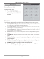
1. Control Panel Layout.Describes the layout of the terminal’s control panel.
2. Keypad Operation. Describes the use of the alphanumeric keypads.
3. Menu-Based Operation. This section gives a general overview of the terminal
display interface.
4. Accessing Management Functions. Describes the password entry procedure
that must be followed in order to access the Management Functions area.
5. Customer Transactions. Summarizes the actions involved in typical customer
transactions. In addition, the voice-enabled transactions feature is described.
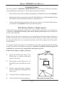
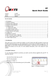
Control Panel Layout
The user interface of the terminal consists of the LCD display, receipt chute, card
reader, headphone jack (visually impaired), and 24 keys on three keypads. The
primary menu navigation keys are arranged in two four-key groups, one group on
either side of the LCD display. The main keypad consists of 10 alphanumeric keys,
two arrow keys, and four large control keys, all located in a 16-key group beneath the
LCD display.
The keypad has an integral raised Braille symbol to conform to the requirements of
the Americans with Disabilities Act. (See Figure 2-1)
Back Lit Sign
Control Panel
Light
Camera Aper ture
Menu Keys
Receipt Chute
LCD Screen
Card Reader
Main Keypad
Audio Jack
Bill Tray
Fig. 2-1. Control panel layout
14
BASIC OPERATION
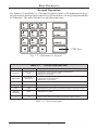
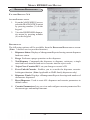
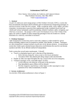
Keypad Operation
See Figure 2-2 and Table 2-1. The main keypad consists of 10 alphanumeric keys,
two arrow keys and four large control keys, all located in a 16-key group beneath the
LCD display. The table lists the keys and their functions.
1
QZ
ABC
2
3
4
5
6
GHI
JKL
7
8
PRS
TUV
ENTER
DEF
CLEAR
MNO
9
CANCEL
WXY
0
CTRL Key
Fig. 2-2. Alphanumeric keypad
TABLE 2-1 - RT2000 KEYBOARD MAP
K EY
KEYBOARD MAP
Left Arrow
Left Arrow or Up
Arrow
Right Arrow
Right Arrow or
Dow n Arrow
Enter
Enter
C an cel
E scap e
Clear
TAB
C T R L K ey
(Blank Key)
S p ace
0-9
0-9
ACTION
- Scroll Back in Current Field (for Combo and Edit Boxes).
- Change focus to the previous control.
- Moves up in a list control.
- Scroll Forw ard in Current Field (for Combo and Edit Boxes).
- Change focus to the next control.
- Moves dow n in a list control.
Selects ENTER on the Dialog or presses a selected button.
Selects CANCEL on the Dialog.
Move to Next Field on the Dialog. For multi-line text boxes, w ill insert a new line.
- Toggles a check box or radio button.
- Selects the focus button.
- Select the specified dialog box option.
- When inside an edit box, w ill display the specified numeric character.
Table 2-1. Keyboard map.
15
MODEL RT2000 USER MANUAL
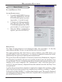
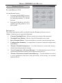
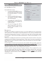
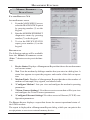
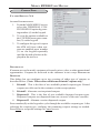
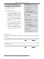
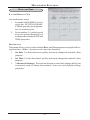
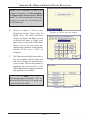
ON-SCREEN KEYPAD OPERATION
To enter text characters into the dialog boxes that are displayed by the Management Functions, press the F8 key to display the screen keyboard. Use the keys described below to
navigate and enter required data. (see Figure 2-3)
•
The arrow keys (left and right), the 8 key (Up), and the 0 key (Down) navigate the
keyboard.
•
•
•
•
•
•
Press the ENTER key to select the highlighted key entry.
Press the CTRL key to switch between upper and lower case characters.
Press the CANCEL key to Exit the keyboard.
Press the CLEAR key for the Backspace operation.
Press the 1 key to reposition the keyboard to another location on the display.
Press the 2 key to positon the cursor on a new line.
Figure 2-3. On-screen keyboard.
SCREEN FUNCTION KEYS
Refer to Figure 2-4. The eight keys, 4 on each side of the LCD, are called screen
function keys. They are used in the selection of screen options that can appear
along the right and left side of the display. These keys are designated F1 through F8.
A screen function key is only active when a corresponding function or menu option
is present next to that key.
Figure 2-4.
Screen function
keys.
F1
F2
F3
F4
F5
F6
F7
F8
16
BASIC OPERATION
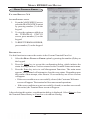
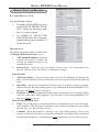
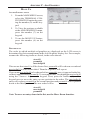
Menu-Based Operation
The terminal operates as a menu driven system. Messages and menu options presented on the LCD display screen guide the user’s actions. The desired menu option
is selected by pressing one of the screen keys located to the left and right of the
display. For the purpose of security, many screens timeout after a preset time interval, usually 30 seconds. The timeout length may vary depending on the function
being performed.
When a screen timeout occurs, a screen is presented which asks the user if more
time is needed. If the user chooses NO, the Customer Welcome screen will be
presented. If YES is chosen, the user is returned to the function that was active prior
to the timeout. If the user does not make a selection within an additional 30-second
countdown period the terminal will automatically go to the Customer Welcome
screen.
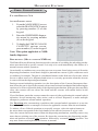
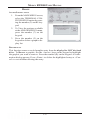
Shortly after the unit is turned on, the top menu will be displayed. An example top
menu is shown in Figure 2-5. From the top menu, you can either:
1.) Activate the terminal to perform customer transactions by pressing the key next
to Customer Transaction.
2.) Enter the terminal system management area by pressing the key next to
Management Functions.
If you do not select a menu choice within 30 seconds the terminal will automatically
default to the Customer Welcome screen (a benefit of this feature is that in the event
of a power interruption the terminal will automatically begin accepting customer
transactions shortly after power is restored).
Fig. 2-5. Top menu.
17
MODEL RT2000 USER MANUAL
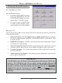
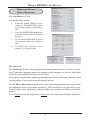
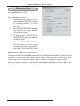
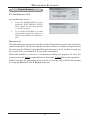
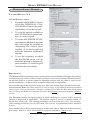
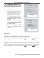
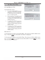
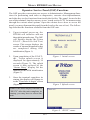
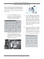
Accessing Management Functions
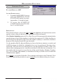
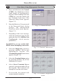
1.
At the Customer screen (Figure 2-6), press and hold down the <CTRL> key;
while holding down the <CTRL> key, press the <1> key. Release both keys. The
password entry prompt appears. (Figure 2-7)
2.
At the password entry screen, enter the Master or Users password.
Fig. 2-7. Password entry dialog.
Fig. 2-6. Customer screen.
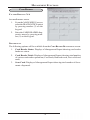
To access Management Functions, you must enter an appropriate password in the
dialog box that appears.
The password will consist of a 2-digit ID code and a password of 4-12 digits; for
example, 051234 could be a password entry consisting of an ID code of 05 and a
password of 1234. Press the Enter button to accept the password entry or Cancel to
exit.
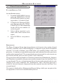
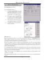
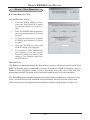
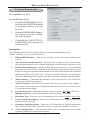
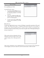
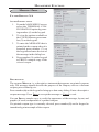
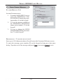
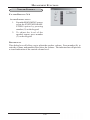
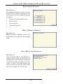
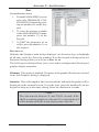
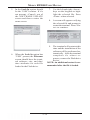
When a valid password is entered, the Management Functions main menu will be
displayed, as shown in Figure 2-8:
Fig. 2-8. Management Function main menu
18
BASIC OPERATION
DEFAULT MASTER PASSWORD
The default Master user ID is “00” and the password is “1234”. To enter Management Functions as the Master user, enter “001234” and press “Enter”.
Change the Master password immediately to prevent unauthorized access
to the ATM! See Configuration Manual forprocedures on changing the
Master password and other password Management procedures.
Once you have entered the Management Functions menu, you may perform any of the
functions allowed by the type of password used.
Introduction
This section sumarizes the actions involved in typical customer transactions. In
addition, the voice-enabled transactions feature is described.
Customer Transactions
A customer begins a transaction by selecting a service from the Customer screen
options (PaySpot™, CashWorks™, Western Union® or ATM- Get Cash Now).
They insert their ATM card into the card reader of the terminal. The card must be
inserted so that the magnetic stripe can be scanned by the card reader’s sensor. If
the customer inserts the card incorrectly, a warning message will be displayed,
accompanied by several beeps to get their attention.
If there is a problem reading a card, make sure the customer is inserting the card
correctly. Most problems are the result of inserting the card incorrectly.
Once the card has been read in successfully, a surcharge message, if applicable, may
be displayed (the surcharge message may be displayed at the end of the customer’s
transaction selection). The customer must then enter his secret Personal Identification Number, or PIN code. Once the PIN has been entered, the transaction type and
account are selected, and the desired amount of the transaction, if needed. The
transaction will be processed, typically in a matter of seconds.
If the transaction was processed successfully, the customer is prompted to retrieve
the requested cash (for withdrawal transactions) and/or the applicable transaction
receipt, as needed. If the transaction was declined, a short receipt indicating the
problem is printed.
19
MODEL RT2000 USER MANUAL
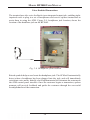
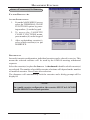
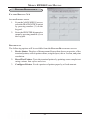
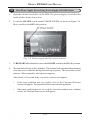
Voice-Enabled Transactions
The terminal provides voice feedback via an integrated output jack, enabling sightimpaired users to plug in a set of headphones and receive spoken instructions to
assist them in using the ATM. Figure 2-9, headphone jack location, shows the
location of the headhone jack on the RT2000.
Fig. 2-9. Headphone jack location.
Raised symbols helps a user locate the headphone jack. The ATM will automatically
detect when a headphone has been plugged into the jack, and will immediately
switch into voice mode. Initially, a brief spoken tutorial will orientate the customer to
the ATM control panel interface. Once the customer begins a transaction, spoken
prompts will provide feedback and guide the customer through the successful
accomplishment of the transaction.
20
SECTION 3
INITIAL SETUP
21
MODEL RT2000 USER MANUAL
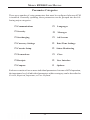
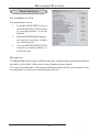
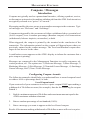
Parameter Categories
There are a number of setup parameters that must be configured when an ATM
is installed. Generally speaking, these parameters can be grouped into the following major categories.
Communications
Languages
Security
Messages
Surcharging
Ad Screens
Currency Settings
Date/Time Settings
Cassette Setup
Status Monitoring
Transactions
Close
Receipts
User Interface
Coupons
Options
Each area consists of one or more individual parameters. In terms of ATM operation,
the importance level of individual parameters within a category can be described as
Critical, Required, Important, or User-Defined.
22
INITIAL SETUP
Parameter Importance Levels
Critical
The parameters with this importance level are primarily those that represent the
minimum number of parameters that must be correctly configured in order to process
transactions. In addition, because of the importance of protecting access to the
ATM Management Functions, the access password parameters are also included in
this category. The primary parameters in this category include various communications and security (including access password) parameters.
Required
These parameters further satisfy your transaction processor’s setup or operational
requirements. Parameters in this area define the ability of your ATM to offer various
types of transactions, to correctly present those transactions to the customer and to
accurately record those transactions. Surcharging, Cassette Setup, and Account/
Transactions parameters fall into this category.
Important
These parameters are used to manage transaction activity record-keeping, enable remote monitoring of ATM operation, and to ensure receipts and other
records are accurately annotated with the correct date and time. Status Monitoring, Close, and Date/Time parameters are included in this category.
User-Defined
These parameters are configured at your discretion, and are used to customize
the appearance and functionality of the ATM to meet the unique language
needs of your intended customers, adjust user interface appearance, satisfy
advertising or promotional requirements, or meet other locale-specific requirements. The management of optional features is also included in this area. Languages, Receipts, Coupons, Messages, Ad /Graphics, and More Options parameters fall into this category.
NOTE: The importance-level of individual parameters as described in this manual is
provided as a general guide to assist you in understanding and prioritizing the setup
requirements of your ATM. If, after evaluating your unique requirements, you feel
that a parameter is more (or less) important to your particular needs, you are free to
treat that parameter accordingly.
23
MODEL RT2000 USER MANUAL
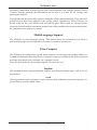
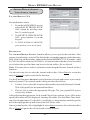
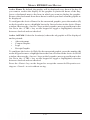
Setup Parameters
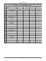
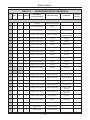
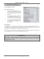
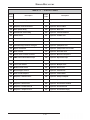
Table 3-1, Significance Levels, correlates each Management Functions area to the
significance levels of parameters in that area.
NOTE: The significance level of individual parameters as described in this manual is
provided as a general guide to assist you in understanding and prioritizing the setup
requirements of your ATM. If, after evaluating your unique requirements, you feel
that a parameter is more (or less) important to your particular needs, you are free to
treat that parameter accordingly.
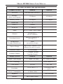
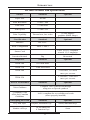
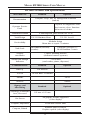
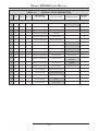
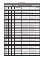
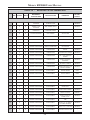
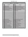
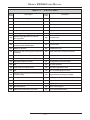
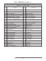
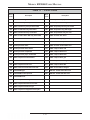
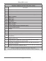
Tables 3-2 through 3-5 list Critical, Required, Important, and User Defined parameters, respectively. Each table lists the applicable Management Function area, Function option, Parameter name, and Factory default value for each parameter.
IN TABLE 3-2, CRITICALSETUPPARAMETERS, THE NAMES
OF THOSEPARAMETERS THATARETYPICALLY THEMINIMUM NUMBER REQUIRED IN ORDERTO PERFORM A
TRANSACTION HAVE BEEN HIGHLIGHTED.CHECK WITH
YOUR TRANSACTION PROCESSOR FOR YOUR SPECIFIC
REQUIREMENTS!
IMPORTANT: Although many of the ATM’s parameters have been set at the
factory, it is important to verify that the settings are appropriate for your needs.
Change the factory default values as necessary to reflect the actual settings you
require.
24
INITIAL SETUP
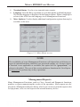
TABLE 3-1 MANAGEMENT FUNCTIONS AREA
1
LANGUAGE
2
SYSTEM PARAMETERS
3
COUPONS
4
MESSAGES
5
GENERAL PARAMETERS
6
ADS/GRAPHICS
7
OPTIONAL SCREENS
8
OPTIONAL SCREEN BUTTONS
9
COMMUNICATION
SIGNIFICANCE LEVELS
CRITICAL
REQUIRED
IMPORTANT
USER-DEFINED
X
X
X
X
X
X
X
X
X
X
X
X
X
X
X
10
DIAGNOSTICS
X
11
PASSWORD MAINTENANCE
X
12
KEY MANAGEMENT
X
13
CASSETTE PARAMETERS
X
X
X
X
14
CLOSE FUNCTIONS
X
15
WITHDRAWAL AMOUNTS
X
X
16
NOTE CONFIGURATION
X
17
SURCHARGE PROPERTIES
X
18
DATE/TIME
19
TRITON CONNECT
X
20
PRINTER
X
X
21
PREPAID PHONE
X
22
CHECK CASHING
X
23
MONEY TRANSFER
X
25
MODEL RT2000 USER MANUAL
TABLE 3-2 SD D
TDM-100
NMD-50
CRITICAL SETUP PARAMETERS
MANAGEMENT
FUNCTIONS AREA
FUNCTION OPTION
PARAMETER NAME
CONFIGURE MODEM
FACTORY
DEFAULT
1
X
X
X
DIAGNOSTICS
MODEM
2
X
X
X
PASSWORD MAINTENANCE
CHANGE USER PASWORD
3
X
X
X
PASSWORD MAINTENANCE
MODIFY USER ACCESS
*
4
X
X
X
PASSWORD MAINTENANCE
ADD USER
N/A
5
X
X
X
PASSWORD MAINTENANCE
REMOVE USER
N/A
6
X
X
X
SYSTEM PARAMETERS
SELECT SCREEN FILE
7
X
X
X
TERMINAL CONFIGURATION
GENERAL PARAMETERS
TERMINAL NUMBER
NONE
8
X
X
X
TERMINAL CONFIGURATION
CASSETTE SETUP
CASSETTE PARAMETERS
$0.00
*
001234
*
9
X
X
X
TERMINAL CONFIGURATION
COMMUNICATION
PRIMARY NUMBER
NONE
10
X
X
X
TERMINAL CONFIGURATION
COMMUNICATION
BACKUP NUMBER
NONE
11
X
X
X
TERMINAL CONFIGURATION
COMMUNICATION
ENABLE MAC-ING
*
*
12
X
X
X
TERMINAL CONFIGURATION
COMMUNICATION
COMMUNICATIONS
PROTOCOL
13
X
X
X
TERMINAL CONFIGURATION
COMMUNICATION
COMMUNICATIONS
MESSAGE
*
14
X
X
X
TERMINAL CONFIGURATION
COMMUNICATION
NUA NUMBER (DATAPAK)
*
15
X
X
X
KEY MANAGEMENT
ENTER MAC MASTER KEY
*
16
X
X
X
KEY MANAGEMENT
ENTER PIN MASTER KEY
*
17
X
X
X
KEY MANAGEMENT
INJECT MASTER KEYS
*
*
*
18
X
X
X
KEY MANAGEMENT
DOWNLOAD WORKING
KEYS
19
X
X
X
KEY MANAGEMENT
CHECK DIGITS
26
INITIAL SETUP
TABLE 3-3 -
REQUIRED SETUP PARAMETERS
SD D
TDM-100
NMD-50
MANAGEMENT
FUNCTIONS AREA
FUNCTION OPTION
PARAMETER NAME
FACTORY
DEFAULT
1
X
X
X
TERMINAL CLOSE
FUNCTIONS
CASSETTE CLOSE
CASSETTE QUANTITY
0
2
X
X
X
TERMINAL CONFIGURATION
GENERAL PARAMETERS
DEFAULT TRANSACTION
TYPE
*
3
X
X
X
TERMINAL CONFIGURATION
GENERAL PARAMETERS
DEFAULT ACCOUNT
TYPE
*
4
X
X
X
TERMINAL CONFIGURATION
TERMINAL MESSAGES
SURCHARGE OWNER
*
5
X
X
X
TERMINAL CONFIGURATION
CASSETTE SETUP
MAXIMUM CASH
$500.00
X
TERMINAL CONFIGURATION
CASSETTE SETUP
MAXIMUM NON-CASH
$0.00
6
7
X
X
X
TERMINAL CONFIGURATION
CASSETTE SETUP
EXTENDED AMOUNTS
DISABLED
8
X
X
X
TERMINAL CONFIGURATION
CASSETTE SETUP
FAST CASH
*
9
X
DIAGNOSTICS
DISPENSER
(CASSETTE PARAMETERS)
RELEARN BILL
THICKNESS
*
10
X
TERMINAL CONFIGURATION
CASSETTE SETUP
(CASSETTE PARAMETERS)
DOCUMENT TYPE
C ASH
NON-CASH ITEM
DESCRIPTION
NONE
11
X
TERMINAL CONFIGURATION
CASSETTE SETUP
(CASSETTE PARAMETERS)
12
X
TERMINAL CONFIGURATION
CASSETTE SETUP
(CASSETTE PARAMETERS)
SECONDARY ITEM
DESCRIPTION
NONE
13
X
TERMINAL CONFIGURATION
CASSETTE SETUP
(CASSETTE PARAMETERS)
NOTE CONFIGURATION
(BILL WIDTH)
*
14
X
TERMINAL CONFIGURATION
CASSETTE SETUP
(CASSETTE PARAMETERS)
NOTE CONFIGURATION
(BILL LENGTH)
*
15
X
TERMINAL CONFIGURATION
CASSETTE SETUP
(CASSETTE PARAMETERS)
NOTE CONFIGURATION
(VALUE)
*
NOTE CONFIGURATION
(VARIANT)
*
16
X
TERMINAL CONFIGURATION
CASSETTE SETUP
(CASSETTE PARAMETERS)
17
X
TERMINAL CONFIGURATION
CASSETTE SETUP
(CASSETTE PARAMETERS)
NOTE CONFIGURATION
(CODE)
*
X
TERMINAL CONFIGURATION
SURCHARGE PROPERTIES
ENABLE SURCHARGE
DISABLED
18
X
X
19
X
X
X
TERMINAL CONFIGURATION
SURCHARGE PROPERTIES
SURCHARGE AMOUNT
$0.00
20
X
X
X
TERMINAL CONFIGURATION
SURCHARGE PROPERTIES
SURCHARGE PERCENT
0%
LE S S E R
21
X
X
X
TERMINAL CONFIGURATION
SURCHARGE PROPERTIES
LESSER/GREATER
22
X
X
X
TERMINAL CONFIGURATION
SURCHARGE PROPERTIES
ALLOW ISO'S LISTED
*
23
X
X
X
TERMINAL CONFIGURATION
SURCHARGE PROPERTIES
ADD NEW ISO'S
NONE
24
X
X
X
TERMINAL CONFIGURATION
OPTIONAL SCREENS
SURCHARGE OPTION
BEGINNING
25
X
X
X
TERMINAL CONFIGURATION
OPTIONAL SCREENS
RECEIPT OPTION
*
*
26
X
X
X
TERMINAL CONFIGURATION
OPTIONAL SCREENS
ACCOUNT/TRANSACTION
SELECTION
27
X
X
X
TERMINAL CONFIGURATION
OPTIONAL SCREEN
BUTTONS
ACCOUNT SELECTION
*
TRANSACTION
SELECTION
*
FAST CASH SELECTION
*
28
X
X
X
TERMINAL CONFIGURATION
OPTIONAL SCREEN
BUTTONS
29
X
X
X
TERMINAL CONFIGURATION
OPTIONAL SCREEN
BUTTONS
27
MODEL RT2000 USER MANUAL
TABLE 3-4 - IMPORTANT SETUP PARAMETERS
SD D
TDM-100
NMD-50
MANAGEMENT
FUNCTIONS AREA
FUNCTION OPTION
1
X
X
X
TERMINAL CLOSE
FUNCTIONS
SCHEDULE CLOSE
DISABLED
2
X
X
X
TERMINAL CLOSE
FUNCTIONS
SEND TERMINAL TOTALS
DISABLED
3
X
X
X
DIAGNOSTICS
CONFIGURE PRINTER
*
4
X
X
X
SYSTEM PARAMETERS
DATE AND TIME
5
X
X
X
SYSTEM PARAMETERS
REGIONAL SETTINGS
6
X
X
X
TERMINAL CONFIGURATION
GENERAL PARAMETERS
STATUS MONITORING
DISABLED
7
X
X
X
TERMINAL CONFIGURATION
GENERAL PARAMETERS
HEARTBEAT MESSAGE
*
8
X
X
X
TERMINAL CONFIGURATION
GENERAL PARAMETERS
DELAY PERIOD
*
9
X
X
X
TERMINAL CONFIGURATION
COMMUNICATION
PREDIAL
DISABLED
10
X
X
X
TERMINAL CONFIGURATION
COMMUNICATION
COMMUNICATION HEADER
DISABLED
*
PARAMETER
SET DATE/TIME
FACTORY
DEFAULT
*
N/A
11
X
X
X
TERMINAL CONFIGURATION
COMMUNICATION
USE 12-BYTE SEQUENCE
NUMBER
12
X
X
X
TERMINAL CONFIGURATION
COMMUNICATION
ENABLE PERSISTENT
REVERSALS
DISABLED
13
X
X
X
TERMINAL CONFIGURATION
COMMUNICATION
REVERSAL ATTEMPTS
DISABLED
DISABLED
14
X
X
X
TERMINAL CONFIGURATION
COMMUNICATION
ENABLE REVERSALS FOR
PROTOCOL ERRORS
15
X
X
X
TERMINAL CONFIGURATION
TRITON CONNECT
PRIMARY NUMBER
NONE
16
X
X
X
TERMINAL CONFIGURATION
TRITON CONNECT
BACKUP NUMBER
NONE
17
X
X
X
TERMINAL CONFIGURATION
TRITON CONNECT
ALARM MONITOR PRIMARY
NONE
18
X
X
X
TERMINAL CONFIGURATION
TRITON CONNECT
ALARM MONITOR BACKUP
NONE
19
X
X
X
TERMINAL CONFIGURATION
TRITON CONNECT
MAX RETRIES
*
20
X
X
X
TERMINAL CONFIGURATION
TRITON CONNECT
REDIAL DELAY
*
21
X
X
X
TERMINAL CONFIGURATION
TRITON CONNECT
ENABLE TRITON CONNECT
DISABLED
22
X
X
X
TERMINAL CONFIGURATION
TRITON CONNECT
ENABLE CALLBACK
ENABLED
ENABLE SCHEDULED
JOURNAL CALLS
DISABLED
23
X
X
X
TERMINAL CONFIGURATION
TRITON CONNECT
24
X
X
X
TERMINAL CONFIGURATION
TRITON CONNECT
TIME
*
DISABLED
25
X
X
X
TERMINAL CONFIGURATION
TRITON CONNECT
ENABLE CALL AT NUMBER
OF JOURNAL RECORDS
26
X
X
X
TERMINAL CONFIGURATION
TRITON CONNECT
ENABLE CALL AT LOW CASH
DISABLED
27
X
X
X
TERMINAL CONFIGURATION
TRITON CONNECT
ENTER NEW ACCESS CODE
*
28
INITIAL SETUP
TABLE 3-5 - USER-DEFINED SETUP PARAMETERS
SD D
TDM-100
NMD-50
MANAGEMENT
FUNCTIONS AREAS
FUNCTION OPTION
1
X
X
X
LANGUAGE
ENGLISH/FRENCH/SPANISH
*
2
X
X
X
SYSTEM PARAMETERS
VOLUME
*
3
X
X
X
SYSTEM PARAMETERS
SCHEDULE REBOOT
ENABLE/DISABLE
TIME SET/DAY SELECT
*
4
X
X
X
TERMINAL CONFIGURATION
GENERAL PARAMETERS
DEFAULT LANGUAGE
(CUSTOMER SCREENS)
*
5
X
X
X
TERMINAL CONFIGURATION
COUPONS
COUPON
*
6
X
X
X
TERMINAL CONFIGURATION
COUPONS
PROMPT
*
7
X
X
X
TERMINAL CONFIGURATION
COUPONS
MINIMUM LEVEL
*
8
X
X
X
TERMINAL CONFIGURATION
COUPONS
MAXIMUM LEVEL
*
9
X
X
X
TERMINAL CONFIGURATION
COUPONS
RANDOM
*
10
X
X
X
TERMINAL CONFIGURATION
COUPONS
MESSAGE
*
11
X
X
X
TERMINAL CONFIGURATION
COUPONS
LAYOUT
*
12
X
X
X
TERMINAL CONFIGURATION
COUPONS
GRAPHIC
*
13
X
X
X
TERMINAL CONFIGURATION
COUPONS
PRINT
*
14
X
TERMINAL CONFIGURATION
COUPONS
CASSETTE
*
15
X
TERMINAL CONFIGURATION
COUPONS
COUNT
*
PARAMETER
FACTORY
DEFAULT
16
X
X
X
TERMINAL CONFIGURATION
TERMINAL MESSAGES
WELCOME MESSAGE
*
17
X
X
X
TERMINAL CONFIGURATION
TERMINAL MESSAGES
STORE MESSAGE
*
18
X
X
X
TERMINAL CONFIGURATION
TERMINAL MESSAGES
MARKETING MESSAGE
*
19
X
X
X
TERMINAL CONFIGURATION
TERMINAL MESSAGES
EXIT MESSAGE
*
20
X
X
X
TERMINAL CONFIGURATION
TERMINAL MESSAGES
TERMINAL OWNER
MESSAGE
*
21
X
X
X
TERMINAL CONFIGURATION
TERMINAL MESSAGES
NEWS TICKER
MESSAGE
*
22
X
X
X
TERMINAL CONFIGURATION
ADS / GRAPHICS
ADD NEW
*
PURCHASE
SELECTIONS
*
23
X
X
X
TERMINAL CONFIGURATION
OPTIONAL SCREEN
BUTTONS
24
X
X
X
MORE OPTIONS
PREPAID PHONE
*
25
X
X
X
MORE OPTIONS
CHECK CASHING
*
26
X
X
X
MORE OPTIONS
MONEY TRANSFER
*
29
SECTION 4
CURRENCY HANDLING
31
MODEL RT2000 USER MANUAL
Introduction
**CAUTION**
DO NOT RECYCLE REJECTED
NOTES INTO A CASSETTE!
Doing so could cause more rejects
and/or currency jams.
The purpose of this section of the manual is
to describe the procedures for: (1) removing
and replacing note cassettes, (2) loading cassettes, and (3) removing and replacing the
reject notes (as applicable). Information
conrcerning note handling and quality issues are explained where appropriate.
Note Condition
If possible, store currency at room temperature for at least eight hours before dispensing from the cassettes.
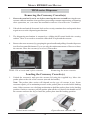
Dispensing Mechanisms
The RT2000 ATM use a variety of dispensing mechanisms. Depending upon
ATM model, the dispensing mechanism may
hold one or more note cassettes. The reject
collection method may use a reject compartment that is integrated into the note cassette, or a separate reject container. Currency capacity depends upon the dispenser
mechanism installed in the ATM, but is also
affected by note quality and thickness. Typical capacities are provided in the following
table:
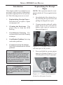
The number of rejects can be directly influenced by the technique used to load the cassettes and the quality of the currency. Notes
loaded into the cassettes must be in “fit”
condition if a high level of performance (low
reject and failure rate) is expected from the
unit. “Fit” notes do not possess any of the
defects listed here:
Used Note Defects
•
Adhesive or “sticky” substances on
the surface of the paper.
•
Tears extending more than 1/2” from
the edge of the currency.
•
Tears, holes, or missing sections in the
body of the currency.
•
Tape on the surface of the currency
used for repairing, patching or any other
purpose.
•
Staples, pins, or any other foreign body
attached to the notes.
•
Corner folds of a size greater than 1/2”
on either axis.
•
Two or more notes joined by any
means.
•
Excessively crumpled or crinkled.
RT2000 MODEL FAMILIES
DISPENSER
NUMBER OF CASSETTES
RECOMMENDED MAXIMUM
CAPACITY
TDM-100
Single
550 Notes (used)
TDM-150
Single
1300 Notes (used)
TDM-200
D u al
550 Notes (used)
per cassette
TDM-250
D u al
1300 Notes (used)
per cassette
Reject Cassette (All) - 100 used notes
The dispensing mechanism delivers the appropriate number of notes from the note
cassette(s) to fulfill the customer’s withdrawal request. The purpose of the reject
area or vault is to accept and hold notes that
have been transferred from the note
cassette(s) but not dispensed. Some situations that could cause the mechanism to reject notes are: (1) multiple notes stuck together and (2) note width too short or long.
Other conditions that could cause a reject
are described in the next section.
32
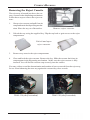
CURRENCYHANDLING
Preparing New or Uncirculated
Notes
New or Uncirculated Note Defects
•
All the conditions listed for used notes.
•
Excessive bowing due to conditions of
packing and storing.
•
New or uncirculated currency must be
“burst” and fully separated prior to
loading into cassettes.
•
Remove the band around each bundle
of notes. Separate the notes from each
other by:
•
Striking the bundle hard against the
edge of a table or similar object.
•
Flipping through each bundle of notes
in both directions at each end.
•
Using a note counter.
Preparing Notes
Use the following procedures to prepare
notes before inserting them into a note cassette.
Preparing Used Notes
•
Remove the band around each bundle
of notes.
•
Remove foreign objects (e.g. pins, paper clips, crumbs, etc.).
•
Remove torn or very worn notes.
•
Straighten any folded notes.
33
MODEL RT2000 USER MANUAL
TDM-series Dispenser
Removing the Currency Cassette(s)
1.
Ensure the terminal is not in use before removing the note cassette!
Removing the note
cassette while the machine is in operation (processing customer transactions, performing
close operations, etc.) can cause the terminal to enter an “Out of Service” condition!
2.
Unlock the mechanical/electronic lock on the security container door and open the door
to gain access to the dispensing mechanism.
3.
The dispensing mechanism is mounted to a sliding shelf located inside the security
cabinet. There is no need to extend the slide shelf to replenish the cassette.
4.
Remove the note cassette(s) by grasping the green handle and pulling from the dispenser
in a firm but controlled manor. Try to use only the minimum amount of force to release
the cassette. Place the cassette(s) on a level, flat surface.
Removing the note cassette.
TDM-150 w/ note and reject cassette.
Loading the Currency Cassette(s)
1.
Unlock the cassette(s) and open the cassette lid using the supplied key. Move the
pusher plate to the rear of the cassette (toward the handle).
Note: The pusher plate action will depend on the type of cassette in use. Some
cassettes require you to maintain pressure on the pusher plate as needed while loading
notes. Other cassettes use a locking mechanism to hold the packer plate in the loading
position. On these cassettes, pull the pusher-plate all the way back to the handle end of
the cassette and turn the key to latch the pusher plate into the loading position.
Open the note cassette lid.
Unlock note cassette.
34
CURRENCYHANDLING
Pull the packer back. Some cassettes
allow the pusher-plate to be latched
in position using the key-lock. (Insert)
2.
IMPORTANT: The shape of some notes may be affected by conditions of storage or
bundling, preventing them from forming neat even piles. If not corrected, such conditions
may cause notes to be rejected by the dispensing mechanism.
To compensate for the most common conditions of slanting or cupped note piles,
follow the directions given next.
Notes with no apparent shape problems are referred to as “common” notes.
•
Slanting Pile
To avoid dispensing problems caused by a
“slanting” pile, put the notes in neat bundles
of no more than ½ to ¾ inches in thickness
(100-200 notes). Turn every other bundle
around to minimize slanting of the pile
(bundle should have the same height on both
sides, if possible).
•
Alternate slanted bundles.
Dispense
opening.
Cupped bundle
To avoid dispensing problems caused by
cupped bundles, turn all the bundles with
the cupped side towards the dispense
opening of the note cassette (opposite
end from the handle).
Turn cupped sides towar d dispense
opening.
35
MODEL RT2000 USER MANUAL
•
Mixed (Slanting and Cupped)
bundles
Separate the mixed currency into neat
bundles of 100-200 notes of each type. Place
the cupped bundles nearest the dispense
opening of the cassette, with the cupped
side facing the opening. Turn every other
slanted bundle around to give the bundles
the same height on both sides and place after
the cupped bundles.
•
Old and New Notes
Always place the bundles containing old
notes into the cassette first (nearest the
handle) and bundles containing new notes
last (nearest the dispense opening).
•
Place old notes together .
Common notes
Simply place the prepared bundles in the
cassette.
3.
Make sure the note pile is as even as possible. If necessary, use your hands to smooth
and level the pile.
4.
On cassettes that do not use a pusher-plate locking mechanism, release the pusher plate
against the notes. If the cassette uses pusher-plate locking, turn the key to release the
catch, allowing the pusher plate to compress the notes.
5.
Close and lock the cassette. Remove
the key. Slide the cassette back into its
compartment in the dispensing
mechanism. Make sure the cassette is
fully inserted! You will feel the cassette
latch securely into the snap catches.
Load notes.
36
CURRENCYHANDLING
Removing the Reject Cassette
The reject tray is located just above the currency cassette in the dispensing mechanism.
Follow these steps to remove the reject cassette:
1.
2.
Grasp reject cassette and pull from its
compartment in the dispensing mechanism. Place the tray on a flat surface.
Remove reject cassette.
Unlock the tray using the supplied key. Flip the top back to gain access to the reject
compartment.
Unlock and open
reject cassette.
3.
Remove any notes in the reject compartment.
4.
Close and lock the reject cassette. Remove the key. Slide the cassette back into its
compartment in the dispensing mechanism. Make sure the reject cassette is fully
inserted! You will feel the cassette snap securely into the catches.
You may wish to record the denomination and number of notes removed from the reject tray,
for use when balancing the note tray against the cassette/day close records.
TDM-150 (shelf extended)
TDM-250 (shelf extended)
37
MODEL RT2000 USER MANUAL
Verify Operation ofAll Dispensers
1.
After completion of the “Cassette Close” procedures, close and lock the security
cabinet.
2.
In Management Functions Main Menu, select Diagnostics, then Dispenser.
3.
Select the Test Dispense option. Select either individual cassettes that are
installed [“A” ( single cassette dispenser) or “A” or “B” (dual-cassette
dispenser)) or “ALL CASSETTES ”. A prompt appears asking how many
notes to dispense (below). The test dispense operation will start.
4.
The Test Dispense command instructs the dispenser to dispense, minimum,
one note from each installed and operational cassette into the reject vault. This
test exercises the dispenser without sending notes to the exit.
5.
After completion of the Test Dispense, the following prompt is displayed below
- “Test Dispense Completed Successfully - Dispense Count , A: (# of notes), B:
#.
If you have the optional Operator Service Panel:
1.
After completion of the “Cassette Close” procedures, close and lock the security
cabinet.
2.
In the Main Menu screen, select Diagnostics, then Dispenser. Select the Test
Dispense option. Select either individual cassettes that are installed [“A” (
single cassette dispenser) or “A” or “B” (dual-cassette dispenser))or “ALL
CASSETTES ”. A prompt appears asking how many notes to dispense. The
test dispense operation will start.
3.
After completion of the Test Dispense, a prompt is displayed - “Test Dispense
Completed Successfully - Dispense Count , A: (# of notes), B: #.
38
SECTION 5
MANAGEMENT FUNCTIONS
39
MODEL RT2000 USER MANUAL
Introduction
This section describes the Management Functions available for controlling the
ATM. When the Customer Welcome screen is displayed, you can access the
Management Functions menu by following the procedure described next.
Accessing the Management Functions Menu
1.
Press and hold down the <CTRL> key; while holding down the <CTRL> key,
press the <1> key. Release both keys. After a moment the top menu will be
displayed.
2.
At the top menu (see Figure 5-1below), select MANAGEMENT FUNCTIONS
by pressing the F7 screen key (next to Management Function option).
F1
F2
F3
F4
F5
F6
F7
F8
Figure 5-1. Location of the F7 key (highlighted by the circle).
3.
Enter the Master or User password at the password entry display (see Figure 52 below).
Figure 5-2. Enter your
Master or User password at the Management
Functions screen.
40
MANAGEMENT FUNCTIONS
To access Management Functions, you must enter an appropriate password in the
dialog box that appears when the Management Functions option is selected. The
password will consist of a 2-digit ID codeand a password of 4-12 digits; for example,
051234 could be a password entry consisting of an ID code of 05 and a password of
1234. Press the Enter button to accept the entry or Cancel to exit. When a valid
password is entered, the Main Menu screen will be displayed. (Figure 5-3)
DEFAULT MASTER PASSWORD
The default Master user ID is “00” and the password is “1234”. To enter Management Functions as the Master user, enter “001234” and press ENTER.
CHANGE THE MASTER PASSWORD IMMEDIATELYTO PREVENT UNAUTHORIZED ACCESS TO THEATM!
Function Availability
Once you have entered the Main Menu, you may perform any of the functions
allowed by the type of password used (access level).
Each Main Menu option description will include the function name, instructions for
accessing the function, a description of the function, and any associated factory
default values.
The Main Menu screen allows the service provider/terminal operator to access the
following management functions:
1.
Close Functions. Used to perform Cassette Close, Day Close, Trial Close and
Schedule Close functions.
2.
Diagnostics. Used to perform terminal hardware testing, and to view test
results.
3.
Electronic Journal. Used to manage the ATM’s journal functions, such as
display/print and clearing actions.
4.
Password Maintenance. Used to add, modify, or delete terminal access
privileges.
5.
System Parameters. Used to shut down or restart the terminal, to configure
location-specific settings such as time and date, and to adjust the audio
volume.
6.
Terminal Configuration. Used to view/edit terminal operating parameters
such as surcharging, customer-screen language selection, communications,
status monitoring, ads/graphics and Triton Connect configuration.
7.
Key Management . Used to enter encryption keys, which protect
communcations between the ATM and the transaction processing service
provider.
41
MODEL RT2000 USER MANUAL
8.
Terminal Status. Used to view terminal status reports.
9.
Language. Press the 9 key repeatedly to cycle through the available languages.
The current language is displayed in the button caption. When a language is
selected, the ATM uses the language in all Management Functions.
0.
More Options. Used to display additional configuration options that may be
available to the user.
Figure 5-3. Main Menu screen.
NOTE
The availability of some Management Functions will depend on such factors as
types of optional hardware installed, user password options, etc. In cases where
a function is not applicable or available, the option will be “grayed out,” or
otherwise disabled. The rest of this section addresses functions the User/Operator may need to perform day-to-day operations.
Management Reports
Many Management Functions, such as Close, Journal and Diagnostic functions,
produce a report summarizing the results of the operation. Most reports are displayed in a Management Report dialog, which you can use to print the report to the
receipt printer, or to save the report to an external memory device.
42
MANAGEMENT FUNCTIONS
The buttons on the Management Report dialog let you perform the following actions:
(Figure 5-4)
1.
Page Up. Scrolls the report up a maximum of one full page.
2.
Home. Moves directly to the first page of the report.
3.
Print. Sends the report to the terminal receipt printer for hardcopy output.
4.
Page Down. Scrolls the report down a maximum of one full page.
5.
End. Moves directly to the last page of the report.
6.
Save To File. Saves the report as a text file to an external memory device.
Figure 5-4. Management Report menu.
43
MODEL RT2000 USER MANUAL
CLOSE FUNCTIONS
Introduction
Cassette and Day Close reports provide important information about the transactions being performed by your ATM. This information helps you manage the ATM
more effectively.
The ATM’s close functions are accessed through the Management Function’s
Terminal Close Functions menu.
Day Close
The Day Close report shows the cumulative value of all transactions (withdrawals,
transfers and balance inquiries) performed by the ATM since the previous Day
Close. The report also shows the corresponding host totals, allowing you to compare the ATM totals against the host processor records.
•
•
•
IMPORTANT
Perform a Day Close once each business day. Because the host processor also
performs a business-day close for the ATM, you should perform the Day Close
at the same time each day, at the time specified by your host processor. This will
help ensure the Day Close report reflects the host’s current business- day
totals for your ATM.
To help ensure Day Closes are performed at the same time each day you can use
the Schedule Close function, which automatically performs a Day Close each
day, at a time specified by the Change Schedule function.
The Day Close report shows totals accumulated by the host processor during
the business day, as stated earlier. In some cases, the host processor can make
use of the totals recorded by the ATM. In these cases, you can provide ATM
totals to the host processor during the Day Close, using the Send Terminal
Totals function.
44
MANAGEMENT FUNCTIONS
Cassette Close
The Cassette Close report shows current cassette activity, including total notes
dispensed and remaining and the total value of those notes, since the previous
Cassette Close was performed. This report can help you judge the volume of withdrawal activity and plan cassette replenishment activities accordingly.
•
IMPORTANT
Perform a Cassette Close before replenishing the currency in the cassette.
•
Performing a Cassette Close will reset the cassette activity totals to zero (0). The
Enter Cassette Quantity value is also reset to zero.
•
After performing a Cassette Close and replenishing the cash in the cassette,
enter the total number of bills loaded in the cassette, using the Enter Cassette
Quantity function.
It is very important that you always enter this value after performing a Cassette
Close! The ATM uses this starting number to calculate the quantity and
(monetary) amount of notes remaining in the cassette after each withdrawal.
Failure to enter the cassette quantity will result in negative-numbered totals
being listed in the Cassette Close report!
•
After you enter the cassette quantity, a Trial Cassette Close Report appears
which you can print or save to an external storage device. This is a record of the
beginning cassette balance. The cassette totals will not be cleared.
45
MODEL RT2000 USER MANUAL
TERMINAL CLOSE FUNCTIONS
FACTORY DEFAULT: N/A
ACCESS INSTRUCTIONS:
1.
From the MAIN MENU screen,
select the TERMINAL CLOSE
FUNCTIONS option by pressing number (1) on the keypad.
DESCRIPTION:
The TERMINAL CLOSE menu allows the terminal operator to perform the following
functions:
1.
Schedule Close. Used to enable/disable automatic Day Close.
2.
Send Terminal Totals (ON/OFF). Use to enable/disable automatic
transmission of terminal close totals to your transaction processing service
provider. Press this button to cycle the function between ON and OFF.
3.
Trial Close. Used to initiate a Trial Day Close.
4.
Day Close. Used to initiate a Day Close.
5.
Trial Cassette Close. Used to provide a receipt/record of the cassette(s)
balance.
6.
Cassette Close Functions . Used to access a menu of cassette close and
configuration functions.
46
MANAGEMENT FUNCTIONS
SCHEDULE CLOSE
FACTORY DEFAULT: OFF
ACCESS INSTRUCTIONS:
1.
From the MAIN MENU screen,
select the TERMINAL CLOSE
FUNCTIONS option by pressing number (1) on the keypad.
2.
To access the SCHEDULE
CLOSE function, press the number (1) on the keypad.
DESCRIPTION:
This function allows you to turn ON or OFF the SCHEDULE CLOSE function and to
specify a time of day at which a close operation will be performed.
If the Enable Schedule option is ON, a Day Close will be automatically initiated at the
specified time of day. If the checkbox is checked, the option is ON. If the checkbox is
not checked, the function is OFF. Press the number (1) key to switch the checkbox
between ON (checked) and OFF (not checked).
Use the number (2), (3), (4), and (5) keys to choose the hours, minutes, seconds, and
AM/PM settings at which the scheduled close is to be performed. Pressing a key
repeatedly will cause the associated field to cycle through the available values. The
current time setting appears in a small text window below the time set buttons. Use
the number (6) key to select a specific day of the week (Sunday, Monday, Tuesday,
etc.), or a a setting of EVERYDAY, to determine the day(s) of the week to which the
scheduled time applies.
Press Enter to accept the Schedule Close settings and return to the Terminal Close
Functions main dialog window or press Cancel to exit without making any changes.
47
MODEL RT2000 USER MANUAL
SEND TERMINAL TOTALS
FACTORY DEFAULT: OFF
ACCESS INSTRUCTIONS:
1.
From the MAIN MENU screen,
select the TERMINAL CLOSE
FUNCTIONS option by pressing number (1) on the keypad.
2.
To change the condition of the
SEND TERMINAL TOTALS
function to ON, press number (2)
on the keypad.
DESCRIPTION:
This function allows you to turn ON or OFF the SEND TERMINAL TOTALS option.
When the option is turned ON, the terminal will send accumulated totals information
to your transaction processing service provider during the day close operation. If
the option is set to OFF, these totals will not be sent.
Terminal totals include the total value of all withdrawal, inquiry, and transfer transactions that have occurred since the last day close operation (see the description of
the Day Close function for additional information).
The current state of the Send Terminal Totals feature is shown as either ON or OFF
in the button label. Press the number (2) on the keypad to toggle the state of the
feature between ON or OFF.
48
MANAGEMENT FUNCTIONS
TRIAL CLOSE
FACTORY DEFAULT: N/A
ACCESS INSTRUCTIONS:
1.
From the MAIN MENU screen,
select the TERMINAL CLOSE
FUNCTIONS option by pressing number (1) on the keypad.
2.
To display the Management Report that provides the TRIAL
CLOSE information for the ATM,
press number (3) on the keypad.
3.
When the TRIAL CLOSE dialog
appears, press the ENTER key.
DESCRIPTION:
The TRIAL CLOSE function is used during the daily close procedure. It does the
same thing as the DAY CLOSE, except that the totals are not cleared.
The report printed by the Trial Close is used to balance your ATM before you
actually balance with your processor. It contains accumulated transaction totals,
obtained from the processor and from the terminal itself.
The report shows the total number of customer transactions (Withdrawals, Inquiries
and Transfers) recorded by the processor and the terminal since the last Day Close
was performed. The two-column format allows the host and terminal totals in each
category to be easily compared. The ‘Settlement $’ value is the host processor’s
record of the total currency dispensed from the terminal since the last Day Close
was performed.
A call to the processor host computer is required to complete the operation. If the
call to the processor host system is not completed successfully, a warning (***HOST
TOTALS NOT RECEIVED***) will be printed on the report. The report is displayed
in a Management Report dialog, which you can print to the receipt printer or save to
an external memory device.
49
MODEL RT2000 USER MANUAL
DAY CLOSE
FACTORY DEFAULT: N/A
ACCESS INSTRUCTIONS:
1.
From the MAIN MENU screen,
select the TERMINAL CLOSE
FUNCTIONS option by pressing number (1) on the keypad.
2.
To display the Management Report that provides the DAY
CLOSE information for the ATM,
press number (4) on the keypad.
3.
When the DAY CLOSE dialog
appears, press the ENTER key.
DESCRIPTION:
The DAY CLOSE function is used to complete daily balancing of the ATM with the
processor. The Day Close is performed to clear the totals and switch to the next
business day. This function prints a report summarizing all of the transactions
performed since the last Day Close was completed. The information includes a total
of all transactions. This function also calls your processor’s host system and downloads the totals it has accumulated for the current business day.
The Day Close is normally completed as the final step in the daily balancing process.
You may wish to perform a Trial Close before the Day Close to view the report
without clearing the accumulated transaction totals. See the Trial Close function
for more information.
A call to the processor host system is required to complete the operation. If the call
to the host is not completed successfully, a warning (***HOST TOTALS NOT
RECEIVED***) will be printed on the report. The report is displayed in a Management Report dialog, which you can print to the receipt printer or save to an external
memory device.
Note: If the Day Close is not performed at the same time as the processors’ day close,
the host and terminal totals may not match.
50
MANAGEMENT FUNCTIONS
TRIAL CASSETTE CLOSE
FACTORY DEFAULT: N/A
ACCESS INSTRUCTIONS:
1.
From the MAIN MENU screen,
select the TERMINAL CLOSE
FUNCTIONS option by pressing number (1) on the keypad.
2.
To display the Management Report that provides the TRIAL
CASSETTE CLOSE information
for the ATM, press number (5)
on the keypad.
Select which cassette(s) to include in the Trial Cassette Close
report.
3.
4.
Press ENTER to view/print report.
DESCRIPTION:
The TRIAL CASSETTE CLOSE function performs a trial cassette close on the selected
cassette(s) installed in the ATM and displays a composite report from all installed
cassettes. It is used to balance your ATM before you actually balance with your
processor. It contains accumulated transaction totals obtained from the processor
and from the terminal itself. The accumulated transaction totals for each cassette are
not cleared and the processor host system is not contacted.
The report shows the total number of customer transactions (Withdrawals, Inquiries
and Transfers) recorded by the processor and the terminal since the last Day Close
was performed. The two-column format allows the host and terminal totals in each
category to be easily compared. The ‘Settlement $’ value is the host processor’s
record of the total currency dispensed from the terminal since the last Day Close
was performed.
The report is displayed in a Management Report dialog, which you can print to the
receipt printer or save to an external memory device.
51
MODEL RT2000 USER MANUAL
CASSETTES CLOSE FUNCTIONS
FACTORY DEFAULT: N/A
ACCESS INSTRUCTIONS:
1.
From the MAIN MENU screen,
select the TERMINAL CLOSE
FUNCTIONS option by pressing number (1) on the keypad.
2.
To access the CASSETTE
CLOSE FUNCTIONS menu,
press number (6) on the keypad.
DESCRIPTION:
The CASSETTE CLOSE FUNCTIONS menu allows the terminal operator to perform the
following operations:
1.
Selected Cassette (“A” through the last available cassette).Selects a cassette
for close, replenishment, quantity, and starting balance verification (Trial
Cassette Close).
2.
Replenish Cassette(s). Unlocks selected cassette(s) and/or prompts removal
of cassette for replenishing.
3.
Selects Cassette In-Service. (Multi-cassette function) Used to lock selected
cassettes and/or allow user to select which cassettes to place in service.
4
Cassette Quantity. Use to enter the number of bills loaded in the currently
selected cassette.
5.
Trial Cassette Close Report. After entering cassette quantities, a trial cassette
close report is displayed.
*IMPORTANT*
The RT2000-series ATMs use Triton Dispensing Mechanism (TDM) dispensers. The TDM-100 and -150 are single cassette and the -200 and -250
are multi-cassette. The multi-cassette dispensers (TDM-200/250)DO NOT
lock the cassettes in the mechanism, but they DO need to be placed INSERVICE to operate. References for multi-cassettes to belocked apply to
NMD-series dispenser mechanisms which currently are not used in the
RT2000.
52
MANAGEMENT FUNCTIONS
SELECT CASSETTE(S)
FACTORY DEFAULT: N/A
ACCESS INSTRUCTIONS:
1.
2.
3.
4.
From the MAIN MENU screen,
select the TERMINAL CLOSE
FUNCTIONS option by pressing number (1) on the keypad.
To access the CASSETTE
CLOSE FUNCTIONS menu,
press number (6) on the keypad.
Select which cassette(s) to close
and replenish and press ENTER.
CLOSE report presented for selected cassette.
DESCRIPTION:
SELECTS CASSETTE(S) for Cassette Close and Quantity entries. A checkmark identifies which cassette(s) are selected. The number of available cassette selections
will depend upon the number of installed cassettes.
The CLOSE report is used to complete the balancing of a specific currency cassette
of the terminal. It displays a report summarizing all activity on the ATM for the
selected cassette since the last cassette close was completed. The report includes a
total of all transactions.
The Cassette Close is normally completed as the final step in balancing a currency
cassette before removing it to be replenished. Completing a Cassette Close clears
the cassette total from the terminal.
Note: The Cassette Close operation also resets the number of bills loaded in the
cassette to zero (0).
The report can be printed to the receipt printer or saved to an external memory
device.
53
MODEL RT2000 USER MANUAL
REPLENISH CASSETTE(S)
FACTORY DEFAULT: N/A
ACCESS INSTRUCTIONS:
1.
From the MAIN MENU screen,
select the TERMINAL CLOSE
FUNCTIONS option by pressing number (1) on the keypad.
2.
To access the CASSETTE
CLOSE FUNCTIONS menu,
press number (6) on the keypad.
3.
Select which cassette(s) to close
and replenish and press ENTER.
CLOSE report presented for selected cassette.
User prompted to refill
cassette(s).
4.
5.
DESCRIPTION:
This dialog screen prompts the user to REMOVE and REPLENISH the selected cassette(s).
For the multi-cassette dispenser mechanism, the cassettes will UNLOCK at this time
(For cash replenishment, the cassettes must be unlocked). After replenishing the
cassette(s), re-install the cassette(s) in the dispensing mechanism and press Enter
when done.
WARNING!
The Management Functions timeout feature is DISABLED as
long as the cassettes are UNLOCKED! DO NOTLEAVE THE
TERMINALUNATTENDEDWHILETHE CASSETTESARE UNLOCKED! A dialog will appearafter 30 seconds to remind you to
place the cassettes back into the dispenser and lock them before
exiting Management Functions.
54
MANAGEMENT FUNCTIONS
SELECT CASSETTE(S) IN-SERVICE
FACTORY DEFAULT: ALL
ACCESS INSTRUCTIONS:
1.
From the MAIN MENU screen,
select the TERMINAL CLOSE
FUNCTIONS option by pressing number (1) on the keypad.
2.
To access the CASSETTE
CLOSE FUNCTIONS menu,
press number (6) on the keypad.
3.
After replenishing cassette(s),
select which cassette(s) to put
IN-SERVICE.
DESCRIPTION:
In a multi-cassette configuration, individual cassettes can be placed in service. This
means the selected cassettes will be used by the ATM for meeting withdrawal
requests.
Select the cassette(s) to place IN-SERVICE. A checkmark identifies which cassette(s)
are selected. The number of available cassette selections will depend on the number
of installed cassettes. Press Enter after selection.
The dispenser will automatically lock the cassettes and a dialog prompt will be
displayed.
*NOTE*
In a multi-cassette configuration, the cassettes MUST be LOCKED
and IN-SERVICE for normal operation.
55
MODEL RT2000 USER MANUAL
CASSETTE QUANTITY
FACTORY DEFAULT: “0”
ACCESS INSTRUCTIONS:
1.
From the MAIN MENU screen,
select the TERMINAL CLOSE
FUNCTIONS option by pressing number (1) on the keypad.
2.
To access the CASSETTE
CLOSE FUNCTIONS menu,
press number (6) on the keypad.
3.
After replenishing cassette(s)
and re-installing, press ENTER.
4.
Enter quantity of bills for each
selected cassette(s).
DESCRIPTION:
The CASSETTE QUANTITY function allows entry of the number of notes or other
documents in a selected cassette. This number is used as a starting point for the
Cassette Close report and Low Cash Threshold feature.
Use the text entry box to enter the total number of documents in the cassette, NOT
the value of those documents. The value must be between 0 and 999999. Select
Enter to accept the entry or Cancel to ignore and exit the function.
56
MANAGEMENT FUNCTIONS
TRIAL CASSETTE CLOSE REPORT
FACTORY DEFAULT: N/A
ACCESS INSTRUCTIONS:
1.
From the MAIN MENU screen,
select the TERMINAL CLOSE
FUNCTIONS option by pressing number (1) on the keypad.
2.
To access the CASSETTE
CLOSE FUNCTIONS menu,
press number (6) on the keypad.
3.
After Cassette Quantity is entered, a TRIAL CASSETTE
CLOSE report is presented.
DESCRIPTION:
The TRIAL CASSETTE CLOSE report verifies the number of bills entered and provides
a starting point for cassette balances. It summarizes activity on the selected cassette since the last Cassette Close was performed. The totals are not cleared (set to
zero) or reported to the host during the Trial Cassette Close. The following information is provided:
1.
Start. Includes starting quantity of notes in cassette and total value of this
quantity.
2.
Dispensed. Shows number of notes dispensed and value of this quantity.
3.
Remaining. Shows number of notes remaining and total value of this quantity.
4.
Value of Each Doc. Denomination of the notes in the cassette.
5.
Rejects. Number of reject events (can involve more than a single note per
event).
The Trial Cassette Close report is displayed which you can print to the receipt
printer or save to an external memory device.
57
MODEL RT2000 USER MANUAL
DIAGNOSTICS
Introduction
Diagnostics provide important information about the status of the ATM. It maintains an “historical” record of the operating system and associated hardware to
determine system errors that have occurred.
The Diagnostics function also performs self-tests on the major components to help
determine and isolate any malfunctions or errors.
Terminal Diagnostics
•
Provides Terminal Status of any errors present and error reset function.
Reports and maintains terminal history and configuration summary.
•
Displays Transaction Totals since terminal installation.
•
Provides a status report for operating System Diagnosis.
•
Displays status reports, tests, and allows configuration of certain options:
A. Dispenser
B. Card Reader
C. Receipt Printer
D. Modem/Ethernet (TCP/IP).
E. Keypad
F. General Input/Output (I/O) devices (LEDs, audio output, headphone)
58
MANAGEMENT FUNCTIONS
DIAGNOSTICS
FACTORY DEFAULT: N/A
ACCESS INSTRUCTIONS:
1.
From the MAIN MENU screen,
select the DIAGNOSTICS option
by pressing number (2) on the
keypad.
DESCRIPTION:
The following options will be available from the TERMINAL DIAGNOSTICS screen:
1.
Terminal Status. Displays the terminal status dialog, which provides access
to configuration and status reporting functions.
2.
Transaction Totals. Displays terminal transaction totals since the last Day
Close and since terminal installation.
3.
System Diagnostics. Displays a Management Report showing the results of
the operating system diagnostics.
4.
Dispenser. Displays a menu of dispenser status reporting and testing functions.
5.
Card Reader. Displays a menu of card reader device status and test functions.
6.
Printer. Displays a menu of receipt printer diagnostic and device status
report functions.
7.
Modem / Ethernet. Displays a menu of modem device status and diagnostic
tests functions. Allows configuration of Ethernet parameters.
8.
Keypad. Performs keypad device status and test functions.
9.
General I/O Diagnostics. Performs an operational test on the LED indicators, audio output, and headphone jack.
59
MODEL RT2000 USER MANUAL
TERMINAL STATUS
FACTORY DEFAULT: N/A
ACCESS INSTRUCTIONS:
1.
From the MAIN MENU screen,
select the DIAGNOSTICS option
by pressing number (2) on the
keypad.
2.
Enter the TERMINAL STATUS
menu by pressing number (1) on
the keypad.
DESCRIPTION:
The following options will be available from the TERMINAL STATUS screen:
(Note: * denotes service provider function)
1.
Current Terminal Error. Shows current error status of the terminal.
2.
Terminal Error History. Shows a log of all terminal error events.
3.
Reset Terminal Error. System attempts to reset the current terminal error.
4.
Configuration Summary. A comprehensive report of terminal configuration
information.
5.
*Restore Default Parameters*. Use this function to restore the factorydefault terminal parameter settings.
6.
*Save Parameters to External Storage*. Use this function to save all current terminal parameter data to an external memory device.
7.
*Restore Parameters from External Storage*. Use this function to restore
a set of parameters that have been previously saved using an external
memory device.
60
MANAGEMENT FUNCTIONS
CURRENT TERMINAL ERROR
TERMINAL ERROR HISTORY
FACTORY DEFAULT: N/A
ACCESS INSTRUCTIONS:
1.
From the MAIN MENU screen,
select the DIAGNOSTICS option
by pressing number (2) on the
keypad.
2.
To view the options available on
the TERMINAL STATUS
screen, press number (1) on the
keypad
3.
To view the CURRENT TERMINAL ERROR of the terminal,
press number (1) on the keypad.
4.
To view the TERMINAL ERROR
HISTORY of the terminal, press
number (2) on the keypad.
DESCRIPTION:
Selecting the CURRENT TERMINAL ERROR option displays a report that shows the
most current terminal status. The current status/error code is listed, along with a
short description of the condition.
Selecting the TERMINAL ERROR HISTORY option displays a report that shows all
status/error codes that have been recorded since the terminal was initially setup. A
short description of each status/error code is provided.
For more information on the listed status/error condition, refer to Chapter 7, Status
Codes and Error recovery.
The report is displayed in a Management Report dialog, which you can print to the
receipt printer or save to an external memory device.
61
MODEL RT2000 USER MANUAL
RESET TERMINAL ERROR
FACTORY DEFAULT: N/A
ACCESS INSTRUCTIONS:
1.
From the MAIN MENU screen,
select the DIAGNOSTICS option
by pressing number (2) on the
keypad.
2.
To view the options available on
the TERMINAL STATUS
screen, press number (1) on the
keypad
3.
To RESET TERMINAL ERROR,
press number (3) on the keypad.
DESCRIPTION:
Use this function to remove the entries in the Current Terminal Error list.
1.
Select the RESET TERMINAL ERROR option by pressing the number (3) key on
the keypad.
2.
Press the Enter key to accept the confirmation dialog, which initiates the
status clearing function. You are returned to the Terminal Status main menu.
3.
Press the Enter key twice to exit Management Functions. The main menu
appears.The terminal will attempt to clear the error status. Depending upon
the results of this attempt, after about a 30-second delay one of two screens
will appear:
• If the error condition was successfully cleared, the Customer Welcome
screen will appear. The terminal will resume normal operations.
• If the error condition was not successfully cleared (or another error condition exists), the Terminal Error screen will appear.
After selecting this option, a confirmation dialog is displayed. Select Enter to clear
the Terminal Status history or Cancel to exit without clearing.
62
MANAGEMENT FUNCTIONS
CONFIGURATION SUMMARY
FACTORY DEFAULT: N/A
ACCESS INSTRUCTIONS:
1.
From the MAIN MENU screen,
select the DIAGNOSTICS option
by pressing number (2) on the
keypad.
2.
To view the options available on
the TERMINAL STATUS screen
press number (1) on the keypad.
3.
To view the CONFIGURATION
SUMMARY, press number (4) on
the keypad.
Description:
A comprehensive CONFIGURATION SUMMARY of current terminal and hardware status information. Information is provided for all terminal configuration areas, as well
as dispenser, receipt printer, modem, and keypad status.
The summary is displayed in a Management Report dialog, which you can print to
the receipt printer, or save to an external memory device.
**IMPORTANT**
It is highly recommended that the report be generated and saved after the initial
setup of the terminal and whenever significant changes are made to the terminal’s
configuration current.
63
MODEL RT2000 USER MANUAL
TRANSACTION TOTALS
FACTORY DEFAULT: N/A
ACCESS INSTRUCTIONS:
1.
From the MAIN MENU screen,
select the DIAGNOSTICS option
by pressing number (2) on the
keypad.
2.
View the TRANSACTION TOTALS screen by pressing number (2) on the keypad .
DESCRIPTION:
The TRANSACTION TOTALS report displays transaction totals in two categories: Totals Since Last Closeand Cumulative Totals. The report also provides the date/time
of the Last Completed Transaction and Last Denied Transaction.
The report is displayed in a Management Report dialog, which you can print to the
receipt printer or save to an external memory device.
64
MANAGEMENT FUNCTIONS
SYSTEM DIAGNOSTICS
FACTORY DEFAULT: N/A
ACCESS INSTRUCTIONS:
1.
From the MAIN MENU screen,
select the DIAGNOSTICS option
by pressing number (2) on the
keypad.
2.
View the SYSTEM DIAGNOSTICS screen by pressing number (3) on the keypad .
DESCRIPTION:
The SYSTEM DIAGNOSTICS function displays the system information dialog. This
dialog provides information about the resources (e.g. memory, hard disk space, etc.)
currently in use by the ATM’s computer system. It provides access to specific and
detailed status and configuration information concerning installed hardware and
software components.
To navigate through the dialog, press the Clear key on the keypad to tab between
areas. Use the left (<) and right (>) arrow keys to move between items in an area. To
exit from the dialog, press the Cancel key.
65
MODEL RT2000 USER MANUAL
DISPENSER DIAGNOSTICS
FACTORY DEFAULT: N/A
ACCESS INSTRUCTIONS:
1.
From the MAIN MENU screen,
select the DIAGNOSTICS option
by pressing number (2) on the
keypad.
2.
View the DISPENSER diagnostics menu by pressing number
(4) on the keypad.
DESCRIPTION:
The following options will be available from the DISPENSER DIAGNOSTICS screen:
(Note: * denotes service provider function)
1.
Dispenser Status. Displays a Management Report showing current dispenser
hardware status.
2.
Purge. Performs a purge operation on the dispenser.
3.
Test Dispense. Commands the dispenser to dispense, minimum, a single
note from each installed and active cassette into the reject vault.
4.
*Inject New Cassette ID*. Lets you change a cassette’s ID.
5.
Force Unlock Cassette . Enables you to override the dispenser cassettelocking mechanism. (Note: Applicable to NMD-family dispensers only)
6.
Dispenser Totals. Displays a Management Report showing total number of
documents dispensed.
7.
Reset Dispenser. Used to reset ALL dispenser and cassette parameters to
default values.
8.
Cassette Parameters. Lets you view and configure cassette parameters like
document type and multiple amount.
66
MANAGEMENT FUNCTIONS
DISPENSER STATUS
FACTORY DEFAULT: N/A
ACCESS INSTRUCTIONS:
1.
From the MAIN MENU screen,
select the DIAGNOSTICS option
by pressing number (2) on the
keypad.
2.
Enter the DISPENSER diagnostics menu by pressing number
(4) on the keypad.
3.
View the DISPENSER STATUS
screen by pressing number (1)
on the keypad.
DESCRIPTION:
The DISPENSER STATUS report identifies the type of dispensing mechanism installed
and shows the results of the most recent dispenser status check.
The report is displayed in a Management Report dialog which you can print to the
receipt printer or save to an external memory device.
67
MODEL RT2000 USER MANUAL
PURGE / T EST DISPENSE
FACTORY DEFAULT: N/A
ACCESS INSTRUCTIONS:
1.
From the MAIN MENU screen,
select the DIAGNOSTICS option
by pressing number (2) on the keypad.
2.
Enter the DISPENSER diagnostics
menu by pressing number (4) on the
keypad.
3.
To force the dispenser to complete
a PURGE, press number (2) on the
keypad.
4.
Press the ENTER key when the
PURGE dialog screen appears
5.
To complete a TEST DISPENSE,
press number (3) on the keypad.
Select the number of notes to pick
during a Test Dispense and press
the ENTER key.
DESCRIPTION:
The PURGE command instructs the dispenser to remove all documents from the feed
path. When the purge command is used to clear the feed path following a jam or
failure of the dispenser, some or all of the notes may pass out of the exit slot,
depending on their location in the feed path and the type of fault condition.
The TEST DISPENSE command instructs the dispensing mechanism to dispense, minimum, one note from each installed and operational cassette into the reject area.
This test exercises the dispenser mechanism without sending notes to the exit.
68
MANAGEMENT FUNCTIONS
FORCE UNLOCK CASSETTE
FACTORY DEFAULT: N/A
ACCESS INSTRUCTIONS:
1.
From the MAIN MENU screen,
select the DIAGNOSTICS option
by pressing number (2) on the
keypad.
2.
Enter the DISPENSER diagnostics menu by pressing number
(4) on the keypad.
3.
To display the FORCE UN LOCK
CASSETTE options screen,
press number (5) on the keypad.
Note: This option applicable to NMD
family dispensers.
DESCRIPTION: (MULTI-CASSETTE NMD USE)
The FORCE UNLOCK CASSETTE function provides a means of overriding the unlocking mechanism associated with a specific cassette. It is only to be used immediately after failure of a
normal cassette unlock operation.
Occasionally a condition may occur that prevents a cassette from being removed from the
dispensing mechanism. A note that is lodged or jammed in a cassette’s 'gate' could cause such
a condition, for example. The gate is a mechanical shutter on the feed end of a cassette, which
lowers to allow notes to be dispensed and raises as a security precaution when the cassette
is removed from the dispensing mechanism.
During a normal unlocking operation (see the description of the Cassette Parameters function) when the gate is closed, the cassette releases an associated mechanical latch allowing the
cassette to be removed from the body of the dispensing mechanism. If the gate does not fully
close, the cassette will not release the latch and the cassette will remain locked in the
mechanism.
If you find that a particular cassette cannot be removed after performing the normal unlock
operation, do not attempt any other action, such as a Reset Dispenser, or make multiple
attempts to perform a normal unlock operation.
The First Step after encountering a problem with a normal unlock operation is to use the
Force Unlock function to attempt to release the applicable cassette from the mechanism.
To initiate a Force Unlock operation on a specific cassette, select the option button on
the menu that corresponds to the feed channel of the affected cassette or reject vault.
Once the cassette has been removed from the dispensing mechanism, carefully remove any
notes that are sticking out of the cassette. Re-insert the cassette into the dispensing mechanism and perform a normal Lock operation, followed by a normal Unlock operation. You
may now remove and replenish the cassette as normal.
69
MODEL RT2000 USER MANUAL
DISPENSER TOTALS
RESET DISPENSER
FACTORY DEFAULT: N/A
ACCESS INSTRUCTIONS:
1.
From the MAIN MENU screen,
select the DIAGNOSTICS option
by pressing number (2) on the keypad.
2.
Enter the DISPENSER diagnostics
menu by pressing number (4) on the
keypad.
3.
To view the DISPENSER TOTALS
screen, press number (6) on the keypad.
4.
To RESET the dispenser, press
number (7) on the keypad.
DESCRIPTION:
The DISPENSER TOTALS report displays dispenser activity totals in various categories. Cumulative dispense and reject counts for the dispenser, as well as, individual
totals for each installed cassette are provided.
The report is displayed in a Management Report dialog, which you can print to the
receipt printer or save to an external memory device.
Use the RESET DISPENSER function to reset the operating parameters associated with
the dispenser and its associated cassette(s). This operation will generally be performed when a new dispenser is added or there is a problem with the current dispenser.
Select Enter to reset the dispenser or Cancel to exit without resetting the dispenser.
70
MANAGEMENT FUNCTIONS
CASSETTE PARAMETERS
FACTORY DEFAULT: N/A
ACCESS INSTRUCTIONS:
1.
From the MAIN MENU screen,
select the DIAGNOSTICS option
by pressing number (2) on the
keypad.
2.
Enter the DISPENSER diagnostics menu by pressing number
(4) on the keypad.
3.
To modify the CASSETTE PARAMETERS, press number (8)
on the keypad.
Description:
The following options will be available from the CASSETTE PARAMETERS screen:
(Note: * denotes service provider function)
1.
Relearn Bill Thickness. Relearn the thickness of the documents loaded in the
cassette.
2.
All Cassettes Locked/Unlocked. Physically lock or unlock ALL cassettes in the
dispensing mechanism chassis. (Note: Applicable to NMD-family dispensers only)
3.
Enable Extension Rejects. When enabled, allows the extension to automatically
purge any notes detected as remaining in the extension. This is done at power up or
as part of a dispense operation. When disabled, the notes will remain in the extension
and the unit will go “Out of Service”. A Purge operation will always try to purge the
extension. Note: Any notes purged from the extension are dropped into the cabinet.
4.
*Retract Delay.* Determine the amount of time the dispenser will wait before
retracting the bundle carriage unit.
5.
Activate Cassette. Select the cassette that will receive the results of any change to
the various cassette and note configuration parameters that are accessed via the
Cassette Parameters dialog.
6.
Cassette In Service. Places the currently selected cassette In or Out of Service.
7.
Multiple Amount. Set the denomination of the currency in a cassette.
8.
Document Type. Enter the type of document in the cassette: Cash or Non-Cash.
9.
Non-Cash Item Description. Enter up to 28 characters describing the Non-Cash
item in the active cassette.
Secondary Item Description. Enter up to 28 characters of general information
about the Non-Cash item in the active cassette or other information as required.
0.
F1 *Note Configuration*. This function allows you to configure the note specific
operating parameters for the active cassette.
71
MODEL RT2000 USER MANUAL
RELEARN BILL THICKNESS
FACTORY DEFAULT: N/A
ACCESS INSTRUCTIONS:
1.
From the MAIN MENU screen,
select the DIAGNOSTICS option
by pressing number (2) on the
keypad.
2.
Enter the DISPENSER diagnostics menu by pressing number
(4) on the keypad.
3.
To modify the CASSETTE PARAMETERS, press number (8)
on the keypad.
4.
To force the dispening mechanism to RELEARN BILL THICKNESS, press number (1) on the
keypad.
DESCRIPTION:
The first time the dispenser is set up or if a new note cassette is installed, the
mechanism will automatically enter a “learning” mode, which will learn the thickness
of the currency or other media. During this process, the unit will dispense and reject
as many as 7-15 notes. For multiple cassettes, the number of test rejects could almost
fill the single-note compartment of the reject vault. In such cases, it is recommended
that you remove any rejected notes from the unit before placing the ATM back in
service.
In some instances (excessive number of rejects during normal operation, for example), it may be necessary to manually initiate this process. The RELEARN BILL
THICKNESS function enables you to force the dispenser to enter the learning mode.
Note that the operation affects ALL active cassettes in the dispenser!
Press the number (1) on the keypad to initiate the relearn operation. A series of
message dialogs will appear to report the status of the operation.
72
MANAGEMENT FUNCTIONS
ALL CASSETTES LOCKED
FACTORY DEFAULT: N/A
ACCESS INSTRUCTIONS:
1.
From the MAIN MENU screen,
select the DIAGNOSTICS option
by pressing number (2) on the
keypad.
2.
Enter the DISPENSER diagnostics menu by pressing number
(4) on the keypad.
3.
To modify the CASSETTE PARAMETERS, press number (8)
on the keypad.
4.
To LOCK or UNLOCKALLCASSETTES, press number (2) on the
keypad to place or remove the
check from the box..
DESCRIPTION: (MULTI-CASSETTE USE - NMD FAMILY DISPENSERS)
For security purposes, some dispensing mechanisms (NMD-50/100) are designed
to physically lock the cassettes into the chassis of the mechanism during normal
operation. If you need to remove a cassette for cash replenishment or other servicing, the cassettes must first be unlocked.
After performing an unlock operation, ALL cassettes MUST be removed and reinstalled before performing the locking operation to ensure normal operation of
the ATM!
The ALL CASSETTES LOCKED function is used to lock or unlock ALL cassettes in a
single operation. Press the number (2) on the keypad to toggle the function between
checked (Locked) and unchecked (Unlocked).
WARNING!
The Management Functions timeout feature is DISABLED as long as the cassettes are UNLOCKED! DO NOTLEAVE THE TERMINAL UNATTENDED
WHILE THE CASSETTESARE UNLOCKED!A dialog will appearafter 30
seconds to remind you to place the cassettes back into the dispenser and lock
them before exiting Management Functions.
73
MODEL RT2000 USER MANUAL
ACTIVE CASSETTE
FACTORY DEFAULT: N/A
ACCESS INSTRUCTIONS:
1.
From the MAIN MENU screen,
select the DIAGNOSTICS option
by pressing number (2) on the
keypad.
2.
Enter the DISPENSER diagnostics menu by pressing number
(4) on the keypad.
3.
To modify the CASSETTE PARAMETERS, press number (8)
on the keypad.
4.
To view or change the configuration of an ACTIVE CASSETTE, press number (5) on the
keypad to select and display the
cassettes configuration data for
the available cassettes.
DESCRIPTION:
Use the ACTIVE CASSETTE function to select the cassette that will receive the results
of any changes to the various cassette and note configuration parameters that are
made via the Cassette Parameters dialog. Repeatedly pressing the number (5) key
will cycle through the available cassettes.
74
MANAGEMENT FUNCTIONS
CASSETTE IN SERVICE
FACTORY DEFAULT: N/A
ACCESS INSTRUCTIONS:
1.
From the MAIN MENU screen,
select the DIAGNOSTICS option
by pressing number (2) on the
keypad.
2.
Enter the DISPENSER diagnostics menu by pressing number
(4) on the keypad.
3.
To modify the CASSETTE PARAMETERS, press number (8)
on the keypad.
4.
To change the service status of
the selected Active Cassette,
press number (6) on the keypad.
DESCRIPTION: (MULTI-CASSETTE USE - TDM-200/250 AND NMD FAMILY DISPENSERS)
Some dispensing mechanisms (typically in a multi-cassette configuration) allow
individual cassettes to be placed out of service. This means the cassette will not be
used by the ATM for meeting withdrawal requests. This capability can be used, for
example, to remove a low or empty cassette from service, allowing the dispenser to
continue operation without entering an “out of service” condition because of the
affected cassette.
To select a cassette to receive the focus of this function, use the ACTIVE CASSETTE
function to choose an available cassette.
Press the number (6) on the keypad to toggle the cassette between IN-SERVICE
(checked) or OUT OF SERVICE (unchecked) conditions.
75
MODEL RT2000 USER MANUAL
MULTIPLE AMOUNT
FACTORY DEFAULT: N/A
ACCESS INSTRUCTIONS:
1.
From the MAIN MENU screen,
select the DIAGNOSTICS option
by pressing number (2) on the
keypad.
2.
Enter the DISPENSER diagnostics menu by pressing number
(4) on the keypad.
3.
To modify the CASSETTE PARAMETERS, press number (8)
on the keypad.
To view or change the MULTIPLE AMOUNT in the Active
Cassette, press number (7) on
the keypad.
4.
DESCRIPTION:
The MULTIPLE AMOUNT parameter must be set in the ATM before any transactions
can be processed. This number is the denomination of the currency installed in the
currently selected (active) cassette. It can be set to any value, as long as this value
is no less than 1/50th of the maximum cash parameter. Typical values might be 10, 20,
50, or 100.
Whenever a withdrawal transaction is performed, the amount entered or selected is
compared to the Multiple Amount parameter. If the entry is not an even multiple of
this amount, an error warns the customer of this fact and they are offered an opportunity to try again.
If the Multiple Amount is not set correctly, the terminal will respond by going into
Configuration Error 186, BILL SIZE NOT CONFIGURED CORRECTLY. To correct
the error condition, enter the Management Functions and configure the bill size
(Multiple Amount) to the value of the bill in the cassette.
Select a cassette using the ACTIVE CASSETTE function. Press number (7) on the
keypad to bring up the data entry dialog. Enter the multiple amount value, observing
the restrictions stated previously. Press Enter to accept or Cancel to exit without
changing the current amount. The value you enter will be applied to the currently
selected cassette.
76
MANAGEMENT FUNCTIONS
DOCUMENT TYPE
FACTORY DEFAULT: N/A
ACCESS INSTRUCTIONS:
1.
From the MAIN MENU screen,
select the DIAGNOSTICS option
by pressing number (2) on the
keypad.
2.
Enter the DISPENSER diagnostics menu by pressing number
(4) on the keypad.
3.
To modify the CASSETTE PARAMETERS, press number (8)
on the keypad.
To set the DOCUMENT TYPE
for the Active Cassette, press
number (8) on the keypad to select either CASH or NON-CASH.
5.
DESCRIPTION: (MULTI-CASSETTE USE)
This option lets you set the DOCUMENT TYPE loaded in the currently selected (active)
cassette. The type can be CASH or NON-CASH. Cash is any type of currency. NonCash is any item other than cash, such as stamps, coupons, or phone cards.
Select a cassette, using the ACTIVE CASSETTE function. Press number (8) on the
keypad to choose the document type, either Cash or Non-Cash.
77
MODEL RT2000 USER MANUAL
NON-CASH ITEM DESCRIPTION
SECONDARY ITEM DESCRIPTION
FACTORY DEFAULT: N/A
ACCESS INSTRUCTIONS:
1.
From the MAIN MENU screen,
select the DIAGNOSTICS option
by pressing number (2) on the
keypad.
2.
Enter the DISPENSER diagnostics menu by pressing number
(4) on the keypad.
3.
To modify the CASSETTE PARAMETERS, press number (8)
on the keypad.
To enter a NON-CASH ITEM
DESCRIPTION for the NonCash document in the Active
Cassette, press number (9) on
the keypad.
To enter a SECONDARY ITEM
DESCRIPTION for the NonCash document in the Active
Cassette, press number (0) on
the keypad.
4.
5.
DESCRIPTION: (MULTI-CASSETTE USE)
The NON-CASH ITEM description option is used to provide a brief description of the
items in the casettes whose document type is set to Non-Cash. Examples of descriptions are phone cards, coupons, stamps, etc.
Press number (9) on the keypad to bring up the data entry dialog. Enter a brief
description for the non-cash item. Press Enter to accept or Cancel to exit without
changing the current description.
The SECONDARY ITEM option provides a location for other information of general
interest or other required information. It is used in conjunction with the Non-Cash
Item Description to provide a complete description of the non-cash item in the
cassette.
Press number (0) on the keypad to bring up the data entry dialog. Enter a brief
description for the secondary item description. Press Enter to accept or Cancel to
exit without changing the current description.
78
MANAGEMENT FUNCTIONS
CARD READER
FACTORY DEFAULT: N/A
ACCESS INSTRUCTIONS:
1.
From the MAIN MENU screen,
select the DIAGNOSTICS option
by pressing number (2) on the
keypad.
2.
Enter the CARD READER diagnostics menu by pressing number (5) on the keypad.
DESCRIPTION:
The following options will be available from the CARD READER DIAGNOSTICS screen:
1.
Card Reader Status. Displays a Management Report showing card reader
hardware status.
2.
Card Reader Totals. Displays a Management Report showing total number
of various card reader operations (Card reads, Bad card reads, Last valid card
read).
3.
Scan Card. Displays a Management Report showing total number of documents dispensed.
79
MODEL RT2000 USER MANUAL
CARD READER STATUS
CARD READER TOTALS
FACTORY DEFAULT: N/A
ACCESS INSTRUCTIONS:
1.
From the MAIN MENU screen,
select the DIAGNOSTICS option
by pressing number (2) on the
keypad.
2.
Enter the CARD READER diagnostics menu by pressing number (5) on the keypad.
3.
To display CARD READER
STATUS, press number (1) on
the keypad.
4.
To display CARD READER TOTALS, press number (2) on the
keypad.
DESCRIPTION:
CARD READER STATUS display a report showing card reader hardware status. Reports
card reader type, number of tracks the card reader is able to scan, and the track size.
The status field shows a code that represents the current operational state of the
card reader. A device status of “0” indicates normal operation.
The report is displayed in a Management Report dialog, which you can print to the
receipt printer or save to an external memory device.
CARD READER TOTALS display a report showing significant card reader activity totals, such as number of cards read, number of bad cards read, and date/time of the
last valid card read.
The report is displayed in a Management Report dialog, which you can print to the
receipt printer or save to an external memory device.
80
MANAGEMENT FUNCTIONS
SCAN CARD
FACTORY DEFAULT: N/A
ACCESS INSTRUCTIONS:
1.
From the MAIN MENU screen,
select the DIAGNOSTICS option
by pressing number (2) on the
keypad.
2.
Enter the CARD READER diagnostics menu by pressing number (5) on the keypad..
3.
To use the SCAN CARD diagnostics, press number (3) on the
keypad. .
DESCRIPTION:
The SCAN CARD function uses a series of dialogs to report the operation of the card
reader. The dialog shown above is displayed when the function is first entered. It
prompts you to insert and then remove a card. As these actions are performed, the
results are displayed in the dialog. Upon removing the card, a Management Report
dialog is displayed:
If the card can be read properly, the information from the tracks on the card
will be displayed in a Management Report.
If the card is damaged or not a standard format, an error message will be displayed.
If this happens, the card cannot be used for transactions on the terminal.
81
MODEL RT2000 USER MANUAL
PRINTER DIAGNOSTICS
FACTORY DEFAULT: N/A
ACCESS INSTRUCTIONS:
1.
From the MAIN MENU screen,
select the DIAGNOSTICS option
by pressing number (2) on the
keypad.
2.
Enter the PRINTER diagnostics
menu by pressing number (6) on
the keypad.
DESCRIPTION:
The following options will be available from the PRINTER DIAGNOSTICS screen:
1.
Device Status. Displays a Management Report that shows properties of the
terminal printer, such as printer name, assigned port, driver version, and print
resolution.
2.
Reset/Test Printer. Tests the terminal printer by printing some sample text
using various font styles and sizes.
3.
Configure Printer. Feeds a portion of printer paper by a fixed amount.
82
MANAGEMENT FUNCTIONS
DEVICE STATUS (PRINTER)
RESET/TEST PRINTER
FACTORY DEFAULT: N/A
ACCESS INSTRUCTIONS:
1.
From the MAIN MENU screen,
select the DIAGNOSTICS option
by pressing number (2) on the
keypad.
2.
Enter the PRINTER diagnostics
menu by pressing number (6) on
the keypad.
3.
To display DEVICE STATUS,
press number (1) on the keypad.
4.
To perform a RESET/TEST operation to verify printer operation, enter number (2) on the keypad.
DESCRIPTION:
DEVICE STATUS displays a report that
shows properties of the terminal printer,
such as printer name, assigned port,
driver version, and print resolution.
The report is displayed in a Management Report dialog, which you can print
to the receipt printer or save to an external memory device.
The RESET/TEST function re-initializes and then performs an operational test of the
printer. A pattern of characters is printed out on the receipt printer, using a variety of
character fonts and sizes to test the print capability.
83
MODEL RT2000 USER MANUAL
CONFIGURE PRINTER
FACTORY DEFAULT: LISTED BELOW
ACCESS INSTRUCTIONS:
1.
From the MAIN MENU screen,
select the DIAGNOSTICS option
by pressing number (2) on the
keypad.
2.
Enter the PRINTER diagnostics
menu by pressing number (6) on
the keypad.
3.
To CONFIGURE PRINTER operating parameters, press number (3) on the keypad.
DESCRIPTION:
The CONFIGURE PRINTER function enables you to set-up the operating parameters
for the terminal's printer. The maintenance keyboard should be used to interact with
this dialog. When the function is first activated, a Print dialog appears. This dialog
allows the following printer settings to be configured:
(Note: * denotes service provider function)
*Printer*
By default, the installed terminal printer should be listed; if not, select it from the
drop-down list.
*Paper*
By default, the printer paper settings will reflect the size and source settings applicable to the installed terminal printer.
*Orientation*
By default, the print orientation is set to portrait.
*Properties*
Select this command button to access the printer Properties dialog, which you can
use to view or change printer-specific operating parameters. In most instances the
default parameters should not be altered.
84
MANAGEMENT FUNCTIONS
MODEM / ETHERNET
DEVICE STATUS
FACTORY DEFAULT: N/A
ACCESS INSTRUCTIONS:
1.
From the MAIN MENU screen,
select the DIAGNOSTICS option
by pressing number (2) on the
keypad.
2.
Enter the MODEM/ETHERNET
diagnostics menu by pressing
number (7) on the keypad.
3.
To view the DEVICE STATUS
report, press number (1) on the
keypad.
DESCRIPTION:
The following options will be available
from the MODEM / E THERNET screen:
(Note: * denotes service provider function)
1.
Device Status. Displays a Management Report that shows the modem name
and current status.
2.
Test. Tests the modem by dialing a number that you enter in a dialog box. A
status box appears to report the progress and results of the dial-out operation.
3.
Modem Totals. Displays a Management Report that shows the number of
modem call attempts, busy signals, and aborted calls.
4.
*Configure Modem*. Lets you view and configure the modem's operating
parameters.
5.
*Triton Connect Settings*. Provides access to screens that will let you view
and configure the Triton Connect parameters.
6.
*Configure Ethernet Settings*. Provides access to Ethernet (TCP/IP) configuration parameters.
The DEVICE STATUS displays a report that shows the current operational status of
the ATM’s modem.
The report is displayed in a Management Report dialog, which you can print to the
receipt printer or save to an external memory device.
85
MODEL RT2000 USER MANUAL
TEST (M ODEM) / M ODEM TOTALS
FACTORY DEFAULT: N/A
ACCESS INSTRUCTIONS:
1.
From the MAIN MENU screen,
select the DIAGNOSTICS option
by pressing number (2) on the
keypad.
2.
Enter the MODEM/ETHERNET
diagnostics menu by pressing
number (7) on the keypad.
3.
To enter the TEST function,
press number (2) on the keypad.
4.
To view the MODEM TOTALS
report, press number (3) on the
keypad.
DESCRIPTION:
Use the TEST function to test the ATM's modem. Enter a known good telephone
number, which the modem will dial to verify its ability to access the telephone line
and perform a dialing operation.
Use the text entry box to enter the phone number. Select Enter to start the test or
Cancel to ignore the entry and exit the function. At the conclusion of the test a
message box will indicate success or failure of the test.
The MODEM TOTALS report displays modem activity totals in two categories: Totals
Since Last Close and Cumulative Totals. Total modem call attempts, total successful
connects, aborts due to busy signals, and the date/time of the last successful
connection are recorded.
The report is displayed in a Management Report dialog, which you can print to the
receipt printer or save to an external memory device.
86
MANAGEMENT FUNCTIONS
DEVICE STATUS (KEYPAD)
TEST (KEYPAD)
FACTORY DEFAULT: N/A
ACCESS INSTRUCTIONS:
1.
From the MAIN MENU screen,
select the DIAGNOSTICS option
by pressing number (2) on the
keypad.
2.
Enter the KEYPAD diagnostics
menu by pressing number (8) on
the keypad.
3.
To view the DEVICE STATUS
function, press number (1) on
the keypad.
4.
Keypad/Screen Button Test
Keypad 1, State: Down
Keypad 1, State: Up
Screen Button 1, State Down
To enter the TEST function, press
number (2) on the keypad.
DESCRIPTION:
DEVICE STATUS displays a report that shows the current operational status of the
ATM’s keypad. In addition to current device status, status of the encryption features of the ATM is also reported including check digits and whether various encryption features are loaded and the check digits associated with those features.
The report is displayed in a Management Report dialog, which you can print to the
receipt printer or save to an external memory device.
The KEYPAD TEST function enables you to verify proper operation of the numeric,
function, and control buttons on the terminal. Simply press any button (except the
Enter button). The status window will indicate the state of the button: either Up or
Down. Press the Enter button to exit the function.
87
MODEL RT2000 USER MANUAL
Electronic Journal
Introduction
The ATM features an electronic journal that is integrated into the dispensing mechanism.
The details of each transaction are stored in the journal’s memory and can be retrieved at a later date. When needed, just the information desired can be recalled and
a printout of the records made.
Old records are retained until 32,768 records have been stored, at which time, the
journal must be printed or cleared. (Error code 151)
Normally, journal data is printed by the unit’s receipt printer, but with the optional
Triton Connect software package the information can be sent to a remote PC for
storage and subsequent analysis.
Journal Functions
The following Management Functions enable you to display and/or print the journal.
Display Unaudited Records. Displays summary of journal entries since last time
printed.
Display Last X. Displays and/or prints audited and unaudited journal entries.
Display Selected Records. Displays and/or prints selected journal entries by date.
Clear Journal. Marks all unprinted entries as audited.
Archive / Delete Journal. Ability to archive or delete journal entries by date.
View Journal Archive. Select and view archived entries.
Journal Properties. View journal properties.
Auto Archive. Ability to archive journal entries by date or duration. Set journal
interval to automatically archive records.
88
MANAGEMENT FUNCTIONS
ELECTRONIC JOURNAL
FACTORY DEFAULT: N/A
ACCESS INSTRUCTIONS:
1.
From the MAIN MENU screen,
select the ELECTRONIC JOURNAL option by pressing number (3) on the keypad.
DESCRIPTION:
The following options will be available from the ELECTRONIC JOURNAL screen:
1.
Display Unaudited Records. This function is used to display a summary of
the journal entries collected since the last time the journal was printed.
2.
Display Last X. This function is used to display and print records from the
electronic journal, either before or after they have been audited.
3.
Display Selected Records. Generates a Management Report of journal entries that match a user-defined set of filtering criteria.
4.
Clear Journal. This function is used to mark all unprinted records in the
electronic journal as audited.
5.
Archive / Delete Journal. Used to enter a date; all journal entries stored on
the terminal prior to this date can be saved in an archive file or deleted.
6.
View Journal Archive. This function is used to select and view an archived
journal.
7.
Journal Properties. This function allows viewing of journal properties.
8.
Auto Archive. Set journal interval to automatically archive records.
89
MODEL RT2000 USER MANUAL
DISPLAY UNAUDITED RECORDS
FACTORY DEFAULT: N/A
ACCESS INSTRUCTIONS:
1.
From the MAIN MENU screen,
select the ELECTRONIC JOURNAL option by pressing number (3) on the keypad.
2.
To DISPLAY UNAUDITED
RECORDS, press number (1) on
the keypad.
DESCRIPTION:
The DISPLAY UNAUDITED RECORDS function is used to display a summary of the
journal entries collected since the last time the journal was printed. ALL records
stored in the electronic journal will be printed. This command should be used regularly to print the audit trail of the terminal. This information should be maintained in
case of an inquiry by a customer, and can also be useful in certain troubleshooting
situations.
When this function is run, all unaudited records in the electronic journal are displayed in a Management Report window.
90
MANAGEMENT FUNCTIONS
DISPLAY LAST X
FACTORY DEFAULT: N/A
ACCESS INSTRUCTIONS:
1.
From the MAIN MENU screen,
select the ELECTRONIC JOURNAL option by pressing number (3) on the keypad.
2.
To DISPLAY LAST X electronic
journal entries, press number (2)
on the keypad.
DESCRIPTION:
The DISPLAY LAST X function is used to display and print records from the electronic
journal, either before or after they have been audited using the CLEAR JOURNAL or
DISPLAY UNAUDITED RECORDS functions. Records printed out using this command
are not marked in any way. This function will not affect the operation of the Display
Unaudited Records functions.
This function is used for several purposes. It can be used to reprint records for
which the paper trail has been lost or destroyed. It can also be used to print out
records before they are audited for diagnostic purposes.
When using this function you will be prompted to enter the number of the most
recently collected records to be printed. It always operates on the last ‘X’ entries. If
an operator needs to see a transaction that happened about 10 records earlier,
entering ‘13’ at the prompt will cause the last 13 records to be printed, but not cleared
from the buffer. This will ensure that the transaction in question is printed.
Select Enter to accept the entry or Cancel to ignore and exit the function.
Note
Entering a number greater than the maximum number of records that can be stored
in the journal will cause all records to be printed.
91
MODEL RT2000 USER MANUAL
DISPLAY SELECTED RECORDS
FACTORY DEFAULT: N/A
ACCESS INSTRUCTIONS:
1.
From the MAIN MENU screen,
select the ELECTRONIC JOURNAL option by pressing number (3) on the keypad.
2.
To DISPLAY SELECTED
RECORDS from the electronic
journal entries, press number (3)
on the keypad.
DESCRIPTION:
The following options will be available from
the Display Selected Records screen:
1.
All/Unaudited/Audited. Select the
category of records to consider: All
records, all Audited records, or all
Unaudited records.
2.
Record Type. Select the type of journal record to view: All, Transaction, Text
Record, Cassette Close, Day Close, or Parameter Change.
Filter By Date
3.
All/Selected Dates. Select the date range to use for the Management Report: All
dates, or Selected Dates. If Selected Dates is selected, specify the Start Date and End
Date.
4.
Start Date. Specify the starting date for the range of journal records to consider.
When selected, a date-entry dialog appears. Type the date in the format MMDDYYYY
and press the Enter button to accept it.
5.
End Date. Specify the ending date for the range of journal records to consider. When
selected, a date-entry dialog appears. Type the date in the format MMDDYYYY
and press Enter to accept.
Filter By Record Field Text
6.
Field. To see only those records that match a certain field criteria, select the applicable field here. The field types available to select will be determined by the current
Record Type (see Record Type above).
7.
Contains. When this button is selected, a text-entry dialog appears. Enter a text
string to search for. Only those records that contain the text string will be returned in
the Management Report. This function is only applicable to the Text Record Type.
92
MANAGEMENT FUNCTIONS
CLEAR JOURNAL
FACTORY DEFAULT: N/A
ACCESS INSTRUCTIONS:
1.
From the MAIN MENU screen,
select the ELECTRONIC JOURNAL option by pressing number
(3) on the keypad.
2.
To CLEAR JOURNAL (or mark
all unaudited journal records as audited), press number (4) on the keypad.
DESCRIPTION:
The CLEAR JOURNAL function is used to mark all unprinted records in the electronic
journal as audited. This means that the records will not be displayed or printed out
the next time the Display Unaudited Records function is used. Audited records are
not erased. They are marked as if they had been printed.
When this function is selected, a confirmation dialog box appears. To clear the
journal, select the Enter command button. Selecting Cancel aborts the operation.
Note: Even after the journal has been cleared, records are still available for printing
by using the DISPLAY LAST X ENTRIES function.
93
MODEL RT2000 USER MANUAL
ARCHIVE/DELETE JOURNAL
VIEW JOURNAL ARCHIVE
FACTORY DEFAULT: N/A
ACCESS INSTRUCTIONS:
1.
From the MAIN MENU screen,
select the ELECTRONIC JOURNAL option by pressing number (3) on the keypad.
2.
To ARCHIVE / DELETE JOURNAL, press number (5) on the
keypad.
3.
To VIEW JOURNAL ARCHIVE,
press number (6) on the keypad.
DESCRIPTION:
The ARCHIVE/DELETE JOURNAL function allows you to specify the end date of the
current journal archive interval. By default, the current date appears in the data entry
field. To specify a different date, enter it in the format MMDDYYYY (Example: April
24, 2001 would be entered as 04242001). All journal entries that have been recorded
on or before the specified date can be saved to an archive file or deleted.
Note: You can retrieve archived journal records using the Restore Journal Archive
function.
Use the text entry box to enter the journal archive date. Select Enter to accept the
entry or Cancel to ignore and exit the function.
Use the VIEW JOURNAL ARCHIVE browse function to locate and restore a previously
archived journal. The controls on this dialog are described below:
1.
Look in. Use to select the location where archived journal files may be found.
This will typically be the terminal hard drive.
2.
Files of. Use to select the appropriate file type. The .jrn (journal) file type is
selected by default.
After selecting the appropriate Look in and Files of type settings, a list of files in the
specified location will be displayed, showing Filename, Size and Date/Time headings in a column format. Use the left (<) and right (>) arrow buttons on the keypad to
move the highlight bar up and down in the list. Select a file.
Once a journal archive file is highlighted, select Enter to restore the selected archive
file or Cancel to ignore the selection and exit the function.
94
MANAGEMENT FUNCTIONS
Coupons / Messages
Introduction
Coupons are typically used as a promotional incentive, offering a product, service,
or discount as an incentive for making withdrawals from the ATM. Such incentives
are typically referred to as “prizes” or “awards.”
Messaging enables the store owner to personalize messages to the customer. Typical messages are “Welcome” and “Surcharge”.
Coupons are triggered by the occurrence of either a withdrawal above a certain level
(Level coupon), or as a random percentage (Random coupon) of all transactions
(withdrawals, balance inquiries, or transfers), or both.
When triggered, the coupon is printed by the terminal at the conclusion of the
transaction. The information printed on the coupon will depend upon what you
previously entered as the coupon message. The Level and Random coupon messages do not have to be the same.
A notification screen appears on the ATM’s display to inform the customer that a
prize coupon is printing.
Messages are composed in the Management Functions to notify customers, advertize products, etc. The options are: 1) Welcome Message, 2) Store Message, 3)
Marketing Message, 4) Exit Message, 5) Terminal Owner Message, 6) Surcharge
Owner Message, and 7) News Ticker Message.
Configuring Coupon Awards
The following examples should help you understand how to award coupons based
on either a level or percentage basis, or both.
Level CouponAward
If you want each of your customers to receive a prize coupon ONLY upon making a
withdrawal of 20 dollars or more (for example), then do the following for coupon
Printed 1:
1.
Enable a minimum amount of 20 dollars and a maximum amount equal to the
ATM’s maximum withdrawal amount.
2.
Enter a random percentage of one hundred (100%).
3.
Enter a message you want to appear on the level-based coupon.
Result: All customers making withdrawals of 20 dollars or more will receive a prize.
95
MODEL RT2000 USER MANUAL
Random CouponAward
If you want fifty percent (for example) of ALL customers to receive a coupon, no
matter the level of their withdrawal or type of transaction (such as a balance inquiry
or transfer), do the following for coupon Printed 1:
1.
Enable a minimum amount of zero (0) and a maximum amount equal to the
ATM’s maximum withdrawal amount.
2.
Enter a random percentage of fifty percent (50%).
3.
Enter a message you want to appear on the random-based coupon.
Result: Fifty percent of ALL customers performing ANY transaction will receive a
prize.
Level and Random CouponAward
You can use BOTH level and random settings to issue coupons. You can, for example, award coupons to ALL customers making withdrawals of 20 dollars or more
AND 50 percent of customers making withdrawals of less than 20 dollars (or performing any other type of transaction such as a balance inquiry or transfer).
Do the following for coupon Printed 1:
1. Enter a minimum amount of zero (0) and a maximum amount of 20 dollars.
2.
Enter a random percentage of fifty (50%).
3.
Enter a message you want to appear on the random-based coupon.
Do the following for coupon Printed 2:
1. Enter a minimum amount of 21 dollars and a maximum amount equal to the
ATM’s maximim withdrawal amount.
2.
Enter a random percentage of one hundred (100%).
3.
Enter the message you want to appear on the random-based coupon.
Result: ALL customers making withdrawals of 21 dollars or more AND fifty percent
(50%) of customers making withdrawals of LESS THAN 20 dollars will receive a
prize.
When using the random percentage as in the examples above, this does not mean
that every second customer will receive a coupon (assuming the random percentage
was set at 50%). It means each customer has a 50-50 chance, in this case, of winning
a prize.
96
MANAGEMENT FUNCTIONS
COUPONS
FACTORY DEFAULT: N/A
ACCESS INSTRUCTIONS:
1. From the MAIN MENU screen,
select the TERMINAL CONFIGURATION option by pressing number (6) on the keypad.
2. To view the options available at
the COUPON menu, press number (2) on the keypad.
DESCRIPTION :
The following options will be available from the COUPON screen:
(Note: * denotes service provider function)
1.
Coupon. Press this button to cycle through the available coupon types: Printed1,
Printed2, Dispensed1, and Dispensed2.
2.
Prompt. Displays a text entry dialog. Enter the coupon prompt text (example:
"Please Take a Coupon!") in the dialog.
3.
Min. Level. Enter the minimum withdrawal amount that will trigger the printing
or dispensing of a coupon.
4.
Max. Level. Enter the maximum withdrawal amount that will trigger the printing
or dispensing of a coupon.
5.
Random. Enter a random coupon award percentage between 0-100%.
6.
*Award Based On ISO Properties.*
7.
Message. Displays a text entry dialog. Enter the text of the message that will be
printed on the selected coupon.
8.
*Layout*. Press this button to cycle through the available orientation types for
printed coupons: Landscape and Portrait. In Landscape mode, the coupon will be
printed along the length of the coupon receipt, while in Portrait mode, the coupon
will be printed across the width of the coupon receipt.
9.
*Graphic*. Use this function to choose a graphic to be printed on the coupon.
0.
Print. Press this button to immediately print a sample of the currently selected
coupon.
F1. *Cassette*. Choose a cassette that will be used to dispense coupons.
F2. *Count*. Enter the number of coupons that will be dispensed for each qualifying
transaction.
97
MODEL RT2000 USER MANUAL
COUPON TYPE
FACTORY DEFAULT: N/A
ACCESS INSTRUCTIONS:
1. From the MAIN MENU screen,
select the TERMINAL CONFIGURATION option by pressing number (6) on the keypad.
2. To view the options available at
the COUPON menu, press number (2) on the keypad.
3.
To configure the type of coupon
the ATM will issue when coupons are enabled, press number
(1) on the keypad repeatedly
until the desired selection is displayed in the text box.
DESCRIPTION:
COUPONS are used to notify customers of awards, prizes, sales, or other promotional
opportunities. Coupons are delivered to the customer in two ways: PRINTED OR
DISPENSED.
This dialog lets you configure up to two versions of either type of coupon, as
described below: (Note: This section will discuss Printed Coupons only)
1.
Printed1. This is the first of two available printed coupon types. Printed
coupons are delivered to the customer via the receipt printer.
2.
Printed2. Alternate version printed coupon.
3.
Dispensed1. This is the first of two available dispensed coupon types.
Dispensed coupons are dispensed from one or more of the note cassettes.
4.
Dispensed2. Alternate version dispensed coupon.
Press number (1) on the keypad to cycle through the available coupon types. After
selecting the coupon type, configure the remaining coupon settings as needed.
Press Enter to accept the settings or Cancel to exit.
98
MANAGEMENT FUNCTIONS
PROMPT / MINIMUM LEVEL
FACTORY DEFAULT: N/A
ACCESS INSTRUCTIONS:
1. From the MAIN MENU screen,
select the TERMINAL CONFIGURATION option by pressing number (6) on the keypad.
2. To view the options available at
the COUPON menu, press number (2) on the keypad.
3.
To configure the PROMPT message that will be displayed when
coupons are issued, press number (2) on the keypad and enter
the desired message.
4.
To set the MINIMUM LEVEL
(minimum withdrawel amount)
that will trigger the printing or
dispensing of a coupon, press
number (3) on the keypad and
enter the minimum withdrawal
amount.
DESCRIPTION:
The PROMPT is a brief message that appears on screen when a customer is given a coupon. It’s
primary purpose is to inform the customer of the presence of the coupon, so that it may be
retrieved.
Press number (2) on the keypad to bring up a data entry dialog. Enter a brief statement to
serve as a prompt to the customer, such as “Congratulations! Please take your coupon.” or
“You have won a prize coupon! Congratulations!”
Press Enter to accept the prompt or Cancel to exit.
The MINIMUM LEVEL parameter represents the minimum withdrawal amount that will trigger
the printing or dispensing of a coupon. If the customer performs a successful withdrawal
transaction for an amount equal to or greater than this amount and less than or equal to the
maximum amount, a coupon willl be printed or dispensed (as applicable).
Press number (3) on the keypad to bring up a data entry dialog. Enter the minimum withdrawal amount. Note: The value must be at least as large as the Multiple Amount parameter
(set using the Cassette Parameters function), and no greater than the Maximum Cash parameter (set using the Withdrawal Amounts function). Press Enter to accept the amount or Cancel
to exit.
99
MODEL RT2000 USER MANUAL
MAXIMUM LEVEL / RANDOM
FACTORY DEFAULT: N/A
ACCESS INSTRUCTIONS:
1. From the MAIN MENU screen,
select the TERMINAL CONFIGURATION option by pressing number (6) on the keypad.
2. To view the options available at
the COUPON menu, press number (2) on the keypad.
3.
To set the MAXIMUM LEVEL
(maximum withdrawal amount)
that will trigger the printing or
dispensing of a coupon, press
number (4) on the keypad and
enter the minimum withdrawal
amount.
4.
To set the frequency at which
the RANDOM prize will be
awarded (printed or dispensed),
press number (5) on the keypad
and enter the percentage.
DESCRIPTION:
The MAXIMUM LEVEL parameter represents the maximum amount that will trigger the printing
or dispensing of a coupon. If the customer performs a successful withdrawal transaction for
an amount equal to or greater than the minimum amount and less than or equal to the
maximum amount, a coupon will be printed or dispensed (as applicable).
Press number (4) on the keypad to bring up a data entry dialog. Enter the maximum withdrawal amount. Note: The value must be at least as large as the Multiple Amount parameter
(set using the Cassette Parameters function), and no greater than the Maximum Cash parameter (set using the Withdrawal Amounts function). Press Enter to accept the amount or Cancel
to exit.
The RANDOM function sets the frequency at which random prize coupons will be awarded
(printed or dispensed, as applicable). The random coupon is won by a random number of
transactions of any type. The winning percentage can be set from 0 to 100%. For example,
if the winning percentage is set to 10%, then 1 out of every 10 transactions will be awarded
a prize.
Press number (5) on the keypad to bring up a data entry dialog. Enter the random winning
percentage, from 0 to 100%. Press Enter to accept the amount or Cancel to exit.
100
MANAGEMENT FUNCTIONS
MESSAGE / P RINT
FACTORY DEFAULT: N/A
ACCESS INSTRUCTIONS:
1. From the MAIN MENU screen,
select the TERMINAL CONFIGURATION option by pressing number (6) on the keypad.
2. To view the options available at
the COUPON menu, press number (2) on the keypad.
3.
To enter the MESSAGE that is
printed on the coupon when it is
awarded, press number (7) on
the keypad and enter the text of
the message in the dialog box.
4.
Press number (9) on the keypad
to PRINT a sample copy of the
selected coupon.
DESCRIPTION:
The coupon MESSAGE is a descriptive statement that appears on printed coupons
only. The message should describe the purpose of the coupon, such as a discount
coupon, prize claim slip, etc.
Press number (6) on the keypad to bring up a data entry dialog. Enter a descriptive
coupon message. Press Enter to accept the message or Cancel to exit.
You can PRINT a sample copy to verify the appearance of the message, layout, and
graphic (if used) components of a printed coupon.
If a printed coupon type is currently selected, press number (9) on the keypad to
immediately print a sample of the coupon.
101
MODEL RT2000 USER MANUAL
TERMINAL MESSAGES
FACTORY DEFAULT: N/A
ACCESS INSTRUCTIONS:
1. From the MAIN MENU screen,
select the TERMINAL CONFIGURATION option by pressing number (6) on the keypad.
2. To view the options available at
the TERMINAL MESSAGES
menu, press number (3) on the
keypad.
DESCRIPTION:
The following options will be available from the TERMINAL MESSAGES screen:
Note: The number of characters that will fit is based on the average characters size
(lowercase). * Currently not activated.
1.
Welcome Message. This message will be displayed at the top of the customer welcome screen. (3 lines, ~ 25 characters/line)
2.
Store Message. This message will appear on the customer’s receipt. (3 lines,
~ 35 characters/line)
3.
Marketing Message. This message will appear on any printed products that
include the store message (e.g. customer receipts, day closes, coupons, etc.).
(3 lines, ~ 45 characters/line)
4.
Exit Message. This message will appear on the terminal display at the conclusion of a transaction. (3 lines, ~25 characters/line)
5.
Terminal Owner Message. This message will appear to the customer on the
surcharge warning screen. (1 line, ~ 40 characters)
6.
Surcharge Owner Message. This message will appear to the customer on
the surcharge warning screen. (1 line, ~ 40 characters)
7.
*News Ticker Message. Enter up to 1024 characters that will scroll across
the Customer Welcome screen. ( ~ 40 characters/per line) {Note: Terminate
each displayable line with a semicolon (;)}
102
MANAGEMENT FUNCTIONS
WELCOME MESSAGE
STORE MESSAGE
FACTORY DEFAULT: N/A
ACCESS INSTRUCTIONS:
1. From the MAIN MENU screen,
select the TERMINAL CONFIGURATION option by pressing number (6) on the keypad.
2. To view the options available at
the TERMINAL MESSAGES
menu, press number (3) on the
keypad.
3.
To view or change the WELCOME MESSAGE, press number (1) on the keypad.
4.
To view or change the STORE
MESSAGE, press number (2) on
the keypad.
DESCRIPTION:
The WELCOME message will be displayed at the top of the customer welcome screen.
To enter the message, press number (1) on the keypad to bring up a data entry
dialog. Type the text of the message and press Enter to accept or Cancel to exit.
The STORE message will appear on the customer’s receipt.
To enter the message, press number (2) on the keypad to bring up a data entry
dialog. Type the text of the message and press Enter to accept or Cancel to exit.
103
MODEL RT2000 USER MANUAL
MARKETING MESSAGE
EXIT MESSAGE
FACTORY DEFAULT: N/A
ACCESS INSTRUCTIONS:
1. From the MAIN MENU screen,
select the TERMINAL CONFIGURATION option by pressing number (6) on the keypad.
2. To view the options available at
the TERMINAL MESSAGES
menu, press number (3) on the
keypad.
3.
To view or change the MARKETING MESSAGE, press number
(3) on the keypad.
4.
To view or change the EXIT
MESSAGE, press number (4) on
the keypad.
DESCRIPTION:
The MARKETING message will appear on any printed products that include the store
message (e.g. customer receipts, day closes, coupons, etc.).
To enter the message, press number (3) on the keypad to bring up a data entry
dialog. Type the text of the message and press Enter to accept or Cancel to exit.
The EXIT message will appear on the terminal display at the conclusion of a transaction.
To enter the message, press number (4) on the keypad to bring up a data entry
dialog. Type the text of the message and press Enter to accept or Cancel to exit.
104
MANAGEMENT FUNCTIONS
TERMINAL OWNER MESSAGE
SURCHARGE OWNER MESSAGE
FACTORY DEFAULT: N/A
ACCESS INSTRUCTIONS:
1. From the MAIN MENU screen,
select the TERMINAL CONFIGURATION option by pressing number (6) on the keypad.
2. To view the options available at
the TERMINAL MESSAGES
menu, press number (3) on the
keypad.
3.
To view or change the TERMINAL OWNER MESSAGE, press
number (5) on the keypad.
4.
To view or change the SURCHARGE OWNER MESSAGE,
press number (6) on the keypad.
DESCRIPTION:
The TERMINAL OWNER message will appear to the customer on the surcharge warning screen.
To enter the message, press number (5) on the keypad to bring up a data entry
dialog. Type the text of the message and press Enter to accept or Cancel to exit.
The SURCHARGE OWNER message will appear to the customer on the surcharge
warning screen.
To enter the message, press number (6) on the keypad to bring up a data entry
dialog. Type the text of the message and press Enter to accept or Cancel to exit.
105
MODEL RT2000 USER MANUAL
NEWS TICKER MESSAGE
FACTORY DEFAULT: N/A
ACCESS INSTRUCTIONS:
1. From the MAIN MENU screen,
select the TERMINAL CONFIGURATION option by pressing number (6) on the keypad.
2. To view the options available at
the TERMINAL MESSAGES
menu, press number (3) on the
keypad.
3.
To view or change the NEWS
TICKER MESSAGE, press number (7) on the keypad.
DESCRIPTION: *Currently not activated.
Enter up to 1024 characters that will scroll across the Customer Welcome screen.
To enter the message, press number (7) on the keypad to bring up a data entry
dialog. Type the text of the message and press Enter to accept or Cancel to exit.
106
MANAGEMENT FUNCTIONS
DATE AND TIME
FACTORY DEFAULT: N/A
ACCESS INSTRUCTIONS:
1.
From the MAIN MENU screen,
select the SYSTEM PARAMETERS option by pressing number (5) on the keypad.
2.
Press number (1) on the keypad
to access options that allow you
to change the terminal DATE and
TIME properties.
DESCRIPTION:
This menu allows you to set the terminal DATE and TIME properties using the following functions: (Note: * denotes service provider function)
1.
Set Date. Use this function to quickly and easily change the terminal’s date
property.
2.
Set Time. Use this function to quickly and easily change the terminal’s time
property.
3.
*Advanced Settings*. Provides an alternative time/date change dialog, but
is primarily used to change the terminal’s time zone and daylight savings
properties.
107
MODEL RT2000 USER MANUAL
SET DATE / SET TIME
FACTORY DEFAULT: N/A
ACCESS INSTRUCTIONS:
1.
From the MAIN MENU screen,
select the SYSTEM PARAMETERS option by pressing number (5) on the keypad.
2.
Press number (1) on the keypad
to access options that allow you
to change the terminal DATE and
TIME properties.
3.
To change the DATE properties
of the terminal, press number (1)
on the keypad to display the SET
DATE screen
4.
To change the TIME properties
of the terminal, press number (2)
on the keypad to display the SET
TIME screen.
DESCRIPTION:
Use the numeric keypad to enter the SET DATE. Move between fields with the arrow
keys. Press the Enter key when the correct date is displayed.
Use the numeric keypad to enter the SET TIME. Move between fields with the arrow
keys. Press the CTL key to toggle between AM and PM. Press the Enter key when
the correct date is displayed.
108
MANAGEMENT FUNCTIONS
VOLUME CONTOLS
FACTORY DEFAULT: N/A
ACCESS INSTRUCTIONS:
1.
From the MAIN MENU screen,
select the SYSTEM PARAMETERS option by pressing
number (5) on the keypad.
2.
To adjust the level of the
speaker output, press number
(3) on the keypad.
DESCRIPTION:
This dialog box will allow you to adjust the speaker volume. Press number (1) to
raise the volume, and number (2) to lower the volume. The indicator bar will provide
a visual indication of the current volume level.
109
SECTION 6
MAINTENANCE
111
MODEL RT2000 USER MANUAL
Introduction
Replenishing the Receipt
Paper
This chapter of the User manual covers
preventive and corrective maintenance
procedures appropriate for user personnel. The following areas are covered:
NOTE: This operation must be completed with the AC Power applied to the
ATM.
Replenishing Receipt Paper .
Describes how to replace a spent
receipt paper roll.
1.
2.
Cleaning the Enclosure . The
proper way to clean the ATM
housing.
3.
Card Reader Cleaning . The
recommended card reader cleaning
technique.
4.
Card Reader Problems. Servicing
card reader problems.
5.
Communication Problems .
Servicing communications-related
problems.
1.
Open the back of the cabinet sleeve
by unlocking the top enclosure and
pulling the hinged door open.
2.
If paper remains on the roll, cut the
paper between the roll and the
printer with a pair of scissors as
shown in Figure 6-1.
Figure 6-1. Cut paper between the
roll and input to the printer .
*IMPORTANT*
3.
Only qualified service personnel are
authorized to repair or service the
terminal. Should a malfunction occur, DO NOT attempt to service the
unit yourself! Contact your Triton
certified service provider!
Press and hold the receipt printer
paper feed button (Figure 6-2) to
clear the printer of any receipt paper.
**WARNING**
Do not pull the paper backward
through the printer. This may leave
paper fragments that can cause paper jams.
Figure 6-2. Paper feed button is
located on the paper bracket.
112
MAINTENANCE
3.
Remove the existing paper roll and/
or empty spindle (as appropriate)
from the paper support bracket by
pulling the spool out of the bracket.
Figures 6-3 shows an empty paper
support bracket.
4.
Unwind about 18" from the end of
the new paper roll and use scissors
to cut off. This is to ensure that no
glue is still on the paper roll.
5.
Install the 6" roll of new receipt
paper on the paper spool as shown
in Figure 6-4.
6.
Place the spool and paper on the
paper support bracket by sliding
slotted ends of the spool onto the
bracket. Paper will feed from the
BOTTOM of the roll into the printer
as shown in Figure 6-5..
7.
Figure 6-3. Paper support bracket
without paper and spool.
Figure 6-4. Spool inserted in roll.
Once spool is installed, take the end
of paper roll and feed into the slot
on the printer paper entrance shown
in Figure 6-6.
8.
9.
Once paper is detected by the printer,
it will automatically “grab” the paper
and finish feeding into the printer.
Figure 6-5. Paper on support bracket
ready to be loaded into printer. Paper
feeds from Bottom.
If the paper is not automatically
taken-up by the printer, check the
tension roller lever on the printer
chassis. The next steps show
where the lever is located and the
correct postion.
Figure 6-6. Feed paper into slot.
113
MODEL RT2000 USER MANUAL
10. Grasp the handle below the printer
feed slot (Figure 6-7) and pull the
release pin located on the right side
of the printer bracket ( Figure 6-8).
11. Rotate the assembly up and release
the pin until it locks in place as
shown in Figure 6-9. (This position
also allows receipt access for
printing status if using the
Opersator Service Panel)
Figure 6-7. Printer handle.
12. The blue tension lever is located
on the right side. It must be in the
closed position (Blue lever facing
towards the left) [Figure 6-9 and
insert]. If not, just move the lever
(moves in 3 positions) to the
correct position. Close the cutter
assembly and retry to feed the
printer paper. If successful,
continue with Step 9. If the paper is
not taken up automatically, contact
your service provider.
Release pin
Figure 6-8. Release pin location.
13. Close and lock the cabinet sleeve
door. Go to Management
Functions, Diagnostics, Printer,
and perform a “Reset/Test Printer”.
Figure 6-9. Printer rotated in
Operator Service position.
114
MAINTENANCE
Cleaning the Enclosure
Card Reader Cleaning
Special cleaning cards are available for
proper maintenance of the card reader.
The card reader should be cleaned at
least once a month by inserting and removing a cleaning card, as shown in
Figure 6-11. It may be necessary to
clean the card reader more often in locations that see heavy usage.
The ATM front panel is highly durable,
resisting scratches and finger smudges.
However, occasional cleaning of the
front panel and the plastic enclosure may
be desirable. A soft dry or slightly damp
cloth may be used for cleaning. For best
results, use a weak solution of a mild
detergent and water.
**WARNING**
Avoid using abrasive cleaners on
any surface of the terminal. Do not
spray liquid cleaner directly on the
unit.
Figure 6-10. Use the cleaning cards
on a monthly basis to maintain
effective card reader operation.
Cleaning the Display
The Liquid Crystal Display (LCD) on
the front of the ATM has a plastic protective window that should be cleaned
only with a SOFT cloth, dampened with
a weak solution of a mild detergent and
water.
Cleaning cards are available for proper
maintenance of the card reader. The
card reader should be cleaned at least
once a month by inserting and removing a cleaning card, as shown in Figure 5-7. It may be necessary to clean
the card reader more often in locations
that see heavy usage.
**WARNING**
Do not use any abrasive cleaners
on the window, as it will scratch.
Do not spray liquids onto the
screen, as they may run down inside the unit and cause damage.
115
1.
Remove the cleaning card from its
sealed pouch.
2.
Insert the cleaning card in to the
card reader and move in and out
several times.
3.
Remove the cleaning card and turn
over to use the other side.
4.
Repeat step 2. Remove cleaning
card and discard.
MODEL RT2000 USER MANUAL
Card Reader Problems
Communication Problems
The following procedures provide help
in recovering from card reader problems.
Follow these steps to recover from “System Unavailable” and “Communication
Error” conditions (Dial-up only).
1.
Can’t Read Customer Card
Access Management Functions
main menu.
2.
Select the Diagnostics option.
Select the Card Reader option.
3.
Select the Scan Card option.
4.
Insert and remove an ATM card. If
no error message is received and it
scans the card correctly (reads
Track(s)), the problem could be with
the customers card (bent,worn,
etc). .
5.
If an error message is received,
contact your service provider.
Can’t Insert Card Fully
1.
Open the ATM control panel to
allow light to shine through the card
reader slot. Examine the slot from
the rear of the card reader.
2.
If a foreign object is discovered,
try to dislodge it. Use a thin,
smooth strip of cardboard or wood
(such as a tongue depressor) to
remove the obstruction (Do not use
metal objects to remove
obstructions).
3.
Close the ATM control panel. Test
the card reader. If a card still cannot
be fully inserted contact your
service provider.
116
1.
Reset the ATM. If the problem still
exists, continue with next step.
2.
Open the ATM control panel. Plug
the base unit of a telephone (NOT
the handset) into the phone cable
connected to the modem card.
3.
Listen for a dial tone. If there is a
dial tone, unplug the telephone and
reconnect the cable to the modem
card. Close the ATM control panel.
Contact your service provider.
4.
If there is no dial tone, plug the
telephone into the wall jack for the
ATM phone line. If there is no dial
tone, there is a facility phone line
problem. Contact your telephone
service provider for assistance.
SECTION 7
ERROR RECOVERY
117
MODEL RT2000 USER MANUAL
Introduction
This chapter of the operation manual describes how operator personnel can respond to ATM error conditions and perform user-level corrective actions.
Status Conditions
The ATM operating system determines the operational status of each of its components by routinely performing a system status check. Each status code generated
as a result of this check can fall into one of three categories:
1.
Normal
2.
Warning
3.
Critical
Normal
Status codes in this category are the normal result of successful status checks. No
error condition exists. Normal operation will continue, and the status condition will
be logged to the electronic journal for historical purposes.
Warning
Status codes in this category may indicate a potential problem, but are not serious
enough to prevent the ATM from continuing normal operation. Operation will continue; however, the error condition will be logged to the electronic journal for later
retrieval and analysis.
Critical
Status codes in this category are serious enough to prevent the ATM from continuing normal operation. The ATM will be placed in an “OUT of SERVICE” mode of
operation and a Terminal Error screen will be displayed, listing the name and code
number applicable to the error, as shown in Figure 7-1.
The TERMINAL ERROR screen is
displayed if the terminal detects a
CRITICAL error condition. Error
message/code shown for example
purposes only.
Fig. 7-1.
118
ERROR RECOVERY
Clearing Terminal Status
In following the error recovery procedures in Table 7-1, in most cases the first action
you will perform will be to clear the error status.
In some cases, if the terminal is reporting an error in a user-serviceable component
area, such as a low receipt paper or currency condition, check the area and replace
the receipt paper, load currency, or other actions as applicable.
After performing the indicated action, you will attempt to clear the error status.
If the error condition continues to be reported, even after performing the action to
clear the error status, then a restart of the terminal may be warranted. A restart action
will re-initialize the terminal’s operating system.
NOTE: The least disruptive procedure should be tried first.Try to CLEAR the
error status before RESTARTING the terminal.
There are a number of procedures available to perform clear or restart actions:
A
Clear terminal status using Management Functions.
B
Restart terminal using Management Functions.
C
Shut down (remove power) using Management Functions.
D
* Shut down /apply power using Power Supply ON/OFF switch (Use as
last option).
Perform the applicable clear and/or restart action as directed by the error recovery
procedure. The following sections, on pages 121 through 124, describe how to
perform each action.
119
MODEL RT2000 USER MANUAL
Error Recovery Procedures
Many error conditions require the assistance of a qualified service technician to
return the ATM to normal operation. But there are some actions that the end user
can perform to confirm the existence of a problem or correct simple problems.
Table 7-1, Status Codes / Error Recovery Procedures, provides a list of status conditions, most of which can cause the ATM to enter an “OUT OF SERVICE” condition.
The table, which spans pages 125 through 132, lists the error codes and a brief
description of each error message. Page 133 list Modem-related communication
errors.
It is possible that more than one error condition exists. In these cases, after clearing
the original error message a different error message may be displayed. Address each
error message until all problems have been corrected and the ATM has been restored to normal operation.
If an error condition is still present after performing the recommended recovery
actions, contact your service provider.
120
ERROR RECOVERY
A
Clear Status Using Management Functions
1.
Press and hold down the Control
(CTRL) key (blank key in lower
right corner of alphanumeric
keypad). While holding down the
CTRL key, press the number (1)
key. Release both keys. The
Password Entry screen appears.
(Figure 7-2)
2.
Enter the Master or User password
at the Password Entry dialog
prompt. The Management
Functions main menu appears.
(Figure 7-3)
3.
Depending on the error message,
check the parameter/setup for the
particular error (Ex: Bill Size Not
Configured - check cassette
parameters).
Fig. 7-2. Password entry.
You MUST try to corr ect the fault
FIRST, before attempting to reset error.
4.
Select the Diagnostics option by
pressing number (2) on the
alphanumeric keypad. The
Terminal Diagnostics main menu
appears. (Figure 7-4)
5.
Select the Terminal Status option
by pressing number (1) on the
alphanumeric keypad.
6.
Select Reset Terminal Error
option by pressing number (3) on
the keypad. The terminal will
attempt to clear the error status.
7.
If successful, the terminal will
resume normal conditions.
Fig. 7-3. Terminal main menu.
Fig. 7-4. Terminal diagnostics
menu.
121
MODEL RT2000 USER MANUAL
B
1.
2.
Restart Using Management Functions
Press and hold down the CTRL key
(blank key in lower right corner of
alphanumeric keypad). While
holding down the CTRL key, press
the number (1) key. Release both
keys. The Password Entry screen
appears.
Enter the Master or User password
at the Password Entry dialog
prompt. The Management
Functions main menu appears.
3.
Select the System Parameters
option by pressing number (5) on
the alphanumeric keypad. The
System Parameters main menu
appears, as shown in Figure 7-5.
4.
Select the Restart the Terminal
option by pressing number (5) on
the alphanumeric keypad. The
confirmation dialog appears, as
shown in Figure 7-6.
5.
Press the Enter key on the keypad
to accept the option on the
confirmation dialog, which initiates
the restart operation.
6.
After about a 30-second delay one of
two screens will appear:
•
If the error condition was
successfully cleared, the Customer
Welcome screen will appear. The
terminal will resume normal
operations.
•
If the error condition was not
successfully cleared (or another
error condition exists), the Terminal
Error screen will appear.
Fig. 7-5. Terminal system parameters.
The terminal software will reinitialize. The terminal will
automatically attempt to clear any
error conditions during the startup sequence. This may take several
minutes. When complete, the top
menu appears.
Fig. 7-6. Restart terminal confirmation dialog.
122
ERROR RECOVERY
C
Shut Down (Remove Power) Using Management Functions
1.
Press and hold down the CTRL key
(blank key in lower right corner of
alphanumeric keypad). While
holding down the CTRL key, press
the number (1) key. Release both
keys. The Password Entry screen
appears.
2.
Enter the Master or User password
at the Password Entry dialog
prompt. The Management
Functions main menu appears.
3.
Select the System Parameters
option by pressing number (5) on
the alphanumeric keypad. The
System Parameters main menu
appears, as shown in Figure 7-7.
4.
Select Shut Down the Terminal
option by pressing number (4) on
the alphanumeric keypad. The
confirmation dialog appears, as
shown in Figure 7-8.
5.
Press the Enter key on the keypad
to accept the option on the
confirmation dialog, which initiates
the shut down procedure.
Fig. 7-7. Terminal system parameters.
Fig. 7-8. Shut down the terminal confirmation dialog.
123
MODEL RT2000 USER MANUAL
D
Shut Down /Apply Power Using Power Supply ON/OFF Switch
1.
Open the cabinet sleeve door. of the ATM. The power supply is located on the
inside of the cabinet sleeve door.
2.
Locate the ON/OFF switch on the POWER SUPPLY, as shown in Figure 7-9.
Move switch to the OFF <0> position.
Fig. 7-9. Power supply ON/OFF
switch location.
Fig. 7-9. Power supply On/Off switch location.
3.
To RESTART after shut down, move the ON/OFF switch to the ON <I> position.
4.
The terminal software will re-initialize. The terminal will automatically attempt to
clear any error conditions during the start-up sequence. This may take several
minutes. When complete, the top menu appears.
After about a 30-second delay, one of two screens will appear:
•
If the error condition was successfully cleared, the Customer Welcome
screen will appear. The terminal will resume normal operations.
•
If the error condition was not successfully cleared(or another error condition
exists), the Terminal Error screen will appear.
124
ERROR RECOVERY
TABLE 7-1 - STATUS CODES
Error
C ode
Description
Error
C ode
Description
0
No Errors
58
Too many notes dispensed
32
Good operation
59
Timing w heel error
33
Feed failure
60
Counting sensor blocked
34
Mistrack note at feed
61
Loss of pow er during payment/purge
35
Mistrack note at double detect
62
Loss of pow er during payment
36
Mistrack note at exit
63
RAM error
37
Note too long at exit
64
Damaged USART
38
Blocked exit
65
Cassette shuffled
39
Too many notes
66
RAM access locked
42
Timing w heel error
67
Diverter 1 not energiz ed
44
Bad roller profile
68
Diverter 1 at w rong position at start
45
Diverter error
69
Diverter 2 did not go to reject position
46
Exit quantified
70
Diverter 2 did not go to payment position
47
Note missing at double detect
71
Diverter 2 did not energiz e
48
Reject rate exceeded
73
Diverter 2 in w rong position at start
49
Jam at exit
75
Journal database corrupted at TC
50
Interference recovery
78
Reject box filled
51
Suspect exit accountancy
79
Reject box absent
52
RAM error
80
No cassette in feed channel (test dispense)
53
Eprom error
81
Dispense timeout (apprx. 2 minutes)
54
Operation timeout
82
Purge did not occur before first dispense
55
RAM corruption
83
LVDT Double Detect out of tolerance
56
Link error
84
Purge error follow ing dispense error
57
Invalid data command
89
Unexpected Note in Extension
125
MODEL RT2000 USER MANUAL
TABLE 7-1 - STATUS CODES
Error
C ode
Description
Error
C ode
Description
90
Reject Box absent or not detected
113
Timeout waiting for trailing edge at reject
91
Dispenser sensor failure
114
Exit blocked at purge
92
Error in last dispense
115
Diverter timeout at purge
93
Error in double detect
116
Motor fault
94
Purge failed upon power-up
117
Timeout waiting for notes to divert
95
Multiple cassettes of same type
118
Exit sensor blocked at start of dispense
96
Billfish cable error
119
Diverter in dispense position at start
97
Tailing edge timeout at Billfish exit
120
Reject cassette not present
98
Billfish exit timeout
121
Note cassette not present
99
Excessive skew detected
122
Unexpected note at exit
100
Trailing edge timeout at skew 5
123
Hardware error
101
Error (2 sec. timeout waiting for pick)
124
Diverter moved to exit position during reject
102
Error (pick motor over-current)
125
Initial status check failed
103
Thickness sensor unstable
126
Diverter moved to reject position during dispense
104
Unable to clear width sensor during reject
127
Jam in Billfish
105
Insufficient notes to learn
128
Error in reply from dispenser
106
FIFO error
129
Dispenser not responding
107
Suspect reject accountancy
130
No acknowledge from dispenser
107
Timeout waiting for FIFO
131
No CTS (ready) from dispenser
108
Unexpected note at thickness sensor
132
Status reports bad double detect in last dispense
109
Timeout at exit sensor
133
5 volts not present from dispenser
110
Trailing edge timeout at exit
134
Status reported exit blocked
111
Diverter timeout
135
Status reported feed sensor blocked
112
Timeout waiting for leading edge at reject
136
Modem initializ ation failed
126
ERROR RECOVERY
TABLE 7-1 - STATUS CODES
Error
C ode
Description
Error
C ode
Description
137
Print failure to journal
161
Electronic journal clear failed
138
Print failure to receipt
162
Electronic journal get serial number failed
139
Print controller not responding
163
Terminal did not answ er Triton Connect
140
Timeout w aiting for printer to be ready
164
Terminal did not return call to Triton Connect
141
Status reported paper jam
165
Electronic journal not present
142
Dispenser returned bad command error
166
Bad dispense
143
PTDF error
167
Reported low cash to Triton Connect
144
Security module not responding
168
Softw are dow nload to terminal failed
145
Security module bad reply
182
Currency cassette low
146
Electronic journal (EJ) not responding
183
Receipt printer paper low
147
Electronic journal bad reply
184
Journal printer paper low
148
Electronic journal w rite failed
185
Phone number not configured
149
Electronic journal read failed
186
Bill siz e not configured correctly
150
Electronic journal status failed
187
Max w ithdraw al not configured correctly
151
Electronic journal full
188
Communications keys not configured
152
Electronic journal corrupt
189
Terminal ID not configured
153
Electronic journal dow nload failed
190
Master key not configured
154
Electronic journal bad
191
Feed failure
155
Electronic journal module failed
192
CD communications error
156
No cassette
193
Baud rate setting for EJ failed
157
Electronic journal erase failed
194
Cassettes not locked
158
Electronic journal format failed
195
Receipt printer out of paper
159
Electronic journal test feature failed
196
Card reader error
160
Electronic journal set feature failed
197
Detected a blocked stacker during a dispense
127
MODEL RT2000 USER MANUAL
TABLE 7-1 - STATUS CODES
Error
C ode
Description
198
Detected no note going in stacker
Error
C ode
Description
240
SPED self test failed
199
Dispenser w idth errors
241
SPED low battery
200
Dispenser fed extra note into stacker
300
Successful command
201
Dispenser detected more than 6 errors
301
Low level
202
Dispenser busy
302
Empty cassette
203
SPED keypad not replying to main board
303
Lifts are dow n
204
Number of bill dispensed not equal to
bills requested
304
Rejected notes
205
SPED keypad reported tamper condition
305
Wrong count
206
S P E D c o u ld n o t p e rfo rm a s u c c e s s fu l
command w ithin max attempts
306
Failure to feed
207
SPED not detected
307
Transmission error
208
D is p e n s e r d id n o t r e p ly a fte r a d is p e n s e
command
308
Illegal command or command sequence
209
Number of notes delivered command failed
309
Jam in note qualifier
210
Dispenser type is unknow n
310
Feed cassette not present
211
Reply from dispenser invalid
311
Configuration record siz e invalid
212
N/A
312
No notes retracted
231
Card reader error (Smart card)
313
Cassette hopper MAO invalid
232
N/A
314
Con not resolve dispense count
233
Smart card reader not installed or
communicating
315
Reject cassette not properly installed
234
Incompatible SPED version
316
Delivery failure
235
MAP stack over
317
Reject failure
236
Lost TCP/IP host
318
Too many notes requested
237
No TCP/IP device
319
Jam in note transport
239
SPED serial number does not match
320
reject cassette almost filled
128
ERROR RECOVERY
TABLE 7-1 - STATUS CODES
Error
C ode
Description
Error
C ode
Description
321
Cassette data corrupt
362
Dispenser - Device write error
322
Main motor failed
363
Dispenser - Device not found
323
Dispense count check failed
364
Dispenser - Device offline
325
Note qualifier faulty
365
Dispenser - BCC error
326
Cassette exit sensor faulty
366
Dispenser - Cassette disabled
327
Shutter failed
367
Dispenser - Comms error
329
Notes in delivery throat
368
Dispenser - Can not dispense request
330
Communications timeout
369
Dispenser - Device reset
332
Cassettes may have been changed
370
Dispenser - (SDD) EOT error
333
Reject cassette full
371
Dispenser - (SDD) Comm error header
339
Error in throat
372
Dispenser - Item value error
343
Sensor error or sensor covered
373
Dispenser - Machine not opened
348
NMD internal failure/data corrupt
374
Dispenser - Rejected cheque
349
Cassette lock faulty
375
Dispenser - Invalid request
350
Jam in note stacker
376
Dispenser - Multiple errors
351
Module needs service
377
Dispenser - Device error
353
No message to resend
378
Dispenser - Cassette low
356
Error in note transport
379
Dispenser - Invalid status
357
Dispenser - Data siz e error
380
Dispenser - Setup incomplete
358
Dispenser - Read error
381
Cassette map invalid
359
Dispenser - Record error
382
Dispenser - All cassettes disabled
360
Dispenser - Invalid return ID
383
Dispenser - All cassette low
361
Dispenser - Sequence error
384
Dispenser - All cassettes empty
129
MODEL RT2000 USER MANUAL
TABLE 7-1 - STATUS CODES
Error
C ode
Error
C ode
Description
Description
385
Dispenser - Device found no reject/hoppers
511
SPED - Device data overflow
386
Dispenser - Device and reject found no hoppers
512
SPED - Device idle
387
Dispenser - Offline error
513
SPED - Device offline
388
Dispenser - NMD requires reject and 1 cassette
514
SPED - Device bit stuck
389
NMD detected offline error - check status
515
SPED - Device attention stuck
390
Dispenser offline - Storing config record
516
SPED - Device no attention
391
Dispenser sensor failure
517
SPED - Device timeout
392
Error in last dispense
518
SPED - Command sequence error
393
Error in double detect
519
SPED - Invalid command data
394
Purge failed upon power-up
520
SPED - Device reset
395
Multiple cassettes of same type installed
521
SPED - Clear key
396
Dispenser found no reject bin
522
EJ error
500
SPED - Read error
523
EJ - Data siz e error
501
SPED - Invalid return record
524
EJ - Bad command
502
SPED - Invalid reader type
525
EJ - Invalid ID
503
SPED - Invalid command
526
EJ - Device busy
504
SPED - Invalid return ID
527
EJ - Invalid request
505
SPED - Device busy
528
EJ - Sequence error
506
SPED - Invalid request
529
EJ - Device offline
507
SPED - Sequence error
530
EJ - ETX error
508
SPED - LRC error
531
EJ - SOH error
509
SPED - No data
532
EJ - STX error
510
SPED - Invalid message ID
533
EJ - BCC error
130
ERROR RECOVERY
TABLE 7-1 - STATUS CODES
Error
C ode
Description
Error
C ode
Description
534
EJ - Device reset
557
System device reset
535
Card reader - Data siz e error
558
System sync error
536
Card reader - Device read error
559
Operating System (O/S) - Error
537
Card reader - Invalid record
560
Unknown device error
538
Card reader - Reader type error
561
Terminal software error
539
Card reader - Invalid track
562
SPED keypad can not be found or offline
540
Card reader - Invalid message
563
Hard disk space low
541
Card reader - Comm error
564
Can not access hard drive
542
Card reader - Device busy
565
D o o r 1 o p en
543
Card reader - Sequence error
566
D o o r 2 o p en
544
Card reader - Invalid request
567
Security module not found
545
Card reader - LRC error
568
Security module comm failed
546
Card reader - No data
569
Security module attached devicec comm failed
547
Card reader - Start sentinel not found
570
Security module device port setup
548
Card reader - End sentinel not found
571
Invalid default transaction
549
Card reader - Parity error
572
SPED keypad command aborted by user
550
Card reader - Card not removed
573
SPED keypad command verify failed
551
Card reader - Card removed too slow
574
SNA comms error
552
Card reader - Device received invalid request
575
Timeout waiting to TX command to dispenser
553
Card reader - Device offline
576
Timeout waiting to RX response from dispenser
554
Card reader - Device reset
577
TTL card reader disabled
555
Card reader - System timeout
578
TTL card reader - card present timeout
556
Triton ATM system timeout
579
SPED - Enable keypad command failed
131
MODEL RT2000 USER MANUAL
TABLE 7-1 - STATUS CODES
Error
C ode
Description
Error
C ode
Description
580
SPED - Disable keypad command failed
603
SPED - reported tamper present
581
SPED - Enable key from pad mode failed
604
SPED - Reported invalid key index
582
SPED - Disable key from pad mode failed
605
SPED - Reported parent key not loaded
583
SPED - Enable PIN entry mode failed
606
SPED - Reported wrong data length
584
SPED - Disable PIN entry mode failed
607
SPED - Reported PIN retry too soon
585
SPED - Enable JETCO PIN entry mode failed
608
SPED - Self test CRC failed
586
SPED - Disable JETCO PIN entry mode failed
609
SPED - Self test cryptographic error
587
N/A
610
SPED - Self test battery low status
588
Printer presenter offline
611
SPED - Self test serial number error
589
Printer presenter motor stalled
612
SPED - Tamper status cold
590
Printer presenter exit jammed
613
SPED - Tamper status front
591
Printer presenter paper not detected
614
SPED - Tamper status back
592
SPED - Reported command failed
615
SPED - Tamper status grid
593
SPED - In use
616
SPED - Tamper status voltage
594
SPED - Reported comm error
617
SPED - Tamper status CRC
595
SPED - Returned invalid amount of data
618
SPED - Serial number changed
596
Invalid SPED type
619
NMD-100 - Shutter failed after reset
597
Invalid SPED comms protocol
620
NMD-100 - Shutter OK after reset
598
Invalid SPED class
599
SPED - Reported unrecogniz ed command
600
SPED - Reported block does not exist
601
SPED - Reported invalid encrypt
602
SPED - Reported unsupported clear option
132
ERROR RECOVERY
MODEM COMMUNICATIONS RELATED CODES
Status
C ode
Description
1
Timeout
3
Back Ground Dial (BGD) - no answ er
4
Error in modem data
5
Connect 1200 Baud, then lost carrier / connection. Host hung up.
6
BGD - no dial tone
7
BGD - busy
10
BGD - logon
11
N o co n n ect
13
BGD - done good
14
BGD - done bad
15
Timeout w aiting for End of Transmission (EOT)
16
Communication problems
17
No EOT
18
Overflow
48
N o an sw er
65
Processor not communicating w ith modem correctly
108
No response - request w as sent but no response received after the specified
time (60 sec)
109
No ENQ - negotion to the host w as complete, but no ENQ w as received.
(Dialup protocol only)
110
Invalid response - request w as sent but invalid data w as received w hile
w aiting for the beginning of a response (STX)
112
Invalid LRC (Longitudinal Redundancy Check) - the LRC received in the
response w as not valid
113
Response format error - A response w as received, the LRC w as validated, but
an error in the response format w as found
The status codes listed above do not normally cause the terminal to enter an "Out of
Service" condition or to display an on-screen status code.
Consult the terminal's Electronic Journal for indications of these conditions.
133
APPENDIX A
MECHANICAL/ELECTRONIC LOCKS
A-1
MODEL RT2000 USER MANUAL
Introduction
The security cabinet can be secured using either a mechanical or electronic
combination lock. This Appendix covers how to change the combination of either lock. Procedures specific to the electronic lock, such as changing the battery, are also covered. The first section covers the Mechanical combination lock.
Operating the Mechanical Lock
Unlocking the Lock
There are two marks on the dial ring (see drawing opposite page). The index at
the top is used for opening the lock, The index 30 degrees to the left is used only
when changing the combination.
The dial should always be turned slowly and evenly. A revolution is counted
each time the selected number is aligned with the opening index. DO NOT TURN
THE DIAL BACK TO COMPENSATE FOR OVER DIALING A NUMBER. If,
when dialing the combination, any number is turned beyond the index, the entire
sequence must be repeated.
Locks are shipped on a factory setting of ‘50’. Using the OPENING Index, to
unlock, turn the dial to the left (counterclockwise) four (4) turns, stopping on
‘50’. Then, turn the dial to the right until the dial stops. The combination lock bolt
will retract and the safe door may be opened.
Unlocking 3-number combinations (For Example, “50-25-50”)
1.
Turn the dial to the LEFT at least four (4) complete turns to clear the
combination lock to accept the combination.
2.
Using the OPENING Index, turn the dial to the LEFT, stopping when ‘50’ is
aligned with the opening index, the FOURTH time.
2.
Turn the dial to the RIGHT, stopping when ‘25’ is aligned with the opening
index, the THIRD time.
3.
Turn the dial to the LEFT, stopping when ‘50’ is aligned with the opening
index, the SECOND time.
4.
Turn the dial slowly to the RIGHT until the bolt retracts.
Locking the Lock
Turn the dial to the LEFT at least four full revolutions.
A-2
APPENDIX A - MECHANICAL/ELECTRONIC LOCKS
Opening Index
Changing Index
Changing the Combination
Change the Combination
To change the combination, you will need access to the existing combination and
a change key. First, open the safe door by dialing the existing combination. With
bolt retracted and before changing combination, verify that the dial stopped
between 90 and 100 on the OPENING Index.
Select three new numbers. DO NOT use any number between 1 and 20 for the
last number.
For maximum security, do not use numbers that end in 0 or 5, and do not use
numbers in sequence: e.g., ’27-48-86' is not as good as ’27-86-48". Perform the
following steps next:
1.
Dial the existing combination again using the CHANGE Index, but STOP the
dial on the last number of the combination.
2.
With the last number set at the changing index, hold the dial securely and
insert the change key in the keyhole in the back of the lock. Make sure the
wing is entirely inside the lock and comes to a positive stop (see Figure 1)
before turning the key.
If the change key will not go in, the wheels are not lined up to be changed
and you must dial the combination again on the Change Index.
A-3
MODEL RT2000 USER MANUAL
Figure 1
3.
Turn change key to the LEFT until it stops (approximately one-quarter turn).
With the change key in this position, set the new combination as follows:
Never select a number from 0 to 20 (the forbidden zone) as the last number
of the combination.
4.
Using the CHANGE index, turn the dial to the LEFT stopping when the first
number of the new combination aligns with the CHANGE Index, the FOURTH
time.
5.
Turn dial to the RIGHT, stopping when the second number is aligned with
the CHANGE Index, the THIRD time.
6.
Turn the dial to the LEFT, stopping when the third number is aligned with the
CHANGE Index, the SECOND time. Holding the dial in this position, turn the
change key back to the RIGHT and remove it. (See Figure 1.) The new
combination you have chosen is now set in the lock,
*Important*
Before closing the vault door, try the new combination several times using the OPENING Index.
A-4
APPENDIX A - MECHANICAL/ELECTRONIC LOCKS
Operating the Electronic Lock
Entering the Combination
The electronic lock combination consists of six digits. Upon arrival, the combination
of the lock should already be set at 1-2-3-4-5-6. After installation of the unit has
been completed, perform the following steps:
1.
Enter the preset combination and check for proper operation. After each
keypress, the lock will beep. After the final digit has been entered, the lock will
beep twice and the open period will begin.
2.
When a valid combination has been entered, the operator will have approximately
3 seconds to open the lock.
3.
To open the lock, turn the dial clockwise.
4.
After the lock is opened, the door latch may be turned and the safe opened.
Change the Combination
**Warning**
Never leave the factory default combination in the lock! Change the
combination as soon as possible to help protect the security of the vault.
To change the combination of the lock, simply follow these directions:
•
•
•
•
Enter six zeros.
Enter the current combination. (Initially set at 1-2-3-4-5-6)
Enter the new combination twice.
The combination is now changed. Enter the new combination to open the lock.
*Important*
Before closing the vault door, try the new combination several times.
A-5
MODEL RT2000 USER MANUAL
Lockout Feature
The lock includes a WRONG TRY PENALTY lockout feature that prevents entry
from unauthorized personnel. This feature performs as follows:
•
Entry of four consecutive invalid combinations will disable the lock for 5 minutes.
•
During this lockout period, the panel LED will flash every 10 seconds. During
this time no other combination entries will be allowed.
•
At the end of the lockout period, if two more consecutive invalid combinations
are entered, the 5-minute lockout period will restart.
Bad Battery/Battery Replacement
If the lock beeps repeatedly while open or beeps twice and refuses to open, the 9volt battery, located in the battery box on the inside of the door
, is weak or dead and
needs to be replaced.
Note: If the lock will not operate (i.e. no signal from the panel when a button is
pressed) while the door is closed and locked, the battery is dead and the lock must
be energized from the two external terminals on the front right side of the pushbutton panel.
To energize the lock, connect a 9-volt battery across the external terminals with the
negative terminal of the battery facing up. Continue to hold the battery against the
terminals as you enter the combination and open the lock.
Follow these steps to replace a battery:
1.
Open the ATM vault door. The
battery box is visible on the back
panel of the door.
2.
Pull gently on the front cover of
the battery box and slide the cover
off.
3.
Remove the old battery. Install a
new 9-volt battery and replace the
front cover.
4.
Verify the lock is working correctly.
5.
Close and lock the ATM vault door.
SCREWS
BATTERY BOX
SCREWS
SCREWS
BOLTWORKS COVER-PLATE
A-6
APPENDIX B
OPERATOR SERVICE PANEL
FUNCTIONS
B-1
MODEL RT2000 USER MANUAL
Operator Service Panel (OSP) Functions
The OSP provides convenient user-access to Administrative Management functions for performing such tasks as diagnostics, cassette close/replenishment,
and other day-to-day functions from inside the facility. The panel, located at the
rear of the terminal, employs an easy to use “touch-screen LCD” for maneuvering
through the various menu options. Open the cabinet sleeve door to access the
panel (you may dismount the panel from the bracket for ease of use). The following describes the functions available from the OSP unit.
1.
Upon terminal power-up, the
RT2000 will initialize and run
through its internal setup. The OSP
will initially display the Triton
P.O.S.T. (Power On Self Test)
screen. This screen displays the
results of internal diagnostics that
are completed during OSP
initialization (Figure 1).
2.
Upon completion of the P.O.S.T.,
the Triton splash screen is
displayed for approximately 30
seconds (Figure 2). The splash
screen is then replaced by the
“Status Busy” display for the
duration of the ATM initialization
(Figure 3). .
3.
Once the terminal completes its
startup, the display will change to
to the “Press here to begin” screen
(Figure 4).
Figure 1. Initial screen.
Figure 2. Splash screen
Note: If the status display remains on
“BUSY” after the unit completes its
startup, you may have to reboot the
unit.
Figure 3. “BUSY” status.
B-2
APPENDIX B - OPERATOR SERVICE PANEL FUNCTIONS
Note: The Customer screen will
change its display to “This machine
is temporarily out of service. Please
wait.” It will continue this message
as long as you are accessing the
OSP functions.
4.
Refer to Figure 5. Press your
fingertips on the “Press here to
begin” box. The OSP will then
display its Password Entry screen
as shown in Figure 6. Enter your
password to access the OSP main
menu screen by pressing the
appropriate numbers on the touchscreen LCD. Press “OK” to
continue.
5.
The Main menu display provides a
list of available options that you
can select (Figure 6) and print for
your records. Choose an option by
touching the selection box. The
following lists the options and their
sub-options, if available.
Figure 4. Press here to begin.
Figure 5. Password entry screen.
Note
Rotate the printer assembly “UP” as
described in Section 6 to print out
reports from the OSP.
Figure 6. Main menu.
B-3
MODEL RT2000 USER MANUAL
TERMINAL CLOSE FUNCTIONS
DESCRIPTION:
TERMINAL CLOSE FUNCTIONS allow
access to the following close
functions:
•
Trial Close
•
Day Close
•
Trial Cassette Close
•
Cassette Close
Select cassette(s) to close
Close report (cassette(s) zeroized)
Remove and replenish cassette(s)
Place cassette(s) In-service
Enter cassette(s) quantity
Trial cassette close report
DIAGNOSTICS
DESCRIPTION:
DIAGNOSTICS allows you to complete
specific diagnosticss to verify and test
the ATM for proper operation. The
following is a list of functions available:
•
Current Terminal Error
•
Dispenser
Purge
Test Dispense
•
Card Reader Status
•
Printer
•
Modem/Ethernet
•
Keypad
B-4
APPENDIX B - OPERATOR SERVICE PANEL FUNCTIONS
ELECTRONIC JOURNAL
DESCRIPTION:
ELECTRONIC JOURNAL allows access
to the ATMs journal functions. The
following is a list of journal functions
available:
•
Display Unaudited Records
•
Print Last X
•
Clear Journal
•
Journal Properties
RESET TERMINAL ERROR
DESCRIPTION:
RESET TERMINAL ERROR allows you
to attempt to reset the current terminal
error.
SHUT DOWN THE TERMINAL
DESCRIPTION:
Selecting SHUT DOWN THE TERMINAL
allows will begin the process of
shutting down the terminal. When the
screen to the right is displayed, select
“Enter” to start. After a brief time, the
screen will advise that it’s OK to turn
the power supply off for the unit.
B-5
MODEL RT2000 USER MANUAL
RESTART THE TERMINAL
DESCRIPTION:
Selecting R ESTART THE TERMINAL
allows you to “reboot” the terminal
operating program. When the screen
to the right is displayed, select “Enter”
to start. The terminal program will end
and automatically restart.
CONTRAST ADJUSTMENT
To adjust the contrast for the OSP
display, look on the backside of the
panel (Figure at right). Using a small
jewelers phillips-head screwdriver, turn
the adjustment slowly to the desired
brightness.
Contrast adjust
B-6
APPENDIX C
ADS GRAPHICS
(COLOR DISPLAY UNITS ONLY)
C-1
MODEL RT2000 USER MANUAL
ADS GRAPHICS
ACCESS INSTRUCTIONS:
1. From the MAIN MENU screen,
select the TERMINAL CONFIGURATION option by pressing the number (6) on the keypad.
2. To View the options available
at the ADS GRAPHICS menu,
press the number (7) on the
keypad.
DESCRIPTION:
The following options will be available from the ADS GRAPHICS screen:
1.
** Important **
Add New. Use to add a graphic
to the current rotation. Lets you
configure Duration, Active
Hours and Active Ad Fields for
the graphic.
2.
Delete. Removes an Ad
Graphic entry from the display
list.
3.
Edit. Used to change the Duration, Active Hours and Active
Ad Fields for a selected Ad
graphic.
4.
Move Up. Used to move an entry up in the Ad Graphic list.
5.
Move Down. Used to move an
entry down in the Ad Graphics
list.
6.
Statistics. Generates a Management Report that shows
display statistics for each Ad
Graphic that is currently active.
Graphic files can be added AND
deleted from the RT2000 terminals. Using Triton Connect
though, files can ONLY be added.
No files of any kind can be deleted from the RT2000 terminals
through Triton Connect. Graphics can be placed in and out of
service and/or added to the hard
drive - but not removed!
C-2
APPENDIX C -ADS GRAPHICS
ADD NEW
ACCESS INSTRUCTIONS:
1. From the MAIN MENU screen,
select the TERMINAL CONFIGURATION option by pressing the number (6) on the keypad.
2. To View the options available
at the ADS GRAPHICS menu,
press the number (7) on the
keypad.
4.
Press the number (1) on the
keypad to ADD NEW graphic
to the graphics rotation.
DESCRIPTION:
Graphics can be stored in an external USB flash drive and downloaded to the terminal directly. Connect the flash drive to either of the
2 USB ports available to add graphics. See the end of this appendix
for the location of the terminals
USB ports.
The first dialog to appear when the
ADD NEW option is selected is a Browse
dialog, shown right. The Browse dialog enables you to locate and select
the image to add to the ads rotation.
The Browse controls are described
below:
1.
Look In. Press this button to
cycle through the available
locations for image files:
Graphics are displayed in designated
fields in the display. Optimize display
graphics by creating them in sizes that
fit their intended use. (Graphic dimensions are in pixels)
• Hard Disk
• CD ROM
• Floppy Drive (USB device)
2.
Files of Type. Press this button
to cycle through the available
graphic and image file types. If
any files of the selected type
are present in the current
location, they will be displayed
in the browse list. You can
choose from a number of
graphic and image file types,
such as BMP, GIF, and JPG.. The
default file type is Bitmap
(.BMP).
FULL SCREEN - 640 X 480
LOGO - 310 X 85
TRANSACTION AD - 640 X 260
WELCOME AD - 315 X 385
COUPON GRAPHIC - 450 X 225
* (.BMP files only)
RECEIPT GRAPHIC - 480 X 120
* (.BMP files only)
C-3
MODEL RT2000 USER MANUAL
The File List shows the files in the
selected location that are of the selected type. The Filename, Size and
Date/Time attributes are show for each
file. Use the Left or Right <Arrow>
keys on the keypad to highlight a file.
Press <Enter> on the keypad to accept the currently highlighted file or
<Cancel> to exit without making a selection. If an Ad graphic was selected,
the Ads properties dialog will appear.
** IMPORTANT **
If you are adding graphics and get a “Memory ” error (Ex: 563, “Low
Memory”), there may be too many or excessively large graphic files stored
in the internal flash memory. It may be necessary to delete some unused
graphic files. To delete files from the internal flash memory:
1. Scroll down/up using the Left or Right <Arrow> keys.
2. Highlight the file to be deleted using the <Ctrl> key.
(Blank key)
2. Press the <CLEAR> key on the keypad.
The Ad Properties dialog allows you to view and/or configure the following Ad
graphic display properties:
FILENAME. This is the name of the Bitmap graphic file that will be displayed at
the times and in the locations specified by the duration, active hours, and active
Ad fields properties. This file was selected in the Add New/Browse dialog. If
you want to select a different file, press the number (1) on the keypad to bring
up the Browse dialog again and choose a different file.
DURATION. This is the length of time (in seconds) the indicated Ad graphic will
be displayed on the terminal screen. To set the time, press the number (2) on the
keypad to bring up a data entry dialog. Enter the duration in seconds.
* Note *
The value must be between ‘0’ and ‘99999’ seconds. If the
Ad file is a motion graphic or video and ‘0’ is selected, the Ad
will be displayed for the actual playing time of the file.
C-4
APPENDIX C -ADS GRAPHICS
ACTIVE HOURS. By default, the graphic will be displayed every hour of the day.
If you want to restrict the display of the graphic to particular hours of the day,
leave a checkmark next to the hour in which you want to display the graphic.
Remove the checkmark from those hours in which you don’t want the graphic to
be displayed.
To configure the active hours for the correct Ad graphic, press the number (3)
on the keypad to move the highlight bar to the first selection in the active hours
window, then use the <Arrow> keys to move up and down in the list. Press the
<CTRL> key on the keypad to toggle a highlighted selection between checked
and unchecked.
ACTIVE AD FIELD. Select the location(s) where the Ad graphic will be displayed
and/or printed.
(The optimum size in pixels for each graphic is shown in parenthesis to the right
of the graphic name)
•
•
Coupon Graphic (450 X 255)
* (.BMP files only)
Receipt Graphic (480 X 120)
* (.BMP files only)
•
•
•
•
Transaction Ad (640 X 260)
Logo (310 X 85)
Full Screen (640 X 480)
Welcome Ad (315 X 385)
To configure the Active Ad Field for the current ad graphic, press the number (4)
on the keypad to move a highlight bar to the first selection in the Active Ad Field
window, then use the arrow keys on the keypad to move up and down in the list.
Press the <CTRL> key on the keypad to toggle a highlighted selection between
checked and unchecked.
3.
Preview. Press this button to see a preview of the selected image, graphic or
video file. Press the <ENTER> key to exit from the preview window and return
to the browse dialog.
Press the <ENTER> key on the keypad to accept the current Ad Properties settings
or <Cancel> to exit without saving.
C-5
MODEL RT2000 USER MANUAL
DELETE
ACCESS INSTRUCTIONS:
1. From the MAIN MENU screen,
select the TERMINAL CONFIGURATION option by pressing the number (6) on the keypad.
2. To View the options available
at the ADS GRAPHICS menu,
press the number (7) on the
keypad.
3.
Press the number (2) on the
keypad to delete a graphic display list.
DESCRIPTION:
This function removes an Ad graphic entry from the display list NOT the hard
drive. To DELETE a graphic, use the <Arrow> keys on the keypad to highlight
the graphic you want to remove. Press the number (2) on the keypad. A confirmation dialog appears. Press <Enter> to delete the highlighted entry or <Cancel> to exit without deleting the entry.
C-6
APPENDIX C -ADS GRAPHICS
EDIT
ACCESS INSTRUCTIONS:
1. From the MAIN MENU screen,
select the TERMINAL CONFIGURATION option by pressing the number (6) on the keypad.
2. To View the options available
at the ADS GRAPHICS menu,
press the number (7) on the
keypad.
3.
To EDIT the properties of an
ad file, press the number (3) on
the keypad.
DESCRIPTION:
With the Ads/Graphics main dialog displayed, use the arrow keys to highlight
an ad entry in the list. Press the number (3) on the keypad to bring up the Ad
Properties dialog which you will use to EDIT the ad.
The Ad Properties dialog allows you to view and/or configure the following Ad
graphic display properties:
Filename. This option is disabled. The name of the graphic file that was selected
in the Ads/Graphics dialog is displayed.
Duration. This is the length of time (in seconds) the indicated Ad graphic will be
displayed on the terminal screen. To set the time, press the number (2) on the
keypad to bring up a data entry dialog. Enter the duration in seconds.
* Note *
The value must be between ‘0’ and ‘99999’ seconds. If the
Ad file is a motion graphic or video and ‘0’ is selected, the Ad
will be displayed for the actual playing time of the file.
C-7
MODEL RT2000 USER MANUAL
Active Hours. By default, the graphic will be displayed every hour of the day. If
you want to restrict the display of the graphic to particular hours of the day,
leave a checkmark next to the hour in which you want to display the graphic.
Remove the checkmark from those hours in which you don't want the graphic to
be displayed.
To configure the Active Hours for the current ad graphic, press the number (3)
on the keypad to move a highlight bar to the first selection in the Active Hours
window, then use the <Arrow> keys on the keypad to move up and down in the
list. Press the <CTRL> key on the keypad to toggle a highlighted selection
between checked and not checked.
Active Ad Field. Select the location(s) where the ad graphic will be displayed
and/or printed:
•
•
•
•
Advertisement
Coupon Graphic
Logo
Receipt Graphic
To configure the Active Ad Field for the current ad graphic, press the number (4)
on the keypad to move a highlight bar to the first selection in the Active Ad Field
window, then use the <Arrow> keys on the keypad to move up and down in the
list. Press the <CTRL> key on the keypad to toggle a highlighted selection
between checked and not checked.
Press the <Enter> key on the keypad to accept the current Ad Properties settings or <Cancel> to exit without saving.
C-8
APPENDIX C -ADS GRAPHICS
MOVE UP
ACCESS INSTRUCTIONS:
1. From the MAIN MENU screen,
select the TERMINAL CONFIGURATION option by pressing the number (6) on the keypad.
2. To View the options available
at the ADS GRAPHICS menu,
press the number (7) on the
keypad.
3.
To use the MOVE UP feature,
press the number (4) on the
keypad.
DESCRIPTION:
The order in which multiple ad graphics are displayed on the LCD screen is
determined by their arrangement in the Ads/Graphics display list. For example,
assume the following items are listed, in the order shown:
store01
promo06
movieclip10
This means that store01 will be shown first, promo06 will be shown second and
movieclip10 will be shown third. Then the sequence will repeat.
If you want movieclip10 to be shown before promo06, move it upward in the list,
so that it appears before promo06. To accomplish this, first highlight movieclip10
using the <Arrow> keys on the keypad. Next, press the number (4) on the
keypad once to move the entry up one position in the order. The movieclip10
entry will replace promo06 in the second position and promo06 will be pushed
down to the third position. The new order will be:
store01
movieclip10
promo06
Note: To move an entry down in the list, use the Move Down function.
C-9
MODEL RT2000 USER MANUAL
MOVE DOWN
ACCESS INSTRUCTIONS:
1. From the MAIN MENU screen,
select the TERMINAL CONFIGURATION option by pressing the number (6) on the keypad.
2. To View the options available
at the ADS GRAPHICS menu,
press the number (7) on the
keypad.
3.
To use the MOVE DOWN feature, press the number (5) on
the keypad.
DESCRIPTION:
The order in which multiple Ad graphics are displayed on the LCD screen is
determined by their arrangement in the Ads/Graphics display list. For example,
assume the following items are listed, in the order shown:
store01
promo06
movieclip10
This means that store01 will be shown first, promo06 will be shown second and
movieclip10 will be shown third. Then the sequence will repeat.
If you want store01 to be shown after promo06, move it downward in the list, so
that it appears after promo06. To accomplish this, first highlight store01 using
the <Arrow> keys on the keypad. Next, press the number (5) on the keypad once
to move the entry down one position in the order. The store01 entry will replace
promo06 in the second position and promo06 will be moved up to the first
position. The new order will be:
promo06
store01
movieclip10
Note: To move an entry up in the list, use the Move Up function.
C-10
APPENDIX C -ADS GRAPHICS
COUPONS (G RAPHICS)
ACCESS INSTRUCTIONS:
1. From the MAIN MENU screen,
select the TERMINAL CONFIGURATION option by pressing the number (6) on the keypad.
2. To View the options available
at the COUPON menu, press
the number (2) on the keypad.
3.
To configure the type of COUPON the ATM will issue when
coupons are enabled, press the
number (1) on the keypad repeatedly until the desired selection is displayed in the text
box.
4.
To adjust the LAYOUT of the text
and graphic printed on the coupon receipt, press the number (8)
on the keypad to toggle between
the options shown in the LAYOUT text box.
5.
To select the GRAPHIC that will
be printed on the coupon, press
the number (9) on the keypad.
Note: Only .BMP files can be used for
printed coupons.
DESCRIPTION:
COUPONS are used to notify customers of awards, prizes, sales, or other
promotional opportunities. Coupons
are delivered to the customer in two
ways: printed or dispensed.
This dialog lets you configure up to two versions of either type of coupon, as
described below:
1.
Printed1. This is the first of two available printed coupon types. Printed
coupons are delivered to the customer via the receipt printer.
2.
Printed2. Alternate version printed coupon.
3.
Dispensed1. This is the first of two available dispensed coupon types.
Dispensed coupons are dispensed from one or more of the note cassettes.
4.
Dispensed2. Alternate version dispensed coupon.
C-11
MODEL RT2000 USER MANUAL
Press the number (1) on the keypad to cycle through the available coupon
types. After selecting the coupon type, configure the remaining coupon settings as needed. Press <Enter> to accept the settings or <Cancel> to exit.
The LAYOUT parameter establishes the orientation of text and graphics on printed
coupons. The orientation can be set to either of two types: Landscape or Portrait.
Top Graphic. The selected graphic is printed at the top of the designated receipt.
Bottom Graphic. The selected graphic is printed at the bottom of the designated
receipt.
Top & Bottom Graphic:The selected graphic is printed at the top and bottom of
the designated receipt.
The COUPON/ BROWSE dialog enables you to locate and select the graphic that
will appear on printed coupons. The Browse controls are described below:
1.
Look In. Press this button to cycle through the available locations for
coupon graphic files: Hard Disk, CD ROM, or Floppy Drive.
2.
Files of Type. Selects the graphic file type to browse for. The default file
type is Bitmap (.BMP).
The File List shows the available files in the selected location that are of the
selected type. The Filename, Size and Date/Time attributes are shown for each
file. Use the left or right <Arrow> keys on the keypad to highlight a file.
Press the <Enter> button to accept the currently highlighted coupon graphic or
<Cancel> to exit without making a selection.
C-12
APPENDIX C -ADS GRAPHICS
GRAPHIC EXAMPLES
FULL
SCREEN
640x480
C-13
MODEL RT2000 USER MANUAL
GRAPHIC EXAMPLES
RECEIPT
480 x 120
TRANSACTION AD
640 x 260
C-14
APPENDIX C -ADS GRAPHICS
UPDATING TERMINAL SOFTWARE
This step procedure describes how to perform a software update for the RT2000. You
will need a Flash drive device (USB storage device) with the terminal software
loaded in it.
1.
2.
From the MAIN MENU screen,
select the SYSTEM PARAMETERS option by pressing the
number (5) on the keypad.
Open the cabinet sleeve door.
Locate the Docking Board assembly shown below. Connect
the Flash drive to any of the 4
USB ports available.
C-15
3.
If your Flash drive has an indicator, it will light briefly, then
extinguish. When light extinguishes, this indicates the storage device has been found by
the operating system of the
ATM. If your Flash drive does
not have an indicator, proceed
to the next step.
4.
Press the number (7) on the
keypad to access the SOFTWARE UPDATE function. This
function searches for the terminal software setup program
on the external storage device.
MODEL RT2000 USER MANUAL
5.
In the Look In option should
be the “USB” location. If it’s
not present, <Cancel> out of
the SOFTWARE UPDATE
screen and then re-enter the
same screen.
7.
Use the left and right <Arrow>
keys on the keypads to highlight the selected file. Press
<Enter> when selected.
8.
A screen will appear verifying
the selected file and prompt to
restart the terminal. Press <Enter> to continue.
9.
6.
When the Look In option has
“USB” present, the Filename
screen should have the terminal software, size, and date/
time attributes for each file
loaded in the Flash drive.
The terminal will restart at this
time and the installation of the
software will be performed automatically. After the terminal
completes it’s reboot sequence, remove the Flash drive
device.
NOTE: An additional restart is recommended after the file is loaded.
C-16