1
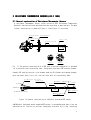
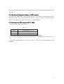
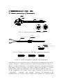
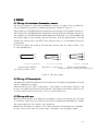
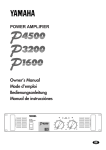
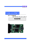
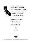
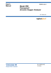
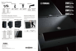
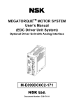
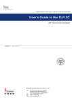
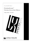
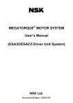
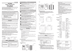
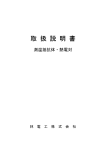
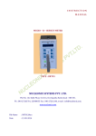
USER’S MANUAL
RESISTANCE THERMOMETER
SENSORS
&
THERMOCOUPLES
HAYASHIDENKO CO., LTD.
Tokyo, JAPAN
Table of Contents
1. BEFORE
BEFORE YOU START
3
2.RESISTANCE THERMOMETER
THERMOMETER SENSORS
6
2.1 General construction of Resistance Thermometer Sensors 6
2.2 Operating Temperature Range of RTD sensors
7
2.3 Tolerance of RTD sensors
7
3.THERMOCOUPLES
3.1
3.2
3.3
3.4
General construction of Thermocouples
Limits of operating temperature
Tolerance of thermocouples on temperature
Extension and/or Compensating cables
4.WIRERING
WIRERING
4.1 Wiring of RTD sensors
4.2 Wiring of thermocouples
4.3 Wiring with care
5. HOW TO HANDLE AND INSTALL SENSORS
5.1 Handling
5.2 Installation
8
8
9
11
12
13
13
13
13
14
14
14
6.HOW TO MEASURE TEMPERATURE CORECTLY
14
7.WARRANTY
15
7.1 Term of warranty
7.2 Range of warranty
7.3 Range of service
15
15
15
2
1. BEFORE YOU START
Before you start to use temperature sensors, please read carefully this user’s manual
and understand how to use temperature sensors correctly. If sensors are handled and/or
treated with misuse, alteration, or abuse, it may cause the serious injuries or damages
to personnel and objects. When you use temperature sensors, be sure to follow the
instruction stated in this manual.
The symbols and meanings used in this user’s manual are as follows. The below is
the classification and explanation of a risk and its degrees occurred by a misuse,
alteration, abuse, or abnormal handling.
!
WARNING
!
CAUTION
“Warning” identifies the conditions and actions that may
pose hazards such as death or serious injury to the user,
when the sensor is misused, abused or abnormally handled.
“Caution” identifies the conditions and actions that may
damage the sensor being used, when it is misused, abused or
abnormally handled.
!
WARNING
● Installing a temperature sensor
・ Extension
thermometer sensor) and compensation
xtension lead wires for RTD(resistance
RTD
compensation cables
cables
for thermocouples should be connected to the terminals of the proper polarity on
a measuring instrument. Do not connect to an AC power supply to prevent overheating
and/or fire risks.
・ Do not handle a temperature sensor violently as it is a sensitive and fragile
device. A human body may be damaged by dropping, etc. Moreover, it may cause
breakage or short circuit inside the sensor and cause an inaccurate temperature
measurement.
・ When install a temperature sensor at a hazardous place such as an explosion-proof
area, precautions must be taken. The terminal head of a explosion-proof type
temperature sensor is certified to use on condition that it should be placed at
ambient temperatures between -20 degrees C to +40 degrees C.
C Please carefully place
the terminal head according to the regulations and/or rules on explosion-proof
equipment after checking the ambient temperature of an installation place for
safety.
・ The explosion-proof packing type cable gland is available in the drawing-in system
of the external lead on a explosion-proof type sensor, and it is necessary to connect
3
an external lead wire by using the specified cable gland when using d2G4
explosion-proof sensors made by Hayashidenko.
● Maintenance
The installation place of a temperature sensor may be mostly exposed extreme
conditions such as high temperature and/or high pressure. It is very dangerous to
immediately start a maintenance work in the process of an operation and just after
the stop of an operation. A maintenance and replacement work should be performed
after checking the stop of an operation and the temperature and pressure become
almost the same as that of the ambient conditions.
A sensor with a ceramic protecting tube may be broken by rapid heating or rapid
cooling. Preheating should be generally needed for the tube.
!
CAUTION
● Installing a sensor
・
When install a sensor with a terminal head, the temperature around the terminal
head should be from room temperature to +60 degrees C and do not install it in
a dusty, dirty, or wet environment.
・ If a part connecting inner leads of a sensor and outer extension lead wires (we
call it “sleeve”) is exposed at high temperature, high humidity, and/or chemical
agents and other, it may cause the degrade of filled epoxy resin inside and the
failure of insulation resistance.
・ When a temperature sensor is fixed on machinery or equipment, generally it is fixed
by using a screw or flange. When a screw is used, sealing tape or sealing agent should
be wrapped on the screw for a JIS R (tapered) screw. And a gasket should be attached
for a JIS G (parallel) screw. When it is installed by a flange, tighten the bolts equally
attaching a specified gasket. If an air-tightness is required, carry out an
air-tightness leak test after installing the sensor.(Figure 1)
・ A Mineral Insulated Metal sheathed RTD or TC sensor can be bent up to 5 times of the
radius of the outer diameter of the metal sheath. But it may cause damage if it is
bent less than 5 times of the radius and returned repeatedly.
・ And a platinum sensing resistor is enclosed in the tip of a MI RTD sensor. So never
bend and give stress on the sensing part from the tip to 100mm long of the sensor
(Figure 2).
4
Figure 1
Figure 2
Gasket
Seal tape
R≧5D
100mm Non bending
φD
MI Metal Sheath
Do not apply excessive stress on lead wires when use a temperature sensor with lead
wires. The connected part of the inner leads and the outer leads and/or the outer
leads themselves may be damaged or broken by outer stress such as excessive pulling
or bending. When attach a flexible tube to protect the outer leads, it may be broken
the engaged part of the flexible tube by excessive stress.
● Storage
・Check the electric continuity and the insulation resistance of a temperature sensor
before storage.
・ Do not store a sensor in a dusty, dirty or wet environment and store it an indoor
and dry place.
・If a sensor is not used for a long period, store it in a PVC plastic bag, etc. with
a drying agent.
● Disposal of a used sensor
・ Do not dispose of a sensor in a landfill. Treat the temperature sensor as an
industrial waste when no longer usable. When it is difficult to throw away it as
an industrial waste, make a contact with a company who can handle the industrial
waste and get permission from a prefectural governor.
● The quality of dust
dust and water proof of a terminal box
・ Sensors with terminal boxes that meet conditions as below are certified to dust
and water proof.
Temperature sensors mounted terminal boxes, type H2, H3, H4, H5, E6,
or E7, and those that [water[water-proof] is stated in number codes.
The state that the lid and conduit valve of a terminal box are accurately closed
prevents the sensor from water and dust.
・ A water and dust proof test is to check under the JIS conditions whether or not
5
water, oil, and/or solid substances break into the inside of a terminal box sealed
the conduit valve off. However, all of the products are not investigated in order
to guarantee the quality of water and dust proof. Therefore, those products are
CORRESPONDENT to the quality of water and dust proof and might not be able to be
operated under any of your environment.
・ In case that the products are under tough conditions and unsuitable installations
for water and dust proof, those cannot keep the quality of water and dust proof.
・ To keep the quality of water proof, we recommend reinstalling an O ring in a year
due to the deterioration of the ring.
6
2 RESISTANCE THERMOMETER
THERMOMETER SENSORS(JIS C 1604)
2.1 General construction of Resistance Thermometer Sensors
A resistance Thermometer Sensor (often called as RTD: Resistance Temperature
Detector) has various forms and constructions according to applications. The most
typical construction is shown as Figure 1.1 and Figure 1.2 as below.
Terminal Head
Fixed Mounting
(Flange)
Terminal Block
Inner leads
Protecting Tube
Pt Element
50
1A
2A
A B b
2B
1B
1b
Single
2b
Double
Fig. 1.1 The general construction of a RTD with a terminal head which is attached
to a stainless steel protecting tube, flange and inserted a CRF sensing element
A model CRF sensing resistor is an element used our CR (Ceramic wire-wound element)
with stainless steel fin to fit into the inner wall of a protecting tube.
Crimp-type
A(RED)
Terninal
Lead wire
MI Metal
Sleeve
Sheath(Ni)
Ni leads
B(WHITE)
(40)
Pt
B(WHITEorBLACK)
Magnesium
MgO
Element
oxide
Figure 1.2 General construction of a Mineral Insulated RTD sensor
A MI(Mineral Insulated) metal sheathed RTD sensor is so manufactured that it has the
construction of flexibility and the integrated structure by filling insulating
7
materials between the protecting tube and the internal connecting wires and sensing
resistor.
2.2
2.2 Operating Temperature Range of RTD sensors
sensors
The operating temperature range of RTD sensors is different from the materials of
protecting tube, the inner structure or style of sensors. Be sure to use the sensor
within the temperature range specified at prearrangement.
2.3 Tolerance of RTD sensors
sensors(JIS C 1604)
Refer to the formula at Table 1-1.
Table 1-1
Class
Tolerance(Unit:℃)
A
±(0.15+0.002|t|)
B
±(0.3+0.005|t|)
Remarks
1.|t| means the values of measured temperature (℃) regardless to the signs of +
or -.
2. JPt 100Ω was abolished in revision of JIS in 1997 due to the conformity to IEC
standard.
8
3 THERMOCOUPLES(JIS
HERMOCOUPLES(JIS C 1602, 1605)
3.1 General construction of Thermocouples
Terminal Head
Terminal
Protecting Tube
Insulator
+
-
1
-
+
-
+
Single
2
Double
Figure 2.1 General construction of Thermocouples
Sleeve
(Epoxi filling)
Compensation lead
Magnesium oxide
TC wires
Measuring Junction
Figure 2.2 General construction of MI Metal Sheathed thermocouples
Ungrounded
Grounded
Exposed
Figure 2.3 Type of the measuring junction of MI thermocouple
A thermocouple with a protecting tube is constructed with thermocouple bare wires,
ceramic insulators, a terminal block and a terminal head as shown at Figure 2.1.
Mineral insulated thermocouple is a thermocouple with such integrated construction
that powdery inorganic insulator (for example, magnesium oxide; MgO) is filled up
between metal sheath and thermocouple wires and sealed as shown at Figure 2.2.
The MI thermocouple can be made 3(three) types of measuring junctions such as
“Ungrounded”, “Grounded,” and “Exposed” junctions. The advantages of MI
thermocouple are (1) thinness, (2)fast response, and (3)bendability---bending radius
9
shall be 5 times of the outer diameter of metal sheath as shown at Figure 2.3.
3.2 Limits of operating temperature
Table2-1 Unit:℃
Diameter
Nornal
Elevated
of
Operating operating
Symbol of Type
element Temperatur Temperatur
Wire
e Limit
e Limit
(mm)
(℃)
(℃)
B
R
S
N
K
0.5
1500
1700
0.5
1400
1600
0.65
1.0
1.6
2.3
3.2
0.65
1.0
1.6
2.3
3.2
0.65
850
950
1050
1100
1200
650
750
850
900
1000
450
900
1000
1100
1150
1250
850
950
1050
1100
1200
500
1.0
500
550
1.6
2.3
3.2
0.65
1.0
1.6
2.3
3.2
0.32
0.65
1.0
1.6
550
600
700
400
450
500
550
600
200
200
250
300
600
750
800
500
550
650
750
750
250
250
300
350
E
J
T
Table2-2 Unit:℃
Sheath O.D.
(mm)
Sheath
Material
Sheath
TC Type
1.0
1.6
3.2
A,B
A,B
4.8
A
6.4
B
A
8.0
B
SK
650
750
800
900
800
1000
SE
650
750
800
900
800
900
750
750
SJ
450
650
350
350
ST
300
350
A: Austenitic stainless steel
B: Corrosion and heat resistance super alloy
* Normal operating temperature limit
A
900
800
B
1050
900
750
350
Table 2-3 Unit:℃
Normal
Elevated
Operating
Operating
Material
temp. limit Temp. Limit
Iron
600
800
SUS304
750
850
Stainless Steel
SUS316
850
950
SUS310S
900
1000
Titanium
400
500
Hastelloy C
1090
1250
Monel
500
600
Inconel
1000
1100
Sandvic P4
1000
1100
Khantal A1
1100
1300
Ceramic tube Type0(PT0)
1600
1850
Ceramic tube Type1(PT1)
1500
1550
Ceramic tube Type2(Pt2)
1400
1550
Si3C4 tube
1400
1600
Table 2-4 Unit:℃
Normal operating
Temperature Limit
Material of Lining & Tube
Glass lining
200
FEP(Teflon) Tube
180
The limits of normal operating temperature and elevated operating temperature are
given in JIS C 1602-1995 “Thermocouples” and JIS C 1605-1995 “Metal Sheathed
Thermocouples”.
10
“Normal operating temperature limit” means the limit of temperature within which
thermocouples can be continuously used in the air. “Elevated operating temperature
limit” means at which thermocouples can be used for a short time in case of unavoidable
needs.
Regarding the normal operating temperature and the elevated operating temperature,
refer to Table 2-1 for thermocouples, Table 2-2 for Metal Sheathed Thermocouples and
Refer to Table 2-3 for the normal operating temperature of protecting tubes.
Moreover refer to Table 2-4 for the normal operating temperature of lining and Teflon
tube.
11
3.3 Tolerances of thermocouples on temperature
Type
B
R, S
N
K
E
J
T
Temperature range
Torerance
Temperature range
Torerance
Former grade*
Temperature range
Torerance
Temperature range
Torerance
Former grade*
Temperature range
Torerance
Temperature range
Torerance
Former grade*
Temperature range
Torerance
Temperature range
Torerance
Former grade*
Temperature range
Torerance
Temperature range
Torerance
Former grade*
Temperature range
Torerance
Temperature range
Torerance
Former grade*
Temperature range
Torerance
Temperature range
Torerance
Former grade*
Table 3
Classification by tolerance(2)
Class 1
Class 2
Class 3
─
─
600℃≦T<800℃
─
─
±4℃
─
600℃≦T<1700℃ 800℃≦T<1700℃
─
±0.0025・|t|
±0.005・|t|
─
─
Grade 0.5
0℃≦T<1100℃(3) 0℃≦T<+600℃
─
±1℃
±1.5℃
─
─
600℃≦T<1600℃
─
─
±0.0025・|t|
─
─
Grade 0.25
─
-40℃≦T<+375℃ -40℃≦T<+333℃ -167℃≦T<+40℃
±1.5℃
±2.5℃
±2.5℃
375℃≦T<1000℃ 333℃≦T<1200℃ -200℃≦T<-167℃
±0.004・|t|
0.0075・|t|
0.015・|t|
─
─
─
-40℃≦T<+375℃ -40℃≦T<+333℃ -167℃≦T<+40℃
±1.5℃
±2.5℃
±2.5℃
375℃≦T<1000℃ 333℃≦T<1200℃ -200℃≦T<-167℃
±0.004・|t|
0.0075・|t|
0.015・|t|
Grade 0.4
Grade 0.75
Grade 1.5
-40℃≦T<+375℃ -40℃≦T<+333℃ -167℃≦T<+40℃
±1.5℃
±2.5℃
±2.5℃
375℃≦T<800℃
333℃≦T<900℃
-200℃≦T<-167℃
±0.004・|t|
0.0075・|t|
0.015・|t|
Grade 0.4
Grade 0.75
Grade 1.5
-40℃≦T<+375℃ -40℃≦T<+333℃
─
±1.5℃
±2.5℃
─
375℃≦T<750℃
333℃≦T<750℃
─
±0.004・|t|
0.0075・|t|
─
Grade 0.4
Grade 0.75
─
-40℃≦T<+125℃ -40℃≦T<+133℃ -67℃≦T<+40℃
±0.5℃
±1℃
±1℃
125℃≦T<350℃
133℃≦T<350℃
-200℃≦T<-67℃
±0.004・|t|
0.0075・|t|
0.015・|t|
Grade 0.4
Grade 0.75
Grade 1.5
Tolerance means allowable maximum of the remainder of the temperature converted
Note(2) from thermoelectromotive force using the table of the reference
thermoelectromotive force substracted by the temperature of measuring junction.
Note(3) Tolerance class 1 of type R and S thermocouples is applicable to standard thermocouples. Re 1. |t|means the value of measured temperature (℃) regardless to the sign of + or -.
Re 2. The mark * means informative reference.
The tolerances are classified in each type of thermocouples as shown in Table 3.
12
3.4 Extension and/or Compensating cables
Extension and/or compensating cable is identified with color according to the type
of thermocouples and have nearly the same thermoelectromotive force characteristic
as the thermocouple which is to be used in combination.
Tolerance of compensating cable is determined as Table 4 according to the temperature
of connecting junction with thermocouple.
When wiring thermocouples, be sure to use the proper compensating cables. If the
unproper cable such as the cable for a different type of thermocouple or copper lead
wires are used, it will generate the unproper EMF and will not be able to expect the
accurate measurement.
Be sure to keep the temperature of compensating junction properly at connecting point
with thermocouple and compensating cable.
Former
Synb symbol
Type of TC
ol (refere
nce)
B
R
S
N
BC
RCA
RCB
SCA
SCB
BX
J
Color
(Class2)
Gray
Gray
RX
Orange
Black
SX
SX-G
─
±60
0~+200℃
SX-H
±60
±100
-25~+200℃
─
±100
0~+150℃
KCA
─
─
±100
0~+150℃
Blue
KCB
WX
─
±100
0~+150℃
KCC
VX
─
±100
0~+100℃
EX
EX
±120
±200
-25~+200℃
Yellow
0~150℃
RX-H
0~+100℃
-25~+200℃
Black
+3
-7
0~+200℃
±30
±100
JX
─
±60
±60
JX
─
─
KX
Purple
BX-G
─
KX
Amethyst
Temperature of
compensating
junction(℃)
RX-G
─
Green
Tolerance
(℃)
0~+100℃
─
─
Symbol
±30
NC
Pink
JIISC1610-1981(旧JIS)
─
NX
K
E
Color
(Class1)
Table 4
Tolerance(μV) Temperature
of
compensatin
Class1 Class2
g
junction(℃
─
─
0~+100℃
±85
±140
-25~+200℃
KX-G
KX-H
KX-GS
KX-HS
WX-G
WX-H
VX-G
TX
TX
Brown
Brown
±30
±60
-25~+100℃
±1.5
-20~150℃
±3.0
±2.5
-20~100℃
EX-G
EX-H
JX-G
±2.5
JX-H
TX-G
T
±2.5
TX-H
TX-GS
TX-HS
-20~150℃
±2.0
±1.0
* Hayashidenko has the extension cables corresponding to JIS C 1610-1995(former JIS) as standard stock
for the time being.
* The goods corresponding to new JIS C 1610-1995 are made-to-order.
* Color of porality: +(plus) the same color with overall, -(minus) White for Class 1.
13
4 WIRING
4.1 Wiring of resistance thermometer sensors
The wiring system of resistance thermometer sensors includes 2-wire conducting,
3-wire conducting and 4-wire conducting system as shown at Figure 3.1,
The terminal A of the RTD should be connected to the terminal A of the measuring device.
The terminal B of the RTD should be connected to the terminal B of the measuring device.
The terminal b of the RTD should be connected to the terminal B, b or C of the measuring
device(The name of the terminal may be different from the manufactures).You may
connect the terminal B of the RTD to the terminal b(B or C) of the measuring device
to whichever.
Be sure to tighten the screw of the terminals and use care for short by dust, dirt
or foreign materials.
A
S
S
B
2 wire system
Not expect accrate measurment
due to adding resistance of leads
A
A
B
B
A
B
B
3 wire system
S
4 wire system
Most general for industrial use
Suitable to accurate measurment
by measuring potential difference using constant current
Figure 3.1 Wiring system
4.2 Wiring of Thermocouples
Thermocouples should be connected to the terminals of a measuring equipment by using
special compensating cables.
Check the polarity of plus(+) and minus(-) and connect to the proper terminal, and
be sure to tighten the screw of the terminals. And connect the cables carefully not
to occur short-curcuiting by dust, dirt or foreign materials.
4.3
4.3 Wiring with care
When wiring the sensor to a measuring instrument, be sure to take care as the type
of extension lead wires are perfectly different from RTD and thermocouples. Choose
the proper materials for overall and lead wires.
Connect the terminals of sensor to the input terminals of the measuring instrument.
Be sure to wire the cable of sensor apart from power line and power supply.
14
5 HOW TO HANDLE AND INSTALL SENSORS
5.1 Handling
・When it seems that the sensor fail to operate properly, do not decompose the sensor
and contact us first.
・ Do not apply the sensor with vibration and shock in handling or transportation.
Especially handle the sensor with ceramic protecting tube with special care as
it is easily broken.
・ The minimum bending radius of metal sheathed thermocouple shall be 5 times of the
outer diameter of metal sheath. The minimum bending length of metal sheathed RTD
sensor shall be more than 100 mm from the tip of the sensor.
5.2. Installation
・ Check the polarity of the terminals and connect the sensor properly.
・ Keep the temperature of terminal head and sleeve at 60 degrees C or below. Install
the sensor to the place without water and moisture.
・ To prevent the influence of noise, install the lead wire apart from the power line
with high voltage and high current. Do not install the compensating wire parallel
to or together with the power line. The wire with shield could expect the efficiency
of preventing the electric noise.
・ Install the compensating wire apart from the noise source such as high frequency
wave and microwave.
・ Be sure to keep properly the temperature of compensating junction with
thermocouple(see Table 2-2). If it will exceed the temperature shown, measuring
error would be greater than that.
6 HOW TO MEASURE THE TEMPERATURE CORRECTLY
The measuring junction of a thermocouple and the sensing resistor of a RTD should
be needed to equal thermally to the measuring object. So it is essential to have the
insertion length sufficiently.
The insertion length may differ depending on the measuring condition but the following
shows the insertion length at the magnify of the outer diameter of protecting tube
as a guide.
Wall of furnese
10 times
15 times
MI RTD
10 times
15 times
TC M
( eta l)
15 to 20 times
TC (Nonmeta l)
15 to 20 times
Insertion Length
inside of furnese
Erro of
temperature
Protecling Tube
MI RTD
O.D.of
Still air
Differeuce of
temperation
Still water
Type
15
7 WARRANTY
7.1 Term of warranty
1(one) year from the date of shipment at Hayashidenko
7.2 Range of warranty
Warranty is limited to the fault of the products by the cause on Hayashidenko.
If it is clear that the failure is occurred by our fault, we will repair or exchange
the products under our responsibility.
But we will except from the guarantee if it corresponds to the following items.
① If it based on unsuitable condition, environment, handling, use, etc. except
having been checked by our catalog, or the specifications written separately
② If the cause of failure is based on reasons other than manufacturers
③ The failure based on decomposition, reconstruction, repair, inspection, etc.
by other company without our permission.
④ The failure based on the use of the goods without original method to use
⑤ The failure based on the reason which was not able to be foreseen with the
level of the science and technology at the shipment from our company
⑥In addition, the failure based on causes which are not responsible for our
company, such as accident and disaster
"A guarantee" means the guarantee only for the goods supplied. The guarantee of the
damage induced by failure of the goods will be taken as exemption from responsibility.
7.3 Range of service
Please notice that the following service like dispatch of a technician is not included
the price of sensors.
1. Training and/or joint servey or inspection on site
2. Maintenance and adjustment and repair
3. Instruction and education for sensor technique
4. Special test and inspection at the condition specified by customer
Please consult Hayashidenko or our distributors separately when the above services
are required.
* The manual is subjected to change without notice.
16
HAYASHIDENKO CO., LTD
ISO9001 accredited and ISO14001 accredited
URL :
http://www.hayashidenko.co.jp
Head office & Tokyo Sales office:
office: 6-5-5, Honkomagome, Bunkyo-Ku, Tokyo 113-0021 Japan
TEL03-3945-3151 FAX03-3945-3130
Osaka Sales Office: Hanahara No. 8 Bld, 6-8-8 Nisi-Nakajima, Yodogawa-Ku, Osaka
532-0011
TEL06-6885-4801 FAX06-6885-4825
Shizuoka
Shizu
oka Sales Office: 16-3, Ejiridai-Machi Shimizu-Ku, Shizuoka
TEL0543-64-9460 FAX0543-67-4046
Issued in June, 2005
MaS01E-1B
17
18