1
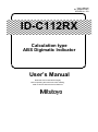
User’s Manual
No. 99MAH034B1
SERIES No. 543
ID-C112RX
Calculation type
ABS Digimatic Indicator
User’s Manual
Read this User’s Manual thoroughly
before operating the instrument. After reading,
retain it close at hand for future reference.
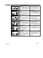
CONVENTIONS USED IN THIS MANUAL
Safety Precautions
To ensure that instruments are operated correctly and safely, Mitutoyo manuals use
various safety symbols (Signal Words and Safety Alert Symbols) to identify and warn
against hazards and potential accidents.
The following signs indicate general warnings:
WARNING
Indicates a potentially hazardous situation which, if not avoided, could result in serious
injury or death.
Types of Notes
The following types of notes are used in this manual to help the operator obtain reliable
measurement data through correct instrument operation.
An important note provides information essential to use the product. You cannot
IMPORTANT disregard this note.
An important note is a type of precaution, which if neglected could result in degraded
performance or accuracy, or instrument malfunction/failure.
NOTE
A note provides information to be especially noted or supplemented to use the product.
A note also supplies information to be noted for specific operations.
TIP
A tip is a type of note that helps the user apply the techniques and procedures described
in the text to his or her specific needs.
It also provides reference information associated with the topic being discussed.
The specifications and information in this manual are subject to change without notice.
Copyright 2014 Mitutoyo Corporation.
No. 99MAH034B
All rights reserved.
i
Battery-related Warnings
WARNING
If the battery is misused or abused, leakage or, in extreme causes, explosion and/or fire
can result. Observe the following precautions to avoid instrument failure or malfunction.
Do not disassemble, deform, short-circuit, charge, or heat the battery to 100°C or over,
or throw the battery into a fire.
Always insert the battery correctly with regard to the polarities (+ and –) marked on the
battery and the instrument.
Always use the recommended battery.
If the instrument will not be used for more than three months, remove the battery and
store it separately.
When discarding or storing the battery, cover the positive (+) and negative (–) terminals
with insulating tape to prevent contact with other metals. When disposing of it, follow
the ordinances or regulations of the local government.
Keep the battery away from direct sunlight, high temperature, high humidity and out of
the reach of children.
Do not swallow the battery. If swallowed, consult a physician immediately.
Should the content contact an eye or skin, or enter the mouth, rinse with water
immediately and consult a physician. Should it adhere to clothing, wash the clothing
with water.
Disposal Warnings
WARNING
ii
A liquid crystal display and a lithium metal battery are used in this product. When
disposing of the instrument, follow the ordinances or regulations of the local
government.
The liquid crystal display contains an irritating substance. Should the liquid content
contact an eye or skin, flush with clean, flowing water. If the substance enters the
mouth, immediately rinse the mouth, drink plenty of water, induce vomiting, and then
consult a physician.
No. 99MAH034B
Cautions on use
Observe the following precautions to avoid instrument failure or malfunction.
Do not strike the instrument or allow it to be struck.
IMPORTANT Do not drop it or apply excessive force to it.
Do not disassemble or modify the instrument.
Do not press the keys with a pointed object (such as screwdriver or ballpoint pen).
Do not use or store the instrument under direct sunlight, or in an excessively hot or
cold environment.
Be alert for malfunction due to material deterioration if it is used in an environment with
low or high atmospheric pressure.
Do not store the instrument in a high-humidity environment. Do not use the instrument
where it could be splashed with coolant.
Do not use high-voltage equipment, such as an electric marking pen, near the
instrument. Electronic parts may be damaged by such equipment. Be alert for
malfunction if it is used in the vicinity of electric noise.
Secure the instrument with a fixture such as a dial gage stand in a vibration-free
environment.
Do not subject the spindle to a vertical load or torsion.
Wipe stains from the instrument panel by using a soft cloth or a cotton swab that is dry
or moistened with diluted neutral detergent. Do not use an organic solvent such as
thinner and benzene, which may cause the instrument panel to deform or malfunction.
The contaminated spindle may cause malfunction. Wipe them off with a cloth damped
with alcohol.
NOTE
No. 99MAH034B
Be alert for measurement errors caused by thermal expansion of the component parts
and the fixtures, resulting from a significant temperature fluctuation. Use the instrument
in a temperature-controlled room that has minimum temperature fluctuation. Allow
sufficient time for the instrument to thermally stabilize if it is moved to an environment
with a different temperature.
iii
Warranty
In the event that this product should prove defective in workmanship or material, within
one year from the date of original purchase for use, it will be repaired or replaced, at
Mitutoyo’s option, free of charge upon its prepaid return to Mitutoyo
If the product fails or is damaged for any of the following reasons, it will be subject to a
repair charge, even if it is still under warranty.
(a) Failure or damage owing to fair wear and tear.
(b) Failure or damage owing to inappropriate handling, maintenance or repair, or to
unauthorized modification.
(c) Failure or damage owing to transport, dropping, or relocation of the instrument after
purchase.
(d) Failure or damage owing to fire, salt, gas, abnormal voltage, lightning surge, or
natural disaster.
(e) Failure or damage owing to use in combination with hardware or software other than
those designated or permitted by Mitutoyo.
(f) Failure or damage owing to use in ultra-hazardous activities.
This warranty is effective only where the instrument is properly installed and operated in
conformance with the instructions in this manual within the original country of the
installation.
EXCEPT AS SPECIFIED IN THIS WARRANTY, ALL EXPRESS OR IMPLIED
CONDITIONS, REPRESENTATIONS, AND WARRANTIES OF ANY NATURE
WHATSOEVER INCLUDING, WITHOUT LIMITATION, ANY IMPLIED WARRANTY OF
MERCHANTABILITY, FITNESS FOR A PARTICULAR PURPOSE, NONINFRINGEMENT
OR WARRANTY ARISING FROM A COURSE OF DEALING, USAGE, OR TRADE
PRACTICE, ARE HEREBY EXCLUDED TO THE MAXIMUM EXTENT ALLOWED BY
APPLICABLE LAW.
You assume all responsibility for all results arising out of its selection of this product to
achieve its intended results.
Export Control Compliance
This Product falls into the Catch-All-Controlled Goods and/or Catch-All-Controlled
Technologies (including Programs) under Category 16 of Appended Table 1 of Export
Trade Control Order or under Category 16 of Appended Table of Foreign Exchange
Control Order, based on Foreign Exchange and Foreign Trade Law of Japan.
If you intend re-exporting the product from a country other than Japan, re-selling the
product in a country other than Japan, or re-providing the technology (including program),
you shall observe the regulations of your country.
iv
No. 99MAH034B
Contents
CONVENTIONS USED IN THIS MANUAL .........................................................................................................i
Battery-related Warnings .................................................................................................................................ii
Disposal Warnings ...........................................................................................................................................ii
Cautions on use ...............................................................................................................................................iii
Warranty ...........................................................................................................................................................iv
Export Control Compliance ............................................................................................................................iv
1
2
3
OVERVIEW ............................................................................................................................................ 1-1
1.1
Overview ........................................................................................................................................ 1-1
1.2
Features(what you can do) ........................................................................................................... 1-2
1.3
Part Name and Dimensions .......................................................................................................... 1-3
1.4
Details of the Display unit ............................................................................................................ 1-4
1.5
Specifications ................................................................................................................................ 1-5
1.6
Standard accessories ................................................................................................................... 1-6
1.7
Optional accessories .................................................................................................................... 1-3
SETUP.................................................................................................................................................... 2-1
2.1
Installation (replacement) of Battery and Initial Setting ............................................................ 2-1
2.2
Adjusting Display Angle ............................................................................................................... 2-2
2.3
Securing Anstrument .................................................................................................................... 2-2
2.4
Mounting Lifting Lever.................................................................................................................. 2-3
2.5
Mounting Lifting Knob .................................................................................................................. 2-4
2.6
Mounting Lifting Release.............................................................................................................. 2-5
2.7
Replacing Contact Point ............................................................................................................... 2-5
FUNCTIONS AND OPERATIONS ......................................................................................................... 3-1
3.1
Power ON/OFF ............................................................................................................................... 3-1
3.2
Measurement mode ....................................................................................................................... 3-2
3.2.1
Origin point setting (Calculation reference point) ............................................................. 3-2
3.2.2
Preset setting ......................................................................................................................... 3-4
3.2.3
Numerical value Editing ........................................................................................................ 3-6
3.2.4
Switching measuring system (ABS/INC) ............................................................................. 3-8
3.2.5
Zero-setting display value .................................................................................................... 3-8
No. 99MAH034B
v
3.2.6
Changing to peak detection mode ....................................................................................... 3-9
3.2.6.1
Run-out detection mode “TIR” ........................................................................................ 3-10
3.2.6.2
Maximum value detection mode “Max”........................................................................... 3-10
3.2.6.3
Minimum value detection mode “Min” ............................................................................. 3-10
3.2.7
Holding display value (when a data processor is not connected) .................................. 3-12
3.2.8
Display value output (when a data processor is connected) .......................................... 3-12
3.2.9
Centering pointer of analog bar ......................................................................................... 3-12
3.2.10
Swtching units (in/mm) ....................................................................................................... 3-12
3.2
Setup mode .................................................................................................................................. 3-13
3.3.1
TOL:Tolerance judgment ..................................................................................................... 3-16
3.3.2
RES:Resolution .................................................................................................................... 3-18
3.3.3
CALC:Calculation function ................................................................................................. 3-20
3.3.4
SCALE:Analog bar graduation ........................................................................................... 3-22
3.3.5
LOCK:Keylock ...................................................................................................................... 3-24
3.3.6
OTHER:Other functions ...................................................................................................... 3-26
3.3.6.1
PC(1):PC communication ............................................................................................... 3-29
3.3.6.2
UNIT(2):Unit display ....................................................................................................... 3-32
3.3.6.3
OFFSET(3):Origin offset ................................................................................................. 3-34
3.3.6.4
RULER(4):Analog bar display ........................................................................................ 3-36
3.3.6.5
FAST(5):Fast measurement frequency .......................................................................... 3-38
3.3.6.6
RESET(6):All reset ......................................................................................................... 3-40
3.2
Calibration mode ......................................................................................................................... 3-42
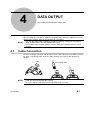
4
DATA OUTPUT ....................................................................................................................................... 4-1
4.1
Cable connection ........................................................................................................................... 4-1
4.2
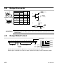
Output connector .......................................................................................................................... 4-2
4.3
Output Data Format ....................................................................................................................... 4-2
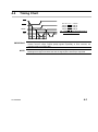
4.4
Timing Chart ................................................................................................................................... 4-3
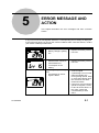
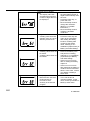
5
ERROR MESSAGE AND ACTION ........................................................................................................ 5-1
Service Network
vi
No. 99MAH034B
1
1
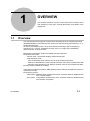
OVERVIEW
This chapter describes overview of this instrument including names
and functions of each part, external dimensions, and details of the
display unit.
1.1
Overview
This special instrument supports measurements described in the accompanying manual
(No.99MAH035B) by calculation function which uses the formula f(x)=Ax+B+Cx (“x” is a
spindle displacement)
To use the calculation function, set up this instrument referring to the accompanying
manual and "3.3.3 CALC: Calculation function" and "3.2.1 Origin point (Calculation
reference point)" in this document.
Measurement and Setup mode are available with this instrument.
Measurement mode
・Normal mode : Dynamically displays measurement data
・Peak detection mode :
・Run-out detection mode: Detects run-out of the measurement data
・Maximum value detection mode: Detects maximum value of the measurement data
・Minimum value detection mode: Detects minimum value of the measurement data
Setup mode: Enables each setting
There are two measuring systems, ABS (Preset) system and INC (Comparison) system in
measurement mode.
Measuring system
・ABS system: Absolute value measurement which measures distance (displacement)
from a preset position .
・INC system: Comparative measurement which measures distance (displacement)
from the zero-set position .
No. 99MAH034B
1-1
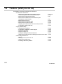
1.2
Features (what you can do)
The following can be achieved with this instrument:
・Measurement-related items
・Measurement after setting the calculation formula
・Tolerance judgment of the measurement result
・Measurement in the absolute system
・Measurement of distance from the reference point
(Comparative measurement)
・Measurement of run-out
・Measurement of maximum value
・Measurement of minimum value
・Outputting the measurement data to the data processor
・Changing the display value unit
・Display-related settings
・Changing the resolution
・Changing the graduation of the analog bar
・Hiding the unit display
・Hiding the analog bar
・Holding the displayed measurement data
・Setting up the center point of the analog bar as the current value
・Other setting-related items
・Key lock
・Setting up each function from PC
・Setting up the FAST mode
・Resetting to the factory default
1-2
P.3-2,3-20
P.3-16
P.3-8
P.3-8
P.3-10
P.3-10
P.3-10
P.3-11
P.3-12
P.3-18
P.3-22
P.3-32
P.3-36
P.3-11
P.3-12
P.3-24
P.3-29
P.3-38
P.3-40
No. 99MAH034B
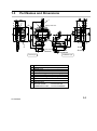
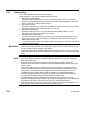
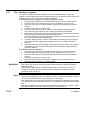
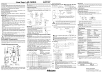
1.3
Part Names and Dimensions
1
6
5
5
2
3
6
Display rotate 330°
(A)
(B)
8
4
9
Joint screw
M2.5x0.45
ISO/JIS type
1
2
3
4
5
6
7
8
9
10
No. 99MAH034B
7
Joint screw
No.4-48 UNF
10
ASME/AGD type
Cap
Output connector (with rubber cap)
Display unit
Battery holder
Lever mounting position (left and right)
Flat back
Release mounting hole (with cap)
Stem
Spindle
Contact point
ISO/JIS models
: Part No.901312
ASME/AGD models : Part No.21BZB005
1-3
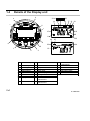
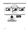
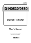
1.4
Details of the Display unit
4
5
20
19
14
7
16
21 17 12 18
6
7
15
10
9
11
26
22
25
8
8
24
23
6
13
1
3
2
1-4
1
Lower left key
11
Data hold
21
2
3
4
5
6
7
8
9
Center key
Lower right key
Upper right key
Upper left key
Key assist
Cursor
Parameter
Display value
12
13
14
15
16
17
18
19
22
23
24
25
26
10
Unit
20
Preset No.
Comparative measurement
Calculation formula
Origin offset
Tolerance judgment
Analog bar
Analog bar graduation
Minimum value detection
measurement
Run-out detection
measurement
Maximum value detection
measurement
Lock
Lower over-range
Upper over-range
Low battery alarm
FAST
No. 99MAH034B
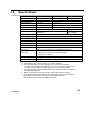
1.5
Specifications
Model name *1
Order No. *1
Resolution *2
Measuring range
Overall *3
Hysteresis *3
Repeatability *3
Stem diameter
Contact point
Measuring force
Measuring direction
Protection level *4
Power supply
Battery life *5
Scale
Response speed
Measurement
frequency *6
CE marking
ID-C112RXB
543-340B
0.001 mm
12.7 mm
Within 0.003 mm
Within 0.002 mm
Within 0.002 mm
φ8 mm
ID-C112RMXB
ID-C112REXB
543-341B
543-342B
.00005 “/0.001 mm
.5 “/12.7 mm
Within ±.0001 “/0.003 mm
Within .0001 “/0.002 mm
Within .0001 “/0.002 mm
3/8 “ DIA
Carbide
(No.4-48UNF)
Carbide
(M2.5x0.45)
≤1.5 N
Useful in all directions
IP42 (in factory shipment state)
Lithium battery CR2032 ×1pc.
Normal use :Approx. 1 year
Electrostatic capacitance absolute encoder
Infinite
Normal mode, Peak detection mode(FAST mode enabled):10 times/sec
Peak detection mode(FAST mode disabled):50 times/sec
EMC Directive: EN61326-1
Immunity test requirements: Clause 6.2 Table 2
Emission limit: Class B
0 ℃~40 ℃
-10 ℃~60 ℃
Operating temperature
Storage temperature
Net weight
170 g
*1:All instruments in this series are of the flat-back type.
*2:Changeable by way of setting. Refer to “3.3.2 RES : Resolution”.
*3:20°C, normal measurement, the quantizing error (±1 count) is not included
The values are calculated with coefficients; A=1, B=0, C=0, and the resolution set to
0.001mm. They are subject to change depending on the coefficient settings.
*4:The protection level (IP: International Protection) is indicated according to IEC 60529
and JIS C 0920 standards.
*5:Battery life depends on use of the indicator. Use the above value as a guide.
*6:If the spindle speed exceeds following, the correct peak value may not be displayed.
Normal mode, Peak detection mode (FAST mode enabled):10µm/sec
Peak detection mode (FAST mode disabled):50µm/sec
No. 99MAH034B
1-5
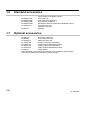
1.6
Standard accessories
・
・
・
・
・
・
・
・
1.7
No.WA100
Lithium battery CR2032(for monitor)
User’s Manual
User’s Manual (supplement)
Quick Reference Manual
EU Batteries Directive /EMC Directive/WEEE manual
Precautions for Use
Inspection certificate
Warranty
Optional accessories
・
・
・
・
・
・
・
・
・
・
1-6
No.99MAH034B
No.99MAH035B
No.99MAH036B
No.99MAH042M
No.421RAC717
No.905338
Connecting cable(1m)
No.905409
Connecting cable (2m)
No.21EZA313
Parameter Setup Kit
No.21EZA198
Lifting lever(for ISO/JIS models)
No.21EZA199
Lifting lever(for ASME/AGD models)
No.21EZA105
Lifting knob(for ISO/JIS models)
No.21EZA150
Lifting knob(for ASME/AGD models)
No.540774
Lifting release
Interchangeable contact points and extension rods for Mitutoyo dial indicators
Color caps for Mitutoyo dial indicators (waterproof type)
No. 99MAH034B
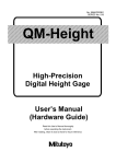
2
2.1
2
SETUP
This chapter describes installation of a battery, how to mount the
stand or jigs, and the accessory replacement procedure.
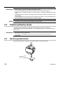
Installation (replacement) of Battery and Initial
Setting
A lithium battery (CR2032) is used with this instrument.
This instrument is not delivered with the battery set into position, so set the battery before
use.
1. Remove the battery holder by using a flat-blade screwdriver or the like.
(When replacing the battery, remove the spent battery.)
2. Set the battery into the battery holder as described in the figure below.
3. Set the battery holder into the original position. ([------] is displayed.)
4. To enter into the preset setting, press the center key.
5. Set up the preset values referring to "3.2.2 Preset setting".
6. Set up measurement mode and function which you want. (See section 3. Functions
and Operating Procedure.)
(2)
(3)
No. 99MAH034B
2-1
IMPORTANT
NOTES
2.2
・ Do not use a sharp-pointed tool to remove the battery holder and not pry out the
battery holder, to prevent damage to the battery holder.
・ Note not to damage your nail when the battery holder is removed by hand.
・ If the battery and battery holder is not set properly, a damage andmalfunction may
result.
・ If the Measurement mode is not entered after executing the above procedure, set the
battery again.
・ If the instrument will not be used for more than three months, remove the battery and
store it separately to prevent damage by battery leakage.
・ The supplied battery is used only to check the functions and performance of the
instrument, so it may not meet the battery life specification.
Adjusting Display Angle
The display can be rotated 90° (to position A) clockwise or 240° (to position B)
counterclockwise from the initial position. (For the rotating range, see 1. Part Names and
Dimensions.)
IMPORTANT
2.3
・ Stoppers are set at both positions A and B. Stop rotating the display at the stoppers, or
the instrument may malfunction.
・ Do not push in the display or pull it out. Doing so may cause the instrument to
malfunction.
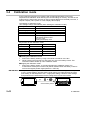
Securing Instrument
Secure the instrument to a stand, or fix it with a fixture or jig, when using it.
+0.02
φ8(9.52) +0.005
2-2
No. 99MAH034B
IMPORTANT
・ Avoid using a lock screw to fix the stem directly. If fixed under a clamping torque of 150
N・cm or greater, the spindle may not move smoothly.
NOTES
・ Set up the instrument with the spindle perpendicular to the reference plane or the
surface to be measured. If the spindle axis is not perpendicular to the reference plane
(measured surface), measurement errors will result.
→If the spindle axis is inclined ϕ from the perpendicular line to the reference plane,
measurement error δ will be as follows for the measured length of 12 mm:
ϕ = 1°: δ = 0.002mm
ϕ = 2°: δ = 0.007mm
ϕ = 3°: δ = 0.016mm
・ If the instrument is to be secured with a fixture, fix it by the stem in a slotted hole of
about ø8G7 (+0.005 to +0.02) or ø9.52 (+0.005 to +0.02).
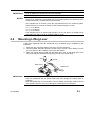
2.4
Mounting Lifting Lever
A lifting lever (optional/ Parts No. 21EZA198 (mm), 21EZA199 (in)) is available for this
instrument.
1. Rotate the cap counterclockwise to remove it from the instrument.
2. Hold the spindle with pliers protecting it with a rag to prevent it from rotating, remove
the screw (M2.5 or No.4-48UNF) at the top of the spindle.
3. Attach the spindle stop provided with the lifting lever. Next, fix the lifting lever to the
lever mounting part (dovetail) while applying its top to the spindle stop.
Cap
Screw
Stop screw
Lifting Lever
IMPORTANT ・ Store the removed screw and cap, taking care to prevent loss.
・ Using this instrument with the spindle stop loose may damage the internal parts or
workpiece.
・ When the spindle stop is not mounted, be sure to attach the removed screw to the top
of the spindle. Failure to do so may damage the internal parts or workpiece.
No. 99MAH034B
2-3
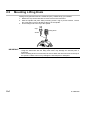
2.5
Mounting Lifting Knob
A lifting knob (optional/ Parts No. 21EZA105 (mm), 21EZA150 (in)) is available.
1. Rotate the cap counterclockwise to remove it from the instrument.
2. Hold the spindle with pliers while protecting it with a rag to prevent rotation, remove
the screw (M2.5 or No.4-48UNF) at the top of the spindle.
3. Fix the lifting knob to the top of the spindle.
Cap
Lifting knob
Screw
・ Store the removed screw and cap, taking care to prevent loss.
IMPORTANT ・ Using this instrument with the lifting knob loose may damage the internal parts or
workpiece.
・ When the lifting knob is not mounted, be sure to attach the removed screw to the top of
the spindle. Failure to do so may damage the internal parts or workpiece.
2-4
No. 99MAH034B
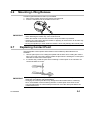
2.6
Mounting Lifting Release
A release (optional/Parts No.540774) is available.
1. Remove the rubber cap from the release mounting hole.
2. Insert the release as far as possible into the hole.
・ Store the removed rubber cap, taking care to prevent loss.
IMPORTANT ・ When attaching the rubber cap, screw it into the hole.
・ When the release is not mounted, be sure to keep the rubber cap inserted.
・ Inserting any object other than the release or applying an excess force to the hole may
cause instrument malfunction.
・ Moving the spindle up or down while the release is loose may damage the internal parts.
2.7
Replacing Contact Point
Interchangeable contact points and extension rods for Mitutoyo dial indicators are
available.
1. Use two pliers (One is for holding the spindle and the other is for holding the contact
point.) and a rag in the figure below. Rotate the plier which is holding the contact point
clockwise to remove the contact point.
2. In a similar way, rotate the plier which is holding a contact point or an extension rod
counterclockwise to mount.
IMPORTANT
No. 99MAH034B
・ When replacing the contact point hold the spindle and turn the contact point.
Otherwise, the indicator may be damaged.
・ Changing the contact point also may change the external dimensions, measuring
force, and limitation of the measuring direction. Contact point errors such as the
non-perpendicularity of a flat contact point and run-out of the roller point add to the
measurement error.
2-5
MEMO
2-6
No. 99MAH034B
3
3
FUNCTIONS AND
OPERATIONS
This chapter describes functions and their operations of this instrument.
Each key function will change as follows depending on the operation mode.
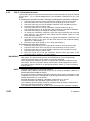
●Measurement mode
* "Press and hold" means pressing and holding the key for 2 seconds or more.
Keys
Press
Press and hold
Lower left
PEAK (3.2.6)
PRESET (3.2.2)
START (3.2.6)
Center
ABS (3.2.4)
ZERO (3.2.5)
DATA (3.2.8)
Lower right
in/mm (3.2.10)
HOLD (3.2.7)
Upper left
ON/OFF (3.1)
(3.2.9)
Upper right
MENU (3.3)
ORIGIN (3.2.1)
●Setup mode/Numerical values setting
Keys
Lower left
Center
Lower right
Upper left
Upper right
3.1
Press
SELECT /
OK /
EDIT/
CANCEL
EXIT
Press and hold
-
-
-
-
-
Power ON/OFF
Power ON: Press the upper left key.
Power OFF: Press and hold the upper left key
NOTE
No. 99MAH034B
・ If the power is turned off right after the battery is installed before completing preset
setting, "------" will be displayed when the power is turned on again.
・ When the power is turned off while the instrument is holding the display value, and
then the power is turned on again, the held display value will be released.
3-1
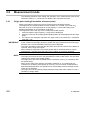
3.2
Measurement mode
The following describes each setting and operation of the measurement mode of this
instrument. Refer to "1.1 Overview" for details of the measurement mode.
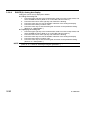
3.2.1
Origin point setting(Calculation reference point)
Origin point setting is required in order to measure using calculation function.
The origin point is a spindle position at which variable "x" in formula : f(x)=Ax+B+Cx
becomes "0" (x=0). If the origin point is not set properly, a correct value may not be
displayed depending on the calculation coefficients.
The origin point can be set only in the normal mode of ABS system.
1. Press and hold the upper right key. ("origin" will be displayed)
2. Press the center key at the appropriate spindle position (to be designated as the origin
point).
3. The value to be displayed right after the origin point is set should be a calculation
result with "x=0".
・ This instrument internally calculates assuming spindle displacement as variable "x”
IMPORTANT
which is based on the origin point(x=0). Unless the origin point that meets various jigs
has been set, a correct calculation result may not be displayed.
・ The origin point will be held even after the power is turned off. However, if the battery is
replaced, set the origin point again.
・ When setting the origin point, the preset position will be cleared (Preset No. will be
disappeared.). However the preset value can be called, as it is being registered.
・ If calculation function is not required, this setting is not necessary.
NOTE ・ The origin point cannot be set in the peak detection mode or INC system. So set it after
changing the normal mode of ABS system.
・ The origin point cannot be completed while the spindle is moving. So complete it after
the spindle stops.
・ When set the origin point while the calculation coefficient “C” is not being set to 0,
overflow error of display value (Err30) is occurring. It is not unusual. A measurement
data will be displayed when the spindle moves and the data will be in the digit number
which can be displayed.
・ The origin point can be offset by setting a desired origin offset value. Refer to "3.3.6.3
OFFSET(3): Origin offset".
3-2
No. 99MAH034B
Origin point setting
OK
(1)
Example of origin point setting
No. 99MAH034B
ORIGIN
(2)
(When calculation coefficient “C”
is not being set to 0.)
3-3
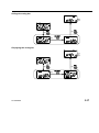
3.2.2
Preset setting
Set up the preset when performing master setting.
Three settings; P1, P2, P3 are available as preset values.
1. Starting the preset setting
Press and hold the lower left key in the measurement mode. "P□" (□ indicates
Preset No.) starts blinking and the previously set value will be displayed. If the value
does not need to be changed, skip to step 4.
2. Selecting preset No.
Press the lower left key and select the preset No. to be set. Pressing the lower left key,
the display changes in the following order: P1→P2→P3.
3. Editing the preset value.
Press the lower right key to move the numerical value editing. Refer to "3.2.3
Numerical value editing" for details of the setting.
4. Completing the preset setting
Lift up the spindle and position the contact point in the desired preset position. Next,
press the center key. The preset setting is completed and the measurement in the
ABS system will be ready.
In the peak detection mode, the spindle position of maximum or minimum value will be
set as the preset position.
・ Repeatability in the range of 0.2 mm (.0079”) from the bottom of the stroke is not
IMPORTANT
guaranteed for this indicator. When setting the origin, be sure to lift the spindle at least
0.2 mm (.0079”) from the bottom of the stroke.
・ The preset value will be calculated automatically according to the unit or the resolution.
Check the preset value when the resolution is changed since the conversion error may
occur.
・ Press the upper left key to cancel the setting,
NOTE ・ The preset setting cannot be completed while the spindle is moving. So complete it
after the spindle stops.
・ The setup preset values and position will be held after the power is turned off.
However, when the battery is replaced, the preset position will be cleared. Set up the
position again.
・ The power supply cannot be turned off with the upper left key in the preset setting.
・ The preset setting may not be completed, when the calculation coefficient “C” is not
being set to 0 and Overflow error of display value (Err30) is occurring. If it occurs,
complete the preset setting after moving the spindle to an appropriate position.
・ The preset setting cannot be completed if Overflow error of preset value (Err95) is
occurring for the selected preset number. Reset the preset value.
・ A rubber damper has been attached to the spindle in this indicator as a shock
absorber. The elasticity of the damper may cause the indicated value to not stabilize at
the bottom of the stroke, but this will not cause any operational problems.
・ Also, the spindle may feel heavy at the bottom of the stroke when this indicator is first
used, but this can be resolved by pushing the spindle up once.
3-4
No. 99MAH034B
Preset setting (Master setting)
Measurement mode
OK
PRESET
(1)
※Press and hold
(4)
SELECT
P1P2P3
SELECT
(2)
P1P2P3
EDIT
(2)
SELECT
P1P2P3
(2)
(3)
Numerical value Editing
Example of preset setting
No. 99MAH034B
3-5
3.2.3
Numerical value Editing
Numerical value for "Preset", "Tolerance judgment", "Calculation" can be edit by same key
operation.
Items that requires numerical value editing
Functions
Editing items
Preset
P1, P2, P3
Tolerance judgment
Upper limit, Lower limit
Calculation coefficients: A, B, C
Calculation function
Origin offset value
●Moving signs (+/-) and digits
Press the center key to move the sign or digit.
●Changing signs (+/-) and numerical values
Press the lower left key or lower right key to change the sign (+/-) or numerical value.
For signs (+/-)
Press the lower left or lower right key to switch the signs "+” ⇔ “-".
For numerical values
Pressing the lower left key, the display changes in the following order:
0→9→8→… →1→0.
Pressing the lower left key, the display changes in the following order:
0→1→2→… →9→0.
●Completing the numerical value editing
Press the upper right key to complete the numerical value editing.
After editing the numerical values, the previous setup widow will be restored.
NOTE ・ If the last digit of resolution is "5", that of the numerical value changes in the order of "0
→5→0". Similarly if "2", in the order of "0→2→4→6→8→0".
・ Press the upper left key to cancel the setting.
・ The value is temporarily saved until completing each setting before moving the
numerical value editing. If canceled, it will be deleted.
3-6
No. 99MAH034B
Numerical value Editing
「Preset」
「Tolerance judgment」
「Calculation」each settings
No. 99MAH034B
EXIT
3-7
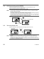
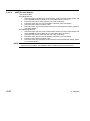
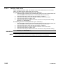
3.2.4
Switching measuring system (ABS/INC)
This can be operated only in the normal mode, not in the peak detection mode.
Press the center key to switch from ABS to INC.
Press and hold the center key to switch from INC to ABS.
・ When the system is switched from ABS to INC, also display value will be set to the zero.
NOTE ・ It cannot switch from ABS to INC while the spindle is moving. So switch from ABS to
INC after stopping the spindle.
・ If switching is required in the peak detection mode, press the lower left key a few times
to change the mode to the normal, and then switch the system.
・ It may not switch from ABS to INC when the calculation coefficient “C” is not being set
to 0 and Overflow error of display value (Err30) is occurring. If it occurs, switch from
ABS to INC after moving the spindle to an appropriate position.
ABS system measurement mode START/ZERO
ABS
INC system measurement mode
START/ZERO
ABS Press and hold
3.2.5
Zero-setting display value
Press the center key in the normal mode, the display value is set to zero.
INC system
measurement mode
START/ZERO
ABS
NOTE
3-8
・ It cannot set to zero while the spindle is moving. So set to zero after stopping the
spindle.
・ It may not set to zero when the calculation coefficient “C” is not being set to 0 and
Overflow error of display value (Err30) is occurring. If it occurs, set to zero after moving
the spindle to an appropriate position.
No. 99MAH034B
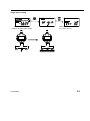
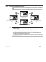
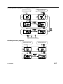
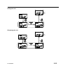
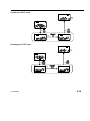
3.2.6
Changing to peak detection mode
Press the lower left key to switch the mode between the normal mode and peak detection
mode.
Pressing the lower left key to check each peak value by changing the display "TIR", "Max",
and "Min" while the run-out, maximum and minimum value are held.
PEAK
PEAK
Normal mode
Minimum value detection mode
3.2.6.3
Run-out detection mode
3.2.6.1
PEAK
PEAK
Maximum value detection mode
3.2.6.2
NOTE
No. 99MAH034B
・ In the peak detection mode, start measuring while the contact point is contacting the
measuring target.
・ Note that the displacement caused by vibration, impact, etc. is detected.
・ Detecting the peak will be being continued until changing to the normal mode.
・ Holding the display value is possible in the peak detection mode. (Refer to "3.2.7
Holding display value".)
・ The run-out, maximum value and minimum value can be confirmed to change the
operation mode during holding the display value.
・ The operation mode cannot be changed from peak detection to the normal mode while
the display value is held.
3-9
3.2.6.1
Run-out detection mode ”TIR”
Hold the run-out of fluctuating measurement data (maximum value - minimum value).
When the tolerance judgment condition has been set, the instrument displays the result of
tolerance judgment for the run-out.
1. Press the lower left key a few times until "TIR" is displayed.
2. Press the center key. Run-out detection measurement is started.
3. When the measurement data exceeds either the maximum or minimum value, the
display value will be updated.
During update, "Max" or "Min" will blink.
4. The detected run-out will be held until the center key is pressed next time. Press the
center key to restart run-out measurement.
・ When either a maximum or minimum value pointer of the analog bar is out of
NOTE
displayable range, the analog bar graduation automatically change by selecting the
“Auto”.
・ The tolerance judgment in the run-out detection mode is made by comparing the actual
run-out value with the tolerance value (upper limit - lower limit).
3.2.6.2
Maximum value detection mode ”Max”
Hold the maximum value of fluctuating measurement data. When the tolerance judgment
condition has been set, the instrument displays the result of tolerance judgment for the
maximum value.
1. Press the lower left key a few times until "Max" is displayed.
2. Press the center key. Maximum value detection measurement is started.
3. When the measurement data exceeds the maximum value, "Max" starts blinking and
the value is updated.
4. The detected maximum value will be held until the center key is pressed next time.
Press the center key to restart maximum value measurement.
・ The maximum point can be edited into a desired value. So this instrument can
NOTE
measure based on this point. Refer to "3.2.2 Preset setting" to set the preset.
・ When a maximum value pointer of the analog bar is out of displayable range, the
pointer automatically moves to the center.
3.2.6.3
Minimum value detection mode ”Min”
Hold the minimum value of fluctuating measurement data. When the tolerance judgment
condition has been set, the instrument displays the result of tolerance judgment for the
minimum value.
1. Press the lower left key a few times until "Min" is displayed.
2. Press the center key. Minimum value detection measurement is started.
3. When the measurement data falls below the minimum value, "Min" starts blinking and
the value is updated.
4. The detected minimum value will be held until the center key is pressed next time.
Press the center key to restart minimum value measurement.
3-10
No. 99MAH034B
NOTE
TIP
・ The minimum point can be edited into a desired value. So this instrument can measure
based on this point. Refer to "3.2.2 Preset setting" to set the preset.
・ When a minimum value pointer of the analog bar is out of displayable range, the
pointer automatically moves to the center.
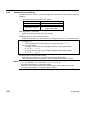
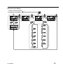
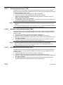
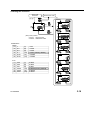
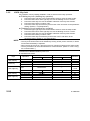
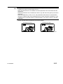
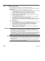
・ The following describes examples of display value and tolerance judgment in each
measurement mode.
Upper limit 8.000
10.000
c
a
5.000
0
0.000
Lower limit
-3.000
b
d
-5.000
Example of display value in each measurement mode
0
→
a
→
b
→
c
→
d
Normal 0.000
5.000
-5.000
10.000
0.000
TIR
0.000
5.000
10.000
15.000
Max
0.000
5.000
10.000
Min
0.000
-5.000
Example of tolerance judgment (upper limit 8.000, Lower limit-3.000)
0
a
b
c
d
Normal
TIR
Max
Min
No. 99MAH034B
3-11
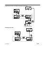
3.2.7
Holding display value (when a data processor is not connected)
Press the lower right key in the measurement mode. "H" is displayed and the display value
will be held. Press the lower right key again to release the hold.
・ If a data processor is connecting to this instrument during “H” is displayed, the held
NOTE
value will be output to it and then be released.
・ The spindle position is being detected while “H” is displayed.
3.2.8
Display value output (when a data processor is connected)
The display value can be output to the data processor.
Press the lower right key in the measurement mode to output the display value to the data
processor.
Refer to "4 Data Output" for cable connections, pin assignment, output format, and timing
chart.
・ To use the data output function properly, refer to the operation manual of the data
NOTE
processor to be connected.
・ When inputting a data output request (REQ) from a data processor, the spindle must
be stopped. Otherwise, this instrument may output wrong data or may not output.
・ If this instrument receives data output request (REQ) signals repeatedly at short
intervals, it may not output a data.
3.2.9
Centering pointer of analog bar
When the pointer of the analog bar is out of displayable range, move the pointer to the
center by setting up the graduation of the bar. It is same as in the case of mechanical dial
indicator, shifting the bezel to a desired scale position.
Press the upper left key in each measurement mode in order to center the pointer of
analog bar.
・Normal mode
: Current measuring position
・Run-out detection mode
: Center of the run-out
: Center of the tolerance value, when enabling the
tolerance judgment function.
・Maximum value detection mode
: Maximum value
・Minimum value detection mode
: Minimum value
・ It cannot center the pointer of analog bar when enabling the tolerance judgment
NOTE
function except Run-out detection mode. Because setting to the center of the tolerance
value at all time.
3.2.10
Switching units (in/mm)
Press and hold the lower right key to switch the display unit between inch and metric.
・ When the unit is switched, the following will be converted accordingly: display value,
NOTE
preset values, tolerance value, resolution, calculation coefficients (B, C), origin offset
value, and analog bar graduation.
If it causes the overflow error of display value (Err 30), set the proper resolution.
Also, it causes overflow error of each setting values or conversion error, it is
recommended to check the values of each setting after switching unit.
・ The display unit can be switched only in the normal mode. So if switching is required in
the peak detection mode, press the lower left key a few times to change the mode to
the normal, and then switch.
3-12
No. 99MAH034B
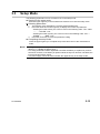
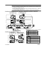
3.3
Setup Mode
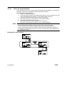
The following parameters can be checked or set in the setup mode.
Starting up the setup mode
Press the upper right key in the measurement mode to move into the setup mode.
Selecting parameters
1.
2.
3.
The blinking cursor indicates the currently selected parameter.
Press the lower left or lower right key to display the current set parameter.
・Pressing the lower left key, the cursor moves in the following order: TOL→RES
→ ... →OTHER→TOL.
・Pressing the lower right key, the cursor moves in the following order: TOL→
OTHER→ ... →RES→TOL.
Press the center key to move the parameter setting
Completing the setup mode
Press the upper right key to complete setup mode and return to the measurement
mode,
NOTE ・ During the setup mode, key assists which correspond to each key will be displayed.
(Refer to "1.4 Details of Display Unit".)
・ The setup parameters will be registered even after the battery is replaced or power is
turned off. However, if the battery is replaced while the key-lock function is enabled, the
key-lock function will be set off.
・ The power supply cannot be turned off with the upper left key in the setup mode.
No. 99MAH034B
3-13
Measurement mode
MENU
OK
3.3.1 TOL
Tolerance judgment
OK
3.3.2 RES
Resolution
OK
EXIT
3.3.3 CALC
Calculation function
OK
Measurement
mode
3.3.4 SCALE
Analog bar graduation
OK
3.3.5 LOCK
Key-lock
OK
3.3.6 OTHER
Other functions
3-14
No. 99MAH034B
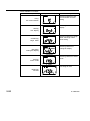
Parameters
Parameter
Example of display
Settings
Selecting ON/OFF of
tolerance judgment and
tolerance value setting
TOL
(Tolerance judgment)
“ON” or ”OFF”
Selecting resolution of the
display
RES
(Resolution)
Current resolution
Selecting ON/OFF of
calculation function and
coefficients setting
CALC
(Calculation function)
“ON” or ”OFF”
Selecting analog bar
graduation
SCALE
(Analog bar graduation)
Current analog bar
graduation
Selecting ON/OFF of key-lock
function
LOCK
(Key-lock)
“ON” or ”OFF”
Setting other functions
(Refer to "3.3.6 OTHER:
Other functions".)
OTHER
(Other functions)
“other”
No. 99MAH034B
3-15
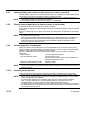
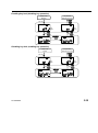
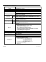
3.3.1
TOL: Tolerance judgment
The tolerance judgment function compares measurement data (display value) with
tolerance values (upper/lower limit) for OK/NG judgment. The tolerance values can be set
in ABS system (P1, P2, P3) and INC system respectively.
Enabling tolerance judgment. Changing tolerance values
1.
2.
3.
4.
5.
6.
7.
8.
Press the upper right key in the measurement mode to move the setup mode.
Press the lower left or lower right key to move the blinking cursor to "TOL".
Press the center key to move the ON/OFF selection of the tolerance judgment
function.
Press the lower left key to select "ON".
Press the center key to move the tolerance value setting (upper/lower limit).
The upper limit sign is blinking, and currently set value will be displayed.
When press the lower left key, the display switches to the lower limit. (Pressing the
lower left key, the upper limit and the lower limit switch.)
The lower limit sign (or the upper limit sign) is blinking, and the currently set lower
limit (or the upper limit) will be displayed.
To edit the tolerance value, select the target value and press the lower right key.
The numerical value editing will be enabled. (Refer to "3.2.3 Numerical value
editing".)
Press the center key after checking or editing the tolerance values. The tolerance
judgment is set "ON", and the mode returns to the parameter setting. (Refer to
"3.3 Setup Mode".)
Disabling tolerance judgment
1.
2.
3.
Press the upper right key in the measurement mode to move the setup mode.
Press the lower left or lower right key to move the blinking cursor to "TOL".
Press the center key to move the ON/OFF selection of the tolerance judgment
function.
4. Press the lower left key to select "OFF".
5. Press the center key to set the tolerance judgment "OFF" and return to the
parameter setting. (Refer to "3.3 Setup Mode".)
・ The tolerance values will be set in the currently active system (ABS (P1, P2, P3) or
IMPORTANT
INC). Check the desired measuring system is selected before setting the tolerance
judgment function.
・ The tolerance values will be calculated automatically according to the unit or the
resolution. Check the tolerance values after the resolution is changed since the
conversion error may occur.
NOTE ・ Press the upper left key to cancel the operation.
・ The tolerance judgment in the run-out detection mode is made by comparing the actual
run-out value with the tolerance value (upper limit - lower limit).
・ If the upper limit is set lower than the lower limit, the tolerance upper/lower limit setting
error (Err 90) will occur. Reset the values to be the upper limit is greater than the lower
limit.
・ The tolerance judgment setting cannot be completed if Overflow error of upper / lower
limit value (Err95) is occurring. Reset the upper or lower limit value.
3-16
No. 99MAH034B
Enabling tolerance judgment. Changing tolerance values
Tolerance judgment ON
Measurement mode
Measurement mode
EXIT
(1), (2)
TOL
RES
CALC
TOL
RES
CALC
OK
(3)
SELECT
(4)
OK
(5)
OK
SELECT
(6)
EDIT
(8)
(7)
Numerical value editing
Disabling tolerance judgment
Tolerance judgment ON
Measurement mode
Tolerance judgment OFF
Measurement mode
EXIT
(1), (2)
TOL
RES
CALC
TOL
RES
CALC
(3) OK
OK
SELECT
(5)
(4)
No. 99MAH034B
3-17
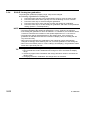
3.3.2
RES: Resolution
The resolution of the display can be changed.
Selecting the resolution
1.
2.
3.
4.
5.
Press the upper right key in the measurement mode to move the setup mode.
Press the lower left or lower right key to move the blinking cursor to "RES".
Press the center key to set the resolution.
Press the lower left or lower right key to switch the resolution.
Press the center key to set the resolution and the mode returns to the parameter
setting. (Refer to "3.3 Setup Mode".)
・
The
preset
values (P1, P2, P3) and the tolerance values (upper and lower limits) will be
IMPORTANT
calculated automatically according to the resolution. Check the values after changing
the resolution, since the conversion error or overflow error (Err95) may occur.
NOTE ・ Press the upper left key to cancel the operation.
・ The coefficients (A, B, C) and the origin offset value will not be changed by changing
the resolution.
・ Set up a greater resolution than 0.001mm in disabling the calculation function. If
0.0005mm or 0.0002mm is set in this condition, a last digit will not be changed.
Because the resolution of the spindle displacement "x" is "0.001mm".
・ When the unit is switched, the resolution will be automatically changed accordingly.
Check the resolution after switching the unit.
・ When the unit is hidden (refer to "3.3.6.2 UNIT(2): Unit display"), the resolution will be
same as the previously set unit.
3-18
No. 99MAH034B
Selecting the resolution
Setup mode
Resolution
Measurement mode
(4)
EXIT
(1), (2)
OK
(Note)
(3)
TOL
RES
CALC
OK
(5
(Note) Factory default
0.001mm : ISO/JIS models
0.00005in : ASME/AGD models
Resolutions
Metric
(1)
(2)
(3)
(4)
(5)
(6)
1
0.5
0.2
0.1
0.05
0.02
(7)
(8)
(9)
(10)
(11)
(12)
0.01
0.005
0.002
0.001 (Factory default)
0.0005
0.0002
0.05
0.02
0.01
0.005
0.002
0.001
(7)
(8)
(9)
(10)
(11)
(12)
0.0005
0.0002
0.0001
0.00005 (Factory default)
0.00002
0.00001
Inch
(1)
(2)
(3)
(4)
(5)
(6)
No. 99MAH034B
3-19
3.3.3
CALC: Calculation function
This special instrument supports measurements by internal calculations using the formula
-1
f(x)=Ax+B+Cx (“x” is a spindle displacement). The calculation coefficients (A, B, C) can
be set.
Enabling the calculation function. Checking or changing the calculation coefficients.
1. Press the upper right key in the measurement mode to move the setup mode.
2. Press the lower left or lower right key to move the blinking cursor to "CALC".
3. Press the center key to move the ON/OFF selection of the calculation function.
4. Press the lower left key to select "ON".
5. Press the center key to move the calculation coefficient setting (A, B, C).
The coefficient signs (A, B, C) will blink, and currently set value will be displayed.
6. Press the lower left key to change the calculation coefficient.
7. To change the calculation coefficient, select the target coefficient and press the
lower right key. The numerical value editing will be enabled. (Refer to "3.2.3
Numerical value editing".)
8. Press the center key after checking or changing the calculation coefficients. The
calculation function is set "ON", and the mode returns to the parameter setting.
(Refer to "3.3 Setup Mode".)
9. Set up the origin point. (Refer to “3.2.1 Origin point setting”.)
Disabling the calculation function
1.
2.
3.
4.
5.
Press the upper right key in the measurement mode to move the setup mode.
Press the lower left or lower right key to move the blinking cursor to "CALC".
Press the center key to move the ON/OFF selection of the calculation function.
Press the lower left key to select "OFF".
Press the center key to set the calculation function "OFF" and return to the
parameter setting. (Refer to "3.3 Setup Mode".)
・
When
enabling the calculation function or changing the calculation coefficient in the
IMPORTANT
ABS system, the preset position will be cleared (Preset No. will be disappeared.).
However the preset value can be called, as it is being registered.
・ When enabling the calculation function or changing the calculation coefficient in the
INC system, the zero set position will be cleared (“INC” will be disappeared.). Set to
zero after moving the spindle to an appropriate position. (Refer to "3.2.5 Zero-setting
display value".)
NOTE ・ Press the upper left key to cancel the operation.
・ Overflow error of display value (Err30) may occur as a result of calculation. (Refer to "5
ERROR MESSAGES AND ACTION".)
・ Set up the calculation coefficients and the resolution to be a proper combination. If this
combination is not proper, a last digit will not be changed. Because the resolution of the
spindle displacement "x" is "0.001mm".
Example) Resolution=0.0002mm, Calculation coefficients: A=1, B=C=0
・ The factory default of the calculation coefficients are A=1, B=C=0.
・ The calculation function setting cannot be completed if the calculation coefficient A is
set to zero. Reset the calculation coefficient A.
・ The calculation coefficients (A, B, C) will not be converted by the resolution changing.
3-20
No. 99MAH034B
・ The calculation coefficients (B, C) will be calculated automatically according to the unit.
Check the calculation coefficients after the unit is changed since the conversion error
or overflow error (Err95) may occur.
・ Set up the origin offset to add an offset value to the spindle displacement "x". (Refer to
"3.3.6.3 OFFSET(3): Origin offset".)
・ The number of digits available for each calculation coefficient is described below.
Enabling the calculation function. Checking or changing the calculation coefficients.
Calculation function ON
Measurement mode
Setup mode
Calculation function
EXIT
(1), (2)
-1
-1
Ax+B+Cx
Ax+B+Cx
TOL
RES
CALC
TOL
RES
CALC
(3)
OK
SELECT
(4)
-1
Ax+B+Cx
(5)
SELECT
(6)
-1
Ax+B+Cx
OK
SELECT
(6)
-1
Ax+B+Cx
SELECT
OK
(6)
-1
Ax+B+Cx
(8)
EDIT
(7)
Numerical value editing
Disabiling the calculation function
Setup mode
Calculation function
(1), (2)
Calculation function OFF
Measurement mode
EXIT
-1
Inch models
mm
A
inch
-1
Ax+B+Cx
Ax+B+Cx
TOL
RES
CALC
TOL
RES
CALC
OK
OK
(5)
(3)
Configurable number of digits for calculation coefficient
Metric model
2 digits before the decimal point,
A
4 digits after the decimal point
2 digits before the decimal point,
B
4 digits after the decimal point
5 digits before the decimal point,
C
1 digits after the decimal point
mm
B
inch
SELECT
-1
Ax+B+Cx
(4)
mm
C
inch
No. 99MAH034B
2 digits before the decimal point,
4 digits after the decimal point
2 digits before the decimal point,
4 digits after the decimal point
1 digits before the decimal point,
5 digits after the decimal point
5 digits before the decimal point,
1 digits after the decimal point
2 digits before the decimal point,
4 digits after the decimal point
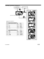
3-21
3.3.4
SCALE: Analog bar graduation
The analog bar graduation (Display range: ±20) can be changed.
Selecting a graduation of analog bar
1.
2.
3.
4.
5.
Press the upper right key in the measurement mode to move the setup mode.
Press the lower left or lower right key to move the blinking cursor to "SCALE".
Press the center key to set the analog bar graduation.
Press the lower left or lower right key to switch the analog bar graduation.
Press the center key to set the analog bar graduation and return to the parameter
setting. (Refer to "3.3 Setup Mode".)
・
Press
the upper left key to cancel the operation.
NOTE
・ The factory default of the analog bar graduation is "Auto". Change it as required.
・ If the analog bar graduation is set to "0.0005mm" or "0.0002mm", the resolution will be
"0.001mm". Because the resolution of the spindle displacement "x" is "0.001mm".
・ The analog bar will be displayed based on the display value. If the analog bar
graduation is selected lower than the resolution of display value, the analog bar will
vary discontinuously.
・ When the unit is switched, the graduation of the analog bar will be automatically
changed accordingly. After switching the unit, check the graduation of the analog bar.
・ When the unit is hidden (refer to "3.3.6.2 UNIT(2): Unit display"), the graduation will be
same as the previously set unit.
TIP
3-22
・ The graduation of the analog bar will change automatically in the following conditions:
1. Run-out detection mode: Graduation will change run-out to be within the display
range.
2. Tolerance judgment ON: Graduation will change tolerance values to be within the
display range.
3. Changing resolution: Graduation will change same as resolution.
No. 99MAH034B
Selectiong a graduation of analog bar
Setup mode
Analog bar graduation
Measurement mode
EXIT
(1), (2)
(4)
OK
(Note)
(3)
SCALE
LOCK
OTHER
(Note) Factory default: Auto
OK
(5)
Analog bar graduations
Metric
(1)
(2)
(3)
(4)
(5)
(6)
(7)
Auto (Factory default)
5
1
0.5
0.2
0.1
0.05
(8)
(9)
(10)
(11)
(12)
(13)
(14)
0.02
0.01
0.005
0.002
0.001
0.0005
0.0002
Inch
(1)
(2)
(3)
(4)
(5)
(6)
(7)
Auto (Factory default)
0.2
0.05
0.02
0.01
0.005
0.002
(8)
(9)
(10)
(11)
(12)
(13)
(14)
0.001
0.0005
0.0002
0.0001
0.00005
0.00002
0.00001
No. 99MAH034B
3-23
3.3.5
LOCK: Key-lock
Key operation can be partially disabled in order to avoid incorrect key operation.
Enabling key-lock (disabling key operation)
1.
2.
3.
4.
5.
Press the upper right key in the measurement mode to move the setup mode.
Press the lower left or lower right key to move the blinking cursor to "LOCK".
Press the center key to move the ON/OFF selection of the key-lock function.
Press the lower left key to select "ON".
Press the center key to set the key-lock function "ON" and return to the parameter
setting. (Refer to "3.3 Setup Mode".)
Disabling key-lock (enabling key operation)
1.
2.
3.
4.
5.
Press the upper right key in the measurement mode to move the setup mode.
Press the lower left or lower right key to move the blinking cursor to "LOCK".
Press the center key to move the ON/OFF selection of the key-lock function.
Press the lower left key to select "OFF".
Press the center key to set the key-lock function "OFF" and return to the
parameter setting. (Refer to "3.3 Setup Mode".)
・
Press
the upper left key to cancel the operation.
NOTE
・ The key-lock function will not be disabled by turning off the power. However, it will be
set off when the battery is replaced.
・ When the key-lock is set on, other than key-lock cannot be selected in the setup mode.
・ The key-lock items can be customized via PC communication. (Refer to "3.3.6.1 PC(1):
PC communication".)
Keys
Lower left key
Center key
Lower right key
Upper left key
Upper right key
3-24
Functions to be disabled while key-lock is on
Measurement mode
Key names
Disabled functions
Operation
Metric model Inch models Metric model Inch models
Press
PEAK
○
Press and Hold
PRESET
○
Press
ZERO
○
Press and Hold
ABS
○
Press
Press and Hold
Press
Press and Hold
Press
Press and Hold
―
DATA/HOLD
―
in/mm
ON/OFF
MENU
ORIGIN
―
○
○
―
―
○
Remarks
3.2.6
3.2.2
3.2.5
3.2.4
3.2.7
3.2.8
3.2.10
3.2.9
3.1
3.3
3.2.1
No. 99MAH034B
Enabling key-lock (disabling key operation)
Setup mode
Keylock
Key-lock ON
Measurement mode
EXIT
(1), (2)
SCALE
LOCK
OTHER
SCALE
LOCK
OTHER
OK
OK
(3)
(5)
SELECT
(4)
Disabling key-lock (enabling key operation)
Setup mode
Keylock
Key-lock OFF
Measurement mode
EXIT
(1), (2)
SCALE
LOCK
OTHER
(3)
SCALE
LOCK
OTHER
OK
OK
(5)
SELECT
(4)
No. 99MAH034B
3-25
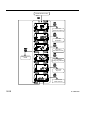
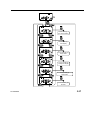
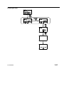
3.3.6
OTHER: Other functions
Check or set up the PC communication or the unit display.
Selecting items available in OTHER functions
1.
2.
3.
4.
Press the upper right key in the measurement mode to move the setup mode.
Press the lower left or lower right key to move the blinking cursor to "OTHER".
Press the center key to move the ON/OFF selection of OTHER functions.
Press the lower left or lower right key to change the item in the other functions.
•Pressing the lower left key, the display changes in the following order:
PC communication → Unit display →...→ All reset → PC communication
•Pressing the lower right key, the display changes in the following order:
PC communication → All reset→...→ Unit display → PC communication.
5. Press the center key to return to the parameter setting.
NOTE ・ Press the upper left key to cancel the operation.
3-26
No. 99MAH034B
SCALE
LOCK
OTHER
OK
OK
3.3.6.1 PC (1)
PC communication
OK
3.3.6.2 UNIT (2)
Unit display
OK
3.3.6.3 OFFSET (3)
Origin offset
OK
3.3.6.4 RULER (4)
Analog bar display
OK
3.3.6.5 FAST (5)
FAST mode
OK
3.3.6.6 RESET (6)
All reset
No. 99MAH034B
3-27
Items available in OTHERs
Other functions (Item No.)
Example of LCD display
Settings
Selecting ON/OFF of PC
communication for each
setting
PC(1)
PC communication
1, PC
Selecting ON/OFF of unit
display
UNIT(2)
Unit display
2, UNIT
Selecting ON/OFF of origin
offset, and origin offset
value setting
OFFSET(3)
Origin offset
3, OFFSET
Selecting ON/OFF of
analog bar display
RULER(4)
Analog bar display
4, RULER
Selecting ON/OFF of FAST
mode
FAST(5)
FAST mode
5, FAST
Executing all reset
RESET(6)
All reset
6, RESET
3-28
No. 99MAH034B
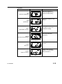
3.3.6.1
PC(1): PC communication
This instrument can set up or change various items with special software, if it connects to
Personal computer with a Parameter setup kit (optional accessory).
Enabling PC communication
1.
2.
Connect a Parameter setup kit.
Press the upper right key in the measurement mode to move the setup mode, and
select OTHER functions. (Refer to "3.3.6 OTHER: Other functions".)
3. Press the lower left or lower right key until "PC" is blinking.
4. Press the center key to move the PC communication setting.
5. Press the lower left key to select "ON".
6. Press the center key to start communication with the PC.
When the communication is started, "PC con" will be displayed.
NOTE ・ Press the upper left key to cancel the communication with the PC.
・ Remove the cap of the output connector, and securely connect the cable.
・ Do not disconnect the Parameter setup kit while communicating with the PC.
・ When communication with PC is finished, the measurement mode will be restored.
・ For details of communication with the PC, refer to the operation manual supplied with
the Parameter setup kit.
Enabling PC communication
(4)
OK
SELECT
(5)
(6)
No. 99MAH034B
OK
3-29
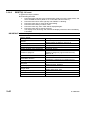
Configurable items by external input
Configurable items
Settings
Preset No.: P1 / P2 / P3
Preset
Preset value: P1 / P2 / P3
Measuring system
ABS system / INC system
Unit
mm / in (only inch models)
OFF/ Run-out detection mode/ Maximum value detection mode/ Minimum
Peak detection mode
value detection mode
ON / OFF
Tolerance judgment
Upper and lower limit of each measuring system
(ABS (P1, P2, P3) and INC)
Metric 0.0002 / 0.0005 / 0.001 / 0.002 / 0.005 / 0.01 / 0.02 / 0.05 / 0.1 / 0.2 / 0.5 / 1
Resolution
0.00001 / 0.00002 / 0.00005 / 0.0001 / 0.0002 / 0.0005 / 0.001 / 0.002 /
Inch
0.005 / 0.01 / 0.02 /0.05
ON / OFF
Calculation function
Calculation coefficients: A/ B/ C
AUTO / 0.0002 / 0.0005 / 0.001 / 0.002 / 0.005 / 0.01 / 0.02 / 0.05 / 0.1 / 0.2 /
Metric
0.5 / 1 / 5
Analog bar graduation
AUTO / 0.00001 / 0.00002 / 0.00005 / 0.0001 / 0.0002 / 0.0005 / 0.001 /
Inch
0.002 / 0.005 / 0.01 / 0.02 / 0.05 / 0.2
ON / OFF
Key-lock setting (multiple selection possible)
・PEAK (Changing the peak detection mode)
・PRESET(Preset setting)
・ZERO (Zero-set of display value)
Key-lock
・ABS (Switching the measuring system)
・DATA/HOLD (Holding the display value/Display value output)
・in/mm (Switching the unit (inch⇔mm))
・→|← (Centering the analog bar)
・ORIGIN (Origin point setting)
Unit display
ON / OFF
ON / OFF
Origin offset
Origin offset value
Analog bar display
ON / OFF
FAST mode
ON / OFF
ON / OFF
Parameter-lock setting (multiple selection possible)
・Preset value setting: P1/ P2/ P3
・Tolerance setting: P1: upper limit/lower limit,
P2: upper limit/lower limit
Parameter-lock
P3: upper limit/ lower limit,
INC: upper limit, lower limit
・Calculation coefficient setting: A/ B/ C
・Origin offset value setting
・MENU key
3-30
No. 99MAH034B
TIP
・ The parameter-lock function is to disable each setting and all reset operation, and it is
available only while communicating with PC.
・ When the parameter lock is enabled, the locked parameter cannot be edited with the
instrument.
・ While the parameter lock is enabled, the "EDIT" sign with the lower right key will not be
displayed.
・ When the MENU Key is set to “Lock”, the parameters other than PC communication
cannot be confirmed and set by operating the key of this instrument. Release the Lock
of MENU Key by conducting the PC communication if you want to confirm or set each
parameter.
Display example during parameter-lock (Preset setting)
【Parameter-lock OFF】
【Parameter-lock ON】
※The "EDIT" sign will not be displayed
No. 99MAH034B
3-31
3.3.6.2
UNIT(2): Unit display
Unit can be hidden.
Hiding the unit
1.
2.
3.
4.
5.
Press the upper right key in the measurement mode to move the setup mode, and
select OTHER functions. (Refer to "3.3.6 OTHER: Other functions".)
Press the lower left or lower right key until "Unit" is blinking.
Press the center key to move the ON/OFF selection of the unit display.
Press the lower left key to select "OFF".
Press the center key to hide the unit and return to the parameter setting. (Refer to
"3.3 Setup Mode".)
Displaying the unit
1.
Press the upper right key in the measurement mode to move the setup mode, and
select OTHER functions. (Refer to "3.3.6 OTHER: Other functions".)
2. Press the lower left or lower right key until "Unit" is blinking.
3. Press the center key to move the ON/OFF selection of the unit display.
4. Press the lower left key to select "ON".
5. Press the center key to display the unit and return to the parameter setting. (Refer
to "3.3 Setup Mode".)
・
When
the unit is hidden, "." (dot) will be displayed.
NOTE
・ When the unit is hidden, the graduation will be same as the previously set unit.
3-32
No. 99MAH034B
Hiding the unit
SCALE
LOCK
OTHER
(3)
OK
OK
(5)
SELECT
(4)
Displaying the unit
SCALE
LOCK
OTHER
OK
OK
(3)
(5)
SELECT
(4)
No. 99MAH034B
3-33
3.3.6.3
OFFSET(3): Origin offset
Origin offset adds an offset value “d” to the spindle displacement "x".
And then enables measuring with the formula, f(x)=A(x+d)+B+C(x+d) , when Calculation
function is ON.
Enabling origin offset. Checking and changing origin offset
1.
2.
3.
4.
5.
6.
7.
Press the upper right key in the measurement mode to move the setup mode, and
select OTHER functions. (Refer to "3.3.6 OTHER: Other functions".)
Press the lower left or lower right key until "OFFSET" is blinking.
Press the center key to move the ON/OFF selection of the origin offset.
Press the lower left key to select "ON".
Press the center key to move the setting of the origin offset value. The currently
set origin offset will be displayed.
To change the origin offset, press the lower right key and move the numerical
value setting. (Refer to "3.2.3 Numerical value setting".)
Press the center key after checking or changing the origin offset value. The origin
offset is set "ON", and the mode returns to the parameter setting. (Refer to "3.3
Setup Mode".)
Disabling origin offset
1.
2.
3.
4.
5.
Press the upper right key in the measurement mode to move the setup mode, and
select OTHER functions. (Refer to "3.3.6 OTHER: Other functions".)
Press the lower left or lower right key until "OFFSET" is displayed blinking.
Press the center key to move the ON/OFF selection of the origin offset.
Press the lower left key to select "OFF".
Press the center key to set the origin offset "OFF" and return to the parameter
setting. (Refer to "3.3 Setup Mode".)
IMPORTANT ・ When enabling the origin offset or changing the origin offset value while the calculation
function (Refer to "3.3.3 Calculation function".) is enabled in the ABS system, the
preset position will be cleared( Preset No. will be disappeared.). However the preset
value can be called, as it is being registered.
・ When enabling the origin offset or changing the origin offset value while the calculation
function (Refer to "3.3.3 Calculation function".) is enabled in the INC system, the zero
set position will be cleared (“INC” will be disappeared.). Set to zero after moving the
spindle to an appropriate position. (Refer to "3.2.5 Zero-setting display value".)
NOTE ・ Switching the resolution will not convert the origin offset value.
・ The origin offset value will be calculated automatically according to the unit. Check the
origin offset value after the unit is changed, since the conversion error or overflow error
(Err95) may occur.
・ The origin offset setting cannot be completed if Overflow error of origin offset value
(Err95) is occurring. Reset the origin offset value.
3-34
No. 99MAH034B
Enabling origin offset. Checking and changing origin offset
SCALE
LOCK
OTHER
OK
(3)
SELECT
(4)
(5)
OK
OK
(7)
EDIT
(6)
Numerical value editing
Disabling origin offset
SCALE
LOCK
OTHER
(3)
OK
OK
(5)
SELECT
(4)
No. 99MAH034B
3-35
3.3.6.4
RULER(4): Analog bar display
Analog bar can be set up displayed or hidden.
Hiding the analog bar
1.
2.
3.
4.
5.
Press the upper right key in the measurement mode to move the setup mode, and
select OTHER functions. (Refer to "3.3.6 OTHER: Other functions".)
Press the lower left or lower right key until "RULER" is blinking.
Press the center key to move the ON/OFF selection of the analog bar display.
Press the lower left key to select "OFF".
Press the center key to hide the analog bar and return to the parameter setting.
(Refer to "3.3 Setup Mode".)
Displaying the analog bar
1.
Press the upper right key in the measurement mode to move the setup mode, and
select OTHER functions. (Refer to "3.3.6 OTHER: Other functions".)
2. Press the lower left or lower right key until "RULER" is blinking.
3. Press the center key to move the ON/OFF selection of the analog bar display.
4. Press the lower left key to select "ON".
5. Press the center key to hide the analog bar and return to the parameter setting.
(Refer to "3.3 Setup Mode".)
・
The
analog
bar will not be displayed if the graduation is changed while it is hidden.
NOTE
(Refer to "3.3.4 SCALE: Selecting analog bar graduation".)
3-36
No. 99MAH034B
Hiding the analog bar
SCALE
LOCK
OTHER
OK
OK
(5)
(3)
SELECT
(4)
Displaying the analog bar
SCALE
LOCK
OTHER
OK
OK
(5)
(3)
SELECT
(4)
No. 99MAH034B
3-37
3.3.6.5
FAST(5): FAST mode
When enabling the FAST mode, the detection cycle in the peak detection mode will be
20ms. It enables to detect peak value more correctly.
Enabling the FAST mode (Detection cycle: 20msec)
1.
2.
3.
4.
5.
Press the upper right key in the measurement mode to move the setup mode, and
select OTHER functions. (Refer to "3.3.6 OTHER: Other functions".)
Press the lower left or lower right key until "FAST" is blinking.
Press the center key to move the ON/OFF selection of the FAST mode.
Press the lower left key to select "ON".
Press the center key to enable this function and return to the parameter setting.
(Refer to "3.3 Setup Mode".)
Disabling the FAST mode(Detection cycle: 100msec)
1.
Press the upper right key in the measurement mode to move the setup mode, and
select OTHER functions. (Refer to "3.3.6 OTHER: Other functions".)
2. Press the lower left or lower right key until "FAST" is blinking.
3. Press the center key to move the ON/OFF selection of the FAST mode.
4. Press the lower left key to select "ON".
5. Press the center key to disable this function and return to the parameter setting.
(Refer to "3.3 Setup Mode".)
・
The
accuracy
will not be affected by this function.
IMPORTANT
NOTE ・ Operating in this function will shorten the battery life.
It is recommended to operate with disabling this function if not necessary.
3-38
No. 99MAH034B
Enabling the FAST mode
SCALE
LOCK
OTHER
OK
OK
(5)
(3)
SELECT
(4)
Disabling the FAST mode
SCALE
LOCK
OTHER
OK
OK
(5)
(3)
SELECT
(4)
No. 99MAH034B
3-39
3.3.6.6
RESET(6): All reset
It restores the factory default.
Executing all reset
1.
Press the upper right key in the measurement mode to move the setup mode, and
select OTHER functions. (Refer to "3.3.6 OTHER: Other functions".)
2. Press the lower left or lower right key until "RESET" is blinking.
3. Press the center key to move the all reset setting.
4. Press the lower left key to select "YES".
5. Press the center key, then "YES" will be displayed again.
6. Press the center key to execute all reset.
The display turns off shortly, and restores the display of the time when the battery
is installed.
IMPORTANT ・ The setting before executing all reset cannot be restored.
Factory default
Setting items
Preset
Measuring system
Unit
Peak detection mode
Center position of the analog bar
Tolerance judgment
Resolution
Calculation function
Analog bar graduation
Key-lock
Unit display
Origin offset
Analog bar display
FAST mode
Parameter-lock
3-40
Settings
Preset No. (P1/P2/P3): P1
Preset values (P1/P2/P3): Zero for all
ABS
mm (for inch models: in)
OFF
Centered at zero
OFF
Tolerance judgment (upper limit/lower limit):
Zero for all
0.001mm (0.00005in)
OFF
Calculation coefficients: A=1.0000, B=C=0
Auto
OFF
All key function: Enabled
ON
OFF
Origin offset value: Zero
ON
OFF
OFF
No. 99MAH034B
Excuting all reset
OK
(3)
SELECT
(4)
(5)
OK
OK
(6)
No. 99MAH034B
3-41
3.4
Calibration mode
In this mode the instrument can measure with an appropriate setting of accuracy
inspection and calibration while retaining the current settings in memory. And also in this
mode when the instrument receives an output request (REQ) from the data processor, it
outputs a display value. (Refer to 3.2.8. Display value output)
The settings of calibration mode
(The settings change automatically when starting the calibration mode)
Setting items
Settings
Measurement mode
Normal mode
Measuring system
INC
Unit
mm / in(for inch models)
Resolution
0.001mm / 0.00005in(for inch models)
Other
Tolerance judgment :OFF
Calculation function :OFF
Key-lock :OFF
Analog bar display :OFF
Key function for the calibration mode
Keys
Press
Press and hold
Lower left
Center
Set to zero
Lower right
Changing unit
Upper left
Upper right
-
●Starting the calibration mode
1.
2.
Remove the battery holder by using a flat-blade screwdriver or the like.
While pressing the lower left key and center key, set to the battery holder. This
instrument will be started up in the calibration mode.
●Stopping the calibration mode
1. Remove the battery holder, so it means stopping the calibration mode. The
measurement mode (the normal mode) will be restarted when the battery holder is
set into the original position again (Refer to 2. SETUP).
・
The
preset setting is required in the measurement mode after using this mode (Refer
IMPORTANT
to 3.2.2. Preset setting). And also set the origin point if you want because the origin
point setting is cleared (Refer to 3.2.1. Origin point setting). However other settings
and parameters are held with the former setting which moves to this mode.
PEAK START/ZERO
(2)
+
Set the battery holder
(1)
3-42
Calibration mode
No. 99MAH034B
4
4
DATA OUTPUT
This chapter describes how to output data.
The measurement data can be outputted to the data processor such as Digimatic
Mini-processor DP-1VR with an optional connecting cable (Parts No. 905338 (1m) or No.
905409 (2m)). And the data can be summed up or recorded
・ Use only the output cable of Mitutoyo specific accessories. The use of an improper
NOTE
cable or deteriorated cable may disable data output.
・ Prior to data output carefully read the user’s manual of the data processor to use it
correctly.
4.1
Cable Connection
Remove the output connector cap, and then connect the instrument to the data processor
by using a connecting cable. Insert the cable securely to the end, in the direction as
shown.
Cap
Connecting cable
・ Store the removed cap, taking care to prevent loss.
NOTE ・ Install the direction of output pin correctly.
・ Be sure to attach a cap to the connecting cable when not in use.
No. 99MAH034B
4-1
4.2
Output Connector
Pin No.
Indicator Cable
1
1
(5)
(1)
Digimatic Indicator
1
9
2
10
Cable
Signal
I/O
GND
-
2*
2
DATA
O
3*
3
CK
O
4*
4
RD
O
5*
5
REQ
I
-
6-10
N.C.
-
CK, RD, DATA
*1
IOL = 500μA
(VOL = 6.05V)
3V
*2
20kΩ
REQ
470pF
CMOS IC
IMPORTANT
4.3
・ Since the power voltage differs between this instrument and the data processor,
absolutely design an output system either open-collector or open-drain. Do not use
CMOS output.
Output Data Format
Decimal point
X. X. X. X. X. X
d1
d2
d3
All "F"(1111)
d4
d5
d6
d7
MSD
Sign
+ :0(0000)
- :8(0001)
d8
d9
d10 d11 d12 d13
LSD
Measurements
Unit
mm :0(0000)
inch :1(1000)
Non :8(0001)
0(0000)
1(1000)
2(0100)
3(1100)
4(0010)
5(1010)
※This instrument outputs 13 digits from d1 to d13 by making 4 bits into 1 digit.
※Each digit is outputted in the order from least significant bit (LSB) to most significant bit (MSB).
4-2
No. 99MAH034B
4.4
Timing Chart
RD
RD
0.7 ms < T1 < 1.2 ms
100 µs < T2 < 200 µs
200 µs < T3 < 300 µs
100 µs < T4 < 200 µs
T5:Determined by the performance
of the data processor
REQ
REQ
DATA
DATA
CK
CK
T5
T1
T2
T3
T4
IMPORTANT
・ If the output request (REQ) signal is received during the spindle displacement or if the
inverter receives output request (REQ) signals repeatedly at short intervals, the
instrument may not output data.
NOTE
・ Retain the REQ signal at Low level until the CK signal is outputted. Also, return the
REQ signal to High level before the last CK signal (at the 52nd bit) is outputted.
No. 99MAH034B
4-3
MEMO
4-4
No. 99MAH034B
5
5
ERROR MESSAGE AND
ACTION
This chapter describes the error messages and their corrective
actions.
If any error occurs in this Digimatic indicator, a corresponding error message is displayed.
If the instrument does not recover the normal conditions after corrective actions, contact
your dealer or Mitutoyo sales office.
Display
definition
Low battery alarm
・ Battery voltage is getting
low
Low battery error
・ Measurement cannot be
performed due to
consumption of the
battery.
Sensor signal synthesizing
error
・ Synthesizing of sensor
signal is failed.
No. 99MAH034B
Actions
・ Replace the battery with the
new one.
・ Replace the battery with the
new one.
・ A sensor signal
synthesizing error occurred
while the spindle was
moving at high speed. Keep
on using the indicator since
this error does not affect
measured values.
* If this error occurs while the
spindle is stopped, it could
be due to sensor failure. In
this case, contact the
nearest Mitutoyo sales
office.
5-1
Overflow error of display
value
・ The display value has
exceeded the maximum
number of digits that can
be displayed.
Setting value rewrite error
・ A setting value has been
rewritten from any cause
after the previous use.
Setting value storage error
・ A setting value could not
be stored.
・ A setting value could not
be loaded.
Internal program error
・ Measurement cannot be
performed due to
occurrence of an
anomaly in the internal
program.
5-2
・ Return the display value to
the permissible number of
digits to automatically reset
the error.
・ Press the center key, or
press and hold
・ Move the Setup mode to
change the resolution.
(Refer to "3.3.2 RES:
Resolution".)
・ Move the Setup mode to
reset the calculation
coefficient.
・ Press the center key will
return to the initial state
after setting the battery.
Perform re-setting after
confirming the setting
value, referring to "2.1
Installation (replacement) of
Battery and Initial Setting".
・ Remove the battery once
and perform re-setting,
referring to "2.1 Installation
(replacement) of Battery
and Initial Setting".
・ If this error occurs even
after re-setting the battery,
replace it.
・ If this error occurs even
after replacing the battery, it
could be due to instrument
failure. In this case, contact
your dealer or Mitutoyo
sales office.
・ This could be due to
instrument failure. In this
case, contact your dealer or
Mitutoyo sales office.
No. 99MAH034B
No. 99MAH034B
Tolerance upper/lower limit
setting error
・ The tolerance limit value
is set with the upper limit
value being smaller than
the lower limit value.
・ Press the center key to
reset to be the upper limit
value is greater than the
lower limit value. (Refer to
"3.3.1 TOL: Tolerance
judgment".)
Overflow error of preset
value
・ The preset value has
exceeded the maximum
number of digits that can
be displayed.
Overflow error of upper limit
value
・ The upper limit value has
exceeded the maximum
number of digits that can
be displayed.
Overflow error of lower limit
value
・ The lower limit value has
exceeded the maximum
number of digits that can
be displayed.
Overflow error of calculation
coefficient
・ The calculation coefficient
has exceeded the
maximum number of
digits that can be
displayed.
Overflow error of origin
offset value
・ The origin offset value has
exceeded the maximum
number of digits that can
be displayed.
・ Press the lower right key to
reset the preset value.
・ Lower the resolution. (Refer
to "3.3.2 RES: Resolution".)
・ Press the lower right key to
reset the upper limit value.
(Refer to "3.3.1 TOL:
Tolerance judgment".)
・ Lower the resolution. (Refer
to "3.3.2 RES: Resolution".)
・ Press the lower right key to
reset the lower limit value.
(Refer to "3.3.1 TOL:
Tolerance judgment".)
・ Lower the resolution. (Refer
to "3.3.2 RES: Resolution".)
・ Press the lower right key to
reset the calculation
coefficients. (Refer to "3.3.3
CAL: Calculation function".)
・ Press the lower right key to
reset the origin offset value
coefficients. (Refer to
"3.3.6.3 OFFSET(3): Origin
offset".)
5-3
MEMO
5-4
No. 99MAH034B
SERVICE NETWORK
Europe
Mitutoyo Europe GmbH
Borsigstrasse 8-10, 41469 Neuss, GERMANY
TEL:49(2137)102-0 FAX:49(2137)102-351
Mitutoyo CTL Germany GmbH
Neckarstrasse 1/8, 78727 Oberndorf, GERMANY
TEL:49(7423) 8776-0 FAX:49(7423)8776-99
KOMEG Industrielle Messtechnik GmbH
Zum Wasserwerk 3, 66333 Völklingen, GERMANY
TEL: 49(6898)91110 FAX: 49(6898)9111100
Germany
Mitutoyo Deutschland GmbH
Borsigstrasse 8-10, 41469 Neuss, GERMANY
TEL:49(2137)102-0 FAX:49(2137)86 85
M3 Solution Center Hamburg
Tempowerkring 9·im HIT-Technologiepark 21079 Hamburg,
GERMANY
TEL:49(40)791894-0 FAX:49(40)791894-50
M3 Solution Center Berlin
Paradiesstrasse 208, 12526 Berlin, GERMANY
TEL:49(30)2611 267 FAX:49(30)26 29 209
M3 Solution Center Eisenach
im tbz Eisenach, Heinrich-Ehrhardt-Platz, 99817 Eisenach,
GERMANY
TEL:49(3691)88909-0 FAX:49(3691)88909-9
M3 Solution Center Ingolstadt
Marie-Curie-Strasse 1a, 85055 Ingolstadt, GERMANY
TEL:49(841)954920 FAX:49(841)9549250
M3 Solution Center Leonberg GmbH
Steinbeisstrasse 2, 71229 Leonberg, GERMANY
TEL:49(7152)6080-0 FAX:49(7152)608060
Mitutoyo-Messgeräte Leonberg GmbH
Heidenheimer Strasse 14 71229 Leonberg, GERMANY
TEL:49(7152)9237-0 FAX:49(7152)9237-29
U.K.
Mitutoyo (UK) Ltd.
Joule Road, West Point Business Park, Andover, Hampshire
SP10 3UX, UNITED KINGDOM
TEL:44(1264)353123 FAX:44(1264)354883
M3 Solution Center Coventry
Unit6, Banner Park, Wickmans Drive, Coventry,
Warwickshire CV4 9XA, UNITED KINGDOM
TEL:44(2476)426300 FAX:44(2476)426339
M3 Solution Center Halifax
Lowfields Business Park, Navigation Close, Elland, West
Yorkshire HX5 9HB, UNITED KINGDOM
TEL:44(1422)375566 FAX:44(1422)328025
M3 Solution Center East Kilbride
The Baird Bulding, Rankine Avenue, Scottish Enterprise
Technology Park, East Killbride G75 0QF, UNITED
KINGDOM
TEL:44(1355)581170 FAX:44(1355)581171
France
Mitutoyo France
Paris Nord 2-123 rue de la Belle Etoile, BP 59267 ROISSY EN
FRANCE 95957 ROISSY CDG CEDEX, FRANCE
TEL:33(1) 49 38 35 00 FAX:33(1) 48 63 27 70
M3 Solution Center LYON
Parc Mail 523, cours du 3éme millénaire, 69791 Saint-Priest,
FRANCE
TEL:33(1) 49 38 35 70 FAX:33(1) 49 38 35 79
M3 Solution Center STRASBOURG
Parc de la porte Sud, Rue du pont du péage, 67118
Geispolsheim, FRANCE
TEL:33(1) 49 38 35 80 FAX:33(1) 49 38 35 89
*As of July 2015
M3 Solution Center CLUSES
Espace Scionzier 480 Avenue des Lacs, 74950 Scionzier,
FRANCE
TEL:33(1) 49 38 35 90 FAX:33(1) 49 38 35 99
M3 Solution Center TOULOUSE
Aeroparc Saint-Martin, ZAC de Saint Martin du Touch, 12
rue de Caulet, Cellule B08, 31300 TOULOUSE, FRANCE
TEL:33(5)82 95 60 69
Italy
MITUTOYO ITALIANA S.r.l.
Corso Europa, 7 - 20020 Lainate (Ml), ITALY
TEL: 39(02)935781 FAX:39(02)9373290•93578255
M3 Solution Center TORINO
Via Brandizzo, 133/F - 10088 Volpiano (TO), ITALY
TEL:39(0)11 9123995 FAX:39(0)11 9953202
M3 Solution Center CHIETI
Contrada Santa Calcagna - 66020 Rocca S. Giovanni (CH),
ITALY
TEL/FAX:39(0872)709217
Netherlands
Mitutoyo Nederland B.V.
Storkstraat 40, 3905 KX Veenendaal, THE NETHERLANDS
TEL:31(0)318-534911 FAX:31(0)318-534811
Mitutoyo Research Center Europe B.V.
De Rijn 18, 5684 PJ Best, THE NETHERLANDS
TEL:31(0)499-320200 FAX:31(0)499-320299
Belgium
Mitutoyo Belgium N.V.
Hogenakkerhoek straat 8, 9150 Kruibeke, BELGIUM
TEL:32(0)3-2540444 FAX:32(0)3-2540445
Sweden
Mitutoyo Scandinavia AB
Släntvägen 6, 194 54 Upplands Väsby, SWEDEN
TEL:46(0)8 594 109 50 FAX:46(0)8 590 924 10
M3 Solution Center Alingsas
Kristineholmsvägen 26, 441 39 Alingsas, SWEDEN
TEL:46(0)8 594 109 50 FAX:46(0)322 63 31 62
M3 Solution Center Värnamo
Storgatsbacken 9, 331 30 Värnamo, SWEDEN
TEL:46(0)8 594 109 50 FAX:46(0)370 463 34
Switzerland
Mitutoyo Schweiz AG
Steinackerstrasse 35, 8902 Urdorf, SWITZERLAND
TEL:41(0)447361150 FAX:41(0)447361151
Poland
Mitutoyo Polska Sp.z o.o.
Ul.Graniczna 8A 54-610 Wroclaw,POLAND
TEL:48(71)354 83 50 FAX:48(71)354 83 55
Czech Republic
Mitutoyo Cesko, s.r.o.
Dubska 1626, 415 01 Teplice, CZECH REP
TEL:420-417-579-866 FAX:420-417-579-867
Hungary
Mitutoyo Hungária Kft.
Záhony utca 7, D-building /Groundfloor, H-1031 Budapest,
Hungary
TEL:36(1)2141447 FAX:36(1)2141448
SERVICE NETWORK
Romania
Mitutoyo Romania SRL
1A Drumul Garii Odai Street, showroom, Ground Floor,
OTOPENI-ILFOV, ROMANIA
TEL:40(0)311012088 FAX:40(0)311012089
Russian Federation
Mitutoyo RUS LLC
13 Sharikopodshipnikovskaya, bld.2, 115088 Moscow,
RUSSIAN FEDERATION
TEL:(7)495 7450 752 FAX:(7)495 745 0752
Finland
Mitutoyo Scandinavia AB Finnish Branch
Viherkiitäjä 2A, FI-33960, Pirkkala, Finland
TEL: +358 207 929 640
Austria
Mitutoyo Austria GmbH
Johann Roithner Straße 131 A-4050 Traun
TEL:+43(0)7229/23850 FAX:+43(0)7229/23850-90
Singapore
Mitutoyo Asia Pacific Pte. Ltd.
Head office / M3 Solution Center
24 Kallang Avenue, Mitutoyo Building, SINGAPORE 339415
TEL:(65)62942211 FAX:(65)62996666
Malaysia
Mitutoyo (Malaysia) Sdn. Bhd.
Kuala Lumpur Head Office / M3 Solution Center
Mah Sing Intergrated Industrial Park, 4, Jalan Utarid U5/14,
Section U5, 40150 Shah Alam, Selangor, MALAYSIA
TEL:(60)3-78459318 FAX:(60)3-78459346
Penang Branch office / M3 Solution Center
No.30, Persiaran Mahsuri 1/2, Sunway Tunas, 11900 Bayan
Lepas, Penang, MALAYSIA
TEL:(60)4-6411998 FAX:(60)4-6412998
Johor Branch office / M3 Solution Center
No. 70, Jalan Molek 1/28, Taman Molek, 81100 Johor Bahru,
Johor, MALAYSIA
TEL:(60)7-3521626 FAX:(60)7-3521628
Thailand
Mitutoyo(Thailand)Co., Ltd.
Bangkok Head Office / M3 Solution Center
76/3-5, Chaengwattana Road, Kwaeng Anusaowaree, Khet
Bangkaen, Bangkok 10220, THAILAND
TEL:(66)2-521-6130 FAX:(66)2-521-6136
Cholburi Branch / M3 Solution Center
7/1, Moo 3, Tambon Bowin, Amphur Sriracha, Cholburi
20230, THAILAND
TEL:(66)3-834-5783 FAX:(66)3-834-5788
Amata Nakorn Branch / M3 Solution Center
700/199, Moo 1, Tambon Bankao, Amphur Phanthong,
Cholburi 20160, THAILAND
TEL:(66)3-846-8976 FAX:(66)3-846-8978
Indonesia
PT. Mitutoyo Indonesia
Head Office / M3 Solution Center
Jalan Sriwijaya No.26 Desa cibatu Kec. Cikarang Selatan
Kab. Bekasi 17530, INDONESIA
TEL: (62)21-2962 8600 FAX: (62)21-2962 8604
*As of July 2015
Vietnam
Mitutoyo Vietnam Co., Ltd
Hanoi Head Office / M3 Solution Center
No. 34-TT4, My Dinh - Me Tri Urban Zone, My Dinh 1 Ward,
Nam Tu Liem District, Hanoi, VIETNAM
TEL:(84)4-3768-8963 FAX:(84)4-3768-8960
Ho Chi Minh City Branch Office / M3 Solution Center
31 Phan Xich Long Street, Ward 2, Phu Nhuan District, Ho
Chi Minh City, VIETNAM
TEL:(84)8-3517-4561 FAX:(84)8-3517-4582
Mitutoyo Philippines, Inc.
Unit 2103, Bldg 2 GMV Center, 107 North Main Avenue,
Laguna Technopark, Binan, Laguna 4028, Philippines
TEL:(63)49 544 0272 FAX:(63)49 544 0272
India
Mitutoyo South Asia Pvt. Ltd.
Head Office / M3 Solution Center
C-122, Okhla Industrial Area, Phase-l, New Delhi-110 020,
INDIA
TEL:91(11)2637-2090 FAX:91(11)2637-2636
MSA Gurgaon technical center
Plot No. 65, Phase-IV, Udyog Vihar, Gurgaon – 122016
TEL : 91 (0124) – 2340294
Mumbai Region Head office
303, Sentinel Hiranandani Business Park Powai,
Mumbai-400 076, INDIA
TEL:91(22)2570-0684, 837, 839 FAX:91(22)2570-0685
Pune Office / M3 Solution Center
G2/G3, Pride Kumar Senate, F.P. No. 402 Off. Senapati Bapat
Road, Pune-411 016, INDIA
TEL:91(20)6603-3643, 45, 46 FAX:91(20)6603-3644
Vadodara office
S-1&S-2, Olive Complex, Nr. Haveli, Nizampura,
Vadodara-390 002, INDIA
TEL: 91 265-2750781 FAX: (91) 265-2750782
Bengaluru Region Head office / M3 Solution Center
No. 5, 100 Ft. Road, 17th Main, Koramangala, 4th Block,
Bengaluru-560 034, INDIA
TEL:91(80)2563-0946, 47, 48 FAX:91(80)2563-0949
Chennai Office / M3 Solution Center
No. 624, Anna Salai Teynampet, Chennai-600 018, INDIA
TEL:91(44)2432-8823, 24, 27, 28 FAX:91(44)2432-8825
Kolkata Office
Unit No. 1208,Om Tower, 32,J.L..Nehru Road, Kolkata-700
071, INDIA
Tel: 91 33-22267088/40060635 Fax: (91) 33-22266817
Taiwan
Mitutoyo Taiwan Co., Ltd. / M3 Solution Center Taipei
4F., No.71, Zhouzi St., Neihu Dist.,Taipei City 114, TAIWAN
(R.O.C.)
TEL:886(2)5573-5902 FAX:886(2)8752-3267
Taichung Branch / M3 Solution Center Taichung
1F., No.758, Zhongming S. Rd., South Dist., Taichung City
402, TAIWAN(R.O.C.)
TEL:886(4)2262-9188 FAX:886(4) 2262-9166
Kaohsiung Branch / M3 Solution Center Kaohsiung
1F., No.31-1, Haibian Rd., Lingya Dist., Kaohsiung City 802,
Taiwan (R.O.C.)
TEL:886(7)334-6168 FAX:886(7)334-6160
South Korea
Mitutoyo Korea Corporation
Head Office / M3 Solution Center
(Sanbon-Dong, Geumjeong High View Build.), 6F, 153-8,
Ls-Ro, Gunpo-Si, Gyeonggi-Do, 435-040 KOREA
TEL:82(31)361-4200 FAX:82(31)361-4202
SERVICE NETWORK
Busan Office / M3 Solution Center
(3150-3, Daejeo 2-dong) 8,Yutongdanji 1-ro 49beon-gil,
Gangseo-gu, Busan, 618-899 KOREA
TEL:82(51)718-2140
FAX:82(51)324-0104
Daegu Office / M3 Solution Center
371-12, Hosan-Dong, Dalseo-Gu, Daegu, 704-230, KOREA
TEL:82(53)593-5602 FAX:82(53)593-5603
China
Mitutoyo Measuring Instruments (Shanghai) Co., Ltd.
12F, Nextage Business Center, No.1111 Pudong South Road,
Pudong New District ,Shanghai 200120, CHINA
TEL:86(21)5836-0718 FAX:86(21)5836-0717
Suzhou Office / M3 Solution Center China (Suzhou)
No. 46 Baiyu Road, Suzhou 215021, CHINA
TEL:86(512)6522-1790 FAX:86(512)6251-3420
Wuhan Office
RM. 1206B Wuhan World Trade Tower, No. 686, Jiefang Ave,
Jianghan District, Wuhan 430032, CHINA
TEL:86(27)8544-8631 FAX:86(27)8544-8227
Chengdu Office
1-705, New Angle Plaza, 668# Jindong Road, Jinjiang
District, Chengdu, Sichuan 610066,CHINA
TEL:86(28)8671-8936 FAX:86(28)8671-9086
Hangzhou Office
RM.804, Eastern International Business Center Building 1,
No.600 Jinsha Road
Hangzhou Economic and Technological Development Zone,
310018, China
TEL: 86(571)8288-0319 FAX: 86(571)8288-0320
Tianjin Office / M3 Solution Center Tianjin
RM. A+B+C 15/F, TEDA Building, No.256 Jie-fang Nan Road
Hexi District,Tianjin 300042, CHINA
TEL:86(22)5888-1700 FAX:86(22)5888-1701
Changchun Office
RM.1801, Kaifa Dasha, No. 5188 Ziyou Avenue, Changchun
130013, CHINA
TEL:86(431)8461-2510 FAX:86(431)8464-4411
Qingdao Office / M3 Solution Center Qingdao
No.135-10, Fuzhou North Road, Shibei District, Qingdao City,
Shandong 266034, CHINA
TEL:86(532)8066-8887 FAX:86(532)8066-8890
Xi’an Office
RM. 805, Xi’an International Trade Center, No. 196 Xiaozhai
East Road, Xi’an, 710061, CHINA
TEL:86(29)8538-1380 FAX:86(29)8538-1381
Dalian Office / M3 Solution Center Dalian
RM.1008, Grand Central IFC, No.128 Jin ma Road,Economic
Development Zone,Dalian 116600, CHINA
TEL:86(411)8718 1212 FAX:86(411)8754-7587
Zhengzhou Office
Room1801,18/F,Unit1,Building No.23, Shangwu Inner Ring
Road, Zhengdong New District,Zhengzhou City , Henan
Province, 450018,CHINA
TEL:86(371)6097-6436 FAX:86(371)6097-6981
Mitutoyo Leeport Metrology (Hong Kong) Limited
Rm 818, 8/F, Vanta Industrial Centre, No.21-33, Tai Lin Pai
Road, Kwai Chung, NT, Hong Kong
TEL:86(852)2992-2088 FAX:86(852)2670-2488
Mitutoyo Leeport Metrology (Dongguan) Limited /
M3 Solution Center Dongguan
No.26, Guan Chang Road, Chong Tou Zone, Chang An Town,
Dong Guan, 523855 CHINA
TEL:86(769)8541 7715 FAX:86(769)-8541 7745
Mitutoyo Leeport Metrology (Dongguan) Limited – Fuzhou
office
Rm 2104, City Commercial Centre, No.129 Wu Yi Road N.,
Fuzhou City, Fujian Province, CHINA
TEL 86 591 8761 8095 FAX 86 591 8761 8096
*As of July 2015
Mitutoyo Leeport Metrology (Dongguan) Limited –
Changsha office
Rm 2121, Dingwang Building, No.88, Section 2, Furong
Middle Road, Changsha City, Hunan Province, CHINA
TEL 86 731 8872 8021 FAX 86 731 8872 8001
Mitutoyo Measuring Instruments (Suzhou) Co., Ltd.
No. 46 Baiyu Road, Suzhou 215021, CHINA
TEL:86(512)6252-2660 FAX:86(512)6252-2580
U.S.A.
Mitutoyo America Corporation
965 Corporate Boulevard, Aurora, IL 60502, U.S.A.
TEL:1-(630)820-9666 Toll Free No. 1-888-648-8869
FAX:1-(630)820-2614
M3 Solution Center-Illinois
965 Corporate Boulevard, Aurora, IL 60502, U.S.A.
TEL:1-(630)-978-5385 FAX:1-(630)-820-7403
M3 Solution Center-Ohio
6220 Hi-Tek Court, Mason, OH 45040, U.S.A.
TEL:1-(513)754-0709 FAX:1-(513)-754-0718
M3 Solution Center-Michigan
44768 Helm Street, Plymouth, MI 48170, U.S.A.
TEL:1-(734)459-2810 FAX:1-(734)459-0455
M3 Solution Center-California
16925 E. Gale Avenue, City of Industry, CA 91745, U.S.A.
TEL:1-(626)961-9661 FAX:1-(626)333-8019
M3 Solution Center-North Carolina
11515 Vanstory Drive, Suite 150, Huntersville, NC 28078, U.S.A.
TEL:1-(704)875-8332 FAX:1-(704)875-9273
M3 Solution Center-Alabama
2100 Riverchase Center, Suite 106, Hoover, AL 35244, U.S.A
TEL:1-(205)-988-3705 FAX:1-(205)-988-3423
M3 Solution Center-Washington
1000 SW 34th Street Suite G, Renton WA 98057 USA
TEL:1-(888)648-8869 FAX:1-(205)-988-3423
M3 Solution Center-Texas
4560 Kendrick Plaza Drive, Suite 120, Houston, TX 77032
TEL:1-(888)648-8869 FAX:1-(281)-227-0937
M3 Solution Center-Boston
753 Forest Street, Suite 110, Marlborough,MA 01752
TEL:1-(888)-648-8869 FAX:1-(508)-485-0782
Mitutoyo America Corporation Calibration Lab
965 Corporate Boulevard, Aurora, IL 60502, U.S.A.
TEL:1-630-820-9666 FAX:1-630-820-2614
Micro Encoder, Inc.
11533 NE 118th Street, Bldg. M, Kirkland, WA 98034, U.S.A.
TEL:1-(425)821-3906 FAX:1-(425)821-3228
Micro Encoder Los Angeles, Inc.
16925 E. Gale Avenue, City of Industry, CA 91745 USA
TEL:1-(626)961-9661 FAX:1-(626)333-8019
Canada
Mitutoyo Canada Inc.
2121 Meadowvale Blvd., Mississauga, Ont. L5N 5N1.,
CANADA
TEL:1-(905)821-1261 FAX:1-(905)821-4968
Montreal Office
7075 Place Robert-Joncas Suite 129, Montreal, Quebec H4M
2Z2, CANADA
TEL:1-(514)337-5994 FAX:1-(514)337-4498
Brazil
Mitutoyo Sul Americana Ltda.
AV. Joao Carlos da Silva Borges, 1240 - CEP 04726-002 Santo Amaro -São Paulo - SP, BRASIL
TEL:55(11)5643-0000 FAX:55(11)5641-3722
Regional Office
Belo Horizonte - MG
TEL:55(31)3531-5511 FAX:55(31)3594-4482
SERVICE NETWORK
Rio Grande do Sul / PR, SC
TEL/FAX:55(51)3342-1498 TEL:55(51)3337-0206
Rio de Janeiro - RJ
TEL:55(21)3333-4899 TEL/FAX:55(21)2401-9958
Santa Barbara D’Oeste - SP
TEL:55(19)3455-2062 FAX:55(19)3454-6103
Norte, Nordeste, Centro Oeste
TEL:55(11)5643-0060 FAX:55(11)5641-9029
Escritorio BA / SE
TEL/FAX:55(71)3326-5232
Factory(Suzano)
Rodovia Índio Tibirica 1555, BAIRRO RAFFO,
08620-000 SUZANO-SP, BRASIL
TEL:55(11)4746-5858 FAX:55(11)4746-5936
*As of July 2015
CEP
Argentina
Mitutoyo Sul Americana Ltda.
Argentina Branch
Av. B. Mitre 891/899 – C.P. (B1603CQI) Vicente López –Pcia.
Buenos Aires – Argentina
TEL:54(11)4730-1433 FAX:54(11)4730-1411
Sucursal Cordoba
Av. Amadeo Sabattini, 1296, esq. Madrid Bº Crisol Sur – CP
5000, Cordoba, ARGENTINA
TEL/FAX:54 (351) 456-6251
Mexico
Mitutoyo Mexicana, S. A. de C. V
Prolongación Industria Eléctrica No. 15 Parque Industrial
Naucalpan
Naucalpan de Juárez, Estado de México C.P. 53370, MÉXICO
TEL: 52 (01-55) 5312-5612, FAX: 52 (01-55) 5312-3380
M3 Solution Center Monterrey
Av. Morones Prieto No 914, Oriente Local, 105 Plaza Matz
Col. La Huerta, C.P. 67140 Guadalupe, N.L.., MÉXICO
TEL: 52 (01-81) 8398-8227, 8398-8228, 8398-8244, 8398-8245
and 8398-8246
FAX: 52 (01-81) 8398-8226
M3 Solution Center Tijuana
Av. 2o. eje Oriente-Poniente No. 19075 Int. 18 Col. Cd.
Industrial Nueva Tijuana C.P. 22500 Tijuana, B. C., México
TEL: 52 (01-664) 647-5024 and 624-3644
M3 Solution Center Querétaro
Av. Constituyentes Ote. 71-B, Fraccionamiento Observatorio
C.P. 76040 Querétaro, Qro., México
TEL: 52 (01-442) 340-8018, 340-8019 and 340-8020
FAX: 52 (01-442) 340-8017
Aguascalientes Office / M3 Solution Center
Av. Aguascalientes No. 622, Local 12 Centro Comercial El
Cilindro Fracc. Pulgas Pandas Norte, C.P. 20138,
Aguascalientes, Ags. México
TEL: 52 (01-449) 174-4140 and 174-4143
Irapuato Office / M3 Solution Center
Boulevard a Villas de Irapuato No. 1460 L.1 Col. Ejido
Irapuato C.P. 36643
Irapuato, Gto., México
TEL: 52 (01-462) 144-1200 and 144-1400
Mitutoyo Corporation
20-1, Sakado 1-Chome, Takatsu-ku, Kawasaki-shi, Kanagawa 213-8533, Japan
Tel: +81 (0)44 813-8230
Fax: +81 (0)44 813-8231
Home page: http://www.mitutoyo.co.jp/global.html
For the EU Directive, Authorized representative and importer in the EU:
Mitutoyo Europe GmbH
Borsigstrasse 8-10, 41469 Neuss, Germany