1
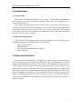
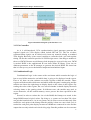
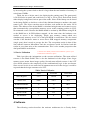
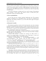
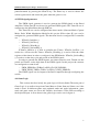
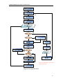
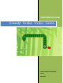
Embedded System
Greedy Snake Video Game
Yuqi Liu, Xiangyu Lian,Jing Zhang
LTH-Soc
2012-10-26
EDA385 Embedded System Design - Advanced Course
Abstract
This report documents the development of a classic video game—Greedy Snake. The project
is implemented based on the Digilent Nexys 3 FPGA Board, a USB Keyboard and a VGA monitor.
The game logic software was developed on the MicroBlaze processor which allows user to play
the game via an interrupt based Keyboard. The custom graphic accelerator compiled in VHDL
receives gaming information from MicroBlaze via PLB interface and generate the game video
output to the VGA screen.
2
EDA385 Embedded System Design - Advanced Course
Table
of
Contents
1 Introduction ............................................................................... 4
1.1 Greedy Snake ...................................................................................................... 4
1.2 Hardware Requirements ...................................................................................... 4
2 System Architecture ................................................................... 4
3 Hardware ................................................................................... 5
3.1 VGA Controller ................................................................................................... 6
3.2 Combinational Logic ........................................................................................... 6
3.3 Device Utilization ............................................................................................... 7
4 Software ..................................................................................... 7
4.1 Power-up Initialization ........................................................................................ 8
4.2 Keyboard Controller............................................................................................ 8
4.3 PWM signal generator......................................................................................... 9
4.4 Game Logic ......................................................................................................... 9
4.4.3 Game End ....................................................................................................... 12
4.5 Information Update ........................................................................................... 12
5 User Manual ............................................................................. 12
6 Conclusion ................................................................................ 13
3
EDA385 Embedded System Design - Advanced Course
1 Introduction
1.1 Greedy Snake
This project is required to develop a video game – Greedy Snake implementing
both software logic and a hardware accelerator. The game was designed to be a
real-time single player.
In the game, the movement direction of the snake is controlled by the player via
keyboard. The apple was produced randomly on the screen in the software. Points are
earned when the snake eats an apple. There are 4 levels of the game. The moving
speed of the snake increases as the level of difficulty increases. The game ends when
the snake hits the walls or himself.
1.2 Hardware Requirements
This project was developed and tested using Digilent Nexys 3 Board with a
SPARTAN6 FPGA and a USB Keyboard, VGA monitor.
Nexys 3 FPGA Board
USB Keyboard
VGA monitor (640x480 pixels @ 60 Hz)
Pmod Amplifier
2 System Architecture
Figure1 shows the architecture of the game, the whole system is divided into two
parts – software part and hardware part. The game logic is implemented in software
running on the Microblaze processor. The interface of USB keyboard and audio are
used to gather keyboard input and forward background audio, both of them will be
implemented in software. The position of the snake and the apple are calculated and
sent to the hardware accelerator through PLB by the Microblaze processor. The VGA
Display (Graphics Accelerator) is done in hardware which is solely for game video
display. The BRAM contains some pre-stored images such as the snake and fruit, etc.
All modules communicate with Microblaze through PLB and the block diagram is
shown in figure2.
4
EDA385 Embedded System Design - Advanced Course
This picture is not very easy to
understand. For instance, Microblaze
is still Hardware…
Figure1 System Architecture of the Greedy Snake Game
Figure2 Block Diagram of the Greedy Snake Game
This figure is a bit more
useful!
3 Hardware
Block diagram of the hardware core is shown in fig3. The core is basically
consisted of two parts. The VGA synchronization signal generator and the
combination control logic together with memory components.
5
EDA385 Embedded System Design - Advanced Course
Figure3 Detail block diagram of the hardware core
3.1 VGA Controller
As it is self-introduced, VGA synchronization signal generator generates the
required signals for VGA display which include HS and VS. The use of these
synchronization signals can be found easily from any material relating to standard
VGA display. Basically, it has several counters to count the clock cycle and regulate
timing. We use the controller provided in VLSI design course. One thing to mention is
the use of DCM. Because two different clock frequencies are used in the core, DCM
is needed. DCM is the sophisticated IP core from Xilinx IP library. Users can set
different parameters to the IP manager to generate the desired DCM. We found out
that it is always easy to use the buffered output and non-buffered input.
3.2 Combinational Logic
Combinational logic is the center of the accelerator which contains the logic of
how to read all the memories and which data is going to be displayed on the screen.
First of all, there are four software accessible registers within this module. Those
registers tells the module which state and which mode the game is undergoing and the
module can choose the right image to display based on the values in the register. By
reading the value of the register, the core can tell whether it should display the menu
selecting frame or the gaming frame. In different cases, the module may need to
access memories, all the needed memory access process has been specified in this
region.
Second, in order to reduce the size of the RAM, the bitmap was stored in the
image ROM instead of pixel values. By doing so, a system use less than 256 colors
can gain the benefit from it. As in our system, only 8 colors were used, thus only 3bits
needed for each point of the bitmap. But the penalty is that one extra clock cycle is
needed for each pixel point display because two ROMs are connected in series and the
output data can only refresh each clock rising edge. But this problem can be overcome
6
EDA385 Embedded System Design - Advanced Course
by increasing the system clock so that it is larger than the total number of memory in
serial times 25MHz.
Third, the use of object ram is for displaying the gaming panel. The game panel
is 28*28 blocks in square and each block is as big as 16*16 pixels. Each block would
either display background, fruit or part of the snake. Since all the bitmap can be found
in the image ROM, we decide to code all the different bitmaps to another code mark
named ‘part’. The object ram then stores all these code marks for the entire 28*28
blocks. The address of the object RAM is calculated using hcount and vcount in a way
that it automatically correspond the memory access to the scanning position in VGA.
No mismatch occurs. Because the RAM should be written by MicroBlaze using PLB,
so the RAM has to be PLB address mapped. At the same time, the hardware core
needed to access it for displaying. Single port memory cannot afford two
simultaneously memory access. So a dual port RAM is needed here. We also found
out that if the hardware wants to access those PLB mapped memory components
(single port), then it needs to occupy the bus. The occupation results in that all the
data transfer between MicroBlaze and the accelerator would be blocked and this
results in sever data miss of the communication. This is also another perspective that
dual port RAM is needed here.
3.3 Device Utilization
I assume this table presents the utilization just for your
hardware accelerator, right?
Table1 provides the information on the resource utilization. The most utilized
resource is the Block RAM. This is also the bottleneck of the design. Since larger
memory space means better image quality. Second most utilized resource is the LUT
slice which related to the complexity of the combinational logic in the accelerator.
Since several levels of case stated and if statement was used in the design, it could be
expected that the design consumes a lot LUT.
Table1 Device Utilization
Used
Available
Utilization
Slice Register
5377
18224
29%
Slice LUTs
6606
9112
72%
RAMB16BWERs
27
32
84%
RAMB8BWERs
5
64
7%
Bonded IOBs
125
232
53%
DCM GENs
1
4
25%
4 Software
The following section describes the software architecture for a Greedy Snake
7
EDA385 Embedded System Design - Advanced Course
game. The whole system software is implemented based on Microblaze, together with
several IP cores such as the PS/2 controller, PWM signal generator. PS/2 controller is
used to receive the keyboard codes from a USB keyboard for controlling the snake
move direction. The PWM signal generator is consisted of two timers for generating
the PWM signals.
The screen of the game is divided into 28 rows and 28 columns. The minimum
object resolution is 16x16 pixels. The software consists of mainly three parts:
Initialization, Game Logic and Data Update.
4.1 Power-up Initialization
At the game start, the software performs initialization part. The keyboard
controller is configured to be interrupting driven. The timers are configured into
PWM mode. The starting coordinates (x, y) of the snake and the apple are assigned
with a default value.
4.2 Keyboard Controller
The keyboard controller is used to receive and store the scan code from the
keyboard for controlling of the movement of a snake and choose the game levels. The
keyboard controller is configured in interrupt mode so it will not miss any pressed key.
The keyboard is connected to the Microblaze through PLB bus. Steps and functions
used to configure PS/2 controller are described below.
Functions XPs2_LookupConfig () and XPs2_CfgInitialize () are used to initialize
the PS/2 controller. XPs2_SelfTest () is used to do a self test for PS/2 controller.
XPs2_RecvByte () is used to read data.
Function XIntc_Initialize () initialize the interrupt and XIntc_Connect ()
connects the interrupt handler with interrupt source. XIntc_Start () choose the
interrupt mode and XIntc_Enable () enables the interrupter.
Functions Xil_ExceptionInit (), Xil_ExceptionRegisterHandler () and
Xil_ExceptionEnable () does initialize, setup and enable of exception mode
respectively. Function XPs2_SetHandler sets up the interrupt handler of PS/2.
At last functions XPs2_IntrEnable (), XPs2_IntrGlobalEnable () and
microblaze_enable_interrupts enables interrupt in PS/2, interrupt in the global system
and interrupt in MicroBlaze respectively.
The received scan codes are stored in buffers and function getkey () is used to
read the buffer. Functions iff0ignore () and ife0then () are called in function getkey ()
to ignore the break code from the keyboard and ignore the second key if two keys are
pressed at the same time. If no key is pressed the getkey () function produce a default
value to the game logic.
The players control the fourth moving directions of the snake through press the
keys (W/A/S/D/) of the keyboard. The W and S keys control the snake to move Up
and Down and choose the game levels. The A and D keys control the snake to move
Left and Right. The game can be suspended by pressing the ESC key and
8
EDA385 Embedded System Design - Advanced Course
paused/resumed by pressing the SPACE key. The Enter key is used to choose the
selected game mode and restart the game when the game is over.
4.3 PWM signal generator
The PWM signal generator is used to generate the PWM signals to the Pmod
Amplifier. Xilinx timer IP can be used to generate PWM signals. The Timer IP core is
connected to the MicroBlaze through PLB bus.
The Timer IP core can be configured into three modes (Generate Mode; Capture
Mode; Pulse Width Modulation Mode).In this project Xilinx timer IP core can be
configured to generate PWM signals. The functions used to configure PS/2 controller
are:
XTmrCtr_Initialize ()
XTmrCtr_SelfTest ()
XTmrCtr_WriteReg ()
XTmrCtr_SetLoadReg ()
XTmrCtr_Initialize () is used to initialize the Timers. XTmrCtr_SelfTest () is
used to do a self test for the Timers. XTmrCtr_WriteReg () is used to write the status
registers of the timers in order to configure it into PWM mode. XTmrCtr_SetLoadReg
() is used to set the duty cycle and period of the PWM signals.
In order to generate the PWM signals, two timers must be used. Timer0 sets the
period and Timer1 set the high time of the PWM signals. In this project the counters
are configured to count down.
PWM_PERIOD= (TLR0+2) ×PLB_CLOCK_PERIOD;
PWM_HIGH_TIME= (TLR1+2) ×PLB_CLOCK_PERIOD;
The PWM signals can be output to the Pmod Amplifier through configuring the
ucf file.
4.4 Game Logic
This section describes briefly the game logic of Greedy Snake.The main part of
Game Logic is an endless loop from Game Menu to Game Start and Game over if the
snake is dead. In different game steps updated snake and apple information, game
mode and game status are sent to the Graphic Accelerator via the PLB according to
the keyboard input. A flow chart for the game logic can be seen in figure 4.
9
EDA385 Embedded System Design - Advanced Course
Nice and informative with a flow
diagram like this.
Figure 4 Game logic flow chart
10
EDA385 Embedded System Design - Advanced Course
4.4.1 Game Menu
The Game Menu part shows the title of the game and provides four different
mode selections. The current targeted game mode and game status are sent to the
Graphic Accelerator through PLB bus.
The four selectable game modes are: easy, normal, hard and very hard. The
gamemenu () function is an endless loop which breaks until the ENTER key is
pressed and one of the game modes is selected.
4.4.2 Game Start
The game starts part first initialize the snake and apple and set game statues as
“playing”. The snake is initialized as five parts as beginning and moves from the
upper left side of the screen to the right. The snake has one life in this game.
Information about snake includes positions on the x and y axis, snake length, snake
life and snake part. Two 28*28 matrices are used to record the new position of the
snake and the last position of the snake. Both matrices are initialized with zeros at the
beginning. A random apple is generated by function rand (). After these steps
information of snake, apple and game status are sent to the Graphic Accelerator
through the PLB bus for displaying on a monitor.
After the initialization the gamestart () function begins an endless loop. In the
loop, a comparison of the two matrices is done to generate the updated data and send
the data through PLB to Graphic Accelerator. Then the function of audio output is
called to display the sound of snake movement. The life of the snake is checked to see
whether the snake is dead. If it is then the loop breaks and function gameend () is
called. Else the game continues. The existence of apple is checked, if the no apple
exists then generate an apple, else game continues. The getkey () function is called to
detect any key is pressed. If the key pressed is a direction key then the snake head
change position depending on current moving direction. The data of the part that
follows the snake`s head is also calculated here. As the snake has a head, a tail,
normal body and turning body, the snake part information is coded with 20 different
numbers for hardware to read four different snake pictures. If the key pressed is a
pause or quit key then the loop is paused or broken to gamemenu () function.
Otherwise the snake moves as default. Data of the rest of the snake is calculated
depending on the head and last snake information. After the data of the snake`s head
is calculated, the program detects whether the snake is eating an apple. If it is then the
snake length is increased by one and the date of the last part of the snake is calculated.
Else the snake data remain unchanged. Then detects the whether the snake has hit the
wall or eaten itself. If it has then the snake life is reduced to zero otherwise the value
remains one. Then delay function is called at the next step. The length of the delay
depends on the game mode selected. The last step in the loop is to update data in two
matrices. First the matrix with last snake information is written with data from the
matrix with current snake information. Then clear the matrix with current snake
information and write the calculated next snake information into it. Then the loop
goes back to the step that compares data in two matrices.
11
EDA385 Embedded System Design - Advanced Course
4.4.3 Game End
When the gameend () function is called, the game statues is changed and sent to
the Graphic Accelerator through PLB bus. The game over audio is displayed in this
function. There is also an endless loop in this function which break is the ENTER key
is pressed. The gamemenu () function is called after gameend () is over.
4.5 Information Update
The VGA screen is updated by the Graphics Accelerator based on the locations
information of the snake and the apple and game status information produced by the
MicroBlaze processor. In order to transfer these data, 4 32-bit registers and a 784*5
dual port RAM are used. MicroBlaze writes the data to these registers and RAM
through memory-mapped addressing method. When the data are updated, the contents
of these registers and RAM are updated with the latest data.
The dual port RAM concludes the information of the corresponding position of
the VGA screen.
The format of each of these registers is shown in the table2.
Table2 Data Format
Bits
31:25
24:16
15:8
7:0
Data
Game Mode
Game Status
5 User Manual
What does this mean? Why do you need 4 registers like
this?
The following components are required for playing this game.
Nexys 3 FPGA Board
USB Keyboard
VGA monitor (640x480 pixels @ 60 Hz)
Pmod Amplifier
Speaker
Following the below step to implement the Greedy Snake.
Make sure of the above hardware are connected with the Nexys 3 FPGA Board.
Download the download.bit file using Digilent Adept tool.
The player can control the movement of the snake according to the table3.
Table3 Game Control Code
Control Key
Action
W
Snake move Up
S
Snake move Down
A
Snake move Left
D
Snake move Right
Enter
Choose game level
ESC
Quit the game
SPACE
Pause/resume the game
When the game is over, press ENTER key to start the game. If the player does
12
EDA385 Embedded System Design - Advanced Course
not want to play the game, press ESC key to quit.
6 Conclusion
This project provides a great chance for us to learn more details about the
Embedded System Design. And also we got practical experience in
Hardware/Software co-design and integration. Furthermore, it greatly improved our
skill on how to solve the problems by ourselves. We also gained a lot of experience
on how to work as a group.
This conclusion just sounds like taken from the
course description. I would have liked to see some
of your own actual experiences.
Some pictures with the actual game would have been nice.
13
EDA385 Embedded System Design - Advanced Course
REFERENCES
[1]. Digilent Nexys 3 Board Reference Manual
[2]. XPS Timer datasheet.
[3]. Greedy Snake (video game).
[4]. Nexys3_PLB_BSB_Support datasheet.
A reference list is nice, but it has to be a bit
better specified.
14