1
v1.3 5-Jul-2012
BATCAN module
BATCAN
module for single B-sensor read-out
by CAN bus and CANopen
user manual & reference
v1.3, 5 July 2012
Henk Boterenbrood
NIKHEF, Amsterdam, NL
ABSTRACT
This document describes the BATCAN module, a plug-on for the NIKHEF B-sensor module
providing it with a CAN-bus interface. It also describes the firmware features including the
CANopen message protocol and CANopen Object Dictionary.
1
v1.3 5-Jul-2012
BATCAN module
Table of Contents
1
INTRODUCTION AND OVERVIEW............................................................................. 3
2
CONNECTORS AND INTERFACES ............................................................................. 4
3
INITIALISATION ............................................................................................................. 7
4
NODE GUARDING AND LIFE GUARDING................................................................ 8
5
B-SENSOR DATA READ-OUT ..................................................................................... 10
5.1
5.2
5.3
5.4
6
INTRODUCTION ........................................................................................................................ 10
B-SENSOR DATA ...................................................................................................................... 11
ADC DATA CONVERSION ........................................................................................................ 13
B-SENSOR SERIAL NUMBER..................................................................................................... 14
CONFIGURATION STORAGE .................................................................................... 16
6.1
6.2
STORING PARAMETERS AND SETTINGS ................................................................................... 16
EEPROM MEMORY MAP ........................................................................................................ 17
7
UPGRADING THE FIRMWARE.................................................................................. 18
8
BATCAN OBJECT DICTIONARY............................................................................... 19
9
EMERGENCY OBJECTS .............................................................................................. 26
REFERENCES........................................................................................................................ 28
APPENDIX A.
NTC TEMPERATURE SENSOR DATA ............................................... 29
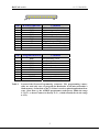
Version History
Version Date
Comments
1.3
5 Jul 2012
Describes firmware version "BC11.0002".
Added Object 5380h and 2500h, sub 29-37.
1.2a
9 Feb 2011
Fixed some errors in schematic in Figure 1.
1.2
4 Feb 2010
1.1
26 Sep 2008
1.0
14 Aug 2008
Table 1.
Describes firmware version "BC11.0000".
Additional Objects for compatibility with BATsCAN firmware for
mBATCAN modules.
Added Object 2800h to OD listing, was missing.
Object 2910h renamed to 29F0h.
Describes firmware version "BC10.0003".
Additional Objects 2900h, sub 3 and 2910h.
New pictures; some changes to text.
Describes firmware version "BC10.0000".
Document change record (latest change first).
2
v1.3 5-Jul-2012
BATCAN module
1 Introduction and Overview
The BATCAN module is a module that plugs directly on the NIKHEF B-sensor module [1],
providing a CAN interface for reading out the B-sensor module. The BATCAN firmware is
based on the firmware used in the ATLAS MDT-DCS module [2], and is –as far as the readout of a single B-sensor module is concerned– completely compatible with that module.
In addition the BATCAN module may be used as a component in the so-called BsCAN3
system [3], in which a number of BATCAN and mBATCAN [4] modules make up a B-field
sensor measurement system with multiple B-sensor modules, in closely spaced groups read
out by an mBATCAN module and/or individual modules typically spaced further apart, each
read out by a BATCAN module, all connecting to a single CAN bus which can extend to over
100 m in length.
Some additions have been made to the firmware in order to make the BATCAN module
compatible with the mBATCAN module from the CANopen point-of-view.
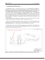
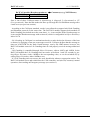
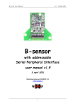
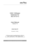
A schematic of the BATCAN module is shown in Figure 1. The central component of the
module is an Atmel AT90CAN64 microcontroller with integrated CAN-controller (hence the
name BATCAN: B-sensor readout module with ATmel CAN microcontroller)
The BATCAN module controls and monitors the B-sensor module ADC and provides readout of the B-sensor data via a CAN bus. The CANopen protocol [5] [6] is used as high-level
communication protocol standard on the bus.
NB: pull-up resistor on 1-Wire required! (CON1, pin 8)
4
2
Figure 1. Schematic of the BATCAN module (NB: modified original in driver/coupler area).
3
v1.3 5-Jul-2012
BATCAN module
2 Connectors and Interfaces
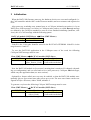
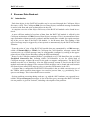
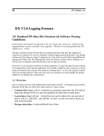
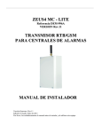
The pictures in Figure 2 show the BATCAN module and its external interfaces, and plugged
onto a B-sensor module.
space for optional JTAG
debug connector
CAN-bus connector
B-sensor connector
Red LED
Green LED
Figure 2. The BATCAN module (top left & right), and plugged onto a B-sensor module
(bottom left & right).
4
v1.3 5-Jul-2012
BATCAN module
pin 1
Pin
B-sensor function
1
2
3
4
5
6
7
8
9
10
SCLK
GND
SDI
GND
SDO
GND
CS
ID
–
V+
Pin
Program function
1
2
3
4
5
6
7
8
9
10
SCK
GND
PDI
GND
PDO
GND
–
–
RESET
V+
Table 2.
10
Comment
SPI Serial Clock (to ADC)
SPI Serial Data In (to ADC)
SPI Serial Data Out (from ADC)
Chip Select (to ADC)
1-Wire interface (to ID-chip)
from CAN-connector (pin 8)
Comment
Programming Clock
Program Data In
Program Data Out
Reset to the AT90CAN micro
from CAN-connector (pin 8)
Layout of the B-sensor/Programming connector. The programming connections are used only once, to program the Bootloader in the microcontroller’s
flash memory; from then on the CAN bus is used to upload application firmware. (Note that e.g. the AVRISP programmer needs power within the range
2.7-5.5V, so do not connect it directly to V+, which normally lies in the range
6-12V).
5
v1.3 5-Jul-2012
BATCAN module
1
9
Table 3.
2
10
function
pin
pin
function
not connected
1
2
not connected (CAN-GND)
CAN-L
3
4
CAN-H
CAN-GND
5
6
+V (6-12V)
GND
7
8
CAN-POWER (6-12V)
CAN-SHIELD
9
10
not connected
Layout of the BATCAN CAN connector. CAN-POWER powers the CANdriver part of the BATCAN module. +V powers the rest of the BATCAN
module as well as the B-sensor module.
The BATCAN module features two LEDs to indicate the status of the module, a red one and
a green one (see Figure 2). The green LED is on when the module has properly initialized and
the firmware is running; it blinks briefly when CAN-messages are received or sent. The red
LED comes on when there is a problem with (reading out) the B-sensor.
The BATCAN module's serial number, which it has been given after production testing, can
be read out remotely (see Object Dictionary index 3100h in section 8).
The module's CAN node identifier is stored in EEPROM and can be changed remotely (see
Object Dictionary index 3300h and 3301h in section 8).
6
v1.3 5-Jul-2012
BATCAN module
3 Initialisation
When the BATCAN firmware starts up, the hardware devices are reset and configured (i.e.
the CAN-controller and the ADC on the B-sensor module) and error counters and registers are
reset.
After power-up, watchdog reset, manual reset or a CANopen initiated reset action (i.e. by an
NMT Reset-Node message, see below) a CANopen node sends a so-called Boot-up message
(as defined by the CANopen standard) as soon as it has finished initializing (hardware, software); this is a CAN-message with the following syntax:
BATCAN module (NMT-Slave)
COB-ID
700h + NodeID
→
Host (NMT-Master)
Data Byte 0
0
NodeID is the CAN node identifier stored in the BATCAN’s EEPROM. NodeID is in the
range between 1 and 127.
To start the BATCAN application in the CANopen sense of the word, the following
CANopen NMT message must be sent:
Host (NMT-Master) → BATCAN module (NMT-Slave)
COB-ID
000h
Data Byte 0
01h
(Start_Remote_Node)
There is no reply to this message.
Data Byte 1
NodeID or 0
(0: all nodes on the bus)
Now the BATCAN module is Operational, meaning that it monitors I/O channels (depending on configuration) and can send and receive (and processes) CANopen PDO messages,
which carry the application data (see next sections).
Optionally a feature called auto-start may be enabled, so that the BATCAN module automatically goes to Operational state after power-up or reset. The auto-start feature can be configured in Object Dictionary index 3200h, subindex 2.
To generate a soft reset the following CANopen NMT message must be sent:
Host (NMT-Master) → BATCAN module (NMT-Slave)
COB-ID
000h
Data Byte 0
81h
(Reset_Node)
Again, there is no reply to this message.
Data Byte 1
NodeID or 0
(0: all nodes on the bus)
7
v1.3 5-Jul-2012
BATCAN module
Note that at power-up it is the Bootloader application firmware that becomes active first and
is in control of the BATCAN module; the Bootloader reports its presence by sending the following Emergency message (see also section 7):
Bootloader
COB-ID
080h +
NodeID
→
Host
Byte 0-1
Emergency
Error Code
(00h 50h)
Byte 2
Error Register
(Object 1001h)
(80h)
Byte 3-7
Manufacturer specific error field
(FEh 00h 64h ZZh 00h)
(ZZh = MCUSR)
(MCUSR = MCU Status Register; for details see section 9 or the AT90CANxx datasheet).
Having the Bootloader activate at power-up guarantees that it is always possible to upload
new application software to the module, even when the application currently programmed is
faulty or corrupted.
After about 4 seconds the Bootloader automatically jumps to the application. Alternatively,
the Bootloader starts the application immediately, if it receives an NMT Reset-Node message
–as shown above- within this period.
4 Node Guarding and Life Guarding
Node Guarding in CANopen is a mechanism whereby an NMT-master checks the state of
other nodes on the bus, at regular intervals. It can do this in one of two different ways:
1. The master sends a Remote Transmission Request (RTR) for the Node Guard message,
to each node on the bus, in turn; a node that receives the RTR, sends the Node Guard
message, which contains one data byte indicating the (CANopen) state of the node, as
well as a toggle bit. If a node does not reply the master should signal this to the higherlevel software and/or take appropriate action.
The RTR for the Node Guard message looks like this (a Remote Frame, so the CANmessage has no data bytes):
Host (NMT-Master)
→
BATCAN module (NMT-Slave)
COB-ID
700h + NodeID
The reply Node Guard message from a node looks like this:
BATCAN module (NMT-Slave)
COB-ID
700h + NodeID
→
Host (NMT-Master)
DataByte 0
bit 7: toggle bit,
bit 6-0: state
2. Each node on the bus sends a Heartbeat message at regular intervals; typically, the
NMT-master monitors these messages and keeps a time-out period for each node. The
master detects nodes that stop sending their Heartbeat messages and should signal this
to the higher-level software and/or take appropriate action.
A Heartbeat message looks like this:
8
v1.3 5-Jul-2012
BATCAN module
BATCAN module (Heartbeat producer)
COB-ID
700h + NodeID
→
Consumer(s) (e.g. NMT-Master)
DataByte 0
State
State is one of these CANopen states: 0 (Initializing), 4 (Stopped), 5 (Operational) or 127
(Pre-operational). Note that this makes the Boot-up message the first Heartbeat message after
a node reset (see previous section).
According to the CANopen standard, a node is not allowed to support both Node Guarding
and Heartbeat protocols at the same time. The BATCAN module supports both methods of
Node Guarding (but indeed not at the same time), i.e. it can send the Node Guard message or
it can send the Heartbeat message with an interval, which is configurable in Object Dictionary
index 1017h.
Life Guarding in CANopen is a mechanism whereby a node checks the aliveness of the host
or master, by applying a time-out on messages received. CANopen defines that the message to
time-out is the RTR for the Node Guard message, sent by the NMT-master; however, the
BATCAN module resets its Life Guarding timer at each properly received message addressed
to it.
Life Guarding is controlled through Object Dictionary objects 100Ch and 100Dh. In the
BATCAN module the Life Guarding time-out can be set between 1 and 255 seconds, by setting Object Dictionary index 100Dh to the corresponding value, or can be switched off, by
setting Object Dictionary index 100Dh to zero.
If a Life Guarding time-out occurs, the node should take whatever appropriate action. The
BATCAN module resets and reinitializes the CAN-controller, and (tries to) resume(s) normal
operation, after sending an Emergency message (see section 9).
9
v1.3 5-Jul-2012
BATCAN module
5 B-sensor Data Read-out
5.1
Introduction
Each data object in the BATCAN module can be accessed through the CANopen Object
Dictionary (OD). The CANopen SDO (Service Data Object) confirmed message mechanism
is used to read from and write to data objects in the OD.
A complete overview of the Object Dictionary of the BATCAN module can be found in section 8.
A more efficient method of read-out of data from the BATCAN module is offered by the
CANopen mechanism of PDO (Process Data Object) messages. This is an unconfirmed message mechanism without protocol overhead, and thus much more suitable for regular monitoring of the process data of the BATCAN module, i.e. the B-sensor data. The sending of this
type of message may be triggered by a host system or autonomously by the BATCAN module
firmware.
From the point of view of the BATCAN module data are transmitted by a PDO message,
called a Transmit-PDO (or TPDO). In CANopen the CAN-identifier, message content and
transmission type of PDO messages may be configurable (configure by writing to the appropriate objects in the Object Dictionary using the SDO mechanism).
However, the CANopen standard defines a predefined set of CAN-identifiers (the so-called
Predefined Connection Set), defining which CAN-identifier to use for which kind of
CANopen message, without the need for the node to support configuration. The BATCAN
module uses this set of identifiers. Also the PDO message content is fixed in the BATCAN
module and cannot be changed. The content of PDO messages can be found and read from the
OD from objects called PDO mapping objects (stored at fixed entries in the OD).
A feature that is configurable on the BATCAN module is the so-called transmission type of
the TPDOs, which controls what triggers it to send its 'process' data, e.g. periodically, on request or on-change. This is described in a next section.
Serious problems occurring during read-out, e.g. with the ADC hardware, are reported in socalled CANopen Emergency messages. A list of the Emergency messages the BATCAN module can produce is given in section 9, including a description of the problem.
10
v1.3 5-Jul-2012
BATCAN module
5.2
B-sensor Data
The BATCAN module sends one PDO message containing 5 bytes for each B-sensor input
and four of the B-sensor’s inputs are read: Hall sensors H1, H2 and H3 and the temperature
sensor. The CAN-identifier used for this PDO is the so-called 4th-transmit-PDO (TPDO4) of
the CANopen Predefined Connection Set.
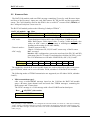
The BATCAN module produces the following 5-databyte TPDO4 1:
BATCAN module
COB-ID
480h + NodeID
with:
ADC value:
Channel number:
ADC-config:
BIT
Meaning
→
Host
Data Byte 0
Channel number
Data Byte 1
ADC-config
Data Byte 2-4
24-bit ADC value
Signed/unsigned 24-bits ADC value, LSB in byte 2, MSB in byte 4.
Note: Hall sensors: 24-bit signed value; T-sensor: 24-bit unsigned value
(either an ADC count or a temperature in millidegrees centigrade depending on the setting of OD index 4400h),
Number between 0 and 3.
Chan 0-3: Hall sensor H1, H2, H3 and T-sensor resp. of the B-sensor
bit 7: not used.
bits 6-0: ADC configuration: conversion word rate (bits W0, W1 and W2),
gain range (bits G0, G1 and G2) and unipolar or bipolar (bit U/B); see below. For definitions see OD index 2500h/2501h, sub 2,3,4,5,6 and 7.
7
-
6
W2
5
W1
4
W0
3
G2
2
G1
1
G0
0
U/B
The method by which the B-sensor module inputs are read out depends on the transmissiontype of TPDO4, which can be set in OD index 1803h, subindex 2 of the BATCAN module.
The following modes of TPDO2 transmission are supported (see OD index 1803h, subindex
2 and 5):
•
PDO transmission type 1:
after every so-called SYNC message issued on the CAN-bus the BATCAN module
starts a B-sensor input channel scan and sends four TPDO4 messages, containing the
Hall-sensors and T-sensor data.
The SYNC message is a CAN-message with a fixed COB-ID and no data bytes:
Host
→
all (SYNC-)slave nodes
COB-ID
080h
1
NB: optionally a 6-byte TPDO4 can be configured in OD index 4500h, see section 8; a data byte containing
‘index’ value 0 is inserted on data byte position 0 of the PDO; this makes the BATCAN’s PDO message compatible with PDO messages with B-sensor data from nodes with BATsCAN firmware used in mBATCAN
nodes, see [4].
11
v1.3 5-Jul-2012
BATCAN module
Note that all nodes that have PDOs configured to respond to a SYNC message will respond to the SYNC, which is a broadcast message.
•
PDO transmission type 255:
after every so-called Remote Transmission Request (RTR) for TPDO4 the BATCAN
module starts a B-sensor input channel scan and sends four TPDO4 messages, containing
the Hall-sensors and T-sensor data. The Remote Frame CAN-message that constitutes
this RTR has no data bytes and looks like this:
Host
→
BATCAN module
COB-ID
280h+NodeID
Note that an RTR is sent to and received/processed by only one particular node.
•
Event Timer > 0:
If TPDO4’s event timer (OD index 1803h, sub 5) is set to a value unequal to zero (event
timer is expressed in units of 1 s and must be <=255) the BATCAN module automatically starts a B-sensor input channel scan periodically, triggered by a timer (in this mode
an RTR or SYNC message also triggers an input scan, depending on the transmission
mode as shown above).
Optionally a reset and calibration sequence can be done before each B-sensor ADC channel
scan. This feature can be enabled via OD index 2700h (useful perhaps for increasing radiation
tolerance).
Individual B-sensor module channels (there are actually 7 inputs) can be read out using
CANopen SDO messages by reading from OD index 4200h (see OD tables for a description
of each individual channel).
12
v1.3 5-Jul-2012
BATCAN module
5.3
ADC Data Conversion
The interpretation of the Hall sensor ADC values and conversion to physical values will be
done offline using a set of calibration tables for each individual B-sensor module and some
dedicated software (available from Felix Bergsma at CERN).
The B-sensor module's T-sensor is an NTC, Thermometrics type number DC95F502W, with
a nominal resistance of 5 kΩ. See Appendix A for datasheet and temperature data of the NTC.
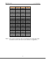
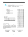
Table 4 shows a list of resistance values RNTC for this NTC at different temperatures, and
the resulting B-sensor module ADC input voltage. In the shaded part of the table (between 0º
and 70º C) the precision is ±0.2º C.
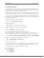
The ADC input voltage VNTC can be expressed as:
VNTC = Vref - VccRNTC / (RNTC + Rref)
which can be rewritten as:
RNTC = Rref (Vref - VNTC) / (VNTC + Vcc - Vref)
With Rref = 23.2 kΩ, Vcc = 5 V and Vref = 2.5 V this results in:
RNTC = 23200 (2.5 - VNTC) / (VNTC + 2.5)
VNTC is the voltage value calculated from the 24-bit ADC value A.
The ADC input has been calibrated to give A=0 (000000h) at 0 ºC (i.e. at 0.4315 V) and
A=16777215 (0xFFFFFF) at 100 ºC (i.e. at 2.4275 V), so that VNTC can be expressed as:
VNTC = 0.4315 + (2.4275 - 0.4315)A/FFFFFFh = 0.4315 + 1.996A/FFFFFFh
So RNTC can be calculated directly from ADC value A as follows:
RNTC = 23200 (2.0685 - a) / (2.9315 + a)
with a = 1.996 A / 16777215.
To calculate temperature T (in ºC, in the range from 0 to 100 ºC) of the NTC from NTC resistance value RNTC (in Ω), the following approximation equation (see Appendix A) is used:
T = ( 1.0 / (a + b ln(r) + c ( ln(r) )2 + d ( ln(r) )3 ) ) - 273.15
with r = RNTC/5000,
and a = 3.3538646E-03
b = 2.5654090E-04
c = 1.9243889E-06
d = 1.0969244E-07
13
v1.3 5-Jul-2012
BATCAN module
when 68.600 >= r > 3.274
or
a = 3.3540154E-03
b = 2.5627725E-04
c = 2.0829210E-06
d = 7.3003206E-08
when 3.274 >= r > 0.36036
or
a = 3.3539264E-03
b = 2.5609446E-04
c = 1.9621987E-06
d = 4.6045930E-08
when 0.36036 >= r >= 0.06831
or
a = 3.3368620E-03
b = 2.4057263E-04
c = -2.6687093E-06
d = -4.0719355E-07
when 0.06831 >= r >= 0.01872
(i.e. when -50º C <= T < 0º C),
(i.e. when 0º C <= T < 50º C),
(i.e. when 50º C <= T < 100º C).
(i.e. when 100º C <= T < 150º C).
The conversion functions above are applied by the BATCAN firmware to the ADC readings
when temperature read-out is set to millidegrees centigrade, which is the default.
5.4
B-sensor Identification Number
Each B-sensor module comes equipped with a unique identification number, which is factory-lasered in the on-board Dallas DS2405 device.
The 64-bit (8-byte) number is used to uniquely identify each module, for instance to match
each module with its calibration data, which are kept elsewhere off-line.
The identification number of the B-sensor modules can be read from OD Object 2900h. The
least significant 4 bytes are read from subindex 1 and the most significant 4 bytes from subindex 2. The least- or most-significant sets of 4 bytes can be read in any order.
The layout of the 64-bit ID number is as shown below:
8-bit CRC Code
MSB
LSB
byte 7
48-bit Identification Number
MSB
LSB
byte 6-4
byte 3-1
↓
↓
OD index 2900h, subindex 2
8-bit Family Code (01h)
MSB
LSB
byte 0
↓
↓
OD index 2900h, subindex 1
Figure 3. B-sensor 64-bit ID Number and its mapping to Object Dictionary (OD) objects.
The BATCAN module checks the correctness of the identification number CRC when OD
Object 2900h is read, so a valid reply implies the CRC was correct: the host does not need to
recalculate the number’s CRC.
14
v1.3 5-Jul-2012
BATCAN module
AIN4
(ADC)
[C]
Nor malized
Resistance
Ohm
Ohm
Volt
-50
68.60
343000.00
-2.1832
-45
48.16
240800.00
-2.0606
-40
34.23
171150.00
-1.9031
-35
24.62
123100.00
-1.7071
-30
17.91
89550.00
-1.4712
-25
13.17
65850.00
-1.1974
-20
9.782
48910.00
-0.8913
-15
7.339
36695.00
-0.5633
-10
5.558
27790.00
-0.2250
-5
4.247
21235.00
0.1106
0
3.274
16370.00
0.4315
5
2.544
12720.00
0.7294
10
1.992
9960.00
0.9982
15
1.572
7860.00
1.2347
20
1.250
6250.00
1.4389
25
1.000
5000.00
1.6135
30
0.8056
4028.00
1.7603
35
0.6530
3265.00
1.8831
40
0.5326
2663.00
1.9852
45
0.4369
2184.50
2.0697
50
0.3604
1802.00
2.1396
55
0.2989
1494.50
2.1974
60
0.2491
1245.50
2.2452
65
0.2087
1043.50
2.2848
70
0.1756
878.00
2.3177
75
0.1485
742.50
2.3449
80
0.1261
630.50
2.3677
85
0.1075
537.50
2.3868
90
0.09209
460.45
2.4027
95
0.07916
395.80
2.4161
100
0.06831
341.55
2.4275
105
0.05916
295.80
2.4371
Temperat ure
Resistance
Table 4. NTC resistance/temperature table, and resulting B-sensor ADC input voltage
(Normalized resistance table taken from the datasheet, see Appendix A).
15
v1.3 5-Jul-2012
BATCAN module
6 Configuration Storage
6.1
Storing Parameters and Settings
Parameters and settings can be stored permanently onboard in non-volatile memory
(EEPROM) by writing string "save" to OD index 1010h. The SDO mechanism is used to accomplish this, using the following message:
Host
→
BATCAN module
Data Byte
COB-ID
0
1
2
600h +
0x23
0x10
0x10
NodeID
3
subindex
4
73h
('s')
5
61h
('a')
6
76h
('v')
7
65h
('e')
with OD index 1010h in byte 1+2 and subindex in byte 3 with subindex:
= 1: store all parameters (as listed for subindex 2 and 3).
= 2: store communication parameters (concerning CAN, PDOs and Node- and Life Guarding).
= 3: store application parameters (concerning ADCs, Digital I/O and JTAG).
= 4: see next section.
If the store-operation succeeded the BATCAN module sends the following reply:
BATCAN module → Host
Data Byte
COB-ID
0
1
580h +
0x60
0x10
NodeID
2
0x10
3
subindex
4
–
5
–
6-7
–
If the store-operation did not succeed the BATCAN module sends the following reply (SDO
Abort Domain Transfer, error reason: ‘hardware fault’ (for more details see [5])):
BATCAN module → Host
Data Byte
COB-ID
0
1
2
580h +
80h
10h
10h
NodeID
3
Subindex
4
0
5
0
6
6
(Error Code)
7
6
(Error Class)
Parameters can be reset to their default values (by invalidating the corresponding contents of
the EEPROM) by writing to OD index 1011h, using this time the string "load" (6Ch, 6Fh,
61h, 64h) in bytes 4 to 7 of the SDO. Note that the default values take effect only after a subsequent reset of the module. The default parameter values are listed in the OD tables in section 8.
The Object Dictionary tables in section 8 show which settings can be stored in EEPROM:
these are marked by an asterisk (*) in the first column
16
v1.3 5-Jul-2012
BATCAN module
(Note that storage of the BATCAN Serial Number is handled separately).
6.2
EEPROM Memory Map
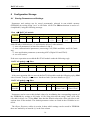
Table 5 below details the layout of the AT90CAN64 microcontroller EEPROM usage by the
BATCAN application firmware.
EEPROM
not used
ADDR
0000h
0001h
BATCAN
configuration
parameters
00A0h
00A1h
Rad-tolerant
working copy
of global
settings and
parameters
not used
BATCAN
Serial
Number
Node-ID (opt)
00FEh
00FFh
0100h
DESCRIPTION
Holds permanently saved application configuration and settings, stored in up to 8 blocks of
up to 16 bytes each; includes a CRC checksum
for each data block.
Holds a copy of most application configuration and settings and some other parameters
that don't change very often; parameters are
reread from EEPROM each time before being
used; this is an optional feature to counter effects of SEE (Single Event Upset).
Holds the module’s Serial Number given to it
at production time; serves to uniquely identify
the module.
0106h
0107h
0108h
not used
The 'Node-ID' location contains the CAN
Node-ID for the module; if the location does
not contain a valid number (1<=val<=127) 31
will be used.
0FFFh
Table 5.
AT90CAN64 microcontroller EEPROM memory map of the BATCAN application firmware.
17
v1.3 5-Jul-2012
BATCAN module
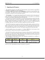
7 Upgrading the Firmware
The application program in the BATCAN microcontroller can be replaced or upgraded by
uploading new program code via the CAN-bus.
A Windows application program called ELMBloader is available for performing this firmware upgrade. The upgrade process leaves the EEPROM intact, in other words: all existing
configuration settings are preserved during an upgrade.
The Bootloader [7] is an application program stored in a separate section of the microcontroller flash memory. It handles the firmware upgrade process, receiving series of CAN(open)
messages containing the programming instructions and code.
After power-up of the BATCAN module, it is the Bootloader, that takes control of the module initially. After about 4 seconds the Bootloader automatically jumps to the start of the
BATCAN application program, or immediately after it receives a CANopen NMT Reset-Node
message. However, the Bootloader remains in control if it receives a valid programming
command within those 4 seconds. The firmware upgrade process may then begin.
The BATCAN application program can transfer control of the module explicitly to the Bootloader, when one writes any value to the 8-bit object 5E00h in the Object Dictionary of the
BATCAN application. In this case the Bootloader does not automatically jump to the BATCAN application program after 4 seconds. The firmware upgrade process may now begin.
After the upgrade process, the reception of a CANopen NMT Reset-Node message causes
the Bootloader to jump to the start of the new application program.
If the BATCAN module sends an Emergency message as shown below, it signifies that the
Bootloader is in control of the module. Note that the same Emergency message is also sent as
the first message after power-up, when the Bootloader is in control for the first 4 seconds after
power-up, before jumping to the application program.
The Bootloader can be forced to jump to the application immediately, by sending it a
CANopen NMT Reset-Node message.
COB-ID
080h +
NodeID
Byte 0-1
Emergency
Error Code
(00h 50h)
Byte 2
Error Register
(Object 1001h)
(80h)
Byte 3-7
Manufacturer specific error field
(5 bytes: FEh,80h,64h,ZZh,00h,
with ZZh = MCUSR)
(MCUSR = MCU Status Register contents; for details see section 9).
18
v1.3 5-Jul-2012
BATCAN module
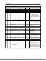
8 BATCAN Object Dictionary
The values of objects marked with ∗ in the Index column can be stored permanently in
EEPROM. They are retrieved from EEPROM at reset and power-up.
Communication Profile Area (BATCAN)
Index
(hex)
Sub
Index
Description
Data/
Object
Attr
1000
-
Device type
U32
RO
00000000h
1001
1002
-
Error register
Manufacturer status reg
U8
U32
RO
RO
0
0
1008
1009
100A
0
VisStr
VisStr
VisStr
RO
RO
RO
"BATC"
"bc10"
"BC11"
1
Manufacturer device name
Manufacturer hw version
Manufacturer software
version
minor version number
VisStr
RO
"0002"
-
Guard time [ms]
Life time factor
U16
U8
RO
RW
1000
0
Store parameters
Highest index supported
Save all parameters
Save communication parameters
Save application par's
Array
U8
U32
U32
RO
RW
RW
3
1
1
U32
RW
1
Restore default parameters
Array
0
1
Highest index supported
Restore all parameters
U8
U32
RO
RW
3
1
2
Restore communication
parameters
Restore application par's
U32
RW
1
U32
RW
1
Producer Heartbeat Time
[1 s]
U16
RW
0
Identity
Number of entries
Vendor ID
Record
1..4
U32
RO
RO
1
12345678h
100C
100D
*
1010
0
1
2
3
1011
3
1017
*
-
1018
0
1
1
Default
Comment
Meaning: no specific device profile
1
(see footnote)
= BATCAN module
= BATCAN v1
BATCAN application v1.1.2
= 1 second
Life Guarding timeout in seconds;
0 → no life guarding timeout
Save stuff in onboard EEPROM
Read: 1; Write "save": store all
Read: 1; Write "save": store
PDO par's, Life time factor, …
Read: 1; Write "save": store
ADCs config, …
Invalidate stuff in onboard
EEPROM; use defaults
Read: 1; Write "load": invalidate
all parameters stored
Read: 1; Write "load": invalidate stored PDO par's, etc.
Read: 1; Write "load": invalidate stored ADCs config, etc.
In units of seconds (but <=255 !),
(NB: actually should be in ms according to CANopen!);
0 → Heartbeat is disabled
Mandatory CANopen object
to be ordered from CiA
Manufacturer Status Register: byte1 = B-sensor ADC. (byte1 for compatibility with MDT-DCS app)
Status byte/nibble: 01: ADC reset error, 02: ADC calibration error, 04: ADC conversion time-out, FF: ADC
absent / not used.
19
v1.3 5-Jul-2012
BATCAN module
Communication Profile Area (BATCAN) (continued…)
Index
(hex)
Sub
Index
Description
Data/
Object
0
1
4th Transmit PDO par's
Number of entries
COB-ID used by PDO
2
3
4
5
0
1803
*
*
1A03
1
2
Attr
Default
Record
U8
U32
RO
RO
Transmission type
Inhibit time [100 μs]
Not used
Event timer [1 s]
U8
U16
U8
U16
RW
RO
RO
RW
5
480h +
NodeID
1
0
0
0
4th Transmit PDO mapping
Number of entries
Record
U8
RO
2
B-sensor ADC channel
number
24-bit analogue input
U32
RO
42000008h
U32
RO
420x0x20h
Comment
Data type = PDOCommPar
20
According to CANopen Predefined Connection Set
Only 1 and 255 allowed
not used
In units of secs, must be <= 255;
active for all transmission-types!
Data type = PDOMapping
should be 255 for MuxPDO, but
this is not a CANopen MPDO…
actually not allowed, but…
OD-index 4200/4201,subindex x,
Analogue inputs, multiplexed,
size = 32 bits
v1.3 5-Jul-2012
BATCAN module
Manufacturer-specific Profile Area (BATCAN) (continued…)
Index
(hex)
Sub
Index
Description
Data/
Object
Attr
Default
8
B-sensor ADC-config
Number of entries
Number of input channels
Conversion Word Rate
Hall
Input Voltage Range Hall
Unipolar/Bipolar
Measurement Mode Hall
Conversion Word Rate
Temp
Input Voltage Range Temp
Unipolar/Bipolar
Measurement Mode Temp
Power Save Mode
Record
U8
U8
U8
RO
RO
RW
22
7
0
3-bit code 1
U8
U8
RW
RW
0
0
3-bit code 2
0 = bipolar, 1 = unipolar
U8
RW
0
3-bit code 1
U8
U8
RW
RW
5
1
3-bit code 2
0 = bipolar, 1 = unipolar
Bool
WO
Configuration Register
Offset Register #1
Gain Register #1
Offset Register #2
Gain Register #2
Offset Register #3
Gain Register #3
Offset Register #4
Gain Register #4
Channel-Setup Register #1
U32
U32
U32
U32
U32
U32
U32
U32
U32
U32
RW
RW
RW
RW
RW
RW
RW
RW
RW
RW
19
Channel-Setup Register #2
U32
RW
20
Channel-Setup Register #3
U32
RW
21
Channel-Setup Register #4
U32
RW
22
SPI SCLK signal high
period (opto-coupler delay)
---
U8
RW
10
1 = set ADC to power save mode
0 = take ADC out of this mode
CS5524 Config Register
CS5524 physical channel AIN1
CS5524 physical channel AIN1
CS5524 physical channel AIN2
CS5524 physical channel AIN2
CS5524 physical channel AIN3
CS5524 physical channel AIN3
CS5524 physical channel AIN4
CS5524 physical channel AIN4
LC 1 (12-bits) in lower 2 bytes,
LC 2 (12-bits) in upper 2 bytes
LC 3 (12-bits) in lower 2 bytes,
LC 4 (12-bits) in upper 2 bytes
LC 5 (12-bits) in lower 2 bytes,
LC 6 (12-bits) in upper 2 bytes
LC 7 (12-bits) in lower 2 bytes,
LC 8 (12-bits) in upper 2 bytes
in μs, 10 <= value <= 255
9/29 3
10/303
11/313
12/323
13/333
14/343
15/353
16/363
17/373
18
---
---
2500
*
0
1
2
*
*
3
4
*
5
*
*
6
7
*
23-28
Comment
CS5524 24-bit ADC
1
000: 15.0 Hz,
100: 101.1 Hz,
001: 30.0 Hz,
101: 1.88Hz,
010: 61.6 Hz,
110: 3.76 Hz,
011: 84.5 Hz,
111: 7.51 Hz
2
000: 100 mV,
001: 55 mV,
010: 25 mV,
011: 1 V,
3
Entries for BATsCAN firmware compatibility.
21
reserved
100: 5 V,
101: 2.5 V
v1.3 5-Jul-2012
BATCAN module
Manufacturer-specific Profile Area (BATCAN)
Index
(hex)
Sub
Index
2600
(continued…)
Description
Data/
Object
Attr
-
ADC-reset-and-calibrate
B-sensor
U8
WO
2700
*
-
ADC-reset-and-calibrate
before every scan cycle
Bool
RW
0
If =1 a reset/calibration sequence
is performed before every Bsensor ADC input channel scan
2800
*
-
B-sensor presence mask
Bool
RW
1
Can only be 1 (B-sensor present,
default) or 0 (B-sensor absent)
B-sensor 64-bit
identification number
Record
Number of entries
Lower 4 bytes
Upperb 4 bytes
Read ID and toggle
DS2405 output (using
‘Match ROM’ command)
U8
U32
U32
U32
ID-chip search
Record
Initialize ID-chip search
Next ID: first 4 bytes
Second 4 bytes of ID found
Next ID ‘active-only’:
first 4 bytes
Second 4 bytes of ID found
of ‘active-only’ search
Next ID: first 4 bytes
and toggle DS2405 output
U8
U32
U32
U32
RO
RO
RO
RO
U32
RO
U32
RO
2900
0
1
2
3
29F0
0
1
2
3
4
5
Default
Comment
Writing any value triggers a reset
and calibration sequence on the
B-sensor with its current ADC
settings
DS2401 or DS2405
Identification chip:
unique 8-byte/64-bit number
RO
RO
RO
RO
3
Byte 0: 0x00 if output=0,
0xFF if output=1, after toggle
(for test purposes only)
Search for DS2405 ID chips
(for test purposes only)
22
0
Finds DS2405 with output=0
Byte 0: 0x00 if output=0,
0xFF if output=1, after toggle
v1.3 5-Jul-2012
BATCAN module
Manufacturer-specific Profile Area (BATCAN)
Index
(hex)
Sub
Index
3000
0
1
Attr
(continued…)
Description
Data/
Object
Default
Program Code CRC
Number of entries
Check 16-bit CRC of program code in FLASH
memory
Record
U8
U16
RO
RO
3
0
0
2
3
Get CRC
U16
U16
RO
RO
3100
-
Serial Number
U32
RW
3101
-
Enable Serial Number
write operation
U8
WO
DON’T
USE
CAN-controller settings
and status
Number of entries
Format error interrupt
counters
Record
U8
U32
RO
RO
4
2
3
Enable auto-start
Bus-off max retry counter
U8
U8
RW
RW
0
2
4
Received message counter
U8
RO
-
CAN Node Identifier
U8
WO
3200
0
1
*
*
3300
Comment
SDO reply unequal to zero
means there is a checksum error;
absence of CRC results in SDO
Abort with Error Code 1;
error while accessing FLASH
results in SDO Abort with Error
Code 6.
not used
Return CRC from flash
Number or 4-byte string
uniquely identifying a BATCAN
module, given during testing
after production.
Writing 5Ah enables one write
operation on the Serial Number
(Object 3100).
Byte 0: SERG
Byte 1: CERG
Byte 2: FERG
Byte 3: AERG
If =1 go to Operational at startup
Counter is decremented every 1s,
but if the node reaches this
maximum value it abandons regaining CAN-bus access
Counts received CAN messages
modulo 256 (for debug purposes)
The new CAN Node Identifier is
used after the next reset.
(Bootloader firmware version 1.3 and
later supports this feature, otherwise
don't use it !)
3301
-
Enable CAN Node Identifier write operation
U32
WO
23
Writing a number that matches
the Serial Number (Object 3100)
enables one write operation on
the CAN Node Identifier (Object
3300).
v1.3 5-Jul-2012
BATCAN module
Manufacturer-specific Profile Area (BATCAN)
Index
(hex)
Sub
Index
Description
Data/
Object
Record
0
Read analogue input
B-sensor
Number of entries
U8
RO
1
2
3
4
5
6
7
Input 1 (B-sensor ADC #0)
Input 2 (B-sensor ADC #0)
Input 3 (B-sensor ADC #0)
Input 4 (B-sensor ADC #0)
Input 5 (B-sensor ADC #0)
Input 6 (B-sensor ADC #0)
Input 7 (B-sensor ADC #0)
I24
I24
I24
I24
I24
I24
I24
RO
RO
RO
RO
RO
RO
RO
4400
*
-
B-sensor NTC readings in
PDO messages in degrees
centigrade
Bool
4500
*
-
BATsCAN PDO
compatibility
5C00
-
5E00
-
4200
(continued…)
Default
Comment
24 bits analogue value
7
Fixed value
(see OD-index 2500, subindex 1)
1st analog input:24-bit (Hall H1)
2nd "
"
" (Hall H2)
3rd "
"
" (Hall H3)
4th "
"
(fullscale Hall)
5th "
"
" (NTC)
6th "
"
" (0ºC ref)
7th "
"
" (100ºC ref)
RW
1
If =1 NTC ADC readings in
PDO messages are converted to
millidegrees centigrade (using
hardcoded conversion formulas;
see text)
Bool
RW
0
If =1 PDO messages with Bsensor data are compatible with
BATsCAN firmware, i.e. a data
byte containing a B-sensor address or index is added
(for BATCAN =0)
Compile-time Options
U32
RO
Jump to Bootloader app
U8
WO
Object 5C00: Compile Options
Bit Option
0
1
2
3
4
5
6
7
Attr
VARS_IN_EEPROM
–
–
–
–
AT90CAN32
AT90CAN64
AT90CAN128
Bitmask denoting which compile
options were used when the application code was generated
(see table below for details)
Comment
Store/retrieve working copies of configuration parameters in/from EEPROM
–
–
–
–
Code compiled for AT90CAN32 microcontroller
Code compiled for AT90CAN64 microcontroller
Code compiled for AT90CAN128 microcontroller
24
v1.3 5-Jul-2012
BATCAN module
Manufacturer-specific Profile Area (BATCAN)
Index
(hex)
Sub
Index
Data/
Object
5000
B-sensor ADC-config
Record
= Object 2500h
5100
B-sensor module status
Record
Error status, one bit per B-sensor
0=OKAY, 1=Error or Absent
Number of entries
status B-sensors #0-#31
U8
U32
RO
RO
FFFFFFFEh
5200
ADC status B-sensor #0
U8
RO
0h
5300
ADC-reset-and-calibrate
B-sensor #0
ADC-reset-and-calibrate
all B-sensors
U8
WO
= Object 2600h
U8
WO
= Object 2600h
Read analogue input
B-sensor #0
Record
0
1
5380
5500
5600
0
1
B-sensor address list
Total number of B-sensors
Address of 1st B-sensor
Array
0
1
2
3
4
Number of B-sensors per
string
Total number of strings
B-sensors on string #0
B-sensors on string #1
B-sensors on string #2
B-sensors on string #3
0
5700
5800
5900
Attr
(BATsCAN compatibility area)
Description
Default
1
Status of ‘string #0’
1
(see footnote)
= Object 4200h
RO
RO
1
0
U8
U8
U8
U8
U8
RO
RO
RO
RO
RO
4
1
0
0
0
B-sensor-to-string mapping
string# with B-sensor #0
Array
U8
RO
0
B-sensor #0 64-bit ID
Record
U8
U8
Comment
value FFh means: this B-sensor
not found in any of the strings
= Object 2900h
5B00
-
‘Probe’ for B-sensors
U8
RO
1
5B03
-
Find and deselect any selected B-sensor modules
U8
RO
0
Returns the number of
deselected modules
5B04
0
Select or deselect B-sensor
#0 (here not using DS2405)
U8
RO
0
Returns 0 when selected, 0xFF
when deselected
1
B-sensor module ADC status byte/bitmask: 00h: no error, 01h: ADC reset error, 02h: ADC calibration error,
04h: ADC conversion time-out, FFh: ADC absent / not used / not in configuration.
25
v1.3 5-Jul-2012
BATCAN module
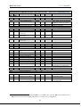
9 Emergency Objects
CANopen Emergency messages are triggered by the occurrence of an internal (fatal) error
situation. An Emergency CAN-message has the following general syntax:
BATCAN → Host
COB-ID
Byte 0-1
080h +
Emergency
Error Code
NodeID
Byte 2
Error Register
(Object 1001h)
Byte 3-7
Manufacturer specific error field
A toggle bit is present in byte 7 of the Emergency message. Byte 7 alternates between the
values 00h and 80h from one Emergency message to the next.
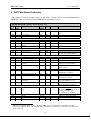
The following Emergency messages can be generated by the BATCAN application:
Error
Description
Emergency
Error Code
Manufacturer-specific Error Field
(byte 3-7)
(byte 1-0; hex)
CAN communication
8100
Byte 3: 00h
Byte 4: total format error count
Byte 5: error counter
Byte 6: bus-off counter (see OD index 3200, sub 3)
CAN buffer overrun
8110h
CAN message buffer in RAM full: at least 1 message was lost
Life Guarding time-out
8130
CAN-controller has been reinitialized
RPDO: too few bytes
8210
Byte 3: minimum DLC (Data Length Code)
CRC error
5000
Byte 3: 30h
Byte 4: 1 (program FLASH)
EEPROM: write error
5000
EEPROM: read error
5000
Byte 3: 41h
Byte 4: Parameter block index 1
Byte 5: 0 : writing block info
> 0: size of parameter block to write
Byte 3: 42h
Byte 4: Parameter block index 1
Byte 5: Error id (1=CRC, 2=length, 4=infoblock)
…table continues on the next page…
1
0: PDO communication parameters, 1: Guarding parameters, 2: ---, 3: ---, 4: B-sensor ADC configuration, 5: ---,
6: CAN configuration parameters, 7: ---, FFh: BATCAN Serial Number.
26
v1.3 5-Jul-2012
BATCAN module
Error
Description
Emergency
Error Code
Manufacturer-specific Error Field
(byte 3-7)
(byte 1-0; hex)
B-sensor ADC:
conversion timeout
5000
B-sensor ADC:
reset failed
5000
B-sensor ADC:
Hall-sensor calibration failed
B-sensor ADC:
T-sensor calibration failed
B-sensor ADC problem(s)
during initialisation
(check OD 1002)
5000
Irregular reset (Watchdog,
Brown-out or JTAG)
5000
Byte 3: F0h
Byte 4: microcontroller MCUSR register contents 2
Bootloader: not present
5000
Byte 3: F1h
Bootloader is now in control 3
5000
Bootloader cannot jump to
application: invalid 3
6000
Byte 3: FEh
Byte 4: 80h (81h in case of an AT90CAN128 micro)
Byte 5: 64h (28h for AT90CAN128, 32h for AT90CAN32)
Byte 6: microcontroller MCUSR register contents 2
Byte 3: FEh
Byte 4: AAh
Byte 5: AAh
5000
5000
Byte 3: 51h
Byte 4: B-sensor number (0)
Byte 5: ADC channel number (0..7)
Byte 3: 52h
Byte 4: B-sensor number (0)
Byte 5: Error id 1
Byte 3: 53h
Byte 4: B-sensor number (0)
Byte 3: 54h
Byte 4: B-sensor number (0)
Byte 3: 55h
Byte 4: ADC status (see OD index 1002)
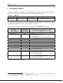
Byte 2 of the Emergency message contains the value of the socalled Error Register (Object
Dictionary index 1001h, a mandatory CANopen object). One or more bits of the 8-bit Error
Register can be set to 1, depending on the node's history of errors since the last reset. The table below gives a description of the different bits.
Error Register (Object 1001h) bits
Bit
0
1
2
3
4
5
6
7
1
2
3
Error type
generic
current
voltage
temperature
communication
device profile specific
reserved (=0)
manufacturer specific
01h: Reset-Valid bit not set, 02h: Reset-Valid bit not reset, 04h: error in initial Offset Register value,
08h: error in initial Gain Register value.
AT90CANxx MCUSR register bits: 01h: Power-On Reset, 02h: External Reset, 04h: Brown-Out Reset,
08h: Watchdog Reset, 10h: JTAG Reset.
This Emergency message is generated by the Bootloader program !
27
v1.3 5-Jul-2012
BATCAN module
References
[1] H.Boterenbrood
B-sensor Module, operation, readout and data-acquisition,
presentation at ATLAS Magnetic Field Workshop, 31 March 2005 (slightly outdated..).
http://www.nikhef.nl/pub/departments/ct/po/html/Bsensor/Bsensor-BfieldWS-31MAR05.pdf
[2] H.Boterenbrood,
MDT-DCS CANopen Module,
Version 2.7, NIKHEF, Amsterdam, 19 August 2011.
http://www.nikhef.nl/pub/departments/ct/po/html/MDT/MDT-DCS-CANnode.pdf
[3] F.Bergsma, H.Boterenbrood,
BsCAN3, a modular 3D B-field sensor system with CANopen read-out,
NIKHEF/CERN, Geneva, 13 May 2012.
http://www.nikhef.nl/pub/departments/ct/po/html/Bsensor/BsCAN3.pdf
[4] H.Boterenbrood,
mBATCAN, module for multiple B-sensor read-out by CAN bus and CANopen,
Version 1.1, NIKHEF/CERN, Geneva, 13 July 2012.
http://www.nikhef.nl/pub/departments/ct/po/html/Bsensor/mBATCAN.pdf
[5] H.Boterenbrood,
CANopen, high-level protocol for CAN-bus,
Version 3.0, NIKHEF, Amsterdam, 20 March 2000.
http://www.nikhef.nl/pub/departments/ct/po/doc/CANopen30.pdf
[6] CAN-in-Automation e.V.,
CANopen, Application Layer and Communication Profile,
CiA DS-301, Version 4.0, 16 June 1999.
[7] H.Boterenbrood,
CANopen Bootloader for the ELMB ATmega128 microcontroller,
Version 1.1, NIKHEF, Amsterdam, 10 March 2004.
http://www.nikhef.nl/pub/departments/ct/po/html/ELMB128/ELMBbl-doc.pdf
28
v1.3 5-Jul-2012
BATCAN module
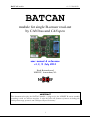
Appendix A. NTC Temperature Sensor Data
(datasheets taken from manufacturer website: http://www.thermometrics.com/)
29
v1.3 5-Jul-2012
BATCAN module
30