1
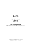
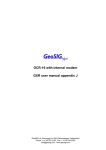
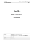
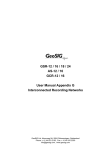
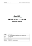
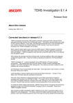
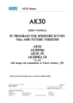
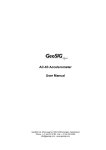
GS_GeoDAS_UserManual_Extension_V02.doc/18.09.2009
GeoDAS Manual
GeoDAS
Links to GeoSIG Instruments
User Manual Extension
Company:
GeoSIG Ltd
Author:
Oleg Razinkov
Checked:
Talhan Biro
Approved:
Johannes Grob
Distribution:
GeoSIG Ltd (1), Customer on request
Ahornweg 5A, 5504 Othmarsingen, Switzerland,
Tel: +41 44 810 21 50, Fax: +41 44 810 23 50, E-mail: [email protected]
GeoSIG Ltd
Page i
GS_GeoDAS_UserManual_Extension_V02.doc/18.09.2009
GeoDAS Manual
GeoSIG Ltd
Page ii
Document Revision
Version Date
04.11.2005
07.08.2008
Comment
First revision
Minor format adjustments and useful name
Disclaimer
GeoSIG Ltd reserves the right to change the information contained in this document without notice. While the
information contained herein is assumed to be accurate, GeoSIG Ltd assumes no responsibility for any
errors or omissions.
Copyright Notice
No part of this document may be reproduced without the prior written consent of GeoSIG Ltd. The software
described in this document is furnished under a license and may only be used or copied in accordance with
the terms of such a license.
Trademark
All brand and product names are trademarks or registered trademarks of their respective holders.
All rights reserved
GeoSIG Ltd
Switzerland
GS_GeoDAS_UserManual_Extension_V02.doc/18.09.2009
Software Documentation
GeoSIG Ltd.
Page 3 / 10
Table of Content
1
INTRODUCTION..........................................................................................................................................4
2
DIRECT LINK...............................................................................................................................................5
3
DIRECT LINK TO SEVERAL INSTRUMENTS ...........................................................................................6
4
DEDICATED DIAL-UP LINK .......................................................................................................................7
5
DIAL-UP LINK THROUGH THE SHARED MODEM...................................................................................8
6
DIAL-UP LINKS USING MODEM POOLS..................................................................................................9
7
DIAL-UP LINK TO SEVERAL INSTRUMENTS ..........................................................................................9
7
LINKS OVER VIRTUAL SERIAL CHANNELS .........................................................................................10
GeoSIG Ltd.
GS_GeoDAS_UserManual_Extension_V02.doc/18.09.2009
Software Documentation
1
Page 4 / 10
Introduction
This document describes the various links that can be established by the GeoDAS software and GeoSIG
recorders (GSR).
LINK 1
GSR 1
LINK 2
GSR 2
LINK 3
GSR 3
PC computer
GeoDAS
Stations list
Serial ports
GeoDAS maintains a stations list that is edited from the menu entry SETTINGS / CONFIGURE STATIONS
and supports various configurations of communication channels with instruments. The communication
parameters have to be defined for both sides of the link.
The parameters of these channels are specified in two configuration dialogs:
•
Communication Channel Setup sets communication parameters of GeoDAS for each configured
station
Communication tab of the Instrument Setup Manager (ISM) assigns the corresponding communication
settings to the instrument
•
The examples of most typical configurations are listed below and the corresponding communication
parameters are shown. They will be explained in the next sections.
-
Direct link
Direct link to several instruments
Dedicated Dial-up link
Dial-up link through the shared modem
Dial-up links using modem pools
Dial-up link to several instruments
GS_GeoDAS_UserManual_Extension_V02.doc/18.09.2009
Software Documentation
2
GeoSIG Ltd.
Page 5 / 10
Direct link
The instruments are located near to the computer running GeoDAS and are connected to it via serial RS-232
cables. This is the simplest and most common case.
COM1
RS-232
1st GSR
COM2
RS-232
2nd GSR
COMN
RS-232
Nth GSR
PC
Example of communication parameters for one link (assuming the cable is connected to the port COM1):
Important notes:
• GeoDAS supports up to 127 COM ports:
COM1 – COM127
GeoSIG Ltd.
GS_GeoDAS_UserManual_Extension_V02.doc/18.09.2009
Software Documentation
3
Page 6 / 10
Direct link to several instruments
Several GSR recording modules can be combined into the one multi-channel GNC unit or several
standalone recorders can form a synchronised network. In both cases more than one instrument are
accessed via same serial channel:
COM1
COM2
PC
COMN
1st GSR
RS-232
GNC-CR
Unit
2nd GSR
Nth GSR
In this case all recording modules should be configured with the same communication parameters as it is
illustrated with the example given in the section Direct link. You have to make sure that the work option
Login to single instrument is NOT enabled for all recording modules accessed through the same serial
channel.
Important notes:
• You cannot use Quick Login to the GNC modules through the “Add a Station” wizard, i.e. do not
select the option “I have the new instrument connected to a serial port of this computer”
• You have to add ALL recording modules of GNC to the configuration manually (Settings ->
Configure Stations -> Adding New Station…)
• You have to enter the correct serial number of the main board for each GNC recording module
being added manually
As a rule, the configuration file is supplied on the CD along with your GNC recorder. Therefore the simplest
way of configuration is to start “Add a Station” wizard, select the 2nd option and to locate a configuration file
provided with your instrument:
GeoSIG Ltd.
GS_GeoDAS_UserManual_Extension_V02.doc/18.09.2009
Software Documentation
4
Page 7 / 10
Dedicated Dial-up link
The instruments are accessed via dial-up link. Each link utilises its own analog modem connected to a
dedicated COM port of the computer
COM1
RS-232
Modem tel.123
Modem tel.321
Modem Cable
1st GSR
COM2
RS-232
Modem tel.124
Modem tel.322
Modem Cable
2nd GSR
COMN
RS-232
Modem tel.125
Modem tel.323
Modem Cable
Nth GSR
PC
Example of communication parameters for one link (upper link):
- an external modem is connected to the PC serial port COM1
- telephone number in the centre is 123, pulse dial
- telephone number at the place where instrument is located is 321
- instrument makes a call to the centre in case of an event
Important notes for dial-up links:
• Make sure that you have set the option
“Analog or GSM Modem” in the Instrument
tab of ISM
• Baud rates must be the set to the same fixed
value, 19200 baud is recommended for this
type of link
• The letter ‘P’ placed before the phone
number forces pulse dialling (supported by
almost all modems)
• S0=1 in the initialisation string makes the
remote modem answering automatically after
the 1st ring
• In order to set the proper initialisation string,
consult the user manual of your modem
• Timeout of the communication channel for
dial-up links should be set to at least 3000 –
5000 ms
Configuration procedure for the dial-up link (applied when the instrument is first configured):
• Connect to the instrument using direct link (cable), launch ISM and set communication parameters
required for the dial-up link
• After restart of the instrument configure GeoDAS for the dial-up link and connect once to the instrument
to make sure it is accessible
GeoSIG Ltd.
GS_GeoDAS_UserManual_Extension_V02.doc/18.09.2009
Software Documentation
5
Page 8 / 10
Dial-up link through the shared modem
Several instruments are accessed sequentially via dial-up links using the same modem connected to a COM
port of the computer
Modem tel.321
Modem Cable
1st GSR
COM2
Modem tel.322
Modem Cable
2nd GSR
COMN
Modem tel.323
Modem Cable
Nth GSR
COM1
PC
RS-232
Modem tel.123
Configuration A: the same as above, except the only modem is used for all links
Configuration B: using the modem pool with the only modem configured
Example of communication parameters for one link (upper link):
- an external modem is connected to the PC serial port COM1
- this modem is declared as a part of the modem pool TEST_Pool
- telephone number in the centre is 123, pulse dial
- telephone number at the place where instrument is located is 321
- instrument makes a call to the centre in case of an event
Configuration of the instrument is identical to the one shown above for the dedicated dial-up link.
The same notes and the configuration procedure described above are applicable.
GeoSIG Ltd.
GS_GeoDAS_UserManual_Extension_V02.doc/18.09.2009
Software Documentation
6
Page 9 / 10
Dial-up links using modem pools
Several instruments are accessed via dial-up links using several modems forming a modem pool.
COM1
RS-232
Modem tel.123
Modem tel.321
Modem Cable
1st GSR
COM2
RS-232
Modem tel.124
Modem tel.322
Modem Cable
2nd GSR
Modem tel.323
Modem Cable
Nth GSR
PC
Pool TEST_Pool
COMN
Modem pools may have (and in most cases they do) more than one modem as shown in the dialog below:
The pool consists of two modems and each of them can be used to connect to any of the remote instruments
configured in GeoDAS to be accessible through this modem pool. The modem for outgoing call is selected
from the list Ports assigned to the pool in the order as the ports are listed there. If a port is already used for
communication with a remote instrument, the next one is taken. If all ports are busy, GeoDAS waits for some
time until a port of the pool is released or until timeout is declared.
Unfortunately instruments cannot try to dial several numbers sequentially: callbacks from the instrument are
always made through the same modem of a pool. Therefore, configuring instrument settings, try to distribute
all telephone numbers of the pools evenly between all instruments or (better) assign the number of 1st
modem to fewer instruments because this modem is used more frequently for outgoing calls made by
GeoDAS.
7
Dial-up link to several instruments
This configuration is similar to the one described in the section Direct link to several instruments but the GNC
unit or several interconnected instruments are accessed through the dial-up link:
COM1
RS-232
Modem tel.123
Modem tel.321
COM2
PC
Modem Cable
COMN
GNC-CR
Unit
1st GSR
2nd GSR
Nth GSR
In this case one has to make sure also that all units are configured with their correct unique serial numbers
of the man boards. The above example is given for the dedicated dial-up link but the same would work also
through the shared modem or with a modem pool.
GeoSIG Ltd.
GS_GeoDAS_UserManual_Extension_V02.doc/18.09.2009
Software Documentation
7
Page 10 / 10
Links over virtual serial channels
This case is similar to the direct link, except that the COM ports are introduced to the operating system by
the drivers of corresponding TCP/IP to serial converters.
COM1
COM2
…..
COMN
PC
TCP/IP
TCP/IP - Serial
RS-232
1st GSR
TCP/IP - Serial
RS-232
2nd GSR
TCP/IP - Serial
RS-232
Nth GSR
Configuration parameters of such links are the same as those for direct channels, except the communication
timeout should be set to 3000 – 10000 ms, especially for the channels going through the slow TCP/IP links.
Note that initialisation of such channels at GeoDAS startup may take quite long.
Please refer to the GeoDAS manual (especially the sections 4.8 and 5.9) for more information about
communication channels and about their configuration.