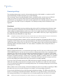
1
SymNet1
User Manual
Copyright
Copyright © 2007, GE Security, Inc. All rights reserved.
This document may not be copied in whole or in part or otherwise reproduced without prior
written consent from GE Security except where specifically permitted under US and
international copyright law.
Document number/revision: 0150-0332B (June 2007).
Disclaimer
The information in this document is subject to change without notice. GE Security, Inc.
(“GE Security”) assumes no responsibility for inaccuracies or omissions and specifically
disclaims any liabilities, losses, or risks, personal or otherwise, incurred as a consequence,
directly or indirectly, of the use or application of any of the contents of this document. For the
latest documentation, contact your local supplier or visit us online at www.gesecurity.com.
This publication may contain examples of screen captures and reports used in daily operations.
Examples may include fictitious names of individuals and companies. Any similarity to names
and addresses of actual businesses or persons is entirely coincidental.
Trademarks and patents
GE and the GE monogram are registered trademarks of General Electric Company.
SymNet1 product and logo are registered trademarks of GE Security.
Other trade names used in this document may be trademarks or registered trademarks of the
manufacturers or vendors of the respective products.
Software license agreement
Important: This end-user license agreement (“Agreement”) is a legal agreement between
GE SECURITY and You. Read the following terms and conditions carefully before installing or
using this Software. This agreement provides a license from GE SECURITY to use the Software.
It also contains warranty information, disclaimers, and liability limitations. Installing and/or
using the Software confirms Your agreement to be bound by these terms and conditions. If You
do not agree with these terms and conditions, do not install or use the Software or, if already
installed, immediately cease all use of the Software and promptly uninstall all components of
the Software.
1. Definitions. The following definitions apply to this document:
a. “GE SECURITY”, with respect to title to or warranty of the Software, means GE Security
Inc., a Delaware corporation.
b. “Software” means SymNav, the executable software or firmware programs and accompanying documentation installed on the GE SECURITY products, plus any upgrades,
modified versions, updates, additions, and copies of the software furnished to Customer
during the term of the license granted herein.
c. “Documentation” means all associated media, printed materials, and electronic documentation accompanying the Software.
d. “Licensed Product” means the Software and Documentation.
e. “Customer” means the person or organization, or parent or subsidiary thereof, who uses
the Software for its intended purposes, and excludes distributors, authorized resellers,
value-added resellers and original equipment manufacturers. Customer may be
referred to as You or Your, whether an individual or a business entity of any kind.
f. “Machine” means the computer, workstation, terminal, or other hardware product on
which the Software is installed.
2. License. All rights to and in the Licensed Product, including, but not limited to, copyrights,
patents, trademarks, and trade secrets, belong to GE SECURITY, and GE SECURITY retains title
to each copy of the Software. You agree that GE SECURITY at any time, upon reasonable
notice, may audit Your use of the Software for compliance with the terms and conditions of
this Agreement. Subject to the terms and conditions of this Agreement, GE SECURITY grants
You a nonexclusive license to use the Software, but only in the country where acquired,
provided that You agree to the following:
You may:
a. install and use the Software on a single Machine at one time, unless You have purchased
additional copies of the Software, in which case You may install the software on the
number of Machines for which You have purchased copies of the Software;
b. use the original copy of the Software provided to You for backup purposes.
iii
You may not:
a. transfer or distribute the Licensed Product to others, in electronic format or otherwise, and this
Agreement shall automatically terminate in the event of such a transfer or distribution;
b. use the Software over a computer network;
c. sell, rent, lease, or sublicense the Software;
d. copy or modify the Licensed Product for any purpose, including for backup purposes.
3. Term. This Agreement is effective until terminated. You may terminate this Agreement by
uninstalling all components of the Software from all Machines and returning the Software to
GE SECURITY. GE SECURITY may terminate this Agreement if You breach any of these terms
and conditions. Upon termination of this Agreement for any reason, You agree to uninstall
all components of the Software and return the Licensed Product to GE SECURITY. All
provisions of this Agreement relating to (i) disclaimer of warranties; (ii) limitations on liability,
remedies, and damages; and (iii) GE SECURITY’s proprietary rights, shall survive termination
of this Agreement.
4. Object code. The Software is delivered in object code only. You may not alter, merge,
modify, adapt, or translate the Software, nor decompile, disassemble, reverse-engineer, or
otherwise reduce the Software to a human-perceivable form, nor create derivative works or
programs based on the Software.
5. Limited warranty. GE SECURITY warrants that for one (1) year from the date of delivery of
the Licensed Product (Software Warranty Period), the functions contained in the Software will
be fit for their intended purpose as described in the applicable Documentation from
GE SECURITY, and will conform in all material respects to the specifications stated in such
Documentation. GE SECURITY does not warrant that the operation of the Software will be
uninterrupted or error-free. GE SECURITY does warrant that the media on which the
Software is furnished will be free from defects in materials and workmanship under normal
use for a period of thirty (30) days from the date of delivery (Media Warranty Period). Except
as specifically provided therein, any other software and any hardware furnished with or
accompanying the Software is not warranted by GE SECURITY.
Your exclusive remedy under this limited warranty for nonconforming Software shall be
repair or replacement of the Software, at the sole discretion of GE SECURITY. To obtain a
repair or replacement of nonconforming Software, contact GE SECURITY Customer Service
toll-free at 888-GESECURity or online at www.gesecurity.com during the Software Warranty
Period.
Except as expressly provided above, the licensed product is provided “as is” without
warranty of any kind, either expressed or implied, including, but not limited to, implied
warranties of merchantability or fitness for a particular purpose and, except as expressly
provided above, You assume the entire risk as to the quality and performance of the licensed
product.
6. Limitation of liability. GE SECURITY’s sole obligation or liability under this agreement is the
repair or replacement of nonconforming software and/or defective media according to the
limited warranty above. In no event will GE SECURITY be liable for damages, whether
consequential, incidental, or indirect, nor for loss of data, loss of profits, or lost savings,
arising from use or inability to use the software or documentation (or any hardware
furnished with the software), even if GE SECURITY has been advised of the possibility of such
damages, nor for any claim by any third party.
7. General. Any materials provided to You by GE SECURITY shall not be exported or
reexported in violation of any export provisions of the USA or any other applicable
jurisdiction. Any attempt to sublicense, assign, or transfer any of the rights, duties, or
obligations hereunder shall be void. This Agreement shall be governed by and interpreted
under the laws of the State of New York, United States of America, without regard to conflicts
of law provisions. You hereby consent to the exclusive jurisdiction of the state and federal
courts located in Multnomah County, Oregon, to resolve any disputes arising under or in
connection with this Agreement, with venue in Portland, Oregon.
iv
SymNet1
User Manual
8. Restricted rights legend. The Licensed Product is provided with RESTRICTED RIGHTS. In
the event the United States Government or an agency thereof is granted a license, the
following additional terms apply: Restricted Computer Software, as defined in the
Commercial Computer Software–Restricted Rights clause at Federal Acquisition Regulations
52.227-19, and the restrictions as provided in subparagraphs (c)(1) and (c)(2) thereof; and as
applicable, the Government’s rights to use, modify, reproduce, release, perform, display, or
disclose the Software also are restricted as provided by paragraphs (b)(2) and (b)(3) of the
Rights in Noncommercial Technical Data and Computer Software–Small Business Innovative
Research (SBIR) Program clause at DFARS 252.227-7018.
9. Acknowledgment. You acknowledge that You have read and understand this agreement
and agree to be bound by its terms. You further agree that this agreement is the complete
and exclusive statement of the agreement between You and GE SECURITY, and supersedes
any proposal or prior agreement, oral or written, and any other communication relating to
the subject matter of this agreement.
Intended use
Use this product only for the purpose it was designed for; refer to the data sheet and user
documentation. For the latest product information, contact your local supplier or visit us online
at www.gesecurity.com.
FCC compliance
This equipment has been tested and found to comply with the limits for a Class A digital device,
pursuant to part 15 of the FCC Rules. These limits are designed to provide reasonable
protection against harmful interference when the equipment is operated in a commercial
environment. This equipment generates, uses, and can radiate radio frequency energy and, if
not installed and used in accordance with the instruction manual, may cause harmful
interference to radio communications.
You are cautioned that any changes or modifications not expressly approved by the party
responsible for compliance could void the user’s authority to operate the equipment.
Regulatory
v
Contents
Preface . . . . . . . . . . . . . . . . . . . . . . . . . . . . . . . . . . . . . . . . . . . . . . . . . . . . . . . . . . . . . . . . . . . . . . . . . . . . . . . . . . . . . . . . vii
Conventions used in this document . . . . . . . . . . . . . . . . . . . . . . . . . . . . . . . . . . . . . . . . . . . . . . . . . . . . . . . . . . . . . . . . . .vii
Safety terms and symbols . . . . . . . . . . . . . . . . . . . . . . . . . . . . . . . . . . . . . . . . . . . . . . . . . . . . . . . . . . . . . . . . . . . . . . . . . . .vii
Chapter 1.
Overview. . . . . . . . . . . . . . . . . . . . . . . . . . . . . . . . . . . . . . . . . . . . . . . . . . . . . . . . . . . . . . . 1
Product description. . . . . . . . . . . . . . . . . . . . . . . . . . . . . . . . . . . . . . . . . . . . . . . . . . . . . . . . . . . . . . . . . . . . . . . . . . . . . . 2
Features. . . . . . . . . . . . . . . . . . . . . . . . . . . . . . . . . . . . . . . . . . . . . . . . . . . . . . . . . . . . . . . . . . . . . . . . . . . . . . . . . . . . . . . . . . . . .2
Product contents . . . . . . . . . . . . . . . . . . . . . . . . . . . . . . . . . . . . . . . . . . . . . . . . . . . . . . . . . . . . . . . . . . . . . . . . . . . . . . . . . . . .3
Installation environment . . . . . . . . . . . . . . . . . . . . . . . . . . . . . . . . . . . . . . . . . . . . . . . . . . . . . . . . . . . . . . . . . . . . . . . . . . . . .4
Associated equipment . . . . . . . . . . . . . . . . . . . . . . . . . . . . . . . . . . . . . . . . . . . . . . . . . . . . . . . . . . . . . . . . . . . . . . . . . . . . . . .4
Passwords. . . . . . . . . . . . . . . . . . . . . . . . . . . . . . . . . . . . . . . . . . . . . . . . . . . . . . . . . . . . . . . . . . . . . . . . . . . . . . . . . . . . . . . . . . .5
Default IP addresses . . . . . . . . . . . . . . . . . . . . . . . . . . . . . . . . . . . . . . . . . . . . . . . . . . . . . . . . . . . . . . . . . . . . . . . . . . . . . . . . .5
SymNet1 connectors and indicators . . . . . . . . . . . . . . . . . . . . . . . . . . . . . . . . . . . . . . . . . . . . . . . . . . . . . . . . . . . . . . . 6
Connectors . . . . . . . . . . . . . . . . . . . . . . . . . . . . . . . . . . . . . . . . . . . . . . . . . . . . . . . . . . . . . . . . . . . . . . . . . . . . . . . . . . . . . . . . . .6
Indicators . . . . . . . . . . . . . . . . . . . . . . . . . . . . . . . . . . . . . . . . . . . . . . . . . . . . . . . . . . . . . . . . . . . . . . . . . . . . . . . . . . . . . . . . . . .6
Chapter 2.
Installation . . . . . . . . . . . . . . . . . . . . . . . . . . . . . . . . . . . . . . . . . . . . . . . . . . . . . . . . . . . . . 7
Power connections . . . . . . . . . . . . . . . . . . . . . . . . . . . . . . . . . . . . . . . . . . . . . . . . . . . . . . . . . . . . . . . . . . . . . . . . . . . . . . 8
IP address setting . . . . . . . . . . . . . . . . . . . . . . . . . . . . . . . . . . . . . . . . . . . . . . . . . . . . . . . . . . . . . . . . . . . . . . . . . . . . . . . 9
Serial cable . . . . . . . . . . . . . . . . . . . . . . . . . . . . . . . . . . . . . . . . . . . . . . . . . . . . . . . . . . . . . . . . . . . . . . . . . . . . . . . . . . . . . . . . . .9
HyperTerminal . . . . . . . . . . . . . . . . . . . . . . . . . . . . . . . . . . . . . . . . . . . . . . . . . . . . . . . . . . . . . . . . . . . . . . . . . . . . . . . . . . . . . 10
General connections . . . . . . . . . . . . . . . . . . . . . . . . . . . . . . . . . . . . . . . . . . . . . . . . . . . . . . . . . . . . . . . . . . . . . . . . . . . . 11
Audio and alarm connections . . . . . . . . . . . . . . . . . . . . . . . . . . . . . . . . . . . . . . . . . . . . . . . . . . . . . . . . . . . . . . . . . . . . 12
RS-485 solution wiring . . . . . . . . . . . . . . . . . . . . . . . . . . . . . . . . . . . . . . . . . . . . . . . . . . . . . . . . . . . . . . . . . . . . . . . . . . 12
Chapter 3.
WebServer . . . . . . . . . . . . . . . . . . . . . . . . . . . . . . . . . . . . . . . . . . . . . . . . . . . . . . . . . . . . 13
WebServer overview . . . . . . . . . . . . . . . . . . . . . . . . . . . . . . . . . . . . . . . . . . . . . . . . . . . . . . . . . . . . . . . . . . . . . . . . . . . . 14
SymBrowser page . . . . . . . . . . . . . . . . . . . . . . . . . . . . . . . . . . . . . . . . . . . . . . . . . . . . . . . . . . . . . . . . . . . . . . . . . . . . . . 15
Configuration page . . . . . . . . . . . . . . . . . . . . . . . . . . . . . . . . . . . . . . . . . . . . . . . . . . . . . . . . . . . . . . . . . . . . . . . . . . . . . 16
Network settings. . . . . . . . . . . . . . . . . . . . . . . . . . . . . . . . . . . . . . . . . . . . . . . . . . . . . . . . . . . . . . . . . . . . . . . . . . . . . . . . . . . 17
Streaming settings . . . . . . . . . . . . . . . . . . . . . . . . . . . . . . . . . . . . . . . . . . . . . . . . . . . . . . . . . . . . . . . . . . . . . . . . . . . . . . . . . 18
Camera settings . . . . . . . . . . . . . . . . . . . . . . . . . . . . . . . . . . . . . . . . . . . . . . . . . . . . . . . . . . . . . . . . . . . . . . . . . . . . . . . . . . . 23
Serial pass through settings . . . . . . . . . . . . . . . . . . . . . . . . . . . . . . . . . . . . . . . . . . . . . . . . . . . . . . . . . . . . . . . . . . . . . . . . 27
Alarm Setup . . . . . . . . . . . . . . . . . . . . . . . . . . . . . . . . . . . . . . . . . . . . . . . . . . . . . . . . . . . . . . . . . . . . . . . . . . . . . . . . . . . . . . . 30
Display options . . . . . . . . . . . . . . . . . . . . . . . . . . . . . . . . . . . . . . . . . . . . . . . . . . . . . . . . . . . . . . . . . . . . . . . . . . . . . . . . . . . . 31
Password settings . . . . . . . . . . . . . . . . . . . . . . . . . . . . . . . . . . . . . . . . . . . . . . . . . . . . . . . . . . . . . . . . . . . . . . . . . . . . . . . . . 31
Network time protocol settings . . . . . . . . . . . . . . . . . . . . . . . . . . . . . . . . . . . . . . . . . . . . . . . . . . . . . . . . . . . . . . . . . . . . . 32
Factory reset . . . . . . . . . . . . . . . . . . . . . . . . . . . . . . . . . . . . . . . . . . . . . . . . . . . . . . . . . . . . . . . . . . . . . . . . . . . . . . . . . . . . . . 32
Info page . . . . . . . . . . . . . . . . . . . . . . . . . . . . . . . . . . . . . . . . . . . . . . . . . . . . . . . . . . . . . . . . . . . . . . . . . . . . . . . . . . . . . . 33
Chapter 4.
Upgrading . . . . . . . . . . . . . . . . . . . . . . . . . . . . . . . . . . . . . . . . . . . . . . . . . . . . . . . . . . . . 35
Upgrade page . . . . . . . . . . . . . . . . . . . . . . . . . . . . . . . . . . . . . . . . . . . . . . . . . . . . . . . . . . . . . . . . . . . . . . . . . . . . . . . . . . 36
Flash recovery system . . . . . . . . . . . . . . . . . . . . . . . . . . . . . . . . . . . . . . . . . . . . . . . . . . . . . . . . . . . . . . . . . . . . . . . . . . 38
Flash recovery over the Ethernet. . . . . . . . . . . . . . . . . . . . . . . . . . . . . . . . . . . . . . . . . . . . . . . . . . . . . . . . . . . . . . . . . . . . 38
Flash recovery over RS-232. . . . . . . . . . . . . . . . . . . . . . . . . . . . . . . . . . . . . . . . . . . . . . . . . . . . . . . . . . . . . . . . . . . . . . . . . 39
vi
SymNet1
User Manual
Chapter 5.
Technical specifications . . . . . . . . . . . . . . . . . . . . . . . . . . . . . . . . . . . . . . . . . . . . . . . . 41
Technical specifications. . . . . . . . . . . . . . . . . . . . . . . . . . . . . . . . . . . . . . . . . . . . . . . . . . . . . . . . . . . . . . . . . . . . . . . . . 42
General . . . . . . . . . . . . . . . . . . . . . . . . . . . . . . . . . . . . . . . . . . . . . . . . . . . . . . . . . . . . . . . . . . . . . . . . . . . . . . . . . . . . . . . . . . . . 42
Connections . . . . . . . . . . . . . . . . . . . . . . . . . . . . . . . . . . . . . . . . . . . . . . . . . . . . . . . . . . . . . . . . . . . . . . . . . . . . . . . . . . . . . . . 42
Video . . . . . . . . . . . . . . . . . . . . . . . . . . . . . . . . . . . . . . . . . . . . . . . . . . . . . . . . . . . . . . . . . . . . . . . . . . . . . . . . . . . . . . . . . . . . . . 42
Audio . . . . . . . . . . . . . . . . . . . . . . . . . . . . . . . . . . . . . . . . . . . . . . . . . . . . . . . . . . . . . . . . . . . . . . . . . . . . . . . . . . . . . . . . . . . . . . 42
Part numbers . . . . . . . . . . . . . . . . . . . . . . . . . . . . . . . . . . . . . . . . . . . . . . . . . . . . . . . . . . . . . . . . . . . . . . . . . . . . . . . . . . . . . . 42
Chapter 6.
Technical support. . . . . . . . . . . . . . . . . . . . . . . . . . . . . . . . . . . . . . . . . . . . . . . . . . . . . . 43
Contacting technical support. . . . . . . . . . . . . . . . . . . . . . . . . . . . . . . . . . . . . . . . . . . . . . . . . . . . . . . . . . . . . . . . . . . . 44
Online publication library . . . . . . . . . . . . . . . . . . . . . . . . . . . . . . . . . . . . . . . . . . . . . . . . . . . . . . . . . . . . . . . . . . . . . . . . . . . 44
vii
Preface
This is the GE SymNet1 User Manual for model SymNet1-5RC. This document includes an overview of the
product and detailed instructions explaining:
•
•
how to install and configure; and
how to connect to other GE IP devices.
There is also information describing how to contact technical support if you have questions or concerns.
To use this document effectively, you should have the following minimum qualifications:
•
•
a basic knowledge of CCTV systems and components; and
a basic knowledge of electrical wiring and low-voltage electrical connections.
Read these instructions and all ancillary documentation entirely before installing or operating this product.
The most current versions of this and related documentation may be found on our website. Refer to Online
publication library on page 44 for instructions on accessing our online publication library.
Note:
A qualified service person, complying with all applicable codes, should perform all required hardware installation.
Conventions used in this document
The following conventions are used in this document:
Bold
Menu items and buttons.
Italic
Emphasis of an instruction or point; special terms.
File names, path names, windows, panes, tabs, fields, variables, and other GUI elements.
Titles of books and various documents.
Blue italic
(Electronic version.) Hyperlinks to cross-references, related topics, and URL addresses.
Monospace
Text that displays on the computer screen.
Programming or coding sequences.
Safety terms and symbols
These terms may appear in this manual:
CAUTION:
Cautions identify conditions or practices that may result in damage to the equipment or other property.
WARNING:
Warnings identify conditions or practices that could result in equipment damage or serious personal injury.
viii
SymNet1
User Manual
Chapter 1 Overview
This chapter provides an overview of your SymNet1, including features, product
contents, installation environment, and default IP addresses.
In this chapter:
Product description. . . . . . . . . . . . . . . . . . . . . . . . . . . . . . . . . . . . . . . . . . 2
Features . . . . . . . . . . . . . . . . . . . . . . . . . . . . . . . . . . . . . . . . . . . . . . . 2
Product contents. . . . . . . . . . . . . . . . . . . . . . . . . . . . . . . . . . . . . . . . . 3
Installation environment. . . . . . . . . . . . . . . . . . . . . . . . . . . . . . . . . . . 4
Associated equipment. . . . . . . . . . . . . . . . . . . . . . . . . . . . . . . . . . . . . 4
Passwords. . . . . . . . . . . . . . . . . . . . . . . . . . . . . . . . . . . . . . . . . . . . . . 5
Default IP addresses . . . . . . . . . . . . . . . . . . . . . . . . . . . . . . . . . . . . . 5
SymNet1 connectors and indicators . . . . . . . . . . . . . . . . . . . . . . . . . . . . . 6
Connectors . . . . . . . . . . . . . . . . . . . . . . . . . . . . . . . . . . . . . . . . . . . . . 6
Indicators . . . . . . . . . . . . . . . . . . . . . . . . . . . . . . . . . . . . . . . . . . . . . . 6
2
SymNet1
User Manual
Product description
The GE SymNet1-5RC is a small footprint video streaming unit that is used for video monitoring and
surveillance over IP networks. It uses MPEG-4 compression technologies to deliver high quality video, audio,
and data over 10/100 Base-T networks. The SymNet1’s basic function is to either encode analog video (NTSC)
to MPEG-4 digital video or decode MPEG-4 digital video to analog video. The SymNet1-5RC is a standalone
unit that can be horizontally or vertically mounted.
Features
SynNet1-5RC features include:
•
•
•
•
•
•
•
•
•
•
Compatibility with SymNet1, SymDec-16, SymVeo SV-XP1 IP camera, and SymNav software.
Advanced MPEG4 video compression.
Composite video input and output connection.
Alarm input and output connections.
Remote configuration over ethernet or RS-232 serial cable.
Password protection.
Standard, medium, and high video quality settings.
Encoder or decoder capability.
Video streaming with UDP and TCP/IP support.
Flash recovery feature.
Chapter 1
Overview
Product contents
The SymNet1 system consists of the following:
•
•
•
•
•
•
•
SymNet1
SymNet1 User Manual
SymNav software CD
12 VDC 1.33 amp power supply
20-way 2-row terminal block connector
three-position connector
RS-232 serial cable
Check the package and contents (Figure 1) for visible damage. If any components are missing or damaged,
contact the supplier immediately. Do not attempt to use the unit. If, for any reason they must be returned, the
contents must be shipped in the original packaging.
Figure 1. SymNet1 product contents
SymNet1
20-way
I/O terminal
RS-232 serial cable
and ferrite sleeve
Manual
Three-position
terminal
Power supply
SymNav
software CD
3
4
SymNet1
User Manual
Installation environment
You should consider the following environmental elements when installing the SymNet1:
Power: Ensure that the site's AC power is stable and within the rated voltage of the external power
supply. If the site's AC power is likely to have spikes or power dips, use power line conditioning or
an uninterruptible power supply (UPS).
Ventilation: Install the unit in a well-ventilated area. Take note of the locations of the cooling vents in
the unit's enclosure, and ensure that they are not obstructed.
Temperature: Observe the unit's ambient temperature specifications when choosing a location space.
Extremes of heat or cold beyond the specified operating temperature limits may cause the unit to
fail. Do not install the unit on top of other hot equipment.
Moisture: Do not expose the unit to rain or moisture. Moisture can damage the internal components.
Do not install this unit near sources of water.
Associated equipment
You may need the following associated equipment:
•
•
•
•
•
•
SymVeo SV-XP1 IP camera.
Analog monitor to view video.
Alarm input devices such as pressure sensors and motion detectors.
Alarm output devices such as buzzers, sirens, and flashing lights.
PC connected via an ethernet cable.
Slotted screwdriver with a tip size of 2 cm or smaller.
For instructions regarding the connection of the associated security equipment in your system, please consult
the instruction manual of the associated equipment.
Chapter 1
Overview
Passwords
Passwords are provided to limit access to the WebServer and the SymNav software. We recommend that you
change the default passwords (Table 1) after you complete the installation. As a security measure, store the
passwords in the administrator's secured files or in a limited access area.
Table 1.
Default passwords
Password name
Program
Changeable by user
Default password
Admin password
WebServer
Yes, through the webserver.
admin
Log In password
SymNav
Yes, through the Security
menu.
12345
Default IP addresses
The SymNet1 comes with the following preset IP addresses:
•
•
•
Note:
IP address of 192.168.1.12
Subnet mask of 255.255.255.0
Gateway address of 192.168.1.1
These IP addresses should be changed before you connect to your IP network. Contact your network administrator to
obtain your network specific addresses.
5
6
SymNet1
User Manual
SymNet1 connectors and indicators
Figure 2 shows the SymNet1 connectors and indicators.
Figure 2. Connectors and indicators
Power LED
Line LED
TX LED RX LED
Ethernet port
Reset button
Power connector
I/O port
Video in/out ports
Connectors
SymNet1 connectors include:
Power connector. Connects the external power supply to the SymNet1-5RC.
I/O connector. Connects alarm, audio, RS-232, RS-485 input and output.
Video I/O connector. Input and output connection of two composite video signals through two separated
BNC connectors.
Ethernet port. Connects to a LAN or WAN. Used for upgrading the software over the Internet and
accessing the webserver.
Reset button. Resets the SymNet1.
Indicators
SymNet1 indicators include:
Power LED. Indicates power is on when LED is lit.
Line LED. Indicates data activity on the ethernet port.
TX LED. Indicates the unit is transmitting data.
RX LED. Indicates the unit is receiving data.
Chapter 2 Installation
This chapter provides information on installing your SymNet1, including wiring
connections and instructions on setting the IP address.
In this chapter:
Power connections . . . . . . . . . . . . . . . . . . . . . . . . . . . . . . . . . . . . . . . . . . 8
IP address setting . . . . . . . . . . . . . . . . . . . . . . . . . . . . . . . . . . . . . . . . . . . 9
General connections . . . . . . . . . . . . . . . . . . . . . . . . . . . . . . . . . . . . . . . . 11
Audio and alarm connections . . . . . . . . . . . . . . . . . . . . . . . . . . . . . . . . . 12
RS-485 solution wiring . . . . . . . . . . . . . . . . . . . . . . . . . . . . . . . . . . . . . . 12
8
SymNet1
User Manual
Power connections
To make the power connections, see Figure 3 and do the following:
1. Use a screwdriver to loosen the terminal screws (pins 1 and 3) on the provided three-position terminal
block.
2. Insert the flying leads into sockets 1 and 3. The +12V lead at pin 3 and the ground lead at pin 1.
3. Retighten the terminal screws until snug, ensuring that the power leads are secure.
4. Insert the terminal block into the power connector of the SymNet1.
5. Supply power to the unit by plugging the power supply into a properly rated power source.
The power LED illuminates to show that the SymNet1 is receiving power. If it does not illuminate, check the
terminal block connections and the power source.
Figure 3. The terminal block connections
Pin 1
Pin 3
Chapter 2
Installation
IP address setting
In order to use the SymNet1 correctly you must change the IP addresses from the defaults to ones that your
specific network will recognize. This requires a serial cable (provided) and a connection to a PC.
Serial cable
To make a serial connection, see Figure 4 and Figure 5 and do the following:
1. Orient the 20-way terminal connector with the 20-way socket side down and the keying ridge facing
away.
Note:
If the serial cable is already connected to the terminal connector go directly to step 4.
2. Insert a small slotted screwdriver into pin 15 on the 3rd row down. Push the screwdriver until it
bottoms out. Insert the blue/white wire into pin 15.
3. Repeat step 2 with the blue wire in pin 16 and the orange/white wire in pin 20.
4. Clip the ferrite sleeve (provided) on to the serial cable.
5. Insert the connector into the I/O socket on the SymNet1 and insert the DB9-M end into the serial port
(COM1) of your PC.
Figure 4. Serial cable schematic
DB9-M
20-way terminal
connector
Figure 5. 20-way terminal block wiring for RS232 protocol
1
2
3
4
5
6
7
8
9
10
Keying ridge
Insert screwdriver
in this row
15 16
20
9
10
SymNet1
User Manual
HyperTerminal
To run HyperTerminal, do the following:
1. Power up the SymNet1.
2. Launch HyperTerminal by selecting Start > Programs > Accessories > Communications >
HyperTerminal.
3. Type in <any name> in the Connection description dialog box and click OK.
4. Select the correct COM port and click OK.
5. Ensure the port settings are 57600 baud, 8 data bits, 1 stop bit, no parity, and no flow control. Click
OK.
6. Enter ? to display the menu.
7. Press 1 for the network settings.
8. Press 2 to change the network settings.
9. Type n to disable DHCP and then press Enter.
10. Enter the new IP addresses and then press Enter.
Note:
Obtain your network specific IP addresses from your network administrator.
11. After the Gateway address is entered the SymNet1 will reboot.
12. Remove power from the SymNet1 and disconnect the serial cable from your PC.
Chapter 2
Installation
General connections
Use Figure 6 as a guide to connect the various peripherals to the connections on the SymNet1.
Figure 6. Connection diagram
Speaker with amp
(line-level audio out)
Alarm I/O
and RS-484
PC with SymNav
RS-232
Line-level microphone with amp
(audio in)
Out
In
Power supply
Composite video in and video out
11
12
SymNet1
User Manual
Audio and alarm connections
To add alarm, audio, and RS-485 connections, wire the 20-way terminal block as shown in Figure 7.
Figure 7. I/O Port pin numbering
1
2
3
4
5
6
7
8
9
10
11 12 13 14 15 16 17 18 19 20
The side of the SymNet1 is equipped with an accessories I/O Port (20-pin connector). Wire all I/O devices to
the 20-way terminal connector that was supplied with the unit. Connect the terminal connector to the I/O port.
Do not attempt to wire accessories directly to the I/O port. If the terminal connector is lost or missing, contact
GE Customer Service for a replacement.
Table 2 describes the 20-way terminal connector.
Table 2.
20-way terminal connector
Pin number
Description
Pin number
Description
Pin 1
Ground
Pin 11
RS-422/485 TX+
Pin 2
Alarm in
Pin 12
RS-422/485 TX-
Pin 3
Ground
Pin 13
RS-422/485 RX+
Pin 4
Alarm out
Pin 14
RS-422/485 RX-
Pin 5
Ground
Pin 15
RS-232 TXD
Pin 6
Audio in
Pin 16
RS-232 RXD
Pin 7
Ground
Pin 17
RTS
Pin 8
Audio out
Pin 18
CTS
Pin 9
Ground
Pin 19
DCD
Pin 10
Ground
PIn 20
RS-232 ground
RS-485 solution wiring
To set up a two-wire bidirectional RS-485 connection to control a DVMRe or a KTD-405, do the following:
1. Connect a wire from pin 11 (TX+) to pin 13 (RX+) on the 20-pin terminal block.
2. Connect a wire from pin 12 (TX-) to pin 14 (RX-) on the 20-pin terminal block.
3. Connect a wire from the RS-485+ pin on the DVMRe or KTD-405 to pin 11 or 13 on the SymNet1
terminal block.
4. Connect a wire from the RS-485- pin on the DVMRe or KTD-405 to pin 12 or 14 on the SymNet1
terminal block.
Chapter 3 WebServer
This chapter provides an overview of the SymNet1 WebServer and instructions on
changing WebServer settings and options.
In this chapter:
WebServer overview . . . . . . . . . . . . . . . . . . . . . . . . . . . . . . . . . . . . . . . . 14
SymBrowser page . . . . . . . . . . . . . . . . . . . . . . . . . . . . . . . . . . . . . . . . . . 15
Configuration page . . . . . . . . . . . . . . . . . . . . . . . . . . . . . . . . . . . . . . . . . 16
Network settings . . . . . . . . . . . . . . . . . . . . . . . . . . . . . . . . . . . . . . . . 17
Streaming settings . . . . . . . . . . . . . . . . . . . . . . . . . . . . . . . . . . . . . . 18
Camera settings . . . . . . . . . . . . . . . . . . . . . . . . . . . . . . . . . . . . . . . . 23
Serial pass through settings . . . . . . . . . . . . . . . . . . . . . . . . . . . . . . . 27
Alarm Setup . . . . . . . . . . . . . . . . . . . . . . . . . . . . . . . . . . . . . . . . . . . 30
Display options. . . . . . . . . . . . . . . . . . . . . . . . . . . . . . . . . . . . . . . . . 31
Password settings . . . . . . . . . . . . . . . . . . . . . . . . . . . . . . . . . . . . . . . 31
Network time protocol settings. . . . . . . . . . . . . . . . . . . . . . . . . . . . . 32
Factory reset. . . . . . . . . . . . . . . . . . . . . . . . . . . . . . . . . . . . . . . . . . . 32
Info page . . . . . . . . . . . . . . . . . . . . . . . . . . . . . . . . . . . . . . . . . . . . . . . . . 33
14
SymNet1
User Manual
WebServer overview
The SymNet1 has an integrated WebServer interface. The WebServer provides the user the means to remotely
configure, upgrade, and view information about the SymNet1. The default IP address from the factory is
192.138.1.12. To get the SymNet1 to stream video, at a minimum the Streaming settings must be configured.
To access the web interface, do the following:
1. Launch Internet Explorer (version 5.5 or later) on any local Internet connected PC or laptop.
2. Type in the unit’s IP address (xxx.xxx.xxx.xxx) or hostname (see network settings page) in the address
field and press Enter. The Enter network password box displays.
3. Enter the correct username and password in their respective fields (the default username and password
is admin). Click OK.
4. The SymNet1 Home page appears (Figure 8).
Figure 8. SymNet1 home page
The Home page provides the following links:
•
•
•
•
SymBrowser (see SymBrowser page on page 15)
Configure (see Configuration page on page 16)
Info (see Info page on page 33)
Upgrade (see Upgrade page on page 36)
Chapter 3
WebServer
SymBrowser page
Click the SymBrowser link to launch the SymBrowser page (Figure 9). The SymBrowser page provides access
to live and recorded video without the need for additional software. Simply type in the unit’s IP address and
click the Connect button. The following features are available:
•
•
•
Right-click on the video to switch from live or playback mode or view full-screen.
Double-click to switch from a quad stream to a nonquad stream and back again.
In playback mode, use the Go to button to start playback from a selected time and date.
Figure 9. SymBrowser page
15
16
SymNet1
User Manual
Configuration page
Click the Configure link to launch the Configuration page (Figure 10).
Figure 10. Configuration page
The Configuration page allows you to remotely modify the following settings of the SymNet1:
•
•
•
•
•
•
•
•
Network settings (see Network settings on page 17)
Streaming settings (see Streaming settings on page 18)
Camera settings (see Camera settings on page 23)
Serial settings (see 2 Field Rates equals 1 Frame. on page 25)
Alarm setup (see Alarm Setup on page 30)
Password settings (see Password settings on page 31).
Network time protocol settings (see Network time protocol settings on page 32)
Factory reset (see Factory reset on page 32)
Chapter 3
WebServer
Network settings
The Network settings page (Figure 11) provides an alternate method of changing the SymNet1’s IP addresses.
You can also enable dynamic host configuration protocol (DHCP) and assign your unit a hostname. DHCP is
an Internet protocol for automating the configuration of devices that use TCP/IP. You can use DHCP to
automatically assign IP addresses.
Figure 11. Network settings
17
18
SymNet1
User Manual
Streaming settings
The streaming settings pages set up the video streaming properties of the SymNet1. A certain level of IP
network knowledge is required to properly set up video streaming.
Video streaming is the process that the SymDec family, including SymNet1 and the Symveo SV-XP1 IP
camera use to listen on a specific UDP/TCP port for control messages and respond to them. The
communication over this protocol can be between a PC application, such as SymNav software and any of the
above products. The UDP/TCP port is configurable. The default port setting is 8092. IP Multicast is also
supported.
IP multicast
IP multicast is a bandwidth-conserving technology that reduces traffic by simultaneously delivering a single
stream of information to thousands of recipients. IP Multicast delivers source traffic to multiple receivers
without adding any additional burden on the source or the receivers while using the least network bandwidth of
any competing technology. High-bandwidth applications, such as MPEG video, may require a large portion of
the available network bandwidth for a single stream.
Note:
Configured incorrectly IP multicast can become a serious drain on your networks resources! If you are at all uncertain
on how to setup IP multicast, please contact your network administrator or IS professional.
The Internet Assigned Numbers Authority (IANA) controls the assignment of IP multicast addresses. It has
assigned the Class D address space to be used for IP multicast. This means that all IP multicast group addresses
will fall in the range of 224.0.0.0 to 239.255.255.255. This address range is only used for the group address or
destination address of IP multicast traffic. The source address for multicast video is always the source or
senders IP address.
UDP sender and UDP receiver
UDP (User Datagram Protocol), is a connectionless protocol that, like TCP, runs on top of IP networks. Unlike
TCP/IP, UDP/IP provides very few error recovery services, offering instead a direct way to send and receive
datagrams over an IP network. It's used primarily for broadcasting messages over a network. A UDP sender
sends out digital video over an IP network. A UDP sender can be the SymDec-1, SymDec-4, Symveo SV-XP1
IP Camera, or SymNet1 (Encoder). A UDP receiver is typically a SymDec-1, SymNav software, or a SymDec4, which can display and record the streamed video. The SymNet1 (Decoder) can also be setup as a receiver,
but it can only display the streamed video since it does not have recording capability.
To prevent a waste of network resources, the UDP sender does not send out streaming video until a receiver
informs the sender that it is interested in receiving the stream. The UDP receiver sends out a Start message
every 30 seconds to the IP address in its streaming settings menu. The streaming settings page is located on the
receiving device's web page.
When a sender receives a Start message, it will start streaming out to the receivers that are requesting it. When
the sender does not receive any Start message for one minute, it will stop sending to that device.
To speed up the initialization process after bootup and configuration changes, The UDP sender sends out a
Ready to send message to the multicast IP address. When the receiver gets this message, it will send out the
Start message immediately if it is configured to receive from that sender (It does not wait for 30 seconds).
Note:
The above information also applies if your sender and receiver are configured to use TCP instead of UDP.
Chapter 3
WebServer
SymNav software
SymNav software is the next generation of software that supports MPEG4 based video compression. The
Symdec-1, SymDec-4, SymNet1, and SymVeo SV-XP1 IP Camera all use MPEG4 compression.
SymNav software also connects to these products using UDP/TCP protocols depending on your configuration.
The default setting is UDP. Changing from UDP to TCP or TCP to UDP is accomplished through the SymNav
software application.
SymNav software can connect to a maximum of four video streams. This can be four separate SymDec units
with one stream each or two SymDecs with two streams each.
Sample network setup
We recommend that you set up video streaming on a private network. The following configuration is based on
the sample network diagram (Figure 12). These settings are implemented through the individual unit's web
page. To access the unit's web page simply launch your Internet browser and input the unit's IP address in the
address bar. Typical numbers are shown for the purpose of illustration. Real addresses must be chosen by the
user based on actual network parameters.
At a minimum the following information must be known:
•
•
•
•
IP addresses of all the units involved in this network.
Subnet masks of all the units involved in this network.
Gateway addresses of all the units involved in this network.
Valid streaming or multicast address.
Figure 12. Sample network
SymVeo IP camera
IP address - 192.168.10.10
Analog camera
SymNet (encoder)
IP address - 192.168.10.20
TCP/IP Network
Analog camera
Analog camera
SymDec-1
IP address - 192.168.10.30
SymDec-4
IP address - 192.168.10.40
19
20
SymNet1
User Manual
UDP unicast or TCP stream settings
Figure 13 illustrates streaming settings for a UDP unicast from the SymNet1 to the SymDec-4.
The SymDec-4 is set up as a receiver in Normal mode with the Receiver Cam Map IP address set at
192.168.10.20 (The IP address of the sender). The SymNet1 is set up as a sender with the streaming address set
at 192.168.10.40 The IP address of the receiver. Once these settings are saved on their respective web pages the
SymNet1 will begin sending streaming video (once requested) and the SymDec-4 will begin receiving
streaming video.
All the settings on the advanced streaming settings must match between the sender and the receiver.
In this configuration both the SymDec-1 and SymDec-4 are able to receive a video stream from the SymNet1
or SymVeo SV-XP1 IP Camera.
Figure 13. SymDec-4 set up as receiver and SymNet1 set up as sender
Chapter 3
WebServer
UDP multicast streaming settings
Figure 14 illustrates streaming settings for a UDP multicast from the SymNet1 to the default multicast address.
The default multicast address is 230 for the first field and the balance being the unit’s current IP address.
The SymDec-4 is set up as a receiver in Normal mode with the Receiver Cam Map IP address set at
192.168.10.20 (The IP address of the sender) and Use default multicast address checked. The SymNet1 is set
up as a sender with the mulitcast address set at 230.168.10.20. Once these settings are saved on their respective
web pages the SymNet1 will begin sending multicasting video (once requested) and the SymDec-4 will begin
receiving streaming video.
Figure 14. Sample UDP multicast settings
To use a multicast address other than the default, uncheck Use default multicast address on both web pages,
click the Advanced command in the mode drop-down menu and enter the same multicast address in the
Streaming address field.
21
22
SymNet1
User Manual
Advanced mode page
The Advanced mode page provides settings for the following:
•
•
•
•
•
•
Streaming port
Streaming address
Sender control enable
Sender control port
Receiver control enable
Receiver control port
These settings must match exactly between the multicast device and any device which wants the stream.
Note:
Configured incorrectly IP multicast can become a serious drain on your networks resources. If you are uncertain on how
to set up IP multicast, contact your network administrator or IS professional.
Figure 15. Advanced mode
Chapter 3
WebServer
Camera settings
The Camera settings page (Figure 16) provides settings for MPEG quality, speed, and resolution. Several
quality settings are available with different bit rates. The latency settings control the video latency (delay).
Selecting the low latency preset can increase the speed of the video, but the quality will suffer. There is also a
setting to turn MPEG audio On or Off. This page also allows you to select the camera title.
Figure 16. Camera settings
MPEG settings.
Each of the following tables are presented in two different parts or formats. The reference bandwidth values
shown in the first half of each table are those used by the SymNet when the more generic Standard, Medium
and High settings are selected.
23
24
SymNet1
User Manual
Table 3.
MPEG Settings NTSC
Quality
High
Medium
Standard
D1
2CIF
CIF
Field Rate
Bitrate
Field Rate
Bitrate
Field Rate
Bitrate
60
2000000
30
1000000
60
500000
30
1000000
15
500000
30
250000
20
666666
10
333333
20
166666
15
500000
8
250000
15
125000
10
333333
5
166666
5
166666
60
1800000
30
900000
60
450000
30
900000
15
450000
30
225000
20
600000
10
300000
20
150000
15
450000
8
225000
10
300000
5
150000
5
150000
60
1500000
30
750000
60
375000
30
750000
15
375000
30
187500
20
500000
10
250000
15
375000
8
187500
10
250000
Chapter 3
WebServer
Table 4.
MPEG Settings table NTSC (cont’d)
Field Rates
30
20
15
Field Rates
Bitrate
60
10
5
60
30
2000kps
X
1750kps
X
1500kps
X
X
X
1200kps
X
X
X
900kps
X
X
X
600kps
X
X
X
X
450kps
X
X
X
X
300kps
X
X
X
200kps
X
X
150kps
X
X
20
15
Field Rates
10
5
60
30
20
15
10
5
X
X
X
X
X
X
X
X
X
X
X
X
X
X
X
X
X
X
X
X
X
X
X
X
X
X
X
X
X
X
X
X
X
X
X
X
X
X
X
X
X
X
Color Code
Meaning
Preferred
X
Not recommended
X
Not available
Reducing the bitrate (bandwidth) in video streaming will result in a loss of video quality and frame refresh rate.
Note:
2 Field Rates equals 1 Frame.
Table 5.
MPEG settings table PAL
Quality
High
D1
2CIF
CIF
Field Rate
Bitrate
Field Rate
Bitrate
Field Rate
Bitrate
50
2000000
25
1000000
50
500000
25
1000000
13
500000
25
250000
17
666666
8
333333
17
166666
13
500000
6
250000
13
125000
10
400000
5
200000
10
100000
5
200000
3
100000
25
26
SymNet1
User Manual
Quality
D1
Medium
Standard
Table 6.
2CIF
CIF
50
1800000
25
900000
50
450000
25
900000
13
450000
25
225000
17
600000
8
300000
17
150000
13
450000
6
225000
10
360000
5
180000
5
180000
50
1500000
25
750000
50
375000
25
750000
13
375000
25
187500
17
500000
8
250000
13
375000
6
187500
10
300000
5
150000
5
150000
MPEG Settings table PAL (cont’d)
Field Rates
25
17
13
Field Rates
10
5
25
13
8
6
Field Rates
Bitrate
50
50
3
50
25
17
2000kps
X
1750kps
X
1500kps
X
X
X
1200kps
X
X
X
900kps
X
X
X
600kps
X
X
X
X
X
X
X
450kps
X
X
X
X
X
X
X
X
300kps
X
X
X
X
X
X
X
X
X
X
X
X
X
200kps
X
X
X
X
X
X
X
X
X
X
X
X
X
X
150kps
X
X
X
X
X
X
X
X
X
X
X
X
X
X
13
10
X
X
5
X
X
X
X
Color Code
Meaning
Preferred
X
Not recommended
X
Not available
Reducing the bitrate (bandwidth) in video streaming will result in a loss of video quality and frame refresh rate.
2 Field Rates equals 1 Frame.
Chapter 3
WebServer
Serial pass through settings
The Serial pass through settings page allows you to use the SymNet1 to pass RS485 commands between
devices such as a KTD keypad and a dome camera. Two SymNet1s are required for this type of setup. One is
set up as a transmitter and the other as a receiver (Figure 17).
In the system described in this section, SymNet1 1 is configured as a receiver for serial pass-through data and
as a sender to stream video to SymNet1 2. SymNet1 2 is configured as a sender for serial pass-through data and
as a receiver for the streaming video for SymNet1 1.
Figure 17. Serial pass thru diagram
ProBridge
SymNet1 1
CyberDome
5
1
6
3
I/O box 1043406
2
7
SymNet1 2
KTD-405 keypad
1
4
CCTV monitor
27
28
SymNet1
User Manual
Table 7 describes the serial pass-through cabling indicated in Figure 17 on page 27.
Table 7.
Serial pass-through cabling
Cable
Description
1
Composite video cables supplied with SymNet1.
2
The 4310-0032 cable supplied with the KTD-405 keypad. Wire pin 3 (+ve) to pin 10 of the 20-pin I/O
connector on the SymNet1. Wire pin 6 (-ve) to pin 9 of the 20-pin I/O connector of the SymNet1.
3
Network interface cabling. Typically a standard CAT-5 patch cable
4
Standard high quality 75-ohm coaxial cable, BNC to BNC. Connects between the video in connector of the
monitor to the video out connector on the SymNet1s video adapter cable.
5
The 4310-0032 cable supplied with the ProBridge. Wire pin 3 (+ve) to the RS422 A terminal on the dome
interface board. Wire pin 6 (-ve) to the RS422 B terminal on the dome interface board.
6
Standard high quality 75-ohm coaxial cable, BNC to BNC. Connects between the video out connector of the
dome’s interface board to the video input connector on the SymNet1s video adapter cable.
7
The RJ45 control cable supplied with the KTD-405 Keypad. You can also use a standard straight-through
CAT-5 patch cable.
To configure the serial pass-through, do the following:
1. Set up all the other equipment per the manufacturer’s instructions.
2. Wire the system as shown in Figure 17 on page 27.
3. Ensure that the baud rates and ports are the same between the two.
4. Click the Enable radio button on both unit’s web page.
5. Enter the IP address of the receiver on the transmitter’s web page (Figure 18).
Figure 18. Receiver settings
Chapter 3
WebServer
6. Click the Save button on both units’ web pages, then click Connect on the transmitter side
(Figure 19).
Figure 19. Transmitter settings
Assuming all the other connections are valid the units should be passing through RS485 data.
29
30
SymNet1
User Manual
Alarm Setup
This screen contains alarm input setup options.
Figure 20. Alarm Setup screen
Options include:
•
•
•
Alarm Latch
• None
• Follow: This alarm is active only while receiving alarm input.
• Latched: This alarm is activated until it is silenced and acknowledged.
• Internal: This setting changes the alarm to a videoloss alarm.
Alarm Duration: Used in conjunction with the latched setting.
• 1 second
• 10 seconds
• 20 seconds
• 30 seconds
• 40 seconds
• 50 seconds
• 1 minute
Alarm Linked To: Used with Internal Alarm Latch.
• Videoloss
Click on Save to make the changes and Cancel to ignore any changes.
Chapter 3
WebServer
Display options
The Display options page (Figure 21) allows you to enable/disable display of the camera title and time on the
monitor.
Figure 21. Display options
Password settings
The Password settings page (Figure 22) allows you to change the username and password. Type in a new
username and password and click Confirm to implement. To return the username and password to the default
admin, click the Reset button.
Figure 22. Password settings
31
32
SymNet1
User Manual
Network time protocol settings
The Network time protocol settings page (Figure 23) provides settings for syncing and selecting network time
protocols.
Figure 23. The Network time protocol settings
Factory reset
The Factory reset page (Figure 24) allows you to reset certain parameters back to the default settings.
Figure 24. Factory reset
Chapter 3
WebServer
Info page
Click the Info link to launch the Info Page. The Info page contains important revision and system information
on you Symnet.
Figure 25. Info page
33
34
SymNet1
User Manual
Chapter 4 Upgrading
This chapter provides information on how to upgrade SymNet1 and how to use
the Flash recovery feature.
In this chapter:
Upgrade page . . . . . . . . . . . . . . . . . . . . . . . . . . . . . . . . . . . . . . . . . . . . . 36
Flash recovery system. . . . . . . . . . . . . . . . . . . . . . . . . . . . . . . . . . . . . . . 38
Flash recovery over the Ethernet . . . . . . . . . . . . . . . . . . . . . . . . . . . 38
Flash recovery over RS-232 . . . . . . . . . . . . . . . . . . . . . . . . . . . . . . . 39
36
SymNet1
User Manual
Upgrade page
To properly upgrade SymNet1 the following preconditions must exist:
•
•
•
•
•
The Flash upgrade file and path. This file is obtained by calling GE Technical Support at
1-888-437-3287. When calling, please have the following information available:
• The model number of the product.
• The serial number and revision of the product.
• The current firmware version.
• The date purchased.
• Symptoms of the unit that might require upgrade.
The SymNet1 unit must be connected to a PC equipped with Microsoft Internet Explorer version 5.5 or
later with an ethernet cable.
You must have the IP address of the SymNet1.
Exit all nonessential software on the PC.
Ensure that the SymNet1 is not currently recording.
To upgrade SymNet1, do the following:
1. Launch your browser software (Microsoft Internet Explorer 5.5 or later).
2. Enter the IP address of the SymNet1 in the address field of the browser.
3. The Enter network password window will appear. Enter the correct username and password in their
respective fields. (The default username and password is admin). Click OK. The SymNet1 Home page
appears (Figure 8 on page 14).
4. Select the Upgrade link to launch the Upgrade page (Figure 26).
Figure 26. Upgrade page
5. Navigate to the upgrade file using the Browse button or type in the correct path and filename. Click
Send file.
Chapter 4
Upgrading
6. Click Confirm. A progress bar will appear (Figure 27).
Figure 27. Upload confirm screen
7. Wait for the progress bar to finish, then wait for confirmation. Click Reboot to restart the unit for
changes to take effect. If unsuccessful, download the flash file again and repeat the procedure.
37
38
SymNet1
User Manual
Flash recovery system
Should the normal upgrade procedure fail or the system fail to boot up, the Flash recovery system will
automatically start to give you a chance to restore normal system functionality.
Flash recovery over the Ethernet
To restore system functionality using Flash recovery over the Ethernet, do the following:
1. Launch your browser software.
2. Enter the IP address of the SymNet1 in the address field of the browser and enter the username/
password.
3. The Recovery page (Figure 28) appears.
Figure 28. Recovery page
4. Click Browse and select the normal system bin file. Click Send file.
5. Click the Confirm and Reboot buttons to restart the unit.
6. The unit should reboot to normal operation.
Chapter 4
Upgrading
Flash recovery over RS-232
If the network functionality is compromised, you can use the Flash recovery procedure over RS-232.
To use the Flash recovery over RS-232, do the following:
1. Launch HyperTerminal and ensure the Port settings are 57600 baud, 8 data bits, 1 stop bit, no parity,
and no flow control.
2. Enter ? to display the menu and select 3 Enter recovery system….
3. In the sub menu, select 1 Reboot into recovery system.
4. Enter Y to reboot.
5. The unit should reboot to normal operation.
39
40
SymNet1
User Manual
Chapter 5 Technical specifications
This chapter provides an overview of the technical specifications for your
SymNet1.
In this chapter:
Technical specifications . . . . . . . . . . . . . . . . . . . . . . . . . . . . . . . . . . . . . 42
General. . . . . . . . . . . . . . . . . . . . . . . . . . . . . . . . . . . . . . . . . . . . . . . 42
Connections . . . . . . . . . . . . . . . . . . . . . . . . . . . . . . . . . . . . . . . . . . . 42
Video. . . . . . . . . . . . . . . . . . . . . . . . . . . . . . . . . . . . . . . . . . . . . . . . . 42
Audio . . . . . . . . . . . . . . . . . . . . . . . . . . . . . . . . . . . . . . . . . . . . . . . . 42
Part numbers . . . . . . . . . . . . . . . . . . . . . . . . . . . . . . . . . . . . . . . . . . 42
42
SymNet1
User Manual
Technical specifications
General
External power supply
Output voltage
Power consumption
Temperature
Operating
Storage
Relative humidity
Operating
Storage
Dimensions
Weight
100 to 240 VAC, auto-ranging adapter
12 Volts, 1.33 Amp
0.5 watts maximum
32 to 104°F (0 to 40°C)
-4 to 140°F (-20 to 60 °C)
10 to 80% noncondensing
10 to 95% noncondensing
1.13 x 9.28 x 6.3 in. (29 x 236 x 161 mm)
3 lbs. (1.30 kg)
Connections
Power
Accessory I/O port (RS-232, RS-485,
audio, alarm)
Composite video in and out
10/100 Ethernet port
3-pin male connector
20-pin male connector
Two BNC-style connectors
RJ-45 connector
Video
Video signal input
Video signal output
Input termination
Colors
Gray scale
Video compression standard
Audio compression standard
1 Volt peak-to-peak, ± 10% 75 ohms, autosensing
1 Volt peak-to-peak into 75-ohm
75-ohm
Y:U:V 4:2:2, 16.8 million colors
256 levels
MPEG4
MPEG1 layer 2
Audio
Audio input
Audio output
315 mV, 40 kohms, unbalanced
315 mV, 600 ohms, unbalanced
Part numbers
User manual
0150-0332
All specifications are subject to change without notice. GE believes all specifications are correct, but no
liability is assumed for omissions or errors.
Chapter 6 Technical support
This chapter provides information to help you contact technical support in case
you need assistance with your GE equipment.
In this chapter:
Contacting technical support . . . . . . . . . . . . . . . . . . . . . . . . . . . . . . . . . 44
44
SymNet1
User Manual
Contacting technical support
For assistance installing, operating, maintaining, and troubleshooting this product, refer to this document and
any other documentation provided. If you still have questions, you may contact technical support during
normal business hours (Monday through Friday, excluding holidays, between 5 a.m. and 5 p.m. Pacific Time).
Table 8.
Service and support contact information
Customer service
Phone
Technical support
Toll-free: 888.GESECURity (888.437.3287) in the US, including Alaska and Hawaii; Puerto Rico; Canada.
Outside the toll-free area: 503.885.5700.
E-mail
[email protected]
[email protected]
Fax
888.329.0331
888.329.0332
Note:
Be ready at the equipment before calling for technical support.
Online publication library
Another great resource for assistance with your GE product is our online publication library. To access the
library, go to our website at the following location:
http://www.gesecurity.com
In the Customer Support menu, select the Resource Library link. After you register and log on, you may
search through our online library for the documentation you need.1
1.
Many GE documents are provided as PDFs (portable document format). To read these documents, you will need Adobe
Reader, which can be downloaded free from Adobe’s website at www.adobe.com.