1
TA85
TA85/TA85P
POS Keyboard
User Manual
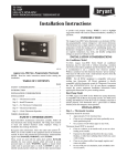
TA85/TA85P
POS Keyboard
User Manual
Edition September 2002
MS-DOS®, Microsoft®, Windows 95®, Windows 98® and Windows NT® are registered trademarks
of Microsoft Corporation.
BEETLE® and SINIX® are registered trademarks of the Wincor Nixdorf International GmbH.
Copyright © Wincor Nixdorf International GmbH, 2002
The reproduction, transmission or use of this document or its contents is not permitted without
express authority.
Offenders will be liable for damages.
All rights, including rights created by patent grant or registration of a utility model or design, are
reserved.
Delivery subject to availability; technical modifications possible.
Contents
Manufacturer’s Declaration and Approval.............................................. 1
General Authorization ................................................................................. 1
FCC-Class A Declaration ............................................................................ 1
User Information.......................................................................................... 2
Safety Instructions....................................................................................... 2
Cleaning Instructions................................................................................... 2
Scope of supply........................................................................................... 3
Mounting keys ........................................................................................... 5
Exchanging the Keys .................................................................................. 5
Inserting Key Labels.................................................................................... 6
Inserting Key Caps ...................................................................................... 7
The TA85/TA85P keyboard....................................................................... 8
General........................................................................................................ 8
Keypad ........................................................................................................ 9
Key switch ................................................................................................... 9
LEDs.......................................................................................................... 10
Swipecard reader (SCR) ........................................................................... 10
Using the Swipecard reader .................................................................. 11
Cleaning Instructions .............................................................................. 11
Connection method ................................................................................... 11
Releasing the Cable Connection ............................................................. 12
Self-test ..................................................................................................... 12
Mounting the BA69.................................................................................... 13
Mounting the BA63/BA66.......................................................................... 14
Connecting a 2nd Keyboard to theTA85P .............................................. 16
Programmable Keyboard TA85P ........................................................... 17
Files on the Diskette.................................................................................. 17
Mode.......................................................................................................... 18
Main functions ........................................................................................... 19
Keyboard Connection ............................................................................... 19
Help ........................................................................................................... 20
Creating Tables .........................................................................................20
Sending and Receiving Tables .................................................................22
Useful Hints ...............................................................................................22
Appendix...................................................................................................24
Technical data ...........................................................................................24
Keyboard layout........................................................................................25
Keyboard Codes (Default) .........................................................................27
Manufacturer’s Declaration and Approval
General Authorization
This device fulfills the requirements of the EEC standard
89/336/EWG “Electromagnetic Compatibility”.
Therefore, you will find the CE mark on the device or packaging.
FCC-Class A Declaration
This equipment has been tested and found to comply with the limits for a
Class A digital device, pursuant to part 15 of the FCC Rules. These limits
are designed to provide reasonable protection against harmful interference when the equipment is operated in a commercial environment. This
equipment generates, uses, and can radiate radio frequency energy and,
if not installed and used in accordance with the instruction manual, may
cause harmful interference to radio communications.
Operation of this equipment in a residential area is likely to cause harmful
interference in which case the user will be requested to correct the interference at his own expense.
Le présent appareil numérique n’émet pas de bruits radioélectriques
dépassant les limites applicable aux appareils numériques de la “Class A”
prescrites dans le Règlement sur le brouillage radioélectrique édicté par le
ministère des Communications du Canada.
GB - 1
User Information
User Information
User Information
Wincor Nixdorf International GmbH (WN) does not accept
responsibility for radio and TV interference and faults that
are caused by unauthorized changes that have been made
to the devices. Furthermore, cables or other devices that
have not been approved by WN may not be connected to
the device. The user is responsible for any faults and interference that are caused as a result.
Repair work on the devices should only be carried out by authorized and
specially trained personnel. Improper repairs will lead to the loss of any
guarantee and liability claims.
Safety Instructions
Note the following safety information:
n
n
n
Lay all cables and supply lines so that nobody can tread on them or
trip over them.
Protect the device from dust, moisture and heat.
Take care to ensure that no foreign objects (e.g. paper clips) or
liquids can get into the inside of the device, as this could cause
electrical shocks or short circuits.
Cleaning Instructions
The keyboard should be cleaned with a germicide from
time to time. Before cleaning in between the keys on the
keyboard with a brush, loosen and remove the key caps
using the key removing device. Do not allow dust to get in
through the open keyboard mechanics.
GB - 2
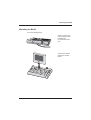
Scope of supply
Scope of supply
Scope of supply
The product includes one TA85 or TA85P keyboard, one user guide and
one accessories kit containing the following:
TA85P
n
n
n
n
n
n
n
n
n
n
n
n
n
1 * triple “0" key cap
1 * double “0" key cap
1 * single “00" key cap
1 * single “0" key cap
1 * single “.” key cap
2 * quadruple variable keys
6 * double variable keys
14 * single variable keys
74 * single transparent plates, 6 * double, 2 * quadruple
Blank sheets for labelling
1 key cap remover
1 set of keys
1 diskette for programming the keyboard
TA85
n
n
n
n
n
n
n
n
n
1 * triple “0" key cap
1 * double “0" key cap
1 * single “00" key cap
2 * quadruple variable keys
6 * double variable keys
60 * single transparent plates, 6 * double, 2 * quadruple
Blank sheets for labelling
1 key cap remover
1 set of keys
The set of keys contains:
Key 1 for key position 1
Key 2 for key positions 1 and 2
Key 3 for key positions 1, 2 and 3
Key 4 for key positions 1, 2, 3 and 4
GB - 3
Scope of supply
The following items can be ordered optionally:
Accessories kit 1:
20 dummy keys (1 x 1)
Accessories kit 2:
6 double variable keys
2 quadruple variable keys
Accessories kit 3:
12 single variable keys
Depending on your order, the keyboard may have a swipecard reader.
If damage has occurred during shipping or if the package contents do not
match the delivery note, promptly notify your Wincor Nixdorf sales outlet.
GB - 4
Mounting keys
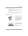
Exchanging the Keys
You can remove each of the key
caps using the key removal device
enclosed, pulling the key upwards.
Place the key removal device on the
selected key until you hear a click.
GB - 5
Mounting keys
Now remove this key from the keyboard by pulling upwards.
If the key that has been removed
carries a number or character, you
can change the lettering as follows:
Using a thin object (e.g. paper-clip
etc.), press upwards against the
plastic cover through the opening on
the underside of the key. Please
refer to the next chapter for instructions on how to insert the new label.
Mounting keys
Inserting Key Labels
Below, you will find instructions on how to insert the key labels:
Transparent key cover
with mat and concave
side up
Each key should be labelled individually. You can use the empty labels
delivered with the system to do so.
Label for keys
Place the written label on the key
cap.
Key cap
GB - 6
Insert the transparent key cover with
the mat and concave side upwards
until it clicks into place in the key cap.
Inserting Key Caps
The labels are replaced as follows:
Remove the key cap from the keyboard (see removing the key cap)
and pull the transparent key cap upwards.
The transparent key cover is then released and the label can be
removed.
Replace the label and fit the transparent key cover (with the mat and
concave side facing upwards) back into the key cap.
Inserting Key Caps
Inserting Key Caps
cam
Insert the key cap in the keyboard
and press firmly into place.
rocker plate
When inserting double or triple keys,
please ensure that the guide cylinder
is on the left in horizontal resp. on
top in vertical position. The quadruple key caps are corresponding with the guide cylinder arranged on
the upper left position.
Ensure when inserting the key caps
that the white cam of the rocker plate
is in the planned bulge of the keyboard.
If you hear a click, the key caps are
inserted correctly.
quadruple key cap with scissors
GB - 7
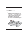
The TA85/TA85P keyboard
General
The TA85 keyboard and the free-programmable version TA85P have a
keypad with maximum 84 usable keys. Except for the numeric keys (0 to
9), the “C” key and the “,” key, the key layout is flexible, i.e. any two contiguous keys can be combined to form a double key and any four keys can
be combined to form a quadruple key, either horizontally or vertically.
The TA85/TA85P keyboard is equipped with a key switch with 6 switch
positions and is available with or without a swipecard reader.
A power-up reset and an automatic self-test are performed each time the
POS terminal is switched on. Following these self-tests, the keyboard is
ready for operation. The keyboard receives its power from the POS
system.
TA85/TA85P keyboard
GB - 8
Keypad
Keypad
Keypad
In the TA85/TA85P keypad, two keys can be combined to form a double
key and four keys to form a quadruple key, either horizontally or vertically.
Only one key code is generated by each double or quadruple key.
Key caps can be changed on the spot using the key cap remover included
in the scope of supply. When using the key caps for multiple keys, note
the position of the pin on the underside, making sure that the desired code
is set. According to the Wincor Nixdorf Convention the guide cylinder is positioned left (double key horizontal), on the bottom (double key vertical) or
on the bottom left (quadruple key).
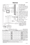
Key switch
Key switch
The TA85/TA85P keyboard is equipped with a key switch with 6 switch positions. Switch position 0 is the basic position; switch positions 1-4 are provided for customer-specific applications. In positions 0 and 1, the key can
be removed.
0
1
T
2
3
4
The sixth switch position, which is
designated on the lock by T, is
intended for use by Field Engineering. From switch position 0, the key
provided can be turned to position T
only. This key is not included in the
scope of supply.
MG
R
02
X
G
RE
03
01
04
Z
The key switch has only one
closure, i.e. there is only one set of
keys for all keylocks that includes the
above-mentioned key variants for the
various switch positions.
T
T
GB - 9
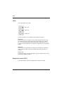
LEDs
LEDs
LEDs
The TA85/TA85P has 3 LEDs:
N
Num Lock
S
Shift Lock
Scroll Lock
They are activated or de-activated by the application software.
Num Lock
When the LED Num Lock lights up the numerical keypad is active ( figures, decimal point and comma) and not the basic level (cursor, “delete”
etc.). You can switch between these levels with the NUM key (also on a
second connected keyboard) or via software, depending on the operating
system.
Shift Lock
When the use of capital letters is activated, this LED lights up. All letters
will be output as CAPS. The other characters are output normally, e.g.
numerics.
Scroll Lock
Scrolling is inactive, when this LED lights up. The scrolling function is only
used by few software programs.
Swipecard reader (SCR)
Swipecard reader
The TA85/TA85P is optionally equipped with a swipecard reader.
GB - 10
Connection method
Using the Swipecard reader
Pull the magnetic card evenly and quickly, from top to bottom, through the
slot on the swipecard reader. Make sure that the magnetic stripe is not
facing the keys.
Note the following precautions when handling magnetic cards:
n
n
n
Never allow magnetic cards to come into contact with liquids.
Never bend or fold magnetic cards.
Never expose magnetic cards to a magnetic field.
Insert the magnetic card in the special slot provided on the
reader from the right-hand side only; inserting the card at
another location could damage the read heads.
Cleaning Instructions
In order to ensure that the quality of reading results is maintained, clean
the swipecard reader at least once a week. To do this, use the special
cleaning card that can be ordered from Wincor Nixdorf.
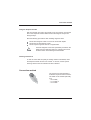
Connection method
Connection method
The connector for the keyboard is
a standard 6-pin mini-DIN connector.
The cable can be ordered optionally
as a
- 0.8 m cable,
- 1.5 m cable or
- 3.0 m cable.
GB - 11
Releasing the Cable Connection
Releasing the Cable Connection
Releasing the Cable Connection
Never remove a cable from a connector socket by simply pulling on the
cable. Always remove the cable by the connector housing. Please follow
the instructions below when removing cables:
n
Turn off all switches to the mains and electrical equipment.
n
Remove all mains cables from the shockproof sockets installed in the
building.
n
Loosen all cables on the electrical equipment.
➀
The mini-DIN connectors are left
plugged in until unlocked.
➁
Using your thumb, pull gently on plastic connector housing ➀, removing
the connector from the socket. This
unlocks the connector. The metal
part of the connector is now visible.
Now remove the connector from the
socket ➁.
Self-test
A self-test of the keyboard is performed each time the POS terminal is
switched on. During this test, the interface to the system is disabled. The
system is informed of the successful completion of the test.
Mounting the BA69
GB - 12
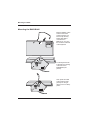
Mounting the BA69
Mounting the BA69
Turn round the keyboard.
There is a gap in the
top, which is stuck on
the keyboard.
Lift up the top with a
coin.
Connect the cashier
display into the keyboard.
GB - 13
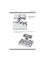
Mounting the BA66
Mounting the BA63/BA66
Mounting the BA66
Before installing, make
sure that the mains
supply has been pulled out. Clip the keyboard cable that is
connected to a
BEETLE or a PC into
the rail at the backside
of the keyboard.
Put the keyboard cable through the opening
of the foot of the
BA63/BA66 (see
picture).
Then press the cable
at the positions (see
picture) into the guidance so that it “disappears”.
GB - 14
Mounting the BA66
Fasten the BA63/BA66
with the two screws at
the keyboard (see
arrows).
Connect the keyboard cable and the screen cable to your BEETLE system
and then switch on the power.
GB - 15
Connecting a 2. Keyboard
Connecting a 2nd Keyboard to theTA85P
Connecting a 2. Keyboard
The TA85P has a connection for a second keyboard for example to plug in
an additional PC-keyboard for text input or for programming the TA85P.
At the backside of the keyboard there is the connection for the second
keyboard, marked “second keyboard”.
Connection 2nd keyboard
Plug the connector into the 2nd connection and secure the cable in that
position with the screw and the metal
cover (see picture).
In the case that the connected 2nd keyboard is a POS-keyboard (TA57, TA61 or Ta64) and that the TA85P uses a
magnetic swipe card reader or a central keylock a simultaneous use of these POS functions on the 2nd keyboard is
not allowed. With the TA85P you can only use the 2nd keyboard alternately (and not at the same time with the 1st keyboard!)
GB - 16
Programmable Keyboard TA85P
By programming the TA85P you have the possibility to flexibly adjust the
keyboard to your special needs.
You can
n
design the keyboard layout according to your needs by - for example moving the numeric block to any place on the keyboard,
n
define several levels for the keycodes, thus using the same key as a
functional key on one level and for text input on another level,
n
port your existing software application with less effort, as you can
keep up the key codes.
Files on the Diskette
The TA85P keyboard is delivered with a diskette containing the following
files:
KBUTI.EXE
Dialogue utility for programming the keyboard
KBUTIHLP.HLP
Help file fot the dialogue utility
SENDKBT.EXE
To send a keyboard table from a file to the keyboard
RCVKBT.EXE
To receive a keyboard table and save it in a file
KB2DEF.EXE
To reset a keyboard to the default state
KBCHKDEF.EXE To check for default state (default or programmed)
TA58DEF.KBT
Default keyboard table for TA58P (!)
GB - 17
Programmable Keyboard TA85P
README.TXT
Readme file for programming the keyboards
TA85P and TA58P
Programming the keyboards TA85P is described in detail in the Readme
file.
Mode
Programmable Keyboard TA85P
The TA85P keyboard work in different modes:
“Windows Mode”
This is the default state of the keyboard
(not programmed)
“DOS Mode”
This state is used by the Retail Device Interface
(RDI), it is entered by rsp. commands from
Windows Mode
“Programmed”
In this state a table has been sent to the keyboard
and is stored in Flash memory; the table controls
what codes are sent for keys and for the
components key lock or magnetic stripe reader
Moreover there are mixed modes possible:
“Programmed”
for the keys
“Windows” rsp.
“DOS-Modus”
for the components key lock, magnetic stripe reader,
The DOS Mode is primarily used by RDI, the Windows Mode is used by
the OPOS components. A description of this protocol can be sent to you
by Wincor Nixdorf on request. When developing new software you should
generally use the Windows Mode.
GB - 18
Programmable Keyboard TA85P
Main functions
The dialogue utility KBUTI.EXE serves to:
n
programming the codes for the keys and the components key lock,
magnetic stripe reader
n
send a keyboard table to the keyboard
n
receive a table from the keyboard and to store it in a file
n
reset a keyboard into its default state, i.e. Windows Mode and default
codes for the keys
n
check for keyboard state (default or programmed)
So the functionality of the programs
n
n
n
n
SENDKBT.EXE
RCVKBT.EXE
KB2DEF.EXE
KBCHKDEF.EXE
is part of the dialogue utility. These 4 programs therefore are intended to
be used in conjunction with .BAT files. They return values that can be
checked using ERRORLEVEL. The values returned together with an example you will find in the Readme file.
Files containing keyboard tables for TA85P have by convention the extension .KBT.
Keyboard Connection
To program a TA85P keyboard connect this directly to the BEETLE system (or a PC with Mini-DIN connector). This interface is named the primary keyboard interface. A standard PC keyboard, TA57 or TA58 then is
connected to the secondary keyboard interface of the TA85P. So the
TA85P has a keyboard wedge, whose inputs are not equivalent. Commands from the system are sent to the primary interface and may then be
GB - 19
Programmable Keyboard TA85P
transferred to the secondary interface. A reaction of the system to a key
stroke, is transmitted to the keyboard, whose key became operated - thus
pressed or released.
Help
The dialogue utility KBUTI.EXE has a context sensitive help, which is activated as usual with the F1 key.
Creating Tables
The creation of tables with the utility KBUTI.EXE can be done
n
n
n
n
under DOS
in DOS Mode of Windows 9x
in a DOS window of Windows 9x
and in a DOS window of Windows NT
Sending and Receiving tables, however, is only possible under DOS or
Windows 9x. The restrictions of Windows NT do not allow it.
The creation of tables request a mouse.
It is possible to define up to 4 keyboard levels. They may be dependent of:
n
n
n
freely defined level keys (POS Shift levels)
Ctrl, Alt, AltGr state
CapsLock and/or ScrollLock state
You can define simple codes, codes in Shift state, key combinations
strings built from that like e.g.:
n
n
n
n
n
GB - 20
a
A
*
00
{Ctrl+F5}
Programmable Keyboard TA85P
n
n
n
n
{Shift+F8}
{Alt+F1}
{Alt+#123}
{Ctrl+f}{Alt+#240}
For a number of codes symbolic names are available, like F1, .., F12,
Shift, Ctrl, Alt, AltGr, Enter, Return, Left, PgUp etc.
Specification of codes not only may be done in symbolic form like above,
but also as hexadecimal 8042 scan codes. This, however, is only in a few
cases required and will make sense!
Specifying hexadecimal scan codes should be avoided at
all, unless there are good reasons! A fairly good knowledge
of their structure and all their details is required!
Before programming the following is to be defined:
n
n
n
Target keyboard TA85P (can not be changed later)
Keyboard language, e.g. US for USA, GR for Germany etc.
Type of level selection (none, POS Shift, Ctrl/Alt/AltGr, CapsLock/ScrollLock)
Specification of the keyboard language is required to allow the keyboard
to deliver such codes, that can be interpreted later correctly by the language keyboard driver for the rsp. country. The target configuration is important, not the configuration at the time when the table is created.
For the codes of the key lock and the data of the various tracks of the magnetic stripe reader, header and trailer codes can be programmed. This allows the application to distinguish those from normal key strokes.
The codes assigned can be viewed key by key (also with Autoincrement)
with the help of KBUTI.EXE. They also can be shown in a more compact
form on the screen or for documentation purposes can be written into a file
with extension .TXT or directly be sent to a printer (LPT1).
GB - 21
Programmable Keyboard TA85P
Sending and Receiving Tables
The codes assigned are stored in a file with default extension .KBT. Such
files can be loaded by the dialogue utility KBUTI.EXE and the tables sent
to the keyboard. They also can be sent directly from such files by the
batch utility SENDKBT.EXE. Accordingly KBUTI.EXE may receive a table
from the TA85P, which then can be viewed or stored in a .KBT file. This,
however, can also be done using RCVKBT.EXE by specifying the file
name as a parameter.
During transmission of tables no keyboard activity is allowed, such as key presses or key position change otherwise
the transmission may be influenced badly!
Useful hints
Programming keyboards by tables allows a very flexible keyboard layout.
However, one should have some thought about the task of a technician in
the field! From logistics point of view it should be ensured that:
n
n
Spare keyboards are delivered always loaded with customer specific
tables
with starting the system the tables are loaded automatically
The batch utilities
n
n
n
n
SENDKBT.EXE
RCVKBT.EXE
KB2DEF.EXE
KBCHKDEF.EXE
are provided especially for this situation to allow support of the technicians. However, the programs alone are not helpful for a technician!
Instead they should be available dependent on the solution on disks together with rsp. tables at the site. Also they should be executable with the resources available there!
GB - 22
Programmable Keyboard TA85P
Take care, that there must not be any keyboard activity when they are
executed! This has to be strongly observed, if such a utility is run automatically at start of the system! This at least requires proper error handling
rsp. retries in the execution of .BAT files.
Double, Triple, and Quad keys only have a cylindric part responsible
for generating the respective code. So it is useful to assign the code
to all possible positions covered by a key.
GB - 23
Appendix
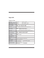
Technical Data
Housing
dimensions / Weight
Footprint:
Height:
280mm * 189mm
54mm; Weight: 1.16 kg
Cable length
Optional:
0.8 m, 1.5 m or 3.0 m
Power supply
TA85: 5V +/- 20%, max. 140mA
TA85P: 5V +/- 10%, max. 170mA
Protocol
PC AT interface, bidirectional, serial, synchronous
Connection
TA85: Mini-DIN connector (6-pin.)
TA85P: 1 Mini-DIN connector (6-pin.)
1 Mini-DIN connector for the 2. keyboard
Keyboard
Keyboard with variable key assignment, two-key rollover*
Microprocessor
TA85: CMOS-CPU 87C51FA, 12MHz
TA85P: CMOS-CPU C515A, 12MHz
FlashROM
TA85: TA85P: 32 KByte
Power-up reset
Yes
Self-test
Yes
LEDs
3 (Num Lock, Shift Lock, Scroll Lock)
Technology
CMOS, standard TTL
Key switch
Switch positions:
Swipecard reader
Number of tracks :
3
Magnetic card coding: to ISO 7811/2
Reading rate:
15 to 80cm/s
GB - 24
5 plus insertion position
Keyboard layout
*Only two keys pressed at the same time are accepted. With the simultaneous operation of more than two keys the third and all further keys are
suppressed.
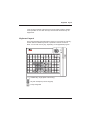
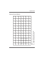
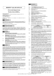
Keyboard layout
Keyboard layout
This is the keyboard layout delivered ex works. It is the same for both keyboards. With the TA85P keyboard it is possible to shift the numerical
block. You can also use any key, depending on the applicated program.
T
P
1
N
2
S
3
4
C 7 8 9
4 5 6
1 2 3
,
Labelled key, single (fitted at the factory)
9
Key with inscription (numeric keypad)
Freely assignable
GB - 25
Keyboard layout
A useful assignment of the TA85/TA85P in the default setting:
0
0
00
0
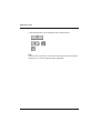
Note
In these cases only the key “0" as ASCII-Code is given from the keyboard.
Other keys (”0") must be evaluated before application.
GB - 26
;
27
27 3b
BS
0e
0e 08
CUp
e0 48
48 e0
Space
39
39 20
CDn
e0 50
50 e0
4a
4a 2d
/
35
35 2f
ESC
01
01 1b
Home
e0 47
47 e0
CLft
e0 4b
4b e0
End
e0 4f
4f e0
+
4e
4e 2b
0
52
52 30
PgDn
e0 51
51 e0
CRgt
e0 4d
4d e0
PgUp
e0 49
49 e0
F1
3b
3b 00
=
0d
0d 3d
2
03
03 32
r
13
13 72
1
4f
4f 31
4
4b
4b 34
7
47
47 37
F2
3c
3c 00
[
1a
1a 30
3
04
04 33
s
1f
1f 73
2
50
50 32
5
4c
4c 35
8
48
48 38
F3
3d
3d 00
\
2b
2b 5c
4
05
05 34
.
53
53 2e
3
51
51 33
6
4d
4d 36
9
49
49 39
F4
3e
3e 00
]
1b
1b 5d
5
06
06 35
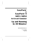
Legend
ESC
behaviour, provided US keyboard driver is in use
01
Code INT 15h level (scan code, only make code)
01 1b Code INT 16h level (scan code, ASCII code)
1
02
02 31
0
0b
0b 30
u
16
16 75
CR
1c
1c 0d
g
22
22 67
a
1e
1e 61
F5
3f
3f 00
,
28
28 27
6
07
07 36
v
2f
2f 76
m
32
32 6d
h
23
23 68
b
30
30 62
F6
40
40 00
`
29
29 60
7
08
08 37
w
11
11 77
z
2c
2c 7a
i
17
17 69
c
2e
2e 63
F7
41
41 00
.
34
34 2e
8
09
09 38
x
2d
2d 78
o
18
18 6f
j
24
24 6a
d
20
20 64
F8
42
42 00
\
56
56 5c
t
14
14 74
y
15
15 79
p
19
19 70
k
25
25 6b
e
12
12 65
F9
43
43 00
*
37
37 2a
F11
57
85 00
n
31
31 6e
q
10
10 71
l
26
26 6c
f
21
21 66
F10
44
44 00
0c
0c 2d
F12
58
86 00
Keyboard Codes
Keyboard Codes (Default)
Keyboard Codes
GB - 27