1
Interactive Rocks
Rob Davison
BSc Computer Science/Music
2003/2004
The candidate confirms that the work submitted is their own and the appropriate credit has
been given where reference has been made to the work of others.
I understand that failure to attribute material which is obtained from another source may be
considered as plagiarism.
(Signature of student)___________________________________
Summary
The aim of this project is to produce interactive multimedia software for the Yorkshire Quarry
Arts Project. Yorkshire Quarry Arts is a feasibility study aiming to identify opportunities for
regenerating new sustainable landscapes in Yorkshire. Yorkshire Quarry Arts (YQA)
obtained a variety of mineral rocks, some of which create audible chimes when struck in
different places. The sound of each rock differs due to its organic structure.
At the initial stage, YQA required a multimedia application for their website, with the
possibility of a ‘hands on’ element as an extension to the project. The ‘Interactive Rocks’
software enables visitors to the YQA website to hear how many of these different rocks sound
when struck. Visitors are also able to create their own musical compositions, which can be
recorded and played back when required.
This project investigates relevant software, research, tools and techniques before designing
and implementing an original piece of software for YQA.
This project creates a form of ‘entertainment’ for website visitors. It may form the basis of
further work, such as researching links between the sound and organic structure of different
rocks.
i
Acknowledgements
I would like to thank my supervisor Dr Kia Ng for his advice, assistance and access to the lab
over the last 7 months. I would also like to thank Bobbie Millar, the manager of the Yorkshire
Quarry Arts project for her suggestions and assistance throughout the project, and her input in
evaluating the software. Thanks also goes to Vickee Watson for integrating the software with
the YQA website and for cheering me up in the lab! Finally, I would like to thank all of my
family and friends for their support, proof-reading and testing throughout the entire project.
ii
Contents
1 Introduction
1
1.1 Context .............................................................................................................1
1.2 Objectives.........................................................................................................2
1.3 Project Evaluation ............................................................................................2
1.4 Methodology ....................................................................................................3
1.4.1
Introduction .....................................................................................3
1.4.2
The Waterfall Model .......................................................................3
1.4.3
Iterative and User Involvement Methods ........................................3
1.4.4
Methodology Chosen.......................................................................4
1.5 Project Plan ......................................................................................................5
2 Background Reading
6
2.1 Introduction......................................................................................................6
2.2 Similar Projects and Research..........................................................................6
2.3 Human Computer Interaction...........................................................................8
2.4 Pitch Shifting....................................................................................................8
2.4.1
Fast Fourier Transform....................................................................8
2.4.2
Phase Vocoder ...............................................................................10
2.4.3
Byte Manipulation .........................................................................10
3 Project Design
11
3.1 Introduction....................................................................................................11
3.2 Tools and Technologies .................................................................................11
3.2.1
C++ ................................................................................................11
3.2.2
Visual C++.....................................................................................11
3.2.3
Java ................................................................................................12
3.2.4
Tools chosen ..................................................................................12
3.3 Sensor interfaces ............................................................................................12
3.3.1
MIDI ..............................................................................................12
3.3.2
Microphone....................................................................................13
3.3.3
Sensor Interface Chosen ................................................................13
iii
3.4
Class Design...................................................................................................14
3.4.1
UML ..............................................................................................14
3.4.2
Class Diagram ...............................................................................14
4 Implementation
17
4.1 Graphical User Interface ................................................................................17
4.2 Mouse Events .................................................................................................18
4.3 Hit Spots.........................................................................................................18
4.3.1
Displaying......................................................................................18
4.3.2
Recording and Saving....................................................................19
4.3.3
Loading and Playback ...................................................................19
4.4 XML ‘Rock’ Files ..........................................................................................20
4.4.1
XML ..............................................................................................20
4.4.2
Rock Files ......................................................................................20
4.4.3
Java XML Parsers..........................................................................21
4.5 Sound Loading, Capture, Processing and Playback......................................21
4.5.1
AudioClip ......................................................................................21
4.5.2
SoundList and SoundLoader .........................................................21
4.5.3
Audio Capture ...............................................................................22
4.5.4
Byte arrays and Processing............................................................22
4.5.5
Playback ........................................................................................23
4.5.6
Touchscreen...................................................................................23
5 Evaluation
24
5.1 Introduction....................................................................................................24
5.2 Evaluation with Yorkshire Quarry Arts .........................................................25
5.3 User Tests.......................................................................................................26
5.3.1
General Impressions ......................................................................26
5.3.2
Erroneous Hit Spots.......................................................................26
5.4 Evaluation of Tools and Implementation Methods........................................27
6 Conclusion
28
6.1 Conclusion .....................................................................................................28
6.2 Future Directions............................................................................................29
References
31
Appendix A Personal Reflections
33
Appendix B Project Plan
34
Appendix C User Manual
35
iv
Chapter 1
Introduction
1.1 Context
This project is in the field of computer music and digital signal processing (DSP). The aim of
the project is to design and develop a piece of interactive multimedia software based on the
sound of mineral rocks, as required by the Yorkshire Quarry Arts (YQA) project. YQA
acquired a variety of different mineral rocks, many of which produce audible tones when
struck. The tone produced depends on the rock’ s organic structure. The YQA project required
a form of interactivity on their website, and hence this project developed an online interactive
prototype to enable the visitors of the YQA website the opportunity to hear the natural sound
of some of these rocks. Beside direct interaction (i.e. a user interacts with the software
prototype and the prototype provides a form of multimedia feedback), the prototype also
provides functionality to record live interactions. This function allows “musical
compositions” to be recorded to file for playback at a later time.
This project is therefore called the Interactive Rocks (iRock) project.
The software presents a graphical interface that shows the texture image of the rock being
played. Each time the rock is ‘hit’ (mouse click), a spot is drawn on the screen to represent
this. The software can handle two forms of audio; audio that is read from a file, and audio that
is digitised live from a sensor (e.g. microphone or other sensors). The software also allows the
user to change the type of rock that they hitting, by loading new rock details from a file.
This project forms the basis of future interdisciplinary work that YQA may undertake. For
example, links between the sound produced by a rock, and its organic structure could be
investigated. This project only concentrates on what is hoped to be an ‘entertaining’
application for the general public to try when visiting the YQA website. It is possible that the
application could be linked to educational resources on the YQA website in the future.
1
1.2 Objectives
The objectives of this project were (with minor alterations) as agreed in the mid-project
report:
•
Learn graphical interfaces such as javax swing components
•
Learn how to handle various user input types in Java such as mouse clicks and audio
•
Investigate the possibility of various types of pitch shifting such as FFT and phase
vocoding
•
Learn how sensors interface with an application.
In order to achieve these objectives, the following minimum requirements were determined:
•
A software application is produced that uses a point and click interface for the sound
of a mineral rock
•
Audio manipulation algorithms respond to the user’ s inputs
•
The system is evaluated for latency and usability
•
The ability to record, save and load “Rock Compositions” that the user has performed
The following possible extensions to these requirements have been identified:
•
Use of physical, electronic sensors as an interface to the mineral rock, for physical
exhibitions.
•
Use of a touch screen interface
•
If similar products are available to test, then the system can be compared with them
for latency and ease of use.
Originally, evaluation was only required for the latency of the system, however it was thought
that a formal evaluation with YQA for satisfaction and usability would also be necessary.
1.3 Project Evaluation
Due to the nature of the software’ s interactivity, it was difficult to determine quantitative
criteria for evaluation. The latency of the user input to audio output was the most obvious
method of evaluating the software. Some basic user tests and the satisfaction of Yorkshire
Quarry Arts were also considered.
2
The project was also evaluated in terms of methodology and the chosen solution. This is
discussed further in the evaluation chapter itself.
1.4 Methodology
1.4.1
Introduction
It was necessary to choose an appropriate methodology for the Interactive Rocks project. The
section below discusses some common methodologies, and which, if any were suitable for the
project.
1.4.2
The Waterfall Model
Software engineering now has many different methodologies and life-cycles. ‘The waterfall
lifecycle was the first model generally known in software engineering and forms the basis of
many lifecycles in use today’ [17], often known as the ‘one shot’ or ‘once through’ process
[7]. This method is linear in nature, requiring each stage to be completed before the next one
can start. These five stages are named; requirements Analysis, Design, Code, Test and
Maintenance. Preece [17] describes how such a method is fundamentally flawed, as it fails to
take into account that the requirements will change as the project progresses. As the waterfall
method became more widely used, feedback was introduced into the model. Iteration is now
commonplace in most or all of the waterfall stages. Preece [17] comments on the issue of
failing to incorporate the users into this feedback process, meaning that a more flexible
method may be required. This methodology was not appropriate for the project, as it fails to
consider the changing requirements from YQA.
1.4.3
Iterative and User Involvement Methods
“Interactive Rocks” was developed for Yorkshire Quarry Arts. Ideally, YQA should have had
input at each stage of the project. Once the basic requirements were met, YQA was very
flexible to any additional functionality. As long as the application had a form of user
interaction and processes the audio sufficiently, the requirements were deemed as met. In
order to produce further functionality, it was important that meetings with Yorkshire Quarry
Arts took place on a regular basis in order to obtain feedback and further consolidate these
additional requirements.
The spiral model was proposed by Boehm in 1988. The two main advantages of following
this methodology are risk analysis and prototyping. ‘… [prototyping] allows ideas and
progress to be repeatedly checked and evaluated‘ [17]. Hughes and Cotterell [7] claim that
this method is simply another way of looking at the waterfall model. It is certainly true that it
is possible to escape the process after the completion of any activity. The cycles seem to give
3
more opportunity for iteration however, making it more ideal for changing and developing
requirements. The spiral methodology was therefore a little more suitable for this project, as
new ideas for the software could be checked after they were initially implemented.
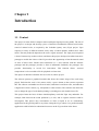
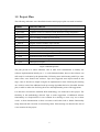
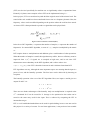
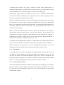
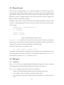
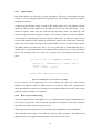
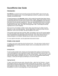
Rational Software has developed a model called the ‘Rational Unified Process’ (RUP). This
process performs many iterations of the waterfall model, as can be seen in figure 1; the four
types of iteration being inception, elaboration, construction and transition.
ID
1
Task Name
1st Iteration: Inception
2
2nd Iteration: Elaboration
3
3rd Iteration: Construction
4
4th Iteration: Transition
5
Business Modelling
6
Requirements
7
Analysis and Design
8
Build
9
Test
10
Deployment
November
December
January
February
March
April
Figure 1. The Rational Unified Process [9]
Johnson [9] says that this model is ideal for large and complex software systems, the first
iterations having a high level of abstraction, the latter ones being more detailed. The
methodology can still be applied to smaller scale software where requirements need to be
clarified and expanded on regularly, which made it ideal for this project.
1.4.4
Methodology Chosen
A modified version of the RUP was appropriate for this project. The business modelling was
not required in this project. The requirements changed after each iteration, and the software
could only be deployed in the latter iterations when a suitable website had been set up. This
revised method was suitable as it enabled Yorkshire Quarry Arts and potential users to give
feedback and suggest extra functionality on a regular basis. It enabled functionality of the
software to gradually increase, whilst being tested and verified by YQA.
4
May
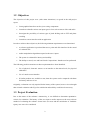
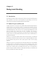
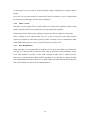
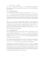
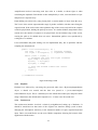
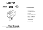
1.5 Project Plan
The following milestones were identified when the initial project plan was made in October:
Deadline
st
31 October
th
5 December
Task to be achieved
Finish preliminary research on problem so prototype can be started
Complete a basic Java interface with interactive swing components
th
Implement one basic audio processing effect
rd
Have recordings of different rock sounds
th
Implement an interface with a sensor
th
Integrate software with the YQA website
th
Implement record/save/playback functions of rock ‘tunes’
th
Demonstration of progress to supervisor and assessor
th
Demonstration and initial testing with YQA
th
Further Audio Processing
th
Implement touch screen interface
th
Evaluate software with YQA
th
Submit project report
16 January
23 January
27 February
12 March
19 March
19 March
16 April
16 April
16 April
19 April
28 April
Figure 2. Initial Project Plan
The plan proved to be rather ambitious. Due to other work commitments in January, the
software implementation initially ran 1 – 2 weeks behind schedule; however the software was
still ready for evaluation by the planned date. Following some initial testing with YQA, some
minor errors were found in the software. YQA also suggested some improvements at this
stage, some of which were simple enough to be implemented in time. Following this meeting
on 15/04/04, some of the additional audio processing algorithms had to be discarded from the
plan, in order to make time for fixing the errors and implementing some of the suggestions.
It is therefore clear that the modified RUP methodology was followed for this project. The
flexibility in this methodology allowed YQA to make suggestions of additional software
functionality on a frequent basis. It was common for a meeting to occur every two or three
weeks. A short demonstration on these occasions would often lead to further functionality
being discussed and a decision on action being taken. Each meeting was therefore the start of
a new iteration for the project.
5
Chapter 2
Background Reading
2.1 Introduction
This chapter gives details of other research projects, which are relevant to that of the proposed
iRocks application. It also looks at various approaches for pitch shifting; one of the most
common but not necessarily easiest digital signal processing technique.
2.2 Similar Projects and Research
Verplank [22] describes several projects using a MIDI (Musical Intstrument Digital Interface)
controller interface. One such project describes an accordion like mechanism with three
continuous degrees of freedom, and buttons on each end. He describes how an on board stamp
sends MIDI information to a Mac. This device uses a specially designed MIDI stamp. For this
project, the simplest form of audio sensor was used; a microphone. This accordion is
described as the most complete of all the projects, involving an innovative design of the MIDI
controller. There was a small possibility that Interactive Rocks could use a MIDI interface as
an extension to the project.
Wilkerson et al. [23] propose a MIDI controller titled The Mutha Rubboard. The Rubboard
has similarities to this project in that it uses piezo sensors to output both MIDI and raw data;
the main difference being that the sensors require physical contact with the playing
implement.
Wilkerson et al [23] go on to describe how the raw data input method can be used with MIDI
for masking latencies; a useful addition to this project. Percussive mappings are able to reflect
the rhythmic and percussive nature of how the Rubboard is played. The Rubboard project is
useful in that it combines both raw and MIDI data from the source. It was hoped that if
possible, this project could have followed a similar path so that latency was minimised, and
the user is presented with a seamless audio output.
6
The Accordiatron [6] is similar to the device described by Verplank [22]. They claim that the
output of the Accordiaton is much more than that of a normal accordion as it can control any
aspect of the sound using a real time audio control environment.
A standard 5 pin MIDI socket is able to connect the instrument with any MIDI receiving
device, making the Accordiatron ultra-portable. The YQA project tried to benefit from such
compatibility, by using a standard microphone interface to the computer’ s sound card.
The Accordiatron uses a separate channel for each of the three continuous controllers. Each
channel is assigned a value from 0 – 127 in conjunction with the 7 bit MIDI standard. It
should be noted that the Accordiatron only responds to changing data; repetitive data is
essentially ignored. The data is therefore not strictly continuous, but can handle up to 1000
changes per second. It is hoped that similar performance on this project will be sufficient
enough to produce a good quality output. The latency of any raw or MIDI data shall depend
on the efficiency of the platform and audio algorithms implemented.
The Accordiatron’ s buttons have no value to the YQA instrument, as they transmit a ‘note-on’
event when pressed, and a ‘note-off’ event on release. The mineral rock differs in that it
responds only when it is hit, and how hard it is hit (velocity). A ‘note-off’ event is not
required. Raw audio is naturally continuous, so was treated differently (chapter 4).
Hunt and Kirk [8] developed a system in 1987 called MidiGrid. Despite its age, its features
are remarkably similar to those of this project.
MidiGrid had been designed to be used by children, especially those with special needs,
where it has “become the primary instrument for several people with disabilities”. Its simple
user interface has enabled the product to prolong its lifespan, despite large technological
advances in this area. Its main difference with the Interactive Rocks project is that it outputs
MIDI events only. The Interactive Rocks system manipulates raw and stored audio, rather
than just playing back a MIDI event.
Each box on the grid plays a different sound; chords, sequences and single notes are possible
and denoted by the concentration of dots in each. The range of physical movement necessary
to change the sound can be modified to suit the needs of the player. A similar extension was
considered (but not implemented) for this project, which would have made it more accessible
to the user.
Hunt and Kirk [8] then comment on Music Mouse; a similar product that, as its name
suggests, triggers events in response to mouse movements and clicks. Music Mouse differs in
that it uses intelligence to interact with the user’ s improvisation. In essence, “Music Mouse
7
joins in your improvisation, whereas MidiGrid simply reproduces the stored material on
demand.”
The Interactive Rocks project sits in the middle of these two ideas. It does not ‘join in’ as
such, but audio is manipulated according to the input, so neither does it just reproduce stored
audio.
2.3 Human Computer Interaction
Human Computer Interaction (HCI) has always commanded a large proportion of active
research in computing, so it is worth mentioning some of the methods appropriate to the
project here.
[11] claims that “ The
technologies
and
increasing
analog
to
availability
MIDI
interfaces
of
new
has
sensing
lead
many
people to assert that there are no reasons to do ‘mouse music’
any more”. However he goes on to say that “ low cost, widely available
input devices such as mice, joysticks or computer keyboards
should not be considered obsolete”.
‘Music Mouse’ [5] is an instrument in its own right, and designed to be played just with the
mouse. Interactive Rocks is similar, in that the graphical interface does not attempt to
“ emulate any sliders or knobs” which are often seen in mouse music. Sliders and knobs on
GUIs will never compare to their physical equivalents; playing instruments with these
features on a GUI may inhibit the performer’ s creativity.
It is hoped that the simplicity of the Interactive Rocks interface will enable accessibility to all
users. The possibility of a touch-screen makes the instrument much more playable.
2.4 Pitch Shifting
2.4.1
Fast Fourier Transform
Fourier’ s theory states that any waveform can be deconstructed into a combination of simple
sine waves of varying amplitudes, frequencies and phases.
‘Fourier analysis detects the harmonic components of a sound using a pattern matching
method.’ [13] Roads [19] also provides a good overview of Fourier transform.
Up until the 1960’ s, Fourier Transforms such as the Discreet Fourier Transform (DFT) were
complex and time consuming tasks, both by hand and computer. Fast Fourier Transform
8
(FFT) was devised specifically for machine use to significantly reduce computational time.
Kientzle [12] shows some examples of how FFT can be implemented using C++.
In this project, FFT was considered to pitch-shift the original sound of the mineral rock. The
sound of the rock would have been transferred from a time to a frequency domain. Here, the
frequency values can be modified depending on the position where the rock has been struck.
An inverse FFT is then performed to produce a signal that can be played back.
Figure 3. Discreet Fourier Transform (DFT)
In the above DFT algorithm, n represents the number of samples, k represents the number of
frequencies. In a normal DFT algorithm, a vector of x[n] samples is multiplied by the matrix
WN.
DFT requires about N2 multiplications and additions, plus a small number of other operations.
When the number of samples is small, this algorithm may suffice, however efficiency must be
improved from O(N2) if signals are to sampled at high rates, and in real time. FFT
demonstrates some redundancy in the DFT algorithm, and is able to reduce it to
O(N x log2(N)) time. FFT is therefore between 10 and 1100 times faster than DFT.
FFT algorithms can vary, although the most important aspects are ensuring that the input is a
power of two, and the butterfly operation. The first issue can be dealt with by throwing an
exception.
The butterfly operation is the core of the FFT algorithm. Here, two inputs A and B give two
outputs X and Y via:
X = A + WnkN B
Y = A - WnkN B
There are two distinct advantages of the butterfly. Only one multiplication is required as the
WnkN calculated for X can be reused for Y. Storage is also optimised as the results can be
stored in the same array used for the input. This is achieved by computing the FFT in
intermediate stages.
FFT is a well established method that can be used for pitch-shifting, however was not used in
this project for a variety of reasons. For real time applications, it may not have been suitable
9
for this project. It is best used on simple monaural samples; anything more complex adds to
latency.
Java uses a lot of system resources; combine this with overall latency, and it is possible that
the software would struggle with real time computation.
2.4.2
Phase Vocoder
The phase vocoder applies FFT to small segments of a sound. The segments usually overlap
and the original sound can be reproduced by piecing together the segments.
Pitch transposition is achieved by scaling the frequencies of the re-synthesis components.
Phase vocoding is more efficient than FFT as it is able to keep the audio output flowing
despite any complexity of the input signal [19]. Phase vocoding was also considered for audio
manipulation in this project, but was rejected for similar reasons to FFT.
2.4.3
Byte Manipulation
If the audio that is to be manipulated is sampled at 8 bits, then each sample is represented by
one byte. It is then possible to perform a wide range of audio processing techniques at byte
level. This method is restrictive in that audio sampled at other rates is rendered useless.
However it is much faster than DFT and FFT algorithms as it is possible to compute in linear
time. Manipulating the audio at byte level is much simpler and more efficient than using FFT,
and so this method was chosen for the implementation.
10
Chapter 3
Project Design
3.1 Introduction
This chapter builds on the last by discussing a variety of tools and technologies considered for
implementation when the software was initially being designed. It then discusses in detail
some of the sensor interfaces identified in chapter 2. Finally, it looks at UML and shows how
the software was developed using an object-oriented approach. A basic outline of the class
design is shown. This is followed by short paragraphs explaining the function of each class.
3.2 Tools and Technologies
3.2.1
C++
C++ is an object-oriented version of the C programming language. It builds on C’ s procedural
past, adding the object-oriented approach. It is arguably the most used programming language
in current use, improved with its recent ANSI/ISO approval. C++ is still platform dependant
however, meaning that code must be compiled separately for different operating systems.
‘…there
are
compilers
many
and
problems
different
among
different
computers
that
C
and
can
C++
make
portability difficult to achieve.’ [2].
C++ was considered for this project; however it lacks support for the Internet and is not
portable. YQA project require an application that can be embedded in their website, therefore
other languages were considered.
3.2.2
Visual C++
Visual C++ is a Microsoft application designed to bring C++ programming to a WIMP
environment, rather than the archaic text editor/command line interface. It does take a little
time to learn how to use the program, but once proficient a developer can enjoy the ‘class
wizard’ tool among others to increase productivity.
11
Visual C++ will suffer from similar disadvantages to ANSI C++. It only produces code to run
on a Microsoft platform and would be useless for Linux or Mac users. Despite the benefits
that it may bring in the long term, Visual C++ provides no obvious advantages over ANSI
C++, and for similar reasons was not suitable for this project.
3.2.3
Java
Java was developed in 1992 by Sun Microsystems. It is similar to C++ in syntax, but has
many advantages over it. Java has been specifically designed for the Internet, supporting
multimedia and networking much more than its competitors. Eckel [3] claims that Java has
produced amazing reductions in development time, also tackling issues such as cross –
platform and security. Java also introduces applets; small programs that can be embedded into
a web browser. It does not inherit any legacy that C++ might from C, and boasts an extensive
on-line API documentation.
3.2.4
Tools chosen
Java was chosen as the programming platform for this project. The iRocks application can be
used on the Internet as part of the YQA website. Java applets are ideal for this task, requiring
minimal code change from that of a standard application. Java also simplifies graphical
interfaces and audio playback, meaning that more time can be spent on other aspects of the
project. These graphical interfaces are documented thoroughly with all of Java’ s standard
library classes [20].
Efford [4] comments on some advantages of using Java applets: ‘They are not
complete applications, and can easily be embedded into an HTML
page, then downloaded by HTTP’
He also comments that applets run on the local machine, and have ‘restricted rights’ . The
YQA website must be secure at all times, and would benefit from secure Java applets.
3.3 Sensor interfaces
3.3.1
MIDI
‘MIDI (Musical Instrument Digital Interface) is an archaic, yet effective technology originally
used to connect keyboard controllers to computer devices. It has recently been used in the
design of new musical instruments to a great degree of success.’ Combined with the increase
in computational power, it has allowed real time interaction such as composition,
interpretation and improvisation to become a reality [10].
For this project, MIDI was considered as an interface between the mineral rock and computer.
12
A standard setup would be one where a keyboard or other such recognised device is
connected to the computer via a MIDI cable. On each key-press, discrete data such as ‘pitch,
velocity and duration’ are sent to the computer, which acts accordingly [18].
In this project, physical sensors would have been able to receive vibrations from the mineral
rock, and convert this to a MIDI signal. The application will receive these signals, process the
data, and consequently output the processed audio.
MIDI has disadvantages in that it is limited in bandwidth and musical expressiveness. Roads
[18] describes that it takes 320ms to transmit one MIDI word. Moore [14] comments that
heavy use of continuous controllers such as pitch bend, foot-pedals and breath controllers can
overwhelm a MIDI connection. This can make a virtuoso performance suffer from loss of
signal, or latency of output.
MIDI can deal with continuous input, which is required for this project. An example of
discreet inputs would be where the rock is hit in several places at various velocities. The
controller can convert the vibrations to simple MIDI events, and transmit to the computer. A
continuous input would be where the rock was hit, and the beater dragged around on its
surface. This is analogous to a glissando (slide) on a violin.
An extension to the MIDI method would be to transmit the raw audio data directly to the
sound card. This could then be analysed and dealt with by the application more efficiently.
MIDI was ideal for this project due to its wide compatibility and simplicity, but was not
implemented due to the amount of time required to physically construct a setup.
3.3.2
Microphone
A microphone provides a much more portable and readily available setup for YQA to use for
an exhibition. The microphone is physically connected to the soundcard via a jack or minijack lead. The latency associated with MIDI no longer exists; however microphones and
soundcards will always produce noise which is naturally unwanted when processing further
effects. To combat this, high quality hardware should be used when available.
3.3.3
Sensor Interface Chosen
After much deliberation and despite a MIDI setup seeming more challenging, a microphone
setup was decided as the best method for capturing audio. It kept in line with the idea of using
raw audio that can be manipulated at byte level, and is also the simplest and most widely
available form of sensor.
13
3.4 Class Design
3.4.1
UML
Java is an inherently object oriented programming language, so it was sensible to design the
software using this approach. UML is a semi-formal method designed to visualise the design
of a system in diagrammatical form [1]. It is possible for all of the stakeholders of a project to
be involved with the design of a project regardless of their technical knowledge. [15] says that
UML is widely used, and essential in large projects. “ A [UML] model plays the analogous
role in software development that blueprints and other plans play in the building of a
skyscraper” [15].
The Interactive Rocks project is relatively small, and due to limited contact time with YQA, it
was not feasible to include UML during the project meetings. A simple class diagram is
included below, followed by an explanation of each original class.
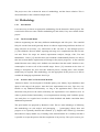
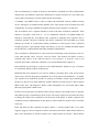
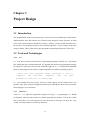
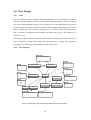
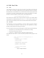
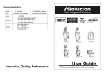
3.4.2
Class Diagram
javax.sound.sampled
java.awt.event
Aud ioInput
Aud ioC apture
java.awt.image
has a
javax.swing
java.awt.geom
RockImage
YQA
XMLParser
java.util.Array
List
uses
SoundList
FFilter
ja va x.xml.pa rsers
So undLoader
org.xml.sax
FFilter2
javax.swing.filechooser
java.applet.AudioClip
Figure 4. Class design with java package dependencies for ‘Interactive Rocks’
14
YQA
This is the main class for the Interactive Rocks software. It provides the Graphical User
Interface part of the software, and holds instances of all the other classes used. More
importantly, it provides the methods that listen for events such as a mouse or button click,
which
in
turn
triggers
other
events.
Some
important
methods
include
startLoadingSounds() which is always called when the application is first run and
when a different rock is chosen; and playSound(int, int, int) which plays a
specified rock sound dependant on the x and y co-ordinates of the mouse, and the button
pressed.
RockImage
This class deals with drawing the image of the rock on to the screen, as well as small dots
called ‘hit spots’ where the rock has been hit. It also includes methods for recording and
playing back a sequence of hits (ie a ‘Rock composition’ ). The most important method in this
class is paint(Graphics2D), which does the actual painting of graphics on to the screen.
Other methods will exist to manipulate the various arrays of ‘hit spot’ data as required.
SoundList and SoundLoader
These classes are quite small, but will provide a more efficient solution to load the required
sounds of each rock into memory. The classes will refer to a base URL where the software’ s
files reside, meaning that installation will be restricted to a certain directory.
XMLParser
This class uses an XML parser to load up a ‘rock’ file. Certain XML tags can be recognised
and trigger subsequent events such as playing a sound or changing the rock image.
AudioInput
This class takes audio from an input file and places it in a byte array. The subsequent byte
array is used by the AudioCapture class for signal processing. The main method in this class
is getAudioFromFile().
AudioCapture
This class performs a similar function to AudioInput, but the audio is captured from a
microphone. The class deals with both microphone captured audio and audio from file by
placing them in a byte array and performing signal processing . The class can also play back
both types of audio after processing. Important methods include captureAudio(),
getFromFile(byte[]), and playAudio().
15
FFilter and FFilter2
These are both simple file filter classes which filter load and save dialog boxes to the type of
file required. The main methods in each file are getExtension() and accept(File).
16
Chapter 4
Implementation
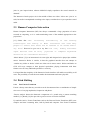
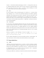
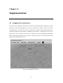
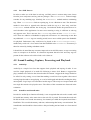
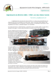
4.1 Graphical User Interface
The main screen of Interactive Rocks is shown below and implemented using the javax.Swing
package. The first task undertaken was to create a simple to use interface, with as few menus
and complexity as possible. The result is an interface where most of the main functions are
available as buttons on the toolbar. In addition to the toolbar, a ColorChooser was used to
change the colour of the hit spots, and a text input box used for changing the maximum
number of hit spots displayed at any one time. The majority of the screen is taken up by the
image of the rock that is to be ‘hit’ .
Figure 5. The Graphical User Interface
17
4.2 Mouse Events
The next stage of implementation was to enable the program to respond to mouse clicks.
Javax provides a MouseEvent listener to achieve this relatively easily. It was decided that hit
spots should be drawn on the screen when the mouse was either clicked (that it a press
followed by release), or dragged. Initially, only a click would create a sound, as dragging was
likely to consume vast amounts of memory.
Following a mouse click, a certain rock sound would be played, dependant on the part of the
rock ‘hit’ . A short algorithm was devised to work out in what sector of the screen the mouse
click was made.
Dimension d = img.getDimension();
w = d.width;
h = d.height;
wConst = w/cols;
hConst = h/rows;
Figure 6. Algorithm to divide screen into sectors
getDimension() returns the size of the current screen in pixels. From this, we make the
necessary type conversions (not shown) and divide the dimensions found by the number of
columns and rows the rock has been divided into (see XML parsing).
Following a mouse click, we use subtract 1 from:
int coOrd = (hOut -1)*rows + wOut;
This returns a segment number, increasing from left to right, top down and triggers the correct
sound to be played. At this stage, playback of a sound already loaded into the SoundList is
made simple by using the AudioClip interface (see 4.5).
4.3 Hit Spots
4.3.1
Displaying
The RockImage class uses standard methods to display the image of the rock as the main
screen background. It also deals with the hit spots by using several ArrayLists.
The addspot method was the first to be devised. It works thus:
•
Check to see if the maximum amount of spots are currently on the screen
•
If not, add the x and y co-ordinates of the hit to separate arrays
•
If no more spots can be drawn, delete the oldest, and add the new co-ordinates to the
array
18
•
Call the repaint() method
The repaint() method calls the original paint() method again. Double buffering was
used for drawing both the rock image, and the hit spots on top so that no flicker appeared
when redrawing.
4.3.2
Recording and Saving
A separate method was devised for recording ‘rock compositions’ . recordSpot(int,
int, int) achieves the same as above, but adds all of the hits to separate arrays where
none are erased. It also records the time of each spot as a long in another ArrayList. Finally, it
records the mouse button pressed. It was decided that by right-clicking, the rock sound would
be looped (rather than just played once), therefore creating an ostinato to build compositions
on.
The writeSpot() method is called when the recording of a rock composition is
terminated. This method writes the details of each hit spot on a single line, each line being
concatenated onto a string. When the Save Composition dialogue is produced, the user is
invited to type a name for the composition. On clicking the save button, the writeSpot()
method is called and all the current spots in memory are exported to the file. A ‘.cmp’
extension is added for file filtering purposes.
4.3.3
Loading and Playback
Loading and playback of hit spots (and their related sounds) were implemented in a similar
way to recording and saving them. The loadSpotData() method is called following the
selection of the file. For each line read, a StringTokenizer is used to obtain each hit spot
attribute. The loadSpot(int, int, long, int) method is called for each line, and
the attributes are added to each ArrayList.
Once each hit spot has been loaded, playback is possible. To maintain the original rhythm of
the hits, the time difference between each spot and its successor is calculated.
Thread.sleep(int) is called to ‘delay’ each hit for the necessary time period.
Java.awt.Robot was considered for playback. The class is aimed for automated
demonstrations and is able to create mouse and keyboard events. It would have been much
better if the mouse were to move to each co-ordinate before creating each spot (as it would
have done when originally recording). However, Robot was not implemented as the mouse
co-ordinates did not always match that of the hit spot. This may have been due to Robot using
the size of the screen, rather than the size of the rock image.
19
4.4 XML ‘Rock’ Files
4.4.1
XML
YQA required the software to be able to play the sounds of many different rocks rather than
just one. XML was considered a highly flexible and well supported format that would enable
the characteristics of an individual rock to be loaded into the software when required. Each
relevant piece of rock data is contained within a tag, in a similar style to HTML. For example,
the name of a picture file might be ‘myHouse.bmp’ . If the tag appeared like so:
<picture>myHouse.bmp</picture>
then an XML parser would be able to extract the file name, and pass it on to another method
in the program (say to display the image). The XMLParser class was able to recognise each
of the relevant tags containing rock data, and use the data contained within each as required.
4.4.2
Rock Files
The characteristics of a rock are contained in a ‘rock file’ , which was given the extension
‘.rock’ . The extension was exploited in a similar way to the ‘rock compositions’ , by using a
file filter to enable only the correct file type for selection.
For a rock’ s details to load correctly into the program, its rock file must contain the following:
•
The number of rows and columns the rock was divided into for recording
•
The file name of the picture of the rock
•
At least (rows * columns) file names of the audio recorded from the rock
The example file shown below is of the rock loaded by default when the program is first
started.
<?xml version="1.0" encoding="utf-8" ?>
<rockInfo>
<rockName>rock1</rockName>
<rows>3</rows>
<cols>3</cols>
<image>default.jpg</image>
<sound>1-1.wav</sound>
<sound>1-2.wav</sound>
..
<sound>3-3.wav</sound>
</rockInfo>
Figure 7. Example of a Rock file
20
4.4.3
Java XML Parsers
In order to make use of the data in each tag, an XML parser is written using some classes
from the javax.xml.parsers and org.xml.sax packages. The startElement method simply
searches for any matching tags. Similarly, the endElement method matches terminating
tags. When startElement finds an opening tag, it sets a Boolean to true. The characters
method is then able to append each character inside the tag to a char array, until the
endElement method matches the closing tag. Get methods enable the parsed data to be
used elsewhere in the application. In most cases returning a string is sufficient as each tag
only appears once. This is not true for a <sound> tag, where at least <cols> * <rows>
exist. These are added to a Hashtable for playback convenience. It is interesting to note that
any additional <sound> tags are actually parsed, but are never called upon in the Hashtable
for playback. Furthermore, they could never be played as the startLoadingSounds()
method only reads cols * rows entries from the Hashtable to the SoundList. No memory is
therefore wasted by loading redundant sounds.
It should also be noted that any erroneous input such as invalid file names, or tags not existing
cause an exception to be thrown. It is therefore important that all of the necessary tags are
present for the software to be able to load a rock’ s data set.
4.5 Sound Loading, Capture, Processing and Playback
4.5.1
AudioClip
AudioClip is a simple Java class that supports basic playback and looping of audio. It was
used for simple playback of an audio file following a mouse click. Button 1 triggered the
play() method to be called on the selected audio file. Button 2 triggered the loop() method to
be called. In early testing, it was found that making several hits close together often caused
existing looped sounds to stop playing, or even be backlogged and therefore making the delay
unacceptable. Logic loops were introduced at this stage to allow only two looped sounds and
two single hit sounds to be played at once. The effects of this constraint are discussed in the
evaluation.
4.5.2
SoundList and SoundLoader
In order for AudioClip to function efficiently, it was recognised that each rock’ s sounds could
be loaded into memory at the same time as the rock file is parsed. This meant that each rock
hit did not load a new sound into memory, but instead just called the required sound from a
HashTable. This saved both memory and time, and meaning that latency was minimised. The
SoundLoader and SoundList classes achieve this pre-loading and are based on a Java tutorial
[21].
21
4.5.3
Audio Capture
Raw audio capture was achieved via a plate microphone. This type of microphone can hang
loosely, or even be attached behind the suspended rock, and is rather more discreet than a
standard microphone.
A while loop provided the capture of audio in the AudioCapture class. The problem with this
method was that it would capture all of the audio it received. This was unnecessary – it only
needed to capture Audio when the rock had been physically struck. The following code
creates a temporary buffer (enough to capture a few seconds of audio). It finds the amplitude
of the signal by calculating the root mean square of the buffer. In order to do this, It must
convert each sample byte into a double [16] and add its square to the overall total. Finally, the
square root of this number divided by the original buffer size gives us the root mean square.
The RMS returned was between 0 and 1. If it was greater than a certain threshold (0.8 by
default), then it was presumed that the rock had been hit (as opposed to receiving background
noise). The resulting audio was saved into a separate array for further processing to take
place.
for (int i = 0; i < tempBuffer.length; i++)
{
double s = (tempBuffer[i] & 0xFF)/ 128.0;
buf[i] = s;
total = total + (s*s);
}
double rms = Math.sqrt(total/size);
Figure 8. Calculating the root mean square of a sample
It was necessary for the application to be able to change this value due to the fact that
different microphones will have different levels of sensitivity. The value could therefore
adjust how hard the rock had to be hit before the microphone captured its sound, which in turn
affects the amount of other noise captured.
4.5.4
Byte arrays and Processing
The sound captured from a microphone (4.5.3) or loaded from file using the AudioInput class
was stored in a byte array. If the sound had originally been sampled at 8 bits, then each byte
represents one sample, and processing can occur.
Three types of processing occurred: A backwards effect, amplification and pitch shifting.
The backwards effect simply reversed the byte array as shown in figure 9. The leftmost and
rightmost bytes are swapped and the boundaries move closer to the centre.
22
Amplification involved converting each byte value to a double, as shown figure 6 when
calculating the amplitude. Each double is then multiplied by a value, converted back to a byte
and placed in a separate array.
Pitch shifting was achieved by only playing back a certain number of bytes from the array.
The X axis of the screen represented the range of pitches available, with the centre being the
original sound. If the rock was hit at the rightmost edge of the screen, only half of the samples
would be played back, shifting the pitch up an octave. In a similar fashion, interpolated values
caused twice the number of samples to be played back for the leftmost edge of the screen,
causing the pitch to be shifted down an octave. Intermediate pitches were reproduced by
scaling the x co-ordinate.
It was unfortunate that pitch shifting was not implemented fully, due to problems with the
sampling rate and playback.
public void reverse(byte[] b) {
int left = 0;
// leftmost element
int right = b.length-1; // rightmost element
while (left < right) {
// exchange the left and right elements
byte temp = b[left];
b[left] = b[right];
b[right] = temp;
// move the bounds toward the centre
left++;
right--;
}
}//endmethod reverse
Figure 9. Reversing a sound
4.5.5
Playback
Playback was achieved by converting the processed audio into a ByteArrayOutputStream
object. A thread was created and the data was passed to a javax.sound.sampled
SourceDataLine object. This is a standard java class which takes audio bytes and passes them
along a DataLine to the default audio output device – in most cases the sound card.
4.5.6
Touchscreen
The touchscreen interface involved a relatively straightforward setting up of hardware. It
should be noted however that some of the original user interface dialogs (such as those
changing the microphone sensitivity or the maximum number of spots) required keyboard
input. These were modified to use the javax JSlider component, allowing full control of the
application with the mouse.
23
Chapter 5
Evaluation
5.1 Introduction
As mentioned in chapter 1, quantitative evaluation of the software would be difficult to
achieve due to the open expressiveness of the software. Much of the evaluation relies on the
thoughts and overall satisfaction of Yorkshire Quarry Arts in terms of ease of use and
requirements met. Some more formal methods of evaluation were eventually devised
however, and are also documented here.
Evaluation criteria were therefore considered for evaluating both the software and the overall
project and are as follows:
•
Ease of Installation
•
Overall ease of use of the software
•
Quality of the user manual
•
Overall fulfilment of YQA requirements
•
Latency between user input and audio output
•
Reaction from children using the software
•
Amount of ‘erroneous spots’ found when composing
•
Are the methods and tools used for the implementation necessarily the best?
The first four criteria concern whether the project has solved the original problem of
designing and implementing the interactive software for Yorkshire Quarry Arts, and their
overall satisfaction with it. The final three concentrate more on the software itself; its
usability, efficiency and flaws are all discussed here. In particular, testing for erroneous spots
gives us a numerical idea of how playable ‘Interactive Rocks’ is as a musical instrument.
24
5.2 Evaluation with Yorkshire Quarry Arts
A formal evaluation and satisfaction survey was conducted with the Yorkshire Quarry Arts
Project Manager. She was presented with a CD with the Interactive Rocks software and a
PDF user manual on, and invited to install and use the software as she wished. Her initial
thoughts on installation were that it was relatively straightforward. Concern was expressed
that the software must be installed in a particular file location, which is not always possible on
a networked workstation.
She found the software easy to use, but had a few minor criticisms and many suggestions for
future work (see chapter 6). She also realised that many of the target users would be young
children, and attempted to evaluate from a child’ s perspective as well.
Her first criticism was that although the colour of the hit spots could be changed, all of the
previous spots displayed would be changed too. This was due to the entire array of spots
being repainted in the new colour. She thought that one child might like to use the software
after another had finished, and that it would be useful to see what the previous child had
‘composed’ by changing the spot colour.
For a similar reason, she also thought that the ability to change the shape of a hit spot would
be of use to the children.
She commented that the latency between making a hit and hearing the sound was minimal;
however there were some problems when several rapid hits were made, as some of the sounds
did not play. In some cases a backlog of sounds built up, and several were played at once a
few seconds later. This was identified as the most significant flaw in the project, and user tests
on this are discussed later in this chapter.
Many of the features were well received. Despite minimal computer literacy, she understood
the short tutorial on how to create a rock data file. She was also pleased with the recording
and playback functions, finding them particularly easy to operate. The live audio capture was
well received, although she was naturally a little disappointed that the pitch shifting had not
been fully implemented in time.
The touch-screen was a success although it was pointed out that this interface could limit
creativity due to the lack of a right click.
Overall, YQA were pleased with the software, and hoped to let a few schools in the area try it
for themselves. The project was successful in that all of the minimum requirements were met
and the solution has been shown to be of sufficient quality.
25
5.3 User Tests
5.3.1
General Impressions
The software was presented to two children of age four and seven. They were told briefly
about how the software worked, and invited to try out its various functions.
Some noticeable trends were picked up, particularly with the ability to change the number of
spots viewable on screen. The subjects were able to create a ‘follow and chase’ scenario when
the maximum number was set to two. Conversely, when the spot number was set to a high
figure, they enjoyed creating a ‘snake’ by dragging the mouse across the rock image.
5.3.2
Erroneous Hit Spots
The main problem with the software was identified fairly early on during the implementation
stage, and also during the YQA evaluation as described above. Here, we describe an
erroneous hit spot as one where the sound was not played back properly, or where is stopped
another sound from completing properly. By calculating the average amount of erroneous
spots made, it was possible to gain a metric to show how much the performer was inhibited by
this behaviour.
Each of the two children was allowed to create a rock composition for one minute. They were
asked to perform another composition using a different rock loaded into the software. A
second rock had to be tested, as the sounds that it produced were much shorter, meaning that
less erroneous spots were likely to occur. As the child performed each composition, two
observers counted the erroneous spots. The average was taken and the results are shown
overleaf.
Rock 1
Child 1
Rock 1
Child 2
Rock 2
Child 1
Rock 2
Child 2
Composition 1
12
14
9
9
Composition 2
14
13
10
10
Average
13
13.5
9.5
9.5
Overall Average
13.25
9.5
Figure 10. Results of the erroneous hits test
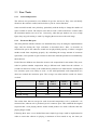
The results show that on average for each 60-second composition, rock 1 produced 13.25
erroneous hits, whereas rock 2 produced just 9.5 erroneous spots. This confirmed the original
suspicion that a rock playing shorter sounds would produce less audio collisions than one
playing longer sounds.
Following these tests, it was decided that some simple logic loops could be implemented in
order to restrict the software to playing a maximum of four sounds at any one time (see
26
section 4.5.1). The tests then repeated with this improvement implemented and the results are
shown below.
Rock 1
Child 1
Rock 1
Child 2
Rock 2
Child 1
Rock 2
Child 2
Composition 1
14
13
8
8
Composition 2
10
9
8
9
Average
12
11
8
8.5
Overall Average
11.5
8.25
Figure 11. Results of the erroneous hits test, after logic restrictions implemented
These results show how limiting the maximum number of sounds that the software can play at
any one time reduces the likelihood of an erroneous spot occurring. For rock 1, the average
number of erroneous hits was reduced by 1.75 to 11.5. The average for rock 2 was reduced by
1.25 to 8.5. This enhances the interaction between the performer and the instrument (i.e. the
user and the software), however does not eliminate the ‘erroneous spots’ problem completely.
5.4 Evaluation of Tools and Implementation Methods
Despite the project meeting all of its minimum requirements, the issue of erroneous spots was
deemed the software’ s biggest problem. The problem still persisted to a lesser degree after
logic loops were implemented. The problem is most probably down to Java consuming a vast
amount of system resources. It could be argued that C++ has superior audio support, and
would have handled multiple sounds better. Java may not have been the best choice of
platform for audio, however YQA required Internet compatibility and Java was more suited to
this.
XML was a good choice for representing a rock’ s data, although a graphical representation
implemented within the main application may have presented a friendlier interface to a user
who wished to create their own rock from scratch.
27
Chapter 6
Conclusion
6.1 Conclusion
In order to solve the initial problem of creating interactive multimedia software for Yorkshire
Quarry Arts, it was necessary to research a variety of different methodologies and tools,
design the software to incorporate YQA’ s requirements, and evaluate and test the software to
determine their satisfaction.
iRocks is a small piece of software implemented in Java, and designed for use by download,
or (with limited functionality) by browser applet. Due to the portability of Java, it was able to
function on a variety of different operating systems. Other platforms were considered for
implementation but rejected due to the lack of portability.
iRocks is able to play back the sounds of various mineral rocks being hit, and enable users to
record and play back their own musical ‘rock compositions’ . A microphone interface allows
the prototype to capture live sound from a rock and process effects on it, such as reversing or
amplification.
The software was evaluated with the project manager of the YQA project in order to
determine satisfaction of the user requirements. The results showed that despite a few minor
problems with the software, it performed well in terms of latency and ease of use. YQA is
satisfied with the functionalities of the iRock prototype and has uploaded the software online
on their project website.
The evaluation highlighted the fact that only so many sounds could be played at any one time.
Any further attempt to ‘hit’ the rock would result in no sound, and often a backlog of spots to
be drawn. Such hit attempts were classified as ‘Erroneous Spots’ . Testing was undertaken to
investigate how serious this problem was in terms of inhibiting the user from composing
music with the program. The software was then modified in an attempt to reduce the number
of erroneous spots. This was successful to some degree, although did not eliminate the
problem.
28
6.2 Future Directions
Frequent meetings with YQA meant that a large number of suggestions for functionality were
made for the software. Unfortunately, many of these had to be discarded due to the lack of
time for researching and implementing the changes. Discussed below are some ideas that may
interest not just a final year computing student, but also a variety of interdisciplinary studies.
The evaluation meeting with the head of YQA yielded many possibilities for future work. She
attempted to view the software from a child’ s point of view. Some of the minor changes
suggested included having many different spot colours and shapes on the screen at any one
time. This would mean that another child could use the software but still see what had been
created before him. Some animation of the spots was also considered a possibility. Rather
than simply disappearing the spots could fade after a certain time. Eliminating erroneous spots
would be a primary concern for the next version of the software.
YQA also discussed the idea of creating a notation for a ‘rock composition’ . It was thought
that children would gain more interactivity from the software by this. The ability to print both
a musical score and the picture of the rock with its hit spots was considered desirable from an
educational point of view. Links could be made between the graphical representation and the
score representation of a ‘rock composition’ . In essence, it could be possible to teach children
some rudimentary aspects of music such as pitch and rhythm using an original representation
rather than following a traditional western score technique. These possible extensions to the
project are direct improvements to the software from YQA’ s point of view, but would also
interest those interested in interactive education.
A geologist or geophysicist may be interested in other possibilities such as the analysis of the
different sounds produced by the rocks. FFT was not implemented in this project, but further
studies may utilise such an algorithm for a variety of uses. The pitch of each section of the
rock could be determined by FFT analysis and links could be made to its organic structure.
For example, the rock might be compressed under several tons of weight. The resultant sound
could then be compared to the original, and any links to the structure of the rock investigated
further.
Finally, a musician or artist may be interested in extensions to the physical interface aspect of
the software (as discussed in Chapter 2). The iRock prototype can be extended to support
multiple rock inputs, with an extensible list of audio effects processing using plug-in
technologies or coded effects. A musician may want to perform music using a variety of rocks
that produce different tone-colours and timbres. iRocks would be a percussion instrument in
its own right. Due to the large amount of data that is likely to be used, MIDI interfaces
discussed in chapter 2 could be one of the ways to optimise the performance of the overall
29
system, with minimal computational requirements. However, for setups equipped with multichannel sound cards and parallel processing, raw audio would provide a high quality and low
latency musical interface.
30
References
[1]
Bennett S, McRobb S & Farmer R, (2001), Object Oriented Systems Analysis and
Design using UML,(2nd Ed.), McGraw Hill
[2]
Deitel, H, and Deitel, P, (2000), C++ How to Program, 3rd Edition, p20, Prentice Hall.
[3]
Eckel, B, (2002), Thinking in Java, 3rd edition, London: Prentice Hall.
[4]
Efford, N, (2002), SO21 Object Oriented Programming Course Notes, pp49-50,
University of Leeds, West Yorkshire, UK.
[5]
Gagne, C, (1993), Interview with Laurie Spiegel, Soundpieces 2:Interviews with
American Composers.
[6]
Gurevich, M.and Muehlen, S, (2001), The Accordiatron: A MIDI Controller,
Proceedings of the 2001 Conference on New Instruments for Musical Expression
(NIME-01).
[7]
Hughes, B and Cotterell, M, (2002), Software Project Management, 3rd edition,
London:McGraw-Hill.
[8]
Hunt, A and Kirk, R, (2003), MidiGrid: Past Present and Future, Proceedings of the
2003 Conference on New Instruments for Musical Expression (NIME-03).
[9]
Johnson, O, (2003), IS21 Object Oriented Analysis and Design Course Notes,
University of Leeds, West Yorkshire, UK.
[10] Jorda, S, (2001), New Musical Interfaces and New Music-Making Paradigms,
Proceedings of the 2001 Conference on New Instruments for Musical Expression
(NIME-01).
[11] Jorda, S, (2002), FMOL:Toward User Friendly, Sophisticated New Instruments,
Computer Music Journal 26(3):23-39.
[12] Kientzle, T, (1998), A Programmer’s Guide to Sound, Ch24, Addison-Wesley.
[13] Miranda, E, (2002), Computer Sound and Design: Synthesis Techniques and
Programming, 2nd edition, Ch.3, Focal Press.
[14] Moore, F, (1988), The Dysfunctions of MIDI, Computer Music Journal 12(1):19-28
31
[15] Object Management Group, Introduction to OMG UML.
URL: http://www.omg.org/gettingstarted/what_is_uml.htm [last accessed 4th February
2004]
[16] Pfisterer, M and Bomers F, (2004), Java Sound Resources: FAQ Audio Programming,
URL: http://www.jsresources.org/faq_audio.html [last accessed 10th April 2004]
[17] Preece, J, Sharp, H, and Rogers, Y, (2002), Interaction Design: Beyond Human
Computer Interaction, New York; Chichester: Wiley.
[18] Roads, C, (1996), The Computer Music Tutorial, Ch21, MIT Press.
[19] Roads, C, (1996), The Computer Music Tutorial, Appendix A, MIT Press.
[20] Sun Microsystems, (2003), JavaTM 2 Platform, Standard Edition, v 1.4.2 API
Specification,
URL: http://java.sun.com/j2se/1.4.2/docs/api/ [last accessed 08th April 2003]
[21] Sun Microsystems, (2004), The Java Tutorial:Playing Sounds.
URL: http://java.sun.com/docs/books/tutorial/sound/playing.html [last accessed 12
April 2004]
[22] Verplank, B, Sapp, C, and Mathews, M, (2001), A Course on Controllers, Proceedings
of the 2001 Conference on New Instruments for Musical Expression (NIME-01).
[23] Wilkerson, C, Ng, C, and Serafin, S, (2002), The Mutha Rubboard Controller,
Proceedings of the 2002 Conference on New Instruments for Musical Expression
(NIME-02).
32
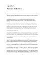
Appendix A
Personal Reflections
This section describes whether the project met its objectives, and gives so of my own personal
reflections on the experience.
I feel that all of the objectives of the project have been successfully achieved. It was a
rewarding experience to see that Yorkshire Quarry Arts were pleased with the software
produced.
I think that this project has emphasised the importance of careful project planning and time
management. This project was somewhat open ended as new requirements and functionality
were discussed with YQA throughout. I was disappointed that some of the audio processing
effects had to be discarded due to a lack of time. I think that with a little more time, pitch
shifting could have been achieved by dragging the mouse (rather than just clicking) thus
creating a glissando (sliding) effect.
The mid project report highlighted that the project was quite ambitious for 20 credits of study.
Despite this, I have fully enjoyed the experience of designing and creating the software, and
being involved with the YQA project team. The involvement of YQA kept my mind focussed
on the schedule, and despite one or two deadlines being a day late, the majority of work was
completed on time.
My suggestion to future students would be to consider the programming environment
carefully. I chose Java due to its compatibility with web browsers, but also because I found it
the most comfortable language to program in. Java support for sound is somewhat limited,
and future students may struggle to make any further progress than this project has for a 20credit study. It would be interesting to see what directions a 40-credit project might take with
‘Interactive Rocks’ .
I would also advise future students to investigate using FFT. I made a very brief attempt at
FFT, but when this was combined with the graphics and sound, a simple rock hit became
intolerably slow to process. FFT would allow a future project to concentrate more on audio
manipulation, thus creating more effects. It would also mean that the sound would not have to
be sampled at a set rate like the byte manipulation method required in this project.
33
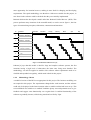
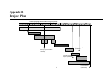
Appendix B
Project Plan
October
Chart Displaying time allocation for Fyproj Project
November
December
January
Febuary
March
April
Aim/req (24/10/03)
Progress meeting
(19/03/04)
Mid proj report deadline
12/12/03)
contents and draft
chapter (05/03/04)
34
Final Deadline
(28/04/04)
Appendix C
User Manual
12345673894
7
45
84
Version 2.2
Rob Davison
University of Leeds
April 2004
35
12345673894
7
45
84
Version 2.2
Installation
1. You may need to install the Java Runtime Environment on your computer.
Windows users should click on the ‘j2re Windows.exe’ icon and follow the on
screen instructions.
Linux Users should follow the instructions given by Sun Microsystems at
http://java.com/en/download/help/linux_install.jsp#self-extracting
2. Copy the irock folder to the directory
C:\Program Files\irock
on your hard drive. (The program will not work, if installed anywhere else!)
3. Windows users may copy the ‘iRocks’ shortcut to their desktop or start menu for
convenience.
Using iRocks 2.2
1. Make sure your pc speakers are connected and switched on.
2. Windows users: click on the ‘iRocks’ icon to start the program
36
Linux users change directory to
C:\Program Files\irock
And type: java YQA
Hear the Rock
•
•
Left click on different areas of the screen to hear how the rock sounds.
If you right click instead, the sound is repeated over and over.
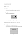
Change the Spot Colour
1. Click on the colour changer as shown:
2. A colour change dialog box will appear. Select your desired colour from the
palette, and click ‘OK’.
Alternatively, you can select ‘Change Colour’ from the ‘Options’ menu.
Change the Maximum number of spots on screen
1. In the Options menu, select ‘Change Spot Number’.
2. You will see a box as shown below. Use the slider to select the number
required.
37
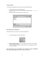
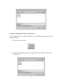
Change the Rock
You are able to see and hear other rocks, from Yorkshire Quarry Arts.
1. In the Options menu, select ‘Change Rock’.
2. Navigate to the directory where the program is installed (that is, C:\Program
Files\irock).
3. Select a rock file. These usually end in .rock or .xml.
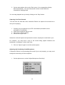
Recording a Rock ‘Composition’
Interactive Rocks can record you own musical compositions.
1. To start recording, click on the ‘Rec’ button.
2. Use the mouse to create your musical masterpiece. When you are finished,
click on the ‘Save’ button.
3. A ‘Save’ dialog box will appear. Type a name for your composition and click
on the ‘Save’ button.
N.b. Do NOT click on the stop button. This will clear all of your composition
from memory! Remember to click on the ‘Save’ button first!
38
Loading or Playing back a Rock ‘Composition’
In order to play back your musical creations, you must load the composition file into
Interactive Rocks.
1. Click on the ‘Load’ button.
2. Select the composition you wish to play back from the list given. Click on the
‘Load’ button.
39
3. On the main toolbar, click on the ‘Play’ button. Your composition will play
back automatically. You can still play the rock as normal whilst the
composition is playing back.
You can stop playback at any time by clicking on the ‘Stop’ button.
Capturing Live Rock Sounds
‘You can have fun with real rocks: Interactive Rocks’ can capture live sound from a
rock you are playing.
1. Connect your microphone to your PC’s soundcard (and switch on the
microphone if necessary).
2. Place the microphone near the rock.
3. Click on the ‘Capture’ button.
4. Hit the rock as you wish.
Interactive rocks will capture and process the sound, and play the result back to you.
For instance, you may hear a loop of the sound being played forwards and
backwards, increasing in volume each time.
5. Click on ‘Capture’ again to end the audio capture.
Adjusting the Sensitivity of the Microphone
If Interactive Rocks is not processing the sound of your rock properly, you may need
to adjust the sensitivity of the microphone.
1. On the options menu, select ‘Adjust Microphone Sensitivity’
40
2. Move the slider and hit the rock until capture is satisfactory
Exiting the Program
Select ‘Exit’ from the File menu, or click on the close button in the top right of the
window.
Customising Interactive Rocks (Advanced Users only)
Advanced users can edit rock files to play back their own sounds, and display their
own images.
You should open up an existing rock file in a plain text editor such as notepad or vim.
An example rock file is shown overleaf:
41
<?xml version="1.0" encoding="utf-8" ?>
<rockInfo>
<rows>3</rows>
<cols>3</cols>
<image>default.jpg</image>
<sound>1-1.wav</sound>
<sound>1-2.wav</sound>
<sound>1-3.wav</sound>
<sound>2-1.wav</sound>
<sound>2-2.wav</sound>
<sound>2-3.wav</sound>
<sound>3-1.wav</sound>
<sound>3-2.wav</sound>
<sound>3-3.wav</sound>
</rockInfo>
Edit the file as follows:
1. Imagine the screen to be divided into a matrix. If you have 12 different
sounds, this would be 4 columns and 3 rows (or vice versa). Insert these
numbers between the <rows> and <cols> tags as desired.
2. Insert the filename of the image you wish to appear on the screen between
the <image> tag.
3. You MUST have at least <rows> * <cols> amount of <sound> tags. Insert the
name of each sound file between these tags. The sounds will be assigned to
the screen from left to right, top to bottom as they are read from the file.
4. Save your rock file using a different filename. Do NOT overwrite
‘default.rock’
42