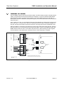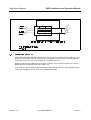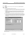
1
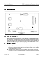
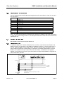
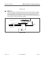
Please Keep Manual with the Device!
Part # MAN-ZNDC-01
Revision 1.0
04-02-2002
ZETA ALARM SYSTEMS
72-78 Morfa Road
Swansea. SA1 2EN
U.K.
http://www.zeta-alarms.co.uk
[email protected]
Zeta Alarm Systems.
ZNDC Installation and Operation Manual
Table of Contents
1.
Introduction To The Networked Digital Communicator ..............................................1
1.1
1.2
1.3
1.4
2.
Specifications .....................................................................................................................3
2.1
2.2
2.3
2.4
2.5
2.6
2.7
2.8
3.
Electrical Specifications .....................................................................................................3
Wiring Specifications 3
2.2.1 Electrical Wiring ....................................................................................................3
2.2.2 Telephone Wiring ..................................................................................................3
Environmental Specifications ............................................................................................3
Indicator Lights (LEDs) ...................................................................................................... 4
Telephone Requirements ...................................................................................................4
Mechanical ........................................................................................................................5
Handy Accessories ............................................................................................................5
Listings ..............................................................................................................................5
2.8.1 UL ......................................................................................................................... 5
2.8.2 FCC ......................................................................................................................5
Installation .........................................................................................................................6
3.1
3.2
3.3
3.4
3.5
3.6
4.
Features ............................................................................................................................1
How To Contact Zeta Alarm Systems .................................................................................1
What You Get: ...................................................................................................................2
Compatible UL Fire Listed Receivers ................................................................................2
Mounting Requirements ....................................................................................................6
3.1.1 Bare Board Installation .........................................................................................6
3.1.2 ZNDC Enclosure Installation .................................................................................7
Grounding Instructions ...................................................................................................... 8
Wiring ................................................................................................................................ 8
3.3.1 Wiring Precautions................................................................................................ 8
3.3.2 Connecting Power and Network ...........................................................................9
Network Installation ...........................................................................................................9
3.4.1 Classic 2000 Mk II ................................................................................................ 9
3.4.2 Sigma Mk II......................................................................................................... 10
Connecting Phone Lines ................................................................................................. 11
Connecting to the PC ...................................................................................................... 12
Programming ...................................................................................................................13
4.1
4.2
Revision 1.0
At the Panel .....................................................................................................................13
4.1.1 Classic 2000 Mk II ..............................................................................................13
4.1.2 Sigma Mk II .........................................................................................................13
At the PC ......................................................................................................................... 14
4.2.1 ZNDC Data .........................................................................................................14
4.2.2 Account Data ...................................................................................................... 15
4.2.3 Communications .................................................................................................16
Part # MAN-ZNDC-01
Page i
Zeta Alarm Systems.
5.
Operation .........................................................................................................................18
5.1
5.2
5.3
5.4
5.5
6.
“Comm Test” Switch ........................................................................................................18
Ademco Contact ID Protocol Notes ................................................................................. 18
5.2.1 Handshake ..........................................................................................................18
5.2.2 Event Format ...................................................................................................... 18
5.2.3 Kissoff Tone ........................................................................................................18
Phone Line Usage ........................................................................................................... 18
Phone Line Supervision ...................................................................................................18
PC Programming Software Notes ....................................................................................19
Troubleshooting ...............................................................................................................20
6.1
6.2
7.
ZNDC Installation and Operation Manual
Diagnostic Table ...............................................................................................................20
ZNDC-Related Panel Events ...........................................................................................22
6.2.1 Classic 2000 Mk II ..............................................................................................22
6.2.2 Sigma Mk II .........................................................................................................22
Reporting .........................................................................................................................23
Appendix A: Mounting Template ..................................................................................24
Revision 1.0
Part # MAN-ZNDC-01
Page ii
Zeta Alarm Systems.
ZNDC Installation and Operation Manual
1. Introduction To The
Networked Digital Communicator
The Networked Digital Communicator (ZNDC) is a UL listed dual-line dialer, that allows a Zeta
Alarm Systems Sigma Mk II or Classic 2000 Mk II fire alarm control panel to report events to a central monitoring station, over the public phone system. The ZNDC supports the Contact ID reporting
protocol for reporting the type and location of events. The ZNDC requires the use of two phone
lines.
1.1
Features
1.2
Compatible with the industry-standard Ademco Contact ID reporting protocol.
Built-in dual phone line-seizure circuit.
Programmable for Tone or Pulse dialing.
Dual phone line monitor circuits.
Transient voltage protection of phone lines.
Light-emitting diodes (LEDs), visible from front of enclosure, indicating: Alive (Green); ZNDC
Trouble (Yellow); Line 1 Fault (Yellow); Line 2 Fault (Yellow); Line 1 In Use (Green); Line 2 In
Use (Green).
Easy programming using PC Programming Software
Fuseless design, 24 VDC.
Electrically erasable read-only memory (EEPROM) for nonvolatile storage of all programmable option data. Eliminates the need to reprogram the communicator if power is lost.
Built-in watchdog circuit that monitors the operation of the ZNDC.
Compatibility with many Underwriters Laboratories (UL) Fire Listed receivers (see Section 1.4
for list).
Model 2996 provided as a bare board for mounting inside Zeta Alarm Systems’ Sigma Mk II or
Classic 2000 Mk II enclosures.
Model 2997 housed in a 9.25" x 7.18" x 2" metal enclosure.
Compatible with Zeta Alarm Systems Sigma Mk II or Classic 2000 Mk II FACPs.
When used with Classic 2000 Mk II, reports event address for point alarms and troubles.
Optional diagnostic speaker.
May be mounted up to 8000 feet from the FACP. Note: See Section 2.2 for further details.
Comm Test button for generating a manual test report.
Selective reporting.
How To Contact Zeta Alarm Systems™
World Wide Web:
Internet E-Mail:
Phone:
FAX:
Snail Mail:
Revision 1.0
http://www.zeta-alarms.co.uk
[email protected]
+44 1792 455175 or +44 1792 470394
+44 1792 455176
Zeta Alarm Systems
72-78 Morfa Rd
Swansea, U.K. SA1 2EN
Part # MAN-ZNDC-01
Page 1
Zeta Alarm Systems.
1.3
ZNDC Installation and Operation Manual
What You Get:
Networked Digital Communicator
Hardware Kit
-
Manual
-
2 Ground Nuts
-
Cabinet (standard only with model 2997)
-
4 plastic stand-offs (standard only with model 2996)
-
2 Keys
Optional Items:
Programming Kit
-
Manual
-
ZNDC Programmer Software
-
PCI cable
-
Diagnostic Speaker
RJ45 Kit
-
10 8-pin RJ45 connectors
-
RJ45 crimp tool
Note: Older revisions of panel software do not support the ZNDC. The Classic 2000 Mk II
panel must have at least v1.4 to support the ZNDC, and the Sigma Mk II must have at least
v3.1. Verify the version at the panel; then check with Zeta Alarm Systems for the latest revision.
1.4
Compatible UL Fire Listed Receivers
RECEIVER
MODEL
Sur-Gard
MLR2-DG
FBII
CP220
Radionics
6600
Osborne Hoffman
OH-2000
Ademco
685
Silent Knight
9800
Revision 1.0
Part # MAN-ZNDC-01
Page 2
Zeta Alarm Systems.
ZNDC Installation and Operation Manual
2. Specifications
2.1
Electrical Specifications
All circuits are supervised and Power Limited.* Zeta Alarm Systems requires that the ZNDC be
mounted inside one of our UL listed enclosures, and be powered from an IPB-3 (Inline Power
Booster), Sigma Mk II or Classic 2000 Mk II continuous 24VDC output.
Power Requirements:
Voltage:
Current:
24VDC (22-28VDC)
Nominal
Max
56mA
76mA
Network: RS-485, 9600 baud (Sigma Mk II) or 19200 baud (Classic 2000 Mk II)
*Note: Phone lines are supervised but not power limited.
2.2
Wiring Specifications
2.2.1
Electrical Wiring
Please adhere to the following guidelines for wiring the ZNDC:
Recommended Wire Type: 14 – 22 AWG shielded, twisted-pair
Maximum Cable Length: 8000 ft. (@16 AWG) ***See Note***
Maximum Total Cable Resistance: 50Ω. ***See Note***
Maximum Cable Capacitance: 0.3µF. ***See Note***
Wiring should not cross or rest on the circuit board.
Note: The above cable length is actually the maximum length for the RS485 Network coming off the Classic 2000 Mk II or Sigma Mk II Control Panels, and thus would apply to the
ZNDC only if it is the last device on the network, and no other devices were attached.
The most important thing to remember when wiring a device is to make sure that the cable
does not exceed maximum capacitance and resistance. The levels of capacitance and
resistance can be affected by the gauge and the quality of the cable being used. Cable will
be specified by the manufacturer according to capacitance and resistance per foot. To
accurately figure cable length, divide the Maximum Capacitance by the cable’s Capacitance-Per-Foot. This will give you the maximum length of cable you can use before you
exceed the Maximum Capacitance. (Likewise with resistance.)
2.2.2
Telephone Wiring
Use 4-pair, straight through, standard telephone cabling. RJ45 connectors are supplied in the
installation kit. See section 3.5 for wiring diagram.
2.3
Environmental Specifications
To prevent water damage, please observe the following restrictions when mounting the ZNDC:
Do not mount directly on exterior walls, especially masonry walls, due to condensation.
Do not mount directly on exterior walls below grade due to condensation.
Indoor use only.
Protect from plumbing leaks.
Revision 1.0
Part # MAN-ZNDC-01
Page 3
Zeta Alarm Systems.
2.4
ZNDC Installation and Operation Manual
Protect from splash caused by sprinkler system inspection ports.
Do not mount in areas with humidity-generating equipment (ex. dryers, production
machinery, etc.).
Operating temperature range is: 32° to 120° F (0° to 49° C)
10% to 85% non-condensing humidity at 86° F (30° C)
Non-corrosive environment.
Indicator Lights (LEDs)
The ZNDC provides the following LEDs:
LED
2.5
Function
Description
LED1
ALIVE
Blinks once a second while the ZNDC is running (think of it as
a heartbeat)
LED2
TROUBLE
On if any trouble conditions are present on the ZNDC
LED3
LINE 1 FAULT
On when a fault on phone line #1 has been detected
LED4
LINE 2 FAULT
On when a fault on phone line #2 has been detected
LED5
LINE 1 IN USE
On when phone line #1 is in use
LED6
LINE 2 IN USE
On when phone line #2 is in use
Telephone Requirements
1. If requested by the telephone company, the following information must be provided before
connecting this device to the phone lines
A. Distributer: Zeta Alarm Systems.
B. Model Number: 2996/2997
C. FCC Registration Number: 4T2USA-34005-AL-T
Ringer equivalence: 0.1B
2. This device may not be directly connected to coin telephone, ground start, or party line services.
3. This device may not be adjusted or repaired in the field. In case of trouble with the device,
notify the installing company or return to:
Zeta Alarm Systems.
72-78 Morfa Rd
Swansea
U.K.
+44 1792 455175
4. If the ZNDC causes harm to the telephone network, the telephone company will notify the user
in advance that temporary discontinuance of service may be required. If advance notice is not
practical, the telephone company will notify the user as soon as possible. The user has the
right to file a complaint with the Federal Communications Commission (FCC) if he or she
believes it is necessary.
5. The telephone company may make changes in its facilities, equipment, operations, or
procedures that could affect the operation of the equipment. If this happens, the telephone
company will provide advance notice so that you can make the necessary modifications to
maintain uninterrupted service.
Revision 1.0
Part # MAN-ZNDC-01
Page 4
Zeta Alarm Systems.
2.6
ZNDC Installation and Operation Manual
Mechanical
Board Dimensions: 6" x 4" x 0.875"
Board Weight: 0.3125 lbs. (5 oz.)
Box Dimensions: 9.25 " x 7.18" x 2"
Box Color: Red
2.7
Handy Accessories
The Installation kit includes a small diagnostic speaker. The speaker plugs into J6 on the ZNDC
board. It will be used for audio verification of line seizure, dialing, and communications with central
station receivers. See Illustration 3.0A.
2.8
Listings
2.8.1
UL
The ZNDC is listed with Underwriters Laboratories and complies with UL 864 / NFPA 72. All UL
installations must comply with the requirements described below:
2.8.2
FCC
This equipment has been tested and found to comply with the limits for a Class A digital device,
pursuant to Part 15 of the FCC Rules. These limits are designed to provide reasonable protection
against harmful interference when the equipment is operated in a commercial environment. This
equipment generates, uses, and can radiate radio frequency energy and, if not installed and used
in accordance with the instruction manual, may cause harmful interference to radio communications. Operation of this equipment in a residential area is likely to cause harmful interference in
which case the user will be required to correct the interference at his own expense.
WARNING:
This equipment generates and uses radio frequency energy. If it is not installed and used as dictated
in this manual, it may interfere with radio communications. Also, if the user makes any changes or
modifications to the equipment not expressly approved by Zeta Alarm Systems., he or she could void
the user’s authority to operate the equipment.
Revision 1.0
Part # MAN-ZNDC-01
Page 5
Zeta Alarm Systems.
3.
ZNDC Installation and Operation Manual
Installation
Figure No. 3.0A
3.1 Mounting Requirements
Zeta Alarm Systems requires that the ZNDC be mounted inside one of our UL listed enclosures,
and be powered from an IPB-3 (Inline Power Booster), Sigma Mk II or Classic 2000 Mk II continuous 24VDC output. The ZNDC should be mounted using the supplied components. The four plastic standoffs snap into the ZNDC board, and the four screws are used to secure the standoffs to a
flat surface. The ZNDC board requires four mounting holes (0.3125" diameter) placed in a rectangle, with 5.30" horizontal spacing, and 2.95" vertical spacing.
3.1.1 Bare Board Installation
All mounting accessories are included in Installation Kit.
If you wish to mount the ZNDC inside the panel cabinet, Zeta Alarm Systems requires that you
place the panel batteries in a companion battery cabinet next to the panel cabinet, freeing the
back wall of the cabinet to mount the ZNDC. Use the template in Appendix A of this manual to
accurately drill the holes for the board.
After drilling the holes, attach the stand-offs to the cabinet. Position the board over the standoffs so that the four holes in the board match up with the standoffs. Snap board onto standoffs.
Revision 1.0
Part # MAN-ZNDC-01
Page 6
Zeta Alarm Systems.
ZNDC Installation and Operation Manual
BARE BOARD INSTALLATION
ILLUS. 3.1A
PLASTIC STANDOFFS
SCREWS
NOTE: USE DRILL TEMPLATE IN APPX. A.
Figure No. 3.1A
3.1.2 ZNDC Enclosure Installation
All mounting accessories included in the Installation Kit.
Mount ZNDC enclosure to the wall so that the lock is on the right side. Open cabinet and position board over standoffs so that the LEDs are at the top. Snap board into place.
ENCLOSURE INSTALLATION
ILLUS 3.1B
Figure 3.1B
Revision 1.0
Part # MAN-ZNDC-01
Page 7
Zeta Alarm Systems.
ZNDC Installation and Operation Manual
3.2 Grounding Instructions
For bare board installation, ground board by attaching green grounding wire from J1 on board
to earth ground.
For ZNDC enclosure installation, ground board by attaching green grounding wire from J1 on
board to threaded stud in lower left-hand corner of enclosure. Secure with nut. Connect enclosure to earth ground. See Illustration 3.3A.
3.3 Wiring
3.3.1 Wiring Precautions
Maintain ¼" spacing between high and low voltage circuits and power limited and non-power
limited circuits as per the National Electrical Code Article 780.
Induced noise (transfer of electrical energy from one wire to another) can interfere with telephone
communication or even cause false alarms. To avoid induced noise, follow these guidelines:
Do not pull wires from different groups through the same conduit. If you must run them
together, do so for as short a distance as possible or use shielded cable. Connect the shield to
earth ground at the panel only.
High frequency noise, such as that produced by the inductive reactance of a speaker or bell,
can also be reduced by running the wire through ferrite shield beads or by wrapping it around
a ferrite torroid.
Route the wiring around the inside parameter of the enclosure. It should not cross the circuit
board where it could induce noise into the sensitive microelectronics or pick up unwanted RF
noise from the high speed circuits.
WIRE ROUTING DIAGRAM - NDC IN ENCLOSURE
ILLUS. 3.3A
LINE 1
GND
24V
LINE 2
_
+
TO NETWORK
CONNECTION AT FACP
J1
TO RJ31X CONNECTORS
Figure 3.3A
Revision 1.0
Part # MAN-ZNDC-01
Page 8
Zeta Alarm Systems.
ZNDC Installation and Operation Manual
3.3.2 Connecting Power and Network
Connect 24VDC power and RS-485 network signals from the control panel to TB1. The pin-out of
the connector is:
Pin
Function
1
RS-485 + In
2
RS-485 – In
3
RS-485 Shield In
4
RS-485 + Out
5
RS-485 – Out
6
RS-485 Shield Out
7
24VDC Out
8
Ground Out
9
24VDC In
10
Ground In
Pins 1, 2, 9, and 10 and required; the remainder are optional. In addition to the power connections
on TB1, also connect earth ground to J1, the metal pin located in the lower left corner of the board
(see section 3.2).
3.4 Network Installation
Note: ZNDC is hard-coded at network address 10.
3.4.1 Classic 2000 Mk II
To install the ZNDC with a Classic 2000 Mk II FACP, connect a cable between the RS485+ and
RS485- terminals on the ZNDC to the RS485+ and RS485- terminals on the panel (terminals 17
and 18). Power the ZNDC from a 24VDC source, either the network power connections on the
panel, a NAC configured as a power supply on the panel, or an IPB-3 power booster. Once the
ZNDC is connected, power up the panel, then scan the network. The ZNDC should appear at
address 10. If it does not, then check your connections and verify that the ZNDC is configured for
Classic 2000 Mk II operation.
+
ZRM PORT
17
-
+
18
19
20
-
+24V
21
22
23
GND +24V
24
25
GND
26
10
S3OOO
9
GND
8
+24V
7
GND
TO OTHER
NETWORK
DEVICES
NDC
Revision 1.0
1
+
2
3
+
4
5
6
+24V
NETWORK WIRING DIAGRAM - S3000
ILLUS. 3.4A
Part # MAN-ZNDC-01
Page 9
Zeta Alarm Systems.
ZNDC Installation and Operation Manual
Figure No. 3.4A
3.4.2 Sigma Mk II
To install the ZNDC with a Sigma Mk II FACP, connect a cable between the RS485+ and RS485terminals on the ZNDC to the RS485+ and RS485- terminals on the panel (using either a NIM or
SCP1). Power the ZNDC from a 24VDC source, either one of the AUX24 outputs on the panel, or
an IPB-3 power booster. Once the ZNDC is connected, power up the panel, then scan the network. The ZNDC should appear at address 10. If it does not, then check your connections and verify that the ZNDC is configured for Sigma Mk II operation.
+
NETWORK WIRING DIAGRAM - S1000
ILLUS. 3.4B
1
+
2
3
4
+24V
5
6
7
GND +24V
8
9
GND
10
NDC
- +
2
3
4
5
6
-
7
S1000
+
8
9 10
11 12
13 14
15 16
17 18
TO OTHER
NETWORK
DEVICES
19 20
TO 24VDC*
DEVICE
*NOTE: EITHER 7&8 OR 5&6
ARE ACCEPTABLE TO USE
FOR 24V OUT.
TB1
+
SCP1
Figure No. 3.4B
Revision 1.0
Part # MAN-ZNDC-01
Page 10
Zeta Alarm Systems.
3.5
ZNDC Installation and Operation Manual
Connecting Phone Lines
Connect ZNDC to phone lines using two RJ45 cables. The RJ45 cables should be standard 8-wire
cables. Connectors and crimps are included in the RJ45 Kit, or may be obtained independently.
See Illustration 4.5B for connector wiring diagram. The RJ45 cables will plug into the wall via
RJ31X jacks, which are installed by the phone company. There will need to be one RJ31X jack for
each phone line.
Pins 1 and 8 (“R1” and “T1”) of the RJ31X jack connect to Network (or, House) phone lines. Pins 4
and 5 (“R” and “T”) connect to the Telco (or, external) phone lines. When nothing is plugged into
the jack, shorting bars inside the jack will connect the incoming Telco lines to the Network Lines.
When the ZNDC is connected, the RJ45 plug will open the shorting bars inside the jack, allowing
the phone lines to run from the Telco lines, through the ZNDC, and out to the Network. When the
ZNDC needs to send an event, it will “seize” the phone line by disconnecting the Telco signals
from the Network. It will restore the connection when the event reporting is complete.
RJ31X JACK 1
To
N etw ork
(H ouse
Lines)
T1
To
TELC O
Lines
(Outside
W iring)
T
(Primary Lines)
8
NDC
7
6
5
4
3
2
1
R1
R
Line 1
RJ45
RJ31X JACK 2
To
N etwork
(H ouse
Lines)
T1
To
TELC O
Lines
(O utside
Wiring)
T
R1
R
Modular Female
Connectors
MALE PLUG
CONNECTORS
8
7
6
5
4
3
2
1
Line 2
J1
(Secondary Lines)
Note:
RJ31X Jacks provided by telephone company. Shorting
bars inside RJ31X jacks rem ove during male plug insertion.
WiringWiring
Phone
Jacks
Phone
Jacks
Illus. 3.5A
Illus. 3.5A
Figure No. 3.5A
Revision 1.0
Part # MAN-ZNDC-01
Page 11
Zeta Alarm Systems.
ZNDC Installation and Operation Manual
Figure No. 3.5B
3.6
Connecting to the PC
A PCI cable is included with the Installation kit. At one end of the rainbow ribbon cable is a 10-pin,
female connector that hooks into the PCI port on the ZNDC. The other end is a female DB9 connector that connects to one of the COM ports on the back of the PC.
Most PCs will have two COM ports on the back, marked 1 and 2. Some PCs have more, but the
ZNDC has been configured to use only COM 1 or 2.
If you have to use an extension cable between the PCI cable and the PC, use a straight-through,
male to female DB9 connector. Do not use a Null Modem cable.
Revision 1.0
Part # MAN-ZNDC-01
Page 12
Zeta Alarm Systems.
ZNDC Installation and Operation Manual
4. Programming
4.1
At the Panel
4.1.1 Classic 2000 Mk II
Scan ZNDC into the panel.
First, go to the Programming menu by hitting the PROG key.
Choose option 3, NETWORK.
Choose option 1, SCAN. Once the ZNDC is scanned in, you’re ready to go!
4.1.2 Sigma Mk II
Scan ZNDC into the panel.
Start by holding the “Select” key and the “Enter” key down at the same time.
Hit the “Select” key until the screen reads “nEt.”
Hit “Enter” to scan the network. Once the ZNDC is scanned in, you’re ready to go!
Revision 1.0
Part # MAN-ZNDC-01
Page 13
Zeta Alarm Systems.
4.2
ZNDC Installation and Operation Manual
At the PC
The ZNDC is programmed using the PC-based configuration program, ZNDC Programmer.
4.2.1 ZNDC Data
The “General Configuration” panel allows you to select:
Seconds Between Dial Attempts: If the ZNDC must make more than one attempt to reach the
central station, this parameter controls how long the ZNDC waits before trying again. Default:
5 seconds.
Maximum Handshake Time: This is the maximum amount of time the ZNDC will wait for a
handshake to be acknowledged by the Central Station. Note: generally, there is no need to
change this setting from the default. However, you might shorten it for test purposes only.
Default: 45 seconds.
Host Panel: Select either Classic 2000 Mk II or Sigma Mk II. Default: Classic 2000 Mk II.
Periodic Test Report Time: This section is used in a Sigma Mk II application.* The Sigma Mk II
panel will send out a periodic test report first at startup, and then at an appointed time later in
the day, and each following day at the same time. With this feature, the time that the periodic
test report is sent out is set at the ZNDC. Note: the time is in 24-hour mode, so 11:00 p.m.
would be 23:00.
* When the ZNDC is used with the Classic 2000 Mk II panel, the Periodic Test Report is sent when the panel
performs a self-test. The default time for the self-test is midnight; refer to the Classic 2000 Mk IIUser
Manual for further details.
Revision 1.0
Part # MAN-ZNDC-01
Page 14
Zeta Alarm Systems.
ZNDC Installation and Operation Manual
4.2.2 Account Data
The ZNDC offers selective reporting. In other words, you may set the ZNDC to report events to
more than one central station. In addition, you may choose which events are reported to which station. In order to communicate with a central station, you must program the ZNDC with the:
Account Number: This must be a four-digit number (0000-9999), and will be provided by the
central station.
Primary Phone Number: This is the number of the central station. You may use up to 32 characters. The number may include a “,” (comma) to delay for two seconds. This is useful if, for
example, you need to route the call through a PBX system. If your phone line supports the
“call waiting” feature, you should disable it by prepending a “*70” for tone dialing, or a “1170”
for pulse dialing.
Secondary Phone Number: This is a secondary number at the same central station, and will
be used as back up in case the primary phone number is somehow disabled.
Reporting Format: Only “Contact ID” is offered.
Revision 1.0
Part # MAN-ZNDC-01
Page 15
Zeta Alarm Systems.
ZNDC Installation and Operation Manual
4.2.3 Communications
The Communications tab provides the communication forum between the ZNDC and ZNDC Programmer. Communications may be viewed in one of two modes: Program or Debug.
Program Mode has the following features:
Read From ZNDC: allows you to import previously programmed configuration and account
data from the ZNDC to the ZNDC Programmer. This is especially useful if ZNDC Programmer
is closed and re-opened, resetting configuration data to defaults and clearing all account data.
Write To ZNDC: allows you to transfer configuration and account data from ZNDC Programmer to the ZNDC.
Online: shows whether or not you are "online," or connected, to the ZNDC. Once you have
gone online, it will also display the ZNDC’s firmware version and release date next to this box.
COMX: indicates the communication port on the PC to which the ZNDC is connected. The
ZNDC may be hooked to either COM1 or COM2. This option may be changed at the Programmer by clicking just below "Online," directly on top of the "COMX." The communications
between the PC and ZNDC requires a PCI cable, connected between the COM port on the
computer and the "PCI" port on the ZNDC (installed with the cable flowing toward the outside
edge of the PCB).
"TX Data" and "RX Data": show the messages as sent to and received from the ZNDC.
Revision 1.0
Part # MAN-ZNDC-01
Page 16
Zeta Alarm Systems.
ZNDC Installation and Operation Manual
Debug mode is basically a running commentary on what is happening at the ZNDC. It reports dialing attempts, as well as panel events. To interpret the event codes, see Section 6.2.
Revision 1.0
Part # MAN-ZNDC-01
Page 17
Zeta Alarm Systems.
ZNDC Installation and Operation Manual
5. Operation
5.1
“Comm Test” Switch
The “Comm Test” switch provides a way to manually test the operation of the ZNDC. When the
switch is pressed, the unit will attempt to send a “Manual Test Report” event to the central station
(event code 601). Test reports (whether manual or periodic) are sent on alternating phone lines.
That is, if one test report is sent via line #1, the next will be sent via line #2.
5.2
Ademco Contact ID Protocol Notes
5.2.1. Handshake
The Contact ID protocol expects a dual-tone handshake (1400Hz for 100ms, 0Hz for 100ms, and
2300Hz for 100ms). If the ZNDC does not receive a handshake within 8 seconds after the last digit
of the phone number has been dialed, it will hang up and swap lines.
5.2.2 Event Format
An event is sent using DTMF tones (100ms per digit: 50ms on, 50ms off) in the following format:
ACCT MT QXYZ GG CCC S
ACCT = 4 digit account number
MT
= message type (always “18”)
Q
= event qualifier (“1” = new event, “3” = restoral, “6” = previous event)
XYZ = event code
GG
= group number (Classic 2000 Mk II uses this for the “loop number”)
CCC = zone or sensor number (Classic 2000 Mk II uses this as the device address within the
loop specified in the “group” field)
S
= checksum ((sum of all message digits + S) MOD 15 = 0)
5.2.3 Kissoff Tone
The ZNDC expects a kissoff tone of 1400Hz, lasting at least 400ms, followed by 250ms of silence.
If the ZNDC doesn’t detect the kissoff tone, it will resend the event. Events will continue to be sent
(event message plus kissoff) until the ZNDC has sent all the events in its queue.
5.3
Phone Line Usage
The ZNDC always attempts to call out on line #1 first. If line #1 has a fault or is disabled, line #2
will be selected. If both lines contain a fault, the ZNDC will alternate between lines. If the ZNDC
dials out on a line and does not detect a handshake, it will try again. If the ZNDC sends an event
message and is unable to detect a kissoff tone in four attempts, it will try again. When a certain
number of consecutive failures occur, the ZNDC will switch lines. It will continue attempting to
report the event(s) until it is successful.
5.4
Phone Line Supervision
When not reporting a message, the ZNDC continuously supervises the phone lines. It toggles
between lines approximately every 30 seconds. Thus, a phone line fault (or fault restoral) may take
up to a minute or so before it is recognized.
Revision 1.0
Part # MAN-ZNDC-01
Page 18
Zeta Alarm Systems.
5.5
ZNDC Installation and Operation Manual
PC Programming Software Notes
Some notes regarding the PC Programming software (described in Section 4):
Requires Windows 95 or later; Zeta Alarm Systems recommends using Windows 95C or
98SE.
Switch between communications ports by clicking the “COMx” text beneath the “Online/
Offline” box.
Currently does not save data to disk; later versions may add this capability. If you need to
modify the existing info in a ZNDC, read the data from the ZNDC, modify it, and write it back to
the ZNDC.
The “Debug Info” panel in the “Communications” tab may not be present in later versions; it is
intended only as a debugging aid.
Revision 1.0
Part # MAN-ZNDC-01
Page 19
Zeta Alarm Systems.
ZNDC Installation and Operation Manual
6. Troubleshooting
Note: Troubleshooting is easier when you have the diagnostic speaker installed.
6.1
Diagnostic Table
Symptoms
Problem
Solution
1
Classic 2000 Mk II panel reports
this message: “NDC EEPROM
CORRUPT.”
ZNDC has not yet been
programmed.
This message will come up only the
first time the ZNDC is hooked up, or
after it has been reset to factory
defaults. It basically means that the
ZNDC has not been programmed to
communicate with a PC or a
receiver. This message will remain
on the panel until you have written
to the ZNDC, and the panel has
been reset.
2
ZNDC attempts to dial, but no
connection is made. Or, ZNDC
sounds a series of clicks, but does
not dial. The Trouble and Line Fault
LEDs activate on the board, and a
trouble is reported at the panel.
Wrong phone number or
No phone number has been
programmed in at all.
Go to your ZNDC_Prog
programming software, to your
Account Data tab. Enter in the
correct phone number.
Note: Some phone systems require
the user to dial a ‘9’ to pick up an
outside line. If this is the case in
your building, simply put a ‘9’
followed by a ‘,’ (comma) before the
phone number.
After entering the correct
information into ZNDC_Prog, write
to the ZNDC.
3
ZNDC is connected, but will not go
Online with ZNDC_Prog. PC
reports this message: “Trouble
writing to ZNDC.” ZNDC may also
exhibit the same symptoms as
mentioned above.
Wrong COM port.
COM port disconnected.
Wrong or damaged PCI cable.
Make sure the PCI cable that came
with the ZNDC is connected to the
PC at either COM 1 or COM 2.
(Some computers come with more
COM ports, but the ZNDC can be
programmed only for ports 1 and 2.)
At the PC, make sure that the COM
port set in ZNDC_Prog is the same
as the port actually being used. To
change the port in ZNDC_Prog, go
to the Communications tab, and
click once on the COM port listed
just below the Offline / Online sign.
If you have to use an extension
cable between the PCI cable and
the PC, do not use Null Modem
cable. Instead, use a straightthrough, M-to-F DB9 cable.
4
Everything seems to be working,
but ZNDC won’t go online with the
Programmer.
COM port is occupied.
Check to see if any other programs
(such as PC3K or PC1K) are open
and using the COM port
themselves. Note: the computer
cannot share one COM port with
two programs.
Revision 1.0
Part # MAN-ZNDC-01
Page 20
Zeta Alarm Systems.
Symptoms
ZNDC Installation and Operation Manual
Problem
Solution
5
Panel reports a Line Fault. The
Trouble and Line Fault LEDs on the
ZNDC light up. Cannot
communicate to the Central
Station.
Line disconnected, or has bad
connection.
There could be several causes to
this problem. First of all, check your
panel-related events with the two
following charts.
Second, check your lines to see
that they haven’t been
disconnected either at the ZNDC, or
at the wall jack. Examine the lines
to see that they have not been cut
or damaged.
Examine the wall jacks to see that
they have been wired properly.
Security devices such as the ZNDC
use an RJ31X wall jack.
If just one line is having problems,
swap the lines, and see if the
problem follows the line. Note: you
can disable a line in the Phone Line
Configuration section in the
ZNDC_Prog program, but the line
will no longer be supervised.
Also try your COMM TEST button
on the ZNDC. See Section 5.1.
The problem could also be at your
Central Station, if the CS is not also
reporting a Line Fault.
If none of the above suggestions
work, the problem may be the
ZNDC. In this case, please call
Zeta Alarm Systems for Tech
Support.
6
ZNDC won’t scan into panel.
Panel software is not current.
Network wiring is damaged,
disconnected, or not configured
correctly.
Older revisions of panel software
do not support the ZNDC. The
Classic 2000 Mk II panel must have
at least v1.4 to support the ZNDC,
and the Sigma Mk II must have at
least v3.1. Verify the version at the
panel; then check with Zeta Alarm
Systems for the latest revision.
If your software is current, check
the network wiring. Make sure the
“+” and “-” lines are not crossed.
Make sure the ZNDC is powered.
Verify network connection at panel.
Revision 1.0
Part # MAN-ZNDC-01
Page 21
Zeta Alarm Systems.
ZNDC Installation and Operation Manual
Symptoms
7
Problem
This message shows up at the
panel: “Report Failure.”
6.2
ZNDC cannot communicate with
the Central Station.
Solution
Verify the configuration at the
Central Station. Make sure it is
using Contact ID as the reporting
format. Also make sure that it is
using the proper Handshaking and
Kissoff configurations. See section
5.2.
At the PC, make sure the phone
number to the Central Station is
correct.
At the ZNDC, listen with the
speaker to verify that the ZNDC is
dialing and making a connection.
ZNDC-Related Panel Events
6.2.1 Classic 2000 Mk II
Type
Event Text
Description
Trouble
ZNDC Trouble
General ZNDC trouble (Network Comm Trouble,
24V Trouble, 12V Trouble, or VREF1 Trouble)
Trouble
ZNDC Phone Line #1 Fault
A fault was detected on line ZNDC phone line #1
Trouble
ZNDC Phone Line #2 Fault
A fault was detected on line ZNDC phone line #2
Trouble
ZNDC Phone Line #1 Report Failure
The ZNDC was unable to report an event on line #1
within the programmed number of attempts
Trouble
ZNDC Phone Line #2 Report Failure
The ZNDC was unable to report an event on line #2
within the programmed number of attempts
Trouble
ZNDC EEPROM Corrupt
Data Set To Defaults
The ZNDC’s programming has been lost, and reset
to factory defaults. The user needs to re-program
the ZNDC.
Status
ZNDC Trouble Restored
General ZNDC trouble restored
Status
ZNDC Phone Line #1 Fault Restored
The fault on line ZNDC phone line #1 was restored
Status
ZNDC Phone Line #2 Fault Restored
The fault on line ZNDC phone line #2 was restored
6.2.2 Sigma Mk II
Code
Event Text
Description
75
ZNDC Line #1 Failure To Report
The ZNDC was unable to report an event on line #1
within the programmed number of attempts
76
ZNDC Line #2 Failure To Report
The ZNDC was unable to report an event on line #2
within the programmed number of attempts
77
ZNDC Line #1 Fault
A fault was detected on line ZNDC phone line #1
78
ZNDC Line #2 Fault
A fault was detected on line ZNDC phone line #2
79
ZNDC Trouble
General ZNDC trouble (Network Comm Trouble,
24V Trouble, 12V Trouble, VREF1 Trouble, or
EEPROM Corrupted)
Revision 1.0
Part # MAN-ZNDC-01
Page 22
Zeta Alarm Systems.
ZNDC Installation and Operation Manual
7. Reporting
The ZNDC is capable of reporting the following events:
Event Code (1)
Qualifier
Group #
Contact #
Event Description
Sigma
Mk II
Classic
Mk II
110
1
Loop
Address
Fire Alarm (all types)
X
X
113
1
Loop
Address
Waterflow Alarm
X
X
200
1
Loop
Address
Supervisory Event
X
X
300
1/3
0
0
System Trouble / Restoral
X
X
301
1/3
0
0
AC Fail Trouble / Restoral
X
X
305
1
0
0
System Reset
X
X
306
1
0
0
Panel Programming Changed
X
310
1/3
0
0
Ground Fault Trouble / Restoral
X
X
311
1/3
0
0
Battery Trouble / Restoral
X
X
321
1/3
0
0
NAC1 Trouble / Restoral
X
X
322
1/3
0
0
NAC2 Trouble / Restoral
X
X
326
1/3
0
0
NAC3 Trouble / Restoral
X
327
1/3
0
0
NAC4 Trouble / Restoral
X
331
1/3
Loop
0
SLC Loop Trouble / Restoral
X
333
1/3
0
Address
Network Trouble / Restoral
X
X
351
1/3
0
0
Phone Line #1 Trouble / Restoral
X
X
352
1/3
0
0
Phone Line #2 Trouble / Restoral
X
X
354
1
0
Line
Failure To Communicate
X
X
370
1
0
Zone
Loop Trouble
X
373
1/3
Loop
Address
Device Trouble / Restoral
401
1
0
0
Panel Reset
X
X
601
1
0
0
Manual Test Report
X
X
602
1
0
0
Periodic Test Report (1)
X
X
604
1/3
0
0
Drill Test Start / Stop
X
X
607
1/3
0
0
Walk Test Start / Stop
X
X
627
1/3
0
0
Panel Off-line
X
X
Where:
Qualifier “1” = New Event
Qualifier “3” = Restoral (Classic 2000 Mk II only)
Loop = Loop Number (0 = System Devices, 1-13 = SLC Devices) (Classic 2000 Mk II only)
Address = Address Of Device Within Loop (000-127) (Classic 2000 Mk II only)
Zone = Input Zone (01-20) (Sigma Mk II only)
Line = Phone Line Number (1 or 2)
Notes:
1. An Event Code is what should show up at the Central Station.
2. An ZNDC Connected to an Sigma Mk II sends a PeriodicTest Report every 24 hours; an ZNDC connected to an Classic 2000 Mk
II sends a Periodic Test Report when the host panel performs it’s “Auto Test.”
Revision 1.0
Part # MAN-ZNDC-01
Page 23
Zeta Alarm Systems.
ZNDC Installation and Operation Manual
4000 (mil)
Appendix A: Mounting Template
6000 (mil)
Revision 1.0
Part # MAN-ZNDC-01
Page 24