1
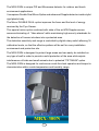
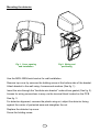
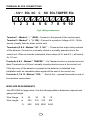
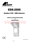
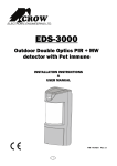
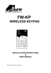
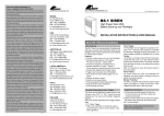
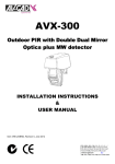
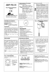
ELECTRONIC ENGINEERING LTD.
MRXMRX-300N
Outdoor PIR + MW Detector
with Double Dual Mirror Optics
INSTALLATION INSTRUCTIONS
&
USER MANUAL
P/N 7101297 Rev. A Y.S/A.Y
1
The MRX-300N is unique PIR and Microwave detector for outdoor and harsh
environment applications.
It comprises Double Dual Mirror Optics and advanced Doppler detector inside stylist
rigid plastic body.
The Mirror DOUBLE DUAL optics improves the focus and the level of energy
received by the Pyro Sensor.
This special mirror optics combined with state of the art MW Doppler sensor
assures eliminating of “false alarms” while maintaining high security standards for
the detection of human intruders into a protected area.
The detection sensitivity and range is controlled by digital rotary switch allowing 16
calibration levels, so that the effective pattern will be set for every installation
environment and protection site.
The MRX-300N is designed to protect large areas and can easily be installed on
any type of wall in order to provide a solid protection of the area while rejects
interferences of birds and small animals due to patented “PET MASK” optics.
The MRX-300N is designed for continuous round-the-clock operation and keeps its
characteristics within a wide temperature and humidity range.
MRX-300N
2
MRX–300N FEATURES
• DOUBLE DUAL PYRO sensor.
• Full pattern double mirrors optics.
• MW detection based on Doppler concept.
• FET based DRO with strip line antenna.
• VLSI based electronics with movement speed spectrum analysis.
• N.O. & N. C. Relays switched at the same time.
• Height installation calibrations free, from 1.5m to 3.0m
• Pet Immunity up for pet and small animals up 40kg.
• 16 levels of MW and PIR sensitivity adjustment.
• Environmental immunity.
• Temperature compensation.
• Micro controller signal processing.
• Tamper and tilt full protection.
• Walk test and detection sound indication.
• Unique waterproof and seal plastic design.
• Detection Range: Up to 40m (with LR Mirrors)
• Detect human intruders walking, running or crawling.
• No maintenance required.
• High RFI/EMI Immunity.
• Protection from: direct sunlight, wind up to 30 m/sec, snow and rain, small
animals, removing the top cover, housing pulling out or destruction.
3
Selecting mounting location
The installation of the MRX-300N requires straight and solid base for the detector
and setting of front panel against the center of protected area.
Local conditions of the protected zone must be free from obstacles like walls,
fences, trees and ditches or other microwave detectors and systems of
anti-intrusion surveillance.
The bracket provides MRX-300N installation on the wall, allows changing the
installation angle (vertically and horizontally) in wide range (FIG.2).
The wall should be leveled with a maximum slope angle of 10°.
Choose a location most likely to intercept an intruder according to detection pattern
in FIG.: 6.
Avoid the following Installation Locations:
• Facing direct sunlight.
• Facing areas subject to rapid temperature changes.
• Wall angle of more then 10º from perpendicular line.
• Mounting at more then 10º Deviation from horizontal line.
• Facing metal doors.
• Avoid installation of MRX-300N on the following type of ground: Thick
vegetation, Grass (un-mown), Water, Sand and a Metal.
NOTE:
Recommended installation height is 3m.
The DOUBLE DUAL high quality sensor detects motion crossing the beam; it is
less sensitive detecting motion towards the detector.
The MRX-300N performs best when provided with a constant and stable
environment.
In order to ensure suitable operation of the MRX-300N type of ground should be
one of the following: Asphalt, Cement, Soil, Clay, Gravel or Grass (mown).
4
Mounting the detector
Fig.1. Cover opening
and Installation
Fig.2. Wiring and
positioning
Use the MRX-300N back bracket for wall installation.
Remove top cover by unscrew the holding screw at the bottom side of the bracket.
Attach bracket to the wall using 4 screws and anchors (See fig. 1).
Insert the wire through the “line/hole wire bracket” under silicon gasket (See fig. 2).
Access for wiring connections is easy via the terminal block located on the PCB.
See fig. 3.
For detector alignment, unscrew the plastic wing nut, adjust the detector facing
against the center of protected area and straighten the nut.
Replace the detector top cover.
Screw the holding screw.
5
TERMINAL BLOCK CONNECTIONS
- 12V + EOL NC C NO EOL TAMPER EOL
1
2
3
5 6
4
7 8
9 10
Fig.3. Wiring connections
Terminal 1 - Marked “ - ” (GND) - Connect to the ground of the control panel.
Terminal 2 - Marked “ + ” (+12V) - Connect to a positive Voltage of 8.2 -16Vdc
source (usually from the alarm control unit)
Terminals 4,5 & 6 - Marked “ NC C NO ” - These are the output relay contacts
of the detector. Connect to a normally closed or normally opened zone in the
control unit. When an intruder is detected, alarm relays (N.O. and N.C.) will switch
for 1.8 sec.
Terminals 8 & 9 - Marked “ TAMPER ” - If a Tamper function is required connect
these Terminals to a 24-hour normally closed protective zone in the control unit.
If the top cover of the detector is opened or the detector is detached from
installation wall, an immediate alarm signal will be sent to the control unit.
Terminals 3,7 & 10 - Marked “ EOL ” - End of line – optional terminals for end of
line resistors connections.
WIRE SIZE REQUIREMENTS
Use #22 AWG or larger wires. Use the following table to determine required wire
gauge and length.
Wire Gauge:
#
22
20
18
16
Wire Length:
m
205
310
510
870
Ft.
800
1200 2000
3400
6
TOP PCB LAYOUT
Block Connector
Tilt Mode
Jumper (JP4)
LED Mode
Jumper (JP2)
Buzzer Mode
Jumper (JP3)
Rotary Switch
Fig.4. Interface PCB layout
LED INDICATORS
YELLOW LED
- MW detection, is blinking during warm up period and self testing
GREEN LED
- PIR detection
RED LED
- Alarm
7
TEST AND TUNING
SENSITIVITY AND RANGE ADJUSTMENT
The calibration of range and sensitivity is performed by single digital 16 position
rotary switch.
There are 3 groups of switch setting according to detection range.
Each group is divided to several levels of sensitivity according to installation
environment.
The sensitivity levels values changed upon the mirror optic type.
Low Risk
Risk
WA
Risk
Low Risk
7m
E
2
High Risk
D
High Risk
Very High Risk
3
Noise Area
C
4
Extreme Noise Area
B
5
A
WA
6
9
7
Low Risk
8
15m
Risk
High Risk
Very High Risk
Installation Hight: 3m
Bracket Angle: 0°
Noise Area
Fig.5. Rotary switch setting
8
LR
28m
Low Risk
15m
High Risk
1
21m
F
Very High Risk
LR
Low Risk
0
Noise Area
High Risk
LR
40m
WA
Low Risk
High Risk
For WA (Wide Angle) mirror optic
TOP VIEW
WA mirror 90.5 ° (PIR)
10m
MW pattern
5m
0m
21m
30m
5m
10m
`
SIDE VIEW
2.4m
5m
10m
21m
30m
Fig.6. WA PIR + MW Detection Pattern
Group A - positions 0 – 5 – set sensitivity for 21m detection range
Group B - positions 6 – A – set sensitivity for 15m detection range
Group C - positions B – F – set sensitivity for 7m detection range
For LR (Long Range) mirror optic (optional Model MRX-300N-LR)
Group A - positions 0 and 1 – set sensitivity for 40m detection range
Group B - positions 6 and 7 – set sensitivity for28m detection range
Group C - positions B and C – set sensitivity for 15m detection range
Each range group includes 5 or 6 setting levels according to environmental
condition risk.
For example:
If detector is used for 15m range in open space with sunlight – set switch to position
8 or 9.
9
JUMPERS SETTING
LED Mode Jumper (JP2)
Connect a jumper between the marked terminals to enable or disable the LED (ON
or OFF).
OFF
LED
ON
LED OFF
OFF
LED
ON
LED ON
Buzzer Mode Jumper (JP3)
Buzzer provides the sound indication of Alarm signal.
If a buzzer function is required, connect a jumper in position ON, if it is not required
– in position OFF.
BUZZER
OFF
Buzzer OFF
ON
BUZZER
OFF
Buzzer ON
ON
The buzzer function is useful during walk test when sunlight dazzling the LED.
Tilt Mode Jumper (JP4)
Two tilts protect detector from undesirable attempts to pull off from installation
place.
Tilts fix position change also in horizontal and vertical directions and send signal
to Tamper terminals.
If a tilt function is required, connect a jumper in position ON, if it is not required – in
position OFF.
OFF
TILT
ON
Tilt OFF
OFF
TILT
ON
Tilt ON
You must reset the detector from Control Panel before the new
settings will take effect
10
Test procedure
Walk Test
After tuning the sensitivity, connect 12Vdc power to the system.
Allow 2 minute warm-up time.
Make sure that the protected area is cleared of all people.
1. Start walking slowly across the detection zone.
2. Listen to ALARM sound whenever motion is detected (The red LED lights also
whenever motion is detected).
3. Allow 5 sec. between each test for the detector to stabilize.
NOTE: Walk Test procedure should be conducted, at least once
a year, to confirm proper operation and coverage of the
detector.
11
SPECIFICATIONS
Optic Detection Method
DOUBLE DUAL element PIR & MW
90.5° with 30 zones detection
WA Mirror Pattern
Microwave Frequency
10.525 GHz +/-3MHz
Microwave Output Power
Min. + 13dBm IERP
Microwave Harmonic emission
- 7.3dBm
Scope (Length of protection zone)
Max. 21m (WA mirror) max10. 40m (LR mirror)
Power Supply Voltage
Current consumption
Relay contacts values
8.2...16 V
Active: 27mA ± 3mA
Standby: 17mA ± 3mA
N.C 28Vdc 0.1 A with 10 Ohm protection resistors
N.O 28Vdc 0.1 A with 10 Ohm protection resistors
Warm up Period
120 Sec (Max.)
Alarm Period
1.8 Sec (Max.)
Tamper Switch
N.C 28 Vdc Maximum current 0.1 A - open when
cover is removed
Detection Speed (Target velocity)
0.3 ... 3 m/sec
Dimensions of unit with bracket
192mm x 153mm x 251mm
Weight
0.55 Kg
-20°C ~ +60°C
Operating temperature range
•
•
Weatherproofing
RFI Protection
EMI Protection
Visible Light Protection
All openings with gasket and sealed
IP 65 compatible
30V/m 10 – 1000 MHz
50,000V of electrical interference from lightning or
power through
Stable against halogen light, sunlight or reflecting
light
* Specifications are subject to change without prior notice.
12
CROW LIMITED WARRANTY
(CROW) warrants this product to be free from defects in materials and
workmanship under normal use and service for a period of one year from
the last day of the week and year whose numbers are printed on the printed
circuit board inside this product.
CROW’s obligation is limited to repairing or replacing this product, at its
option, free of charge for materials or labor, if it is proved to be defective in
materials or workmanship under normal use and service. CROW shall have
no obligation under this Limited Warranty or otherwise if the product is
altered or improperly repaired or serviced by anyone other then CROW.
There are no warranties, expressed or implied, of merchantability or fitness
for a particular purpose or otherwise, which extend beyond the description
on the face hereof. In no case shall CROW be liable to anyone for any
consequential or incidental damages for breach of this or any other
warranty, expressed or implied, or upon any other basis of liability
whatsoever, even if the loss or damage is caused by CROW’s own
negligence or fault.
CROW does not represent that this product can not be compromised or
circumvented; that this product will prevent any person injury or property
loss or damage by burglary, robbery, fire or otherwise; or that this product
will in all cases provide adequate warning or protection. Purchaser
understands that a properly installed and maintained product can only
reduce the risk of burglary, robbery or other events occurring without
providing an alarm, but it is not insurance or a guarantee that such will not
occur or that there will be no personal injury or property loss or damage as a
result. Consequently, CROW shall have no liability for any personal injury;
property damage or any other loss based on claim that this product failed to
give any warning. However, if CROW is held liable, whether directly or
indirectly, for any loss or damage arising under this limited warranty or
otherwise, regardless of cause or origin, CROW’s maximum liability shall
not in any case exceed the purchase price of this product, which shall be
the complete and exclusive remedy against CROW.
13
ELECTRONIC ENGINEERING LTD.
ISRAEL:
CROW ELECTRONIC ENGINEERING LTD.
57 Hamelacha St., Holon 58855
Tel: +972-3-5569937
Fax: +972-3-5592981
E-mail: [email protected]
USA:
CROW ELECTRONIC ENGINEERING LTD.
2160 North Central Road,
Fort Lee, N.J. 07024
Tel: 1-800-GET-CROW or +201-944-0005
Fax: +1-201-944-1199
E-mail: [email protected]
AUSTRALIA:
CROW AUSTRALIA PTY. LTD.
429 Nepean HWY Brighton East Vic 3187
Tel: +61-3-9596-7222
Fax: +61-3-9596-0888
E-mail: [email protected]
POLAND:
VIDICON
UL. PLOCKA 17,
01-231 WARSZAWA, POLAND
Tel: +48-22-632-5543
Fax: +48-22- 631-3808
E-mail: [email protected]
LATIN AMERICA:
CROW LATIN AMERICA
168 SE IST Street, Suite # 501, MIAMI,
FL 33131 – USA
Tel: +1-305-372-0334
Fax: +1-305-372-8053
E-mail: [email protected]
ITALY:
DEATRONIC
VIA Giulianello 4/14
00178 ROMA, ITALY
Tel: +39-0676-12912
Fax: +39-0676-12601
E-mail: [email protected]
14