1
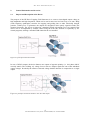
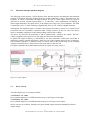
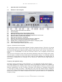
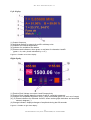
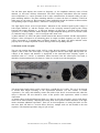
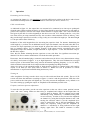
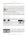
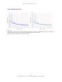
HF-Drive Manual_1_1.doc 13 - June - 2012 Manual Rev. 1.1, June 2012 Versions HF-Drive 5.5 - 1250, HF-Drive 3.5 - 1600 www.stahl-electronics.com HF - Drive Short Manual, Rev 1.1 TABLE OF CONTENTS 1. Safety Hints ………………………………….…………………………………… 3 2. General Information and Overview………………….………………………….. 4 2.1 2.2 2.3. Purpose and Description of the Device…………………………….. Functional Principle and Block Diagram…………………………. Device Variety……………………………………………………… 4 5 5 3. Installation ……………………………………………………………………..… 6 3.1. Mechanical and Electrical Installation……………………………… 6 4. Operation and Control Elements …………………………………………………….. 7 4.1 4.2 Elements on the front plate………………………………………… Elements on the rear plate ………………………………………… 7 9 5. Operation ……………………………………………………………………….. 10 6. Maintenance………………………………………….…………………………. 13 7. Specifications……………………………………………………………………. 14 2 www.stahl-electronics.com phone: +49 6242-504882, fax: +49 6242 504884 HF - Drive Short Manual, Rev 1.1 1. Safety Hints Read all installation, operation, and safety instructions Hazard of RF Power Output Rear side switch turns device completely off This equipment must be connected to an earth safety ground Do not modify the unit Do not operate in wet/damp conditions Beware of external magnetic fields Service is to be performed by qualified service persons only Do not block chassis ventilation openings Routinely cleaning from dust No outdoor operation Prior to operation, thoroughly review all safety, installation, and operating instructions accompanying this equipment. This device emits radio-frequency signals at its output. The high power and related high voltages are harmful in case of direct touch with the human body and put damage or harmful interference to electronic devices. Care and safety precautions have to be taken appropriately. Effective emitted power is in the several Watt range, whereas reactive Power amounts to nearly 1kW each output. If the device is not in use for a longer time, it is recommended to turn the mains switch at the rear side off. This product is grounded through the grounding conductor of the power cord. To avoid electrical hazard, the grounding conductor must be connected to protective earth ground. Do not make electrical or mechanical modifications to this unit. To avoid electric shock hazard, do not operate this product in wet or damp conditions. Protect the device from humidity and direct water contact. External magnetic fields can impair, damage or even destroy this device. A maximum external field strength of no more than B = 10mT is admissible. Having placed the device at any time into an external magnetic of bigger B = 10mT (regardless if power was turned on or off) can lead to severe overheating of the device and severely increased hazard of fire. All servicing on this equipment must be carried out by factory-qualified service personnel only. Slots and openings in the chassis are provided for ventilation purposes to prevent overheating of the equipment and must not be restricted. All case vents should continuously be cleared (fan inlet at rear side, air outlet at rear and top side), in order to prevent overheating. If mounted in a rack, please allow 5cm clearance at the top cover with respect to the next device above. A temperature over 60°C as indicated on the front screen courses problems. After long operation, or operation in a dusty environment it is strongly recommended to have the internal parts of the device cleaned by the manufacturer, or an appropriately qualified workshop in order to reduce the hazard of overheating. Outdoor operation of the device is not admissible. 3 www.stahl-electronics.com phone: +49 6242-504882, fax: +49 6242 504884 HF - Drive Short Manual, Rev 1.1 2. General Information and Overview 2.1 Purpose and Description of the Device The purpose of the HF-Drive Trapping Field Generator is to create a sinus-shaped output voltage at high amplitudes and high frequencies, which can be used to store ions in a Paul Trap, or to run a RFQ (radio frequency quadrupole) structure for trapping and guiding ions or other electrically charged particles. Unlike power rf generators, the outputs are designed to drive purely capacitive loads, like electrical electrodes. The device is housed in a standard 19-inch rack-mount case. User control of the device can be accomplished by manual control using the front side elements or optionally by PC control programs, utilizing a standard USB connection in case installed. Figure 2.1 principle connection scheme In case of DUAL-outputs, the device features two outputs of opposite polarity (i.e. 180° phase shift if correctly tuned). The resulting AC voltage between the two outputs equals the sum of the individual output voltages. Practically the effective electrode voltage doubles therefore in comparison to a single output. Figure 2.2 principle connection scheme in case of a dual output 4 www.stahl-electronics.com phone: +49 6242-504882, fax: +49 6242 504884 HF - Drive Short Manual, Rev 1.1 2.2 Functional Principle and Block Diagram The following picture displays a block diagram of the internal structure and illustrates the functional principle. The internal precision oscillator (based on a DDS synthesizer) creates a sinusoidal wave, the frequency of which is controlled with high-resolution. In case of a dual output device, the signal is split into an inverted and non-inverted path (i.e. 0° and 180°). After amplification and filtering to reduce higher harmonics, the signal arrives at the output power stage (PA, power amplifier). The latter is operated in “class-A” mode, resulting in high linearity and very low content of higher harmonics. Subsequently the amplified signal is coupled to the external electrodes by means of a resonant circuit (-network) and low capacitance connection cable. Tuning capacitors at the rear side of the device allow for trimming asymmetries in the cabling leading to the ion trap or RFQ. The device also provides the possibility to add an additional DC voltage to the outputs. This DCvoltage is applied to the respective rear side input (not shown in block diagram). In general the output frequency is determined by the load capacitance (cables plus electrodes) in conjunction with the internal inductances, which are part of the resonant output circuits (-network). This resonance frequency is generally fixed, but can be tuned in the percent-range by the trimming capacitors mentioned above, located close to the cable outlets at the rear side. For further comments and commissioning/operation procedure see below section 5. Figure 2.3: block diagram 2.3. Device Variety The following devices are currently available: The HF-Drive 3.5 - 1600 has a resonant frequency of 3.5MHz and delivers up to 1600 Vpp at each output. The HF-Drive 5.5 - 1250 has a resonant frequency of 5.5MHz and delivering up to 1250 Vpp at each output. DUAL versions are available, featuring 180° phase shifted outputs, therefore doubling the effective output voltage. 5 www.stahl-electronics.com phone: +49 6242-504882, fax: +49 6242 504884 HF - Drive Short Manual, Rev 1.1 3. Installation 3.1. Mechanical and Electrical Installation Positioning: It is mandatory to provide sufficient air cooling to the device and to locate in normal horizontal position to allow for defined air convection. Rack mounting into a standard 19” rack is as well possible as resting the device on a table. Important: If mounted in a rack, allow at least 10cm clearance at the top cover with respect to the next device above. All case vents must permanently be cleared (fan inlet at rear side, air outlet at rear and especially on top side), in order to prevent overheating. Beware of external magnetic fields: Strong external magnetic fields can impair, damage or even destroy this device (e.g. proximity to a superconducting magnet). A maximum external field strength of no more than B = 10mT is admissible. Not observing this important condition can lead to severe overheating of the device and increased hazard of fire. Connecting to mains power: Connect the device to the mains power supply by using an appropriate power cord, being properly wired and providing a grounded outlet. The power cord must be suited with respect to possible load currents and should be rated to at least 10A current. Cabling of voltage outputs: Always provide appropriate and safe cabling when connecting the device to other devices or vacuum/experimental setups. Due to the considerable hazard, connected to the high output voltage, either use the cables which are already connected to the device, or use prolongations of appropriate quality and rating. All cable extensions, attached plugs, connectors and sockets must be able to carry the maximum voltage of 1600Vpp and current of approx. 4 App at high frequencies (up to 5.5MHz). They also must withstand an averaged reactive power of about 800 Watt, being rated at the nominal operating frequency (3.5 to 5.5 MHz), which oscillates between each device output and the trap/RFQ electrodes. Always be aware of the potential hazard of high electrical voltages to human beings and sensitive objects of all kind (see also safety hints in section 1). In case of any doubts about the integrity of the setup or its cabling, rather take measures of care, avoiding unnecessary risks. Concerning the admissible amount of radiation, please refer to the legal regulations at site of operation. Please note that changes of cabling may only be done when the device is turned off. Connecting a powered-up output to external circuitry can easily cause sparks and severe electrical discharges. The resulting overvoltages can severely and permanently damage the device itself and also external circuitry and can endanger human beings. 6 www.stahl-electronics.com phone: +49 6242-504882, fax: +49 6242 504884 HF - Drive Short Manual, Rev 1.1 4. Operation and Control Elements 4.1 Elements on the front plate (1) (2) (3) (4) (5) (6) (7) (8) (9) (10) (11) (12) Power-On switch and Power LED indicator Control Display Analog Amplitude Control Inputs (Ordering Option) Blank input to suppress the output signals (5V / 0V) Fine lock switch for enabling the automatic amplitude fine lock function Buttons to select frequency and amplitude Digit selection (frequency, amplitude) Selection and parameter change wheel (frequency, amplitude) Mute selection to temporarily suppress the output signals Disable switch to disable the power output stages in emergency cases Monitoring display (details see below) Test or Phase Synch Output (Logic level 5V/0V). Figure 4.1: Elements on the front plate The front plate contains several control elements in order to operate the device. The device is powered up after turning on the rear-side mains supply switch and also the Power-On button on the front plate. The Power-on-LED (green) indicates proper operation of the internal +24V circuitry. If the device is not in use, it is recommended to use the rear side mains switch to cut it completely off from mains supply. There are two LCD displays on the front side showing information about device settings and its status. The left display is mainly concerned with frequency and amplitude settings. Two internally measured temperatures are also shown as well as the status of the two (most important) air ventilation fans. In case of severe malfunctions error messages are also shown here. Details about the right display are given below. Frequency and amplitude setting Operation is mostly carried out by using the buttons 6, 7, 9 in conjunction with the selection wheel 8. The output amplitudes of channels A and B are chosen by defining the internal drive amplitude in percent and looking on the resulting output voltage on the right display. Frequency is chosen for both channels simultaneously. In order to change a parameter select frequency or amplitude using buttons 6, select digit to change by buttons 7 and change the value using the selection wheel 8. Buttons 9 accounts for muting (suppressing) the output signal temporarily by decreasing the internal amplitude. Please refer to section 5 for further description of the device operation and the use of amplitude and frequency settings. 7 www.stahl-electronics.com phone: +49 6242-504882, fax: +49 6242 504884 HF - Drive Short Manual, Rev 1.1 Left display (1) Output frequency (2) Amplitude setting for outputs A and B in arbitrary units. (3) Indicator for internal temperature (4) Indicator for ventilation fan rotation (5) Phase match indicators, show green or red letter for channels A and B (green = ok, red = phase mismatch by >= 9°) Figure 4.2: Details on left front display Right display (1) Peak-to-Peak Voltage on output A and B respectively (2) Peak-to-Peak Voltage between outputs A and B, vectorially measured (3) Indicator for Amplitude Regulation Loop, if loop is activated (green: ok; red: out of range) (4), (5) Phase indicators for channels A and B, shown as bar-graph indicators and numerical values in degrees (°) (6) Change indicator, displays changes of amplitude during last 30 seconds Figure 4.3: Details on right front display 8 www.stahl-electronics.com phone: +49 6242-504882, fax: +49 6242 504884 HF - Drive Short Manual, Rev 1.1 The left front plate displays the current set frequency (1), the amplitude (arbitrary units) of both channels (2) and some auxiliary information. The latter comprises information about the internal device temperature (3), correct operation of the 2 major ventilation fans for internal cooling (4) and a phase matching indicator. The phase matching indicator (5) shows the letter of channels A and B in either green or red colour (6). Red represents a phase mismatch between the internal oscillator and the corresponding output of larger than 9°, otherwise it is displayed in green. The right display shows measured parameters. Indicated are the measured peak-to-peak voltage of both output channels (1) and the absolute value of the vectorially measured peak-to-peak voltage between both output channels (2). A PID loop indicator (if PID loop is activated) shows the loop operation (3), a change indicator makes changes of output amplitude during the last 30 seconds visible (6). Indicator range is roughly +/-20% of averaged value, linear scale. A phase indicator (5) shows the phase relation between the internal oscillator and the output phases. Negative values correspond to an advancing phase at output (oscillator frequency too low), positive values correspond to a retarded phase (oscillator frequency too high). The phase indicator works properly above an output amplitude of about 200Vpp on the corresponding channel. 4.2 Elements on the rear plate The rear side contains the mains switch, 230Vac socket, the main outputs A and B (also designated as outputs 1 and 2) and a DC offset input. A voltage applied to the DC offset input adds up to the AC voltages at the outputs and therefore is superposed to the sinusoidal radio frequency signals. A maximum value of +/-350VDC is admissible. Please note that if the DC offset input is not used, it should be closed (terminated) by 50 Ohms or a short cur, in order to prevent charging up. Figure 4.4: Picture of rear side The main output signals appear on the coaxial lines A and B (RG 62 A cable). The user is encouraged to shorten their length according to the experimental demands (see also remarks in section “operation”). For safety and reliability reasons the cables of the device are non-removable, when the device is delivered. The user should be aware of the specific cable capacitance, which is around 43pF/meter. As already shown in the block diagram (figure 2.3), there are two trim capacitors, one for each output, which can be tuned manually. Adjusting the turning knob in left position means minimum, to the right means maximum additional capacitance. There are no fixed endpoints, so turning the knob over the max./min. limit will lead to a reversal effect. However, multiple turns are not harmful to the trim capacitors. The nominal capacitance range is 5pF to 55pF. 9 www.stahl-electronics.com phone: +49 6242-504882, fax: +49 6242 504884 HF - Drive Short Manual, Rev 1.1 5. Operation Positioning and Air Cooling As expressed in chapter 3.1 it is mandatory to provide sufficient air cooling to the device and to locate in normal horizontal position to allow for defined air convection (see above, section 3.1). Cable considerations As indicated in figure 2.2, the output lines are assumed to be connected to an ion trap or quadrupole electrode setup. Before turning the device on, these lines should be tested for shortcuts to each other or ground. The capacitive load on each output should amount to roughly 90pF. This value includes the load given by the RG 62A cable beginning at the device rear side. As a starting point for a very first run of the device (no setup attached) one may also use these cables attached at state of delivery, since they provide 84pF capacitive load each, as long as they are not reduced in length yet. The initial length is 1.8m per cable at state of delivery. Reduction of the cable length allows for increasing the capacitive load. For instance diminishing the cable length by 1 m allows for an additional load of 43pF each channel, since the used cable (RG 62A) accounts for 43pF capacitance per meter length. In general the cables can be arbitrarily shortened, as long as geometry allows. To give another example, if the setup parasitic capacitances have been measured to 50pF each channel, a length reduction of 50pF/43pF/m = 1.16m will match the setup to the HF-drive outputs. Note, that for further trimming the trim capacitors at rear side allow for significant corrections per channel. Feel free to contact manufacturer if in doubt about this procedure. Please note, that all attached plugs, connectors and sockets must be able to carry the maximum voltage of 1600Vpp and current of approx. 4 App at high frequencies. They also must withstand an averaged reactive power of about 800 Watt, being rated at the nominal operating frequency (3.5 to 5.5 MHz), which oscillates between each device output and the corresponding trap/RFQ electrodes. Always be aware of the potential hazard of high electrical voltages to human beings and sensitive objects of all kind (see also safety hints in section 1). Rather run safe in operation or consult manufacturer or experienced staff than taking unnecessary risks. Turning on After completion of wiring, turn the device on (rear side switch and front side switch). The two LCD screens will show the indicators according to figures 4.1 and 4.2 and the green Power LED above the power switch at the front plate will lighten up. For safety reasons the amplitudes are by default set to zero after starting up, putting the output AC amplitude to the minimum possible value. Frequency and trim capacitor adjustment To start the trim procedure, put the two trim capacitors at the rear side to center position between “min.” and “max” setting. Make sure that wiring is completed and voltages on the output lines can cause no harm or damage. The two outputs can be tuned individually, being followed by a combined tuning later in case necessary. In order to start, increase the amplitude on channel A by using the front plate buttons 6 and 7 and turning the selection wheel 8. Set the amplitude drive value to around 50%, not to full load immediately. Now change the frequency setting until the amplitude on channel A is maximum, as being indicated on the right display, upper lines. The width of resonance is about 10 www.stahl-electronics.com phone: +49 6242-504882, fax: +49 6242 504884 HF - Drive Short Manual, Rev 1.1 100kHz, so choose the step size with the arrow buttons ← and → appropriately when changing the frequency in order to find the maximum. frequency Figure 5.1: symbolic representation of the tuning process: tune the frequency to maximize the output amplitude. Repeat this procedure for the second channel to complete this tuning step. Both resonance frequencies should not differ by more than +/-5%. To finalize tuning and trimming, choose now a frequency value, roughly centered between the two resonant frequencies determined before. Set this value with the controls and tune the output trim capacitors (located at rear side of the device) on channels A and B slowly to achieve maximum amplitude on each channel. Now one may increase the drive amplitude on channels A and B to a value, when the output voltages do not further increase much, reaching a saturation level (usually between 80 and 100% of nominal setting). Slightly go back in drive level to reduce generation of higher harmonics. As a last step a fine trim of the capacitors and/or the frequency can be made using the phase indicator on the right display. If the frequency and capacitor values are correctly adjusted the phase figure equals zero, see also (4) and (5) in figure 4.3. To change the resulting voltage difference between the two outputs A and B (indicated in large letters in the center of the right display), one may vary the two driving levels individually or together to obtain a balanced signal with equal amplitudes on both channels. Note that the voltage difference depends both on relative phase and amplitudes of channels A and B. In case both outputs are trimmed correctly, the resulting phase difference amounts to 180°. The displayed voltage difference is the vector difference of both output voltages. Using the phase indicators (see figure 4.2) the phase relations are even easier to observe, i.e. the relative phases between internal drives and outputs can be monitored. Note that negative values correspond to a retarded phase at output, which means that the oscillator frequency is too low, positive values correspond to an advancing phase, i.e. oscillator frequency is too high. The phase indicator works properly above an output amplitude of about 300Vpp on the corresponding channel and will show erratic values at lower amplitudes. For initial tuning after cabling (usually amplitudes are smaller than 300Vpp), the phase indicators are not a suited tool to find the resonance. Power-Amplifier Switch The power amplifier switch, which is located at right side of the turning wheel, may be used to disable both power amplifier (PA) output stages (see also block diagram fig. 2.3). In the lower position the output stages are completely turned off, otherwise turned on (upper switch position). This switch may be used to keep the device on, but reducing power consumption and heat generation. The 11 www.stahl-electronics.com phone: +49 6242-504882, fax: +49 6242 504884 HF - Drive Short Manual, Rev 1.1 latter is reduced by approximately 200W, when the internal PA stage is disabled. Please note that if the outputs are disabled (PAs off) the hold switch (see below) is not operational. Hold Switch Once the desired output voltage has been set, a PID-loop based “fine lock” circuit may be enabled in order to keep the output voltage difference constant. First, the switch should be brought to the “measure” position. Subsequently frequency, amplitude and phase should be adjusted. After completion of these settings one may bring the switch to the “hold“ position. It reacts specially on a “double” trigger, which means one should switch quickly twice from “measure” to “hold” in less than 2 seconds. The internal circuitry will now try to settle the amplitude chosen before by readjusting the amplitude settings of both channels. As long as the regulation loop succeeds to keep the voltage difference constant, the PID-indicator on the right front display is highlighted green. If the PID-loop is not able anymore to keep the set parameters, the highlighted background becomes red. It is then advised to bring the switch into the position “measure”, to set a lower amplitude or check the reason (i.e. maybe a change of load) why the set amplitude could not be kept fix. Please note that once the switch is in the “hold” position, any operation on the manual entry keys (frequency amplitude, mute) might lead to erratic behaviour, since the internal loop will try to keep the formerly detected voltage difference constant by changing internal parameters in time. Therefore check once in a while whether the switch position is really “measure” in case the “fine-lock” PID-loop is not in use. Mute Switch and Blanking Input In order to temporarily suppress the AC output signal of the RF drive, one can operate the “mute” buttons on the front plate. Both AC output amplitudes will be set to zero when the button “off” is pressed and will return to the former value when “on” is pressed again. The same effect is achieved by the application of a +5V logic level signal to the “Blank In” input on the front plate (underneath the left display). Also in this case the AC output amplitudes will be set to zero and will be restored when the input is brought to 0V again or left open. Note: If the outputs are muted, the hold switch (see above) is not operational; however the “fine-lock” circuitry still holds the formerly set value in that case. So after bringing back the device from muted into normal mode, the PID loop will try to re-establish the formerly set output voltage difference again. Phase Monitoring Output In case this option is installed, the BNC connector underneath the right display will output a logic level 5V/0V signal, which is phase-synchronized to the internal oscillator. This feature may be used to synchronize flourescence photon detection in ion-trap laser experiments to the micro motion of particles. Please note that the phase readings (shown on the right display) should be brought to zero (by trimming the trim capacitors on the rear side of the device) or at least their values be observed. 12 www.stahl-electronics.com phone: +49 6242-504882, fax: +49 6242 504884 HF - Drive Short Manual, Rev 1.1 6. Maintenance Under normal operating conditions, the device should not require electrical maintenance, except routine cleaning of dust. Exchange of ventilation fan is strongly recommended every 35’000 operation hours (see below). If any question should arise, please contact the manufacturer. Routine cleaning All ventilation openings – top, bottom, sides, and rear panel – should be checked periodically and kept free of dust and other obstructions. A vacuum cleaner may be used to clean these vents when the unit is powered off. Do not use compressed air to clear the vents. The front panel may be cleaned periodically with a clean cloth and mild alcohol solution, when the unit is powered off. It is recommended to send the device to the manufacturer routinely in 2-year intervals for internal cleaning from dust. Fire hazard Please note that excessive accumulation of dust inside the case of the device can lead to overheating. This, together with possible discharges increases the risk of fire, caused by electrical sparks. Routinely cleaning the device from dust minimizes this risk. It is therefore recommended to send the device to the manufacturer routinely in 2-year intervals for internal cleaning from dust, or to have it cleaned by an accordingly qualified electronical workshop. Also air conditions containing oil mists (e.g. proximity to a vacuum pump or mechanical machines) place a severe danger, since enflammable substances could enter the device through the ventilation holes. If in doubt, cleaning by an accordingly qualified electronical workshop or the manufacturer is strongly recommended. An increased hazard of fire may also occur if the device has been (permanently or temporarily) located in proximity to a strong (e.g. superconducting) magnet. A maximum external field of B = 10mT is admissible. Decommissioning Decommissioning of the device is recommended after latest 130’000 hours of operation. Please contact manufacturer for appropriate waste disposal and observe applicable legal regulations. 13 www.stahl-electronics.com phone: +49 6242-504882, fax: +49 6242 504884 HF - Drive Short Manual, Rev 1.1 7. Specifications ____________________________________________________________________________ Output Characteristics Output resonant frequency Maximum output voltage per channel Version “HF-Drive 3.5” 3.5 MHz nominally Version “HF-Drive 5.5” 5.5 MHz nominally HF-Drive 3.5: HF-Drive 5.5: Nominal output load vs. GND (each channel) Nominal output load difference (between both channels) 1600Vpp nominally 1250Vpp nominally 90 pF vs. GND including cabling of device itself < 10pF approx. +/-6% of center frequency capacitive trim range 5pF … 55pF each channel Tuning range Suppression of higher harmonics typ. > 65dB @ output amplitude 500Vpp … 1000Vpp Digital Inputs and Outputs Synchronization output Signal shape: rectangular signal 5V/ 0V, load max. 250pF, high impedance expected Jitter: typ. 1.2ns peak-peak (HF-Drive 5.5) Polarity: zero transition rising-edge on synchronization output occurs on zero transition falling-edge on output A accepts 5V/ 0V logic levels, high input impedance Blank input 5V => output amplitude off 0V => output amplitude on Environmental Conditions max. B = 10 mT admissible Magnetic Field -55 C° to +85 C° Storage Temperature Operating Humidity & Temperature noncondensing relative humidity up to 95% between temperatures of +10°C and +35°C. Power Supply AC Supply Rating Power Consumption Case dimensions Weight AC input voltage 230VAC at 50Hz. The power entry module is EMI/RFI-filtered. Fuse: medium fast blow 10A typ. 235W at full ,load, max. 265 W 19.00” wide x 3 height units. Front-panel mounting holes are configured for M6 rack configurations approximately 17kg, configuration dependent 14 www.stahl-electronics.com phone: +49 6242-504882, fax: +49 6242 504884 HF - Drive Short Manual, Rev 1.1 Typical Output Harmonics Figure 7.1: Output harmonics observed at 500Vpp and 1000Vpp output voltage. The fundamental wave and 2nd harmonic is visible, higher harmonics are lower than the background noise level observed. Measurement device: HM5014-2 spectrum analyzer. 15 www.stahl-electronics.com phone: +49 6242-504882, fax: +49 6242 504884