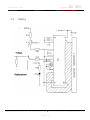
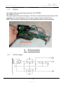
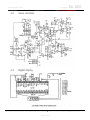
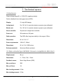
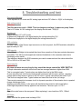
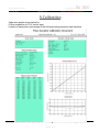
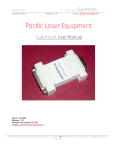
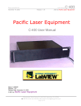
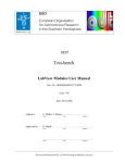
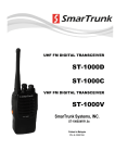
1
Servo Amplifier 1ch-1000
User manual
April 28, 2004
Release: 1.21
1SA-1000
2003 by Pacific Laser Equipment
Pacific Laser Equipment, Inc.
1SA-1000 User Manual
Name: 1SA-1000UM
Release: 1.21
Release Date: April 28, 2004
© 2001 by Pacific Laser Equipment
PLEquipment, 3941 S. Bristol St. Unit E, # 122, Santa Ana, CA. 92704, ( & Fax: 509-355-5155, Email: [email protected]
Page 1 of 16
Servo Amplifier 1ch-1000
User manual
April 28, 2004
Release: 1.21
1SA-1000
2003 by Pacific Laser Equipment
Table of contents:
1. Introduction
3
2. Block diagrams
2.1
General
2.2
Servo controller
2.3
2.3 Display
5
3. Blocks description
3.1
General
3.2
Description
3.3
Display
8
4. Schematics
4.1
Power
4.2
Servo controller
4.3
Display
9
5. Piezo actuator
11
6. Strain Gage Sensor
12
7. Technical specs
7.1
Electronics
7.2
Piezo actuator
13
8. Troubleshooting and test
14
9. Calibration diagram
15
10. Addendum
16
PLEquipment, 3941 S. Bristol St. Unit E, # 122, Santa Ana, CA. 92704, ( & Fax: 509-355-5155, Email: [email protected]
Page 2 of 16
Servo Amplifier 1ch-1000
April 28, 2004
User manual
Release: 1.21
1SA-1000
2003 by Pacific Laser Equipment
1. Introduction
Product description
The 1SA-1000 is a unique piezo actuator driver.
It consist of is a precision high voltage amplifier with integrated servo controller electronics.
On the front panel the device offers manual control as well as an analog input for user control.
All front panel connectors have the outer side connected to ground (GND).
The HV output connector will deliver up to –1200V (negative polarity) on the center pin.
For applications where PC control is necessary we suggest the use of a D/A card to generate
the analog input voltage. Suggested manufacturers are Capital Equipment Corporation (CEC),
Keythley Instruments and National Instruments (NI).
The actuator expansion can be visually monitored on the front panel digital display or through
the analog monitor output, also available on the front panel through a BNC connector.
The equipment is pre-calibrated and the user seldom needs to adjust, one time, the “ZERO
CALIBRATION” potentiometer on the front panel.
On the rear panel the user has access to the AC power plug and a slow-blow fuse.
Labels:
Rear panel two labels display the power requirements and the unit serial number.
Top cover the label shown bellow displays a “map” of the front panel controls and connectors.
Front panel the model number and company name are displayed.
PLEquipment, 3941 S. Bristol St. Unit E, # 122, Santa Ana, CA. 92704, ( & Fax: 509-355-5155, Email: [email protected]
Page 3 of 16
Servo Amplifier 1ch-1000
April 28, 2004
User manual
Release: 1.21
1SA-1000
2003 by Pacific Laser Equipment
Operation
Two operating modes can be selected from a front panel switch.
Voltage Controlled (VC) or Expansion Controlled (EC).
They are also referred as SERVO OFF ( for VC ) or SERVO ON ( for EC ).
In EC mode an analog input signal of +10 V causes the Piezo to expand to its nominal value and
the monitor out should also measure +10V.
Most dynamic applications require the power amplifier to deliver a short peak current higher than
the average value. This equipment is not designed for dynamic operation.
Manual Operation:
In VC mode the HV output can be controlled manually from 0 to -1200 VDC from the front panel
DC- Offset Potentiometer.
Voltage Controlled Operation (VC-Mode)
In Voltage Control (VC) mode the closed loop position control circuit is bypassed and the system
works like an amplifier. In this mode, the HV output is proportional to the Analog in signal input.
The sensor electronics however works independently and outputs the actual piezo position even
in VC mode if a sensor is connected to the unit.
The nominal input voltage range is 0 to +10 V for 0 to -1000 V output voltage range. For some
applications where the full expansion capability of the piezo translators is needed the full output
voltage range of 0 to -1200 V can be used.
The equivalent Analog IN voltage range is then 0 to +12 V.
For bipolar operation set the output with the external DC-Level potentiometer to an appropriate
level (-500 V) and drive the input with +/- 5 V to get full expansion.
Expansion Controlled Operation (EC-Mode)
The 1SA-1000 has position sensor processing electronics on board.
Sensor controlled operation offers drift and hysteresis free positioning, which enables the
expansion controlled ( EC )mode.
In EC mode, the expansion is directly proportional to the control input signal. The operating
voltage for the piezo actuator may change in the range from 0 to -1200 V. If the actual expansion
of the piezo can't match the commanded position defined by the control signal, the red overflow
LED comes on, on the front panel.
Our standard calibration procedure assures that that the PZT reaches its nominal expansion
value when the input control signal is +10 Volt.
Expansion Control (EC) mode supplies the amplifier with the output of the servo-controller and
the piezo position is changed until the final position is reached. In this controlled mode the
position is directly proportional to the input signal while the applied supply voltage is not.
PLEquipment, 3941 S. Bristol St. Unit E, # 122, Santa Ana, CA. 92704, ( & Fax: 509-355-5155, Email: [email protected]
Page 4 of 16
Servo Amplifier 1ch-1000
User manual
April 28, 2004
1SA-1000
2003 by Pacific Laser Equipment
Release: 1.21
2. Block diagrams
2.1
General diagram
Control In
+
Slew
Rate
VC
-
0- 1000 V
PZT
Monitor
EC
Bias
PZT
+10V
I-Term
+
Control
Gain
-
HV-Piezo
Notch
Frequency
+
Sensor
+
Sense
Monitor
Sense
Gain
+
+
Sense
Bandwidth
Range
Adjust
SGS
Probe
Zero
Power
AC/DC-Converter
Rectilfer
AC-120V
1-SA-1000 dwg.
PLEquipment, 3941 S. Bristol St. Unit E, # 122, Santa Ana, CA. 92704, ( & Fax: 509-355-5155, Email: [email protected]
Page 5 of 16
Servo Amplifier 1ch-1000
April 28, 2004
2.2
User manual
Release: 1.21
1SA-1000
2003 by Pacific Laser Equipment
Servo block diagram.
TA
Slew rate limitation
KP
Proportional term
TI
Integration time constant
KF
Feed forward (not installed by default)
PLEquipment, 3941 S. Bristol St. Unit E, # 122, Santa Ana, CA. 92704, ( & Fax: 509-355-5155, Email: [email protected]
Page 6 of 16
Servo Amplifier 1ch-1000
April 28, 2004
2.3
User manual
Release: 1.21
1SA-1000
2003 by Pacific Laser Equipment
Display
PLEquipment, 3941 S. Bristol St. Unit E, # 122, Santa Ana, CA. 92704, ( & Fax: 509-355-5155, Email: [email protected]
Page 7 of 16
Servo Amplifier 1ch-1000
April 28, 2004
User manual
Release: 1.21
1SA-1000
2003 by Pacific Laser Equipment
3. Blocks description
3.1
General
The system is composed of the following subassemblies.
Power supply. Providing regulated +/-12V @ 100mA and +5V at 500mA from AC 120V
High voltage amplifier. Provides 0 to –1000VDC from +12VDC. Gain of (–)200.
Servo controller. Specialized for SGS. Pre-calibrated with a matched piezo actuator.
Digital display. Calibrated for HV output reading x10 and displacement in microns.
3.2
Servo controller (Component Functions):
The servo controller shown in the picture bellow is specialized for strain gage sensors and
has been pre-calibrated for the piezo actuator purchased with it.
The main adjusting potentiometers and dipswitches are listed with their function bellow.
1.
2.
3.
4.
5.
6.
Voltage setting for SGS. At full expansion set to a voltage range between 4-6V on (6).
Sensor gain. Adjusted (in manufacturing) for nominal expansion on 10V analog input.
P-term. Adjusted (in manufacturing) so that the system will not self oscillate in EC.
Display offset. Adjusted in VC with 0V in so that the digital display reads 0V.
Monitor output. Adjusted for 0-10V on a displacement range of 0 to nominal expansion.
Test point for SGS excitation. See point (1).
PLEquipment, 3941 S. Bristol St. Unit E, # 122, Santa Ana, CA. 92704, ( & Fax: 509-355-5155, Email: [email protected]
Page 8 of 16
Servo Amplifier 1ch-1000
April 28, 2004
3.3
User manual
Release: 1.21
Display
1SA-1000
2003 by Pacific Laser Equipment
The display is built on a mixed signal processor from INTERSIL.
Part number ICL-7107.
The module inside this system will display –100.0V at –4V with the decimal point fixed at 100.0
regardless of the values displayed. The HV output voltage is therefore divided with a
20MΩ/100KΩ resistive voltage divider and than adjusted as shown in the picture bellow.
4. Schematics
4.1
Power supply
PLEquipment, 3941 S. Bristol St. Unit E, # 122, Santa Ana, CA. 92704, ( & Fax: 509-355-5155, Email: [email protected]
Page 9 of 16
Servo Amplifier 1ch-1000
April 28, 2004
User manual
Release: 1.21
4.2
Servo controller
4.3
Digital display
1SA-1000
2003 by Pacific Laser Equipment
PLEquipment, 3941 S. Bristol St. Unit E, # 122, Santa Ana, CA. 92704, ( & Fax: 509-355-5155, Email: [email protected]
Page 10 of 16
Servo Amplifier 1ch-1000
April 28, 2004
User manual
Release: 1.21
1SA-1000
2003 by Pacific Laser Equipment
5. Piezo actuator
Side view
Top view
Thread
PLEquipment, 3941 S. Bristol St. Unit E, # 122, Santa Ana, CA. 92704, ( & Fax: 509-355-5155, Email: [email protected]
Page 11 of 16
Servo Amplifier 1ch-1000
User manual
April 28, 2004
Release: 1.21
1SA-1000
2003 by Pacific Laser Equipment
6. Strain Gage Sensors
Strain Gage Sensors (SGS) for piezo actuator applications use DC signals and consist of
resistive films bonded to the ceramic piezoelectric actuator. The change in length of the piezo
stack changes the resistance of the strain gage. The change is proportional to the change in
displacement of the piezo actuator. Up to 4 strain gages are used in a bridge configuration for
better stability and resolution.
Depending on the PZT model, either all four-bridge quadrants are active (full bridge) or two are
active and the other two consist of fixed resistors (half bridge).
The Wheatstone bridge is balanced if all branches have the same resistance. The bridge
becomes unbalanced if one or more resistances change due to expansion or contraction.
Relative changes in length of 0.1% can be detected. At with 90µm nominal expansion the
resolution is 90nm.
Wiring of SGS:
Name: 1SA-1000UM
Release: 1.21
Release Date: April 28, 2004
© 2001 by Pacific Laser Equipment
PLEquipment, 3941 S. Bristol St. Unit E, # 122, Santa Ana, CA. 92704, ( & Fax: 509-355-5155, Email: [email protected]
Page 12 of 16
Servo Amplifier 1ch-1000
User manual
April 28, 2004
Release: 1.21
1SA-1000
2003 by Pacific Laser Equipment
7. Technical specs
7.1 Electronics
Output voltage range 0V to -1200V DC (negative polarity).
Position feedback from strain gage sensor (SGS).
Display:
3 ½ digit LED display.
Analog input:
0 to 10V for 0 to nominal actuator e xpansion (pre-calibrated).
Monitor out:
0 to 10V for 0 to nominal actuator expansion (pre-calibrated).
Servo controller:
Proportional / integral term controller.
Power out:
3W continuous, 5W peak.
Static operation:
The SGS offers long-term stability in the range of 90nm.
Dimensions:
8.5 x 6.15 x 3.1”
Power requirements:
120V AC, 100mA.
Dimensions:
8.5 x 6.15 x 3.092 inches
Enclosure material:
Aluminum (Black anodized)
7.2 Piezo actuator type 90P1000 ( Vacuum compatible to 10E-6 torr )
Displacement:
90 µm
Dimensions:
L ~ 77mm, Dia ~ 12mm
Feedback sensor:
Strain Gage Sensor (SGS)
Max. push force:
50N
Max. pull force:
1N
Max. bending moment: 0.1Nm
Max. twisting moment: 0.1Nm
PLEquipment, 3941 S. Bristol St. Unit E, # 122, Santa Ana, CA. 92704, ( & Fax: 509-355-5155, Email: [email protected]
Page 13 of 16
Servo Amplifier 1ch-1000
April 28, 2004
User manual
Release: 1.21
1SA-1000
2003 by Pacific Laser Equipment
8. Troubleshooting and test
Zero point calibration
To be adjusted in EC mode and 0V analog input and zero DC offset to –5(0)V on the display.
High voltage output
Attention:
The HV output can reach –1200V. This is a dangerous voltage. A spark can jump 10mm.
Test in VC mode. At 10V analog input the display should read –100(0) V.
Monitor out
Can be tested in VC or EC mode.
At 90microns displayed on the digital display the voltage should be 10V.
At 0microns displayed on the digital display the voltage should be 0V.
SGS excitation
On pins 1 and 5 of the Sensor input connector on the front panel, the SGS excitation should be
approximately 5V DC.
SGS integrity.
If the Weatstone Bridge is interrupted the closed loop operation of the piezo actuator becomes
impossible. This failure mode signals an imminent breakdown in the ceramics stack due to
developing micro-cracks.
The resistance between the SGS connector pins can be measured and the values should be
700 or 1400 Ω or 500 and 700Ω.
Piezo integrity.
Attention:
All piezo actuators are very fragile, they should be always treated like VERY BRITTLE.
A simple ohmmeter resistance test should read an average resistance higher than 2MΩ
This is a marginal value. Typical values are higher than that in the 8MΩ range.
A more accurate test is the current leakage test performed with the piezo at max. operating
voltage and an Amp-meter in series in the HV circuit. A good value should be under 10µA.
This is also a marginal value. Typical values are lower than that in the 4 µA range.
The current consumption increases to mA in dynamic operation of the actuator due to repeated
charge /discharge cycles.
Applying reversed polarity on the piezo will depolarize the ceramics and cause failure.
Avoid high temperature directly applied to the ceramics. The max. spec. is 175°F.
Fuse
Check the main fuse on the rear panel. When replacing it, use slow-blow 120V, 100mA.
AC Power
Make sure that the power used is always 120V.
PLEquipment, 3941 S. Bristol St. Unit E, # 122, Santa Ana, CA. 92704, ( & Fax: 509-355-5155, Email: [email protected]
Page 14 of 16
Servo Amplifier 1ch-1000
April 28, 2004
User manual
Release: 1.21
1SA-1000
2003 by Pacific Laser Equipment
9.Calibration
Calibration graphs shown bellow for:
0-90µm expansion at 0-10V control input.
Linearity of expansion in percentage of the full range during expansion and retraction.
PLEquipment, 3941 S. Bristol St. Unit E, # 122, Santa Ana, CA. 92704, ( & Fax: 509-355-5155, Email: [email protected]
Page 15 of 16
Servo Amplifier 1ch-1000
April 28, 2004
User manual
Release: 1.21
10.Adendum
1SA-1000
2003 by Pacific Laser Equipment
10.1 Connectors pin-out
Output voltage range 0V to -1200V DC (negative polarity) is sent through a coax cable with the
center potential swings between 0 to –1200V. The shield is connected to the chassis of the
electronics and to the ground of the power plug. The connectors are LEMO type and extension
cables can be purchased if needed. The sensor connectors
10.2 Cable management
To use the system in a vacuum chamber one can cut the cable and solder it on the inside and
the outside of the feed-through
PLEquipment, 3941 S. Bristol St. Unit E, # 122, Santa Ana, CA. 92704, ( & Fax: 509-355-5155, Email: [email protected]
Page 16 of 16