1
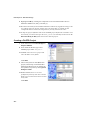
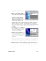
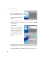
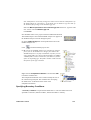
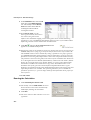
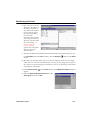
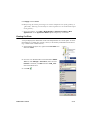
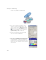
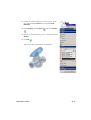
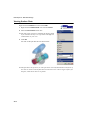
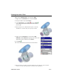
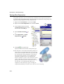
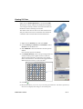
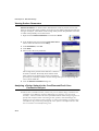
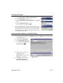
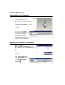
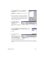
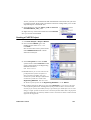
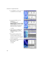
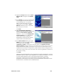
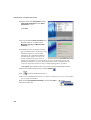
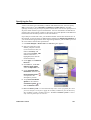
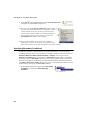
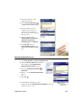
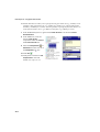
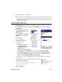
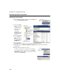
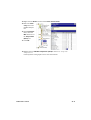
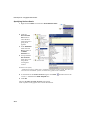
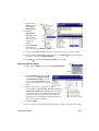
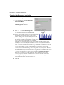
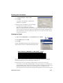
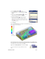
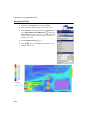
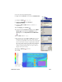
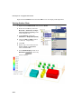
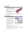
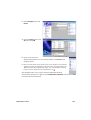
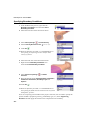
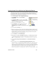
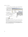
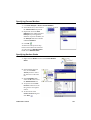
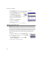
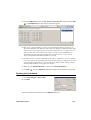
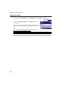
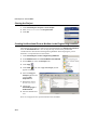
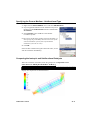
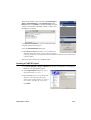
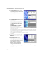
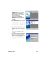
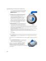
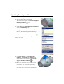
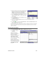
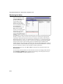
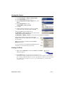
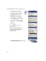
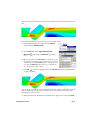
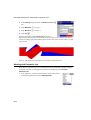
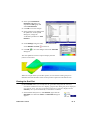
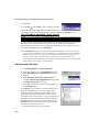
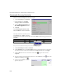
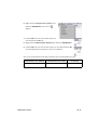
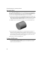
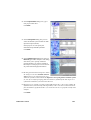
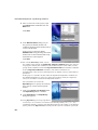
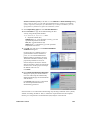
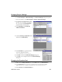
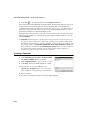
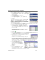
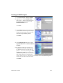
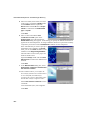
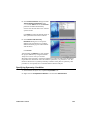
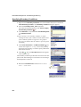
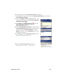
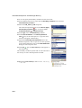
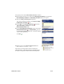
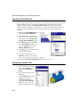
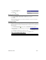
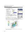
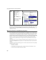
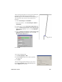
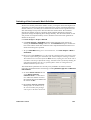
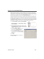
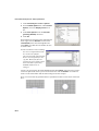
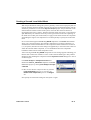
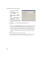
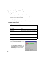
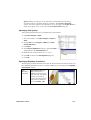
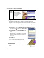
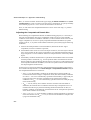
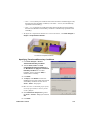
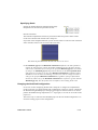
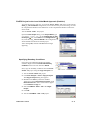
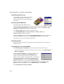
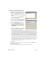
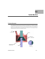
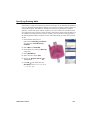
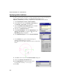
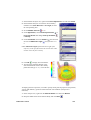
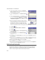
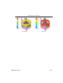
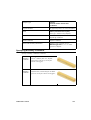
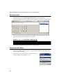
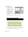
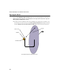
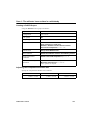
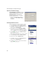
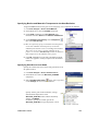
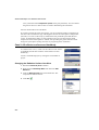
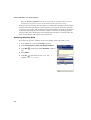
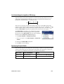
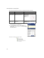
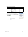
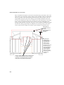
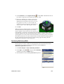
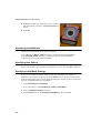
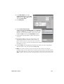
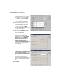
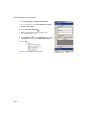
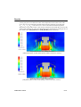
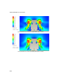
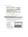
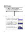
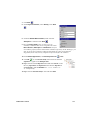
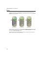
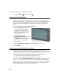
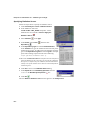
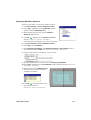
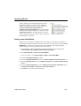
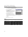
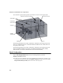
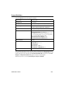
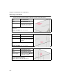
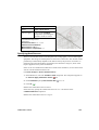
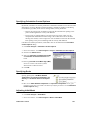
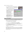
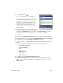
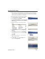
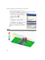
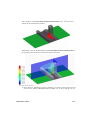
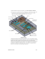
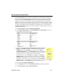
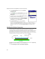
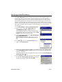
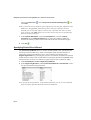
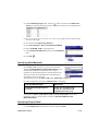
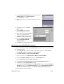
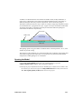
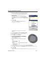
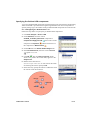
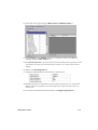
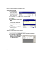
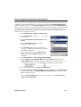
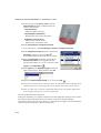
Specifying Local Initial Mesh Settings To apply the local mesh setting to a region we need a component representing this region to be disabled in the Component Control dialog box. 1 Click Flow Analysis > Insert > Local Initial Mesh. In Creo Parametric click Flow Analysis > Mesh > Local Initial Mesh. 2 In the Model Tree, select the LocalMesh component. 3 Click the Disable solid components check box. 4 Clear the Automatic settings check box. 5 Go to the Narrow Channels tab and set the Characteristic number of cells across a narrow channel = 2 and Narrow channels refinement level = 4. The Narrow Channels term is conventional and used for the definition of the model’s flow passages in the normal-to-solid/fluidinterface direction. The procedure of refinement is applied to each flow passage within the computational domain unless you specify for FloEFD to ignore the passages of a specified height with the Enable the minimum height of narrow channels and Enable the maximum height of narrow channels options. The Characteristic number of cells across a narrow channel (let us denote it as Nc) and Narrow channels refinement level (let us denote it as L) both influence the mesh in narrow channels in the following way: the basic mesh in narrow channels will be split to have the specified Nc number per a channel, if the resulting cells satisfy the specified L. In other words, whatever the specified Nc, a narrow channel’s cells cannot be smaller in 8L (2L in each direction of the Global Coordinate System) times than the basic mesh cell. This is necessary to avoid the undesirable mesh splitting in superfine channels that may cause increasing the number of cells to an excessive value. 6 Click OK. In our case, to ensure the 2 cells across a channel criterion, we increased the Narrow channels refinement level to 4. We perform these settings for both of the heat sinks under consideration. FloEFD FEP13 Tutorial C1-15