1
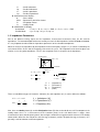
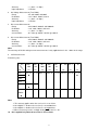
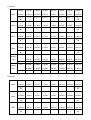
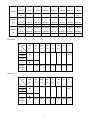
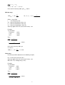
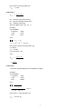
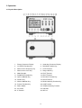
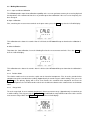
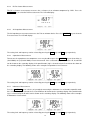
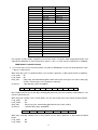
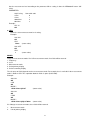
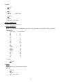
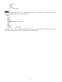
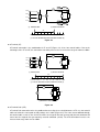
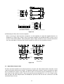
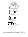
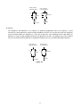
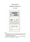
Contents 1. INTRODUCTION ...................................................................................................................................................................... 1 1.1 GENERAL ...................................................................................................................................................................................................... 1 1.2 IMPEDANCE PARAMETERS .............................................................................................................................................................................. 2 1.3 SPECIFICATION .............................................................................................................................................................................................. 3 1.4 ACCESSORIES ............................................................................................................................................................................................. 11 2. OPERATION ........................................................................................................................................................................... 12 2.1 PHYSICAL DESCRIPTION .............................................................................................................................................................................. 12 2.2 MAKING MEASUREMENT .............................................................................................................................................................................. 13 3. 2.2.1 Open and Short Calibration ........................................................................................................................................................... 13 2.2.2 Relative Mode ................................................................................................................................................................................ 13 2.2.3 Range Hold..................................................................................................................................................................................... 13 2.2.4 DC Resistance Measurement ........................................................................................................................................................ 14 2.2.5 AC Impedance Measurement ........................................................................................................................................................ 14 2.2.6 Capacitance Measurement ............................................................................................................................................................ 14 2.2.7 Inductance Measurement .............................................................................................................................................................. 14 OPERATION MODES............................................................................................................................................................. 15 3.1 REMOTE MODE COMMAND SYNTAX.............................................................................................................................................................. 18 3.2 REMOTE MODE COMMANDS......................................................................................................................................................................... 18 4. APPLICATION ........................................................................................................................................................................ 24 4.1 TEST LEADS CONNECTION ........................................................................................................................................................................... 24 4.2 OPEN/SHORT COMPENSATION ..................................................................................................................................................................... 26 4.3 SELECTING THE SERIES OR PARALLEL MODE................................................................................................................................................ 27 5. LIMITED ONE-YEAR WARRANTY ........................................................................................................................................ 29 6. SAFETY PRECAUTION ......................................................................................................................................................... 30 1. Introduction 1.1 General The Motech Industries MT4090 Synthesized In-Circuit LCR/ESR Meter is a high accuracy test instrument used for measuring inductors, capacitors and resistors with a basic accuracy of 0.1%. Also, with the built-in functions of DC/AC Voltage/Current measurements and Diode/Audible Continuity checks, the MT4090 can not only help engineers and students to understand the characteristics of electronics components but also being an essential tool on any service bench. The MT4090 is defaulted to auto ranging. However, it can be set to auto or manual ranging by pressing the Range Hold key. When LCR measurement mode is selected, one of the test frequencies, 100 Hz, 120 Hz, 1 KHz, 10 KHz, 100 KHz or 200 KHz, may be selected on all applicable ranges. One of the test voltages, 50mVrms, 0.25 Vrms, 1 Vrms or 1 VDC (DCR only), may also be selected on all applicable ranges. The dual display feature permits simultaneous measurements. When DC/AC voltage/current measurement mode or the Diode/Audible Continuity Check mode is selected, only the secondary display will be used to show the result of the measurement. The highly versatile MT4090 can perform virtually all the functions of most bench type LCR bridges. With a basic accuracy of 0.1%, this economical LCR meter may be adequately substituted for a more expensive LCR bridge in many situations. Also, with the basic accuracy of 0.4% in voltage and current measurements, the MT4090 performs the functions of a general purpose Digital Multi-Meter and can be used to replace the DMM on a service bench. The MT4090 has applications in electronic engineering labs, production facilities, service shops, and schools. It can be used to check ESR values of capacitors, sort and/or select components, measure unmarked and unknown components, and measure capacitance, inductance, or resistance of cables, switches, circuit board foils, etc. The key features are as following: 1. Voltage Measurements: AC : True RMS, up to 600Vrms @ 40 ~ 1K Hz DC : up to 600V Input Impedance : 1M-Ohm 2. Current Measurements: AC : True RMS, up to 2Arms @ 40 ~ 1K Hz DC : up to 2A Current Shunt : 0.1 Ohm @ > 20mA; 10 Ohm @ ≤ 20mA 3. Diode/Audible Continuity Checks: Open Circuit Voltage: 5Vdc Short Circuit Current: 2.5mA Beep On: ≤ 25 Ω Beep Off: ≥ 50 Ω 4. LCR Measurements: Test conditions 1 Frequency : 100Hz / 120Hz / 1KHz / 10KHz / 100KHz / 200KHz 2. Level : 1Vrms / 0.25Vrms / 50mVrms / 1VDC (DCR only) Measurement Parameters : Z, Ls, Lp, Cs, Cp, DCR, ESR, D, Q and θ Basic Accuracy : 0.1% Dual Liquid Crystal Display Auto Range or Range Hold USB Interface Communication Open/Short Calibration Primary Parameters Display: Z : AC Impedance DCR : DC Resistance 1 Ls : Serial Inductance Lp : Parallel Inductance Cs : Serial Capacitance Cp : Parallel Capacitance Second Parameter Display: θ : Phase Angle ESR : Equivalence Serial Resistance D : Dissipation Factor Q : Quality Factor Combinations of Display: Serial Mode : Z –θ, Cs – D, Cs – Q, Cs – ESR, Ls – D, Ls – Q, Ls – ESR Parallel Mode : Cp – D, Cp – Q, Lp – D, Lp – Q 1.2 Impedance Parameters Due to the different testing signals on the impedance measurement instrument, there are DC and AC impedances. The common digital multi-meter can only measure the DC impedance, but the MT4090 can do both. It is very important to understand the impedance parameters of the electronic components. When we analysis the impedance by the impedance measurement plane (Figure 1.1), it can be visualized by the real element on the X-axis and the imaginary element on the y-axis. This impedance measurement plane can also be seen as the polar coordinates. The Z is the magnitude and θ is the phase of the impedance. Imaginary Axis X Z (R s , X s ) s Z θ Rs Real Axis Figure 1.1 Z = R s + jX s = Z ∠ θ (Ω ) R s = Z Cos θ Z = Rs 2 + X s 2 X θ = Tan −1 s Rs X s = Z Sin θ Z Rs Xs Ω = = = = (Impedance) (Resistance) (Reactance) (Ohm) There are two different types of reactance: Inductive (XL) and Capacitive (XC). It can be defined as follows: X L = ω L = 2π fL XC = 1 ωC = 1 2π fC L = Inductance (H) C = Capacitance (F) f = Frequency (Hz) Also, there are Quality factor (Q) and the Dissipation factor (D) that need to be discussed. For component, the Quality factor serves as a measurement of the reactance purity. In the real world, there is always some associated resistance that dissipates power, decreasing the amount of energy that can be recovered. The Quality factor can be defined as the ratio of the stored energy (reactance) and the dissipated energy (resistance). Q is generally used for inductors and D for capacitors. 2 1 1 = D tan δ Xs ω Ls 1 = = = ω C s Rs Rs Rs B = G Rp Rp = = = ωC pRp ωLp X p Q = There are two types of the circuit mode, the series mode and the parallel mode. See Figure 1.2 to find out the relationship of the series and parallel modes. Real and imaginary components are parallel Real and imaginary components are serial Rs Rp jXs Z = Rs + jX s jXp Y= G=1/Rp 1 1 + RP jX P Figure 1.2 1.3 Specification Display Range: Parameter Display Range Z 0.000 Ω to 500.0 MΩ L 0.030 µH to 9999 H C 0.003 pF to 80.00 mF DCR 0.000 Ω to 500.0 MΩ ESR 0.000 Ω to 9999 Ω D 0.000 to 9999 Q 0.000 to 9999 θ -180.0 ° to 180.0 ° Voltage/Current Measurements V 0.0 mV to +/- 600 V A 0.000 mA to +/- 2 A Accuracy (Ae): 1. DC Voltage Measurement: Range : 2V, 20V, 200V, and 600V Resolution : 1mV, 10mV, 100mV, and 1V 3 jB=1/jXp Y = G + jB Accuracy Input Impedance : +/- (0.4% + 3 digits) : 1 M-Ohm 2. AC Voltage Measurement (True RMS): Range : 2V, 20V, 200V, and 600V Resolution : 1mV, 10mV, 100mV, and 1V Accuracy : +/- (0.8% + 5 digits) Input Impedance : 1 M-Ohm 3. DC Current Measurement: Range : 2mA, 20mA, 200mA, and 2000mA Resolution : 1uA, 10uA, 100uA, and 1mA Accuracy : +/- (0.4% + 3 digits) Current Shunt : 0.1 Ohm @ >20mA, 10 Ohm @ ≤20mA 4. AC Current Measurement (True RMS): Range : 2mA, 20mA, 200mA, and 2000mA Resolution : 1uA, 10uA, 100uA, and 1mA Accuracy : +/- (0.8% + 5 digits) Current Shunt : 0.1 Ohm @ >20mA, 10 Ohm @ ≤20mA Note: The accuracy of DC/AC voltage/current measurements is only applied when in 5% - 100% of the range. 5. LCR Measurement: Z Accuracy (Ae): |Zx| Freq. DCR 100Hz 20M ~ 10M ~ 1M ~ 100K ~ 10M 1M 100K 10K 1K (Ω) (Ω) (Ω) (Ω) (Ω) 2% 10K ~ 1K ~ 100 100 ~ 1 1 ~ 0.1 (Ω) (Ω) (Ω) ±1 1% ±1 0.5% ±1 0.2% ±1 0.1% ±1 0.2% ±1 0.5% ±1 1% ±1 120Hz 1KHz 10KHz 5% ±1 2% ±1 100KHz NA 5% ±1 2% ±1 1% ±1 0.4% ±1 1% ±1 200KHz Note: 1. The accuracy applies when the test level is set to 1Vrms. 2. Ae multiplies 1.25 when the test level is set to 250mVrms. 3. Ae multiplies 1.50 when the test level is set to 50mVrms. 4. When measuring L and C, multiply Ae by 1+ Dx 2 if the Dx0.1. : Ae is applied only when the test level is set to 1Vrms. 4 2% ±1 5% ±1 C Accuracy: 79.57pF | 159.1pF 159.1pF | 1.591nF 1.591nF | 15.91nF 15.91nF | 159.1uF 159.1nF | 1.591uF 1.591uF | 15.91uF 15.91uF | 1591uF 1591uF | 15.91mF 2% ± 1 1% ± 1 0.5% ± 1 0.2% ± 1 0.1% ± 1 0.2% ± 1 0.5% ± 1 1% ± 1 120Hz 66.31pF | 132.6pF 132.6pF | 1.326nF 1% ± 1 1.326nF | 13.26nF 0.5% ± 1 13.26nF | 132.6nF 0.2% ± 1 132.6nF | 1.326uF 0.1% ± 1 1.326uF | 13.26uF 0.2% ± 1 13.26uF | 1326uF 0.5% ± 1 1326uF | 13.26mF 1KHz 7.957pF | 15.91pF 15.91pF | 159.1pF 1% ± 1 159.1pF | 1.591nF 0.5% ± 1 1.591nF | 15.91nF 0.2% ± 1 15.91nF | 159.1nF 0.1% ± 1 159.1nF | 1.591uF 0.2% ± 1 1.591uF | 159.1uF 0.5% ± 1 159.1uF | 1.591mF 0.795pF 1.591pF 15.91pF 159.1pF 1.591nF 15.91nF 159.1nF 15.91uF | 1.591pF | 15.91pF 2% ± 1 | 159.1pF 0.5% ± 1 | 1.591nF 0.2% ± 1 | 15.91nF 0.1% ± 1 | 159.1nF 0.2% ± 1 | 15.91uF 0.5% ± 1 | 159.1uF NA 0.159pF | 1.591pF 5% ± 1 1.591pF | 15.91pF 2%± 1 15.91pF | 159.1pF 1%± 1 159.1pF | 1.591nF 0.4%± 1 1.591nF | 15.91nF 1%± 1 15.91nF | 1.591uF 2%± 1 1.591uF | 15.91uF 5% ± 1 0.079pF | 0.795pF 5% ± 1 0.795pF | 7.957pF 2%± 1 7.957pF | 79.57pF 1%± 1 79.57pF | 795.7pF 0.4%± 1 795.7pF | 7.957nF 1%± 1 7.957nF | 795.7nF 2%± 1 795.7nF | 7.957uF 5% ± 1 100Hz 31.83KH | 15.91KH 15.91KH | 1591H 1% ± 1 1591H | 159.1H 0.5% ± 1 159.1H | 15.91H 0.2% ± 1 15.91H | 1.591H 0.1% ± 1 1.591H | 159.1mH 0.2% ± 1 159.1mH | 1.591mH 0.5% ± 1 1.591mH | 159.1uH 120Hz 26.52KH | 13.26KH 13.26KH | 1326H 1% ± 1 1326H | 132.6H 0.5% ± 1 132.6H | 13.26H 0.2% ± 1 13.26H | 1.326H 0.1% ± 1 1.326H | 132.6mH 0.2% ± 1 132.6mH | 1.326mH 0.5% ± 1 1.326mH | 132.6uH 3.183KH 1.591KH | 159.1H 1% ± 1 159.1H | 15.91H 0.5% ± 1 15.91H | 1.591H 0.2% ± 1 1.591H | 159.1mH 159.1mH | 15.91mH 15.91mH | 159.1uH 159.1uH | 15.91uH 100Hz 10KHz 2% ± 1 2% ± 1 5% ± 1 100KHz 200KHz NA NA NA 1% ± 1 1% ± 1 1% ± 1 L Accuracy: 1KHz 2% ± 1 2% ± 1 | 1.591KH 2% ± 1 5 0.1% ± 1 0.2% ± 1 0.5% ±1 1% ± 1 1% ± 1 1% ± 1 10KHz 100KHz 200KHz 318.3H | 159.1H 159.1H | 15.91H 2% ± 1 15.91H | 1.591H 0.5% ± 1 1.591H | 159.1mH 0.2% ± 1 159.1mH | 15.91mH 0.1% ± 1 15.91mH | 1.591mH 0.2% ± 1 1.591mH | 15.91uH 0.5% ± 1 15.91uH | 1.591uH 31.83H | 15.91H NA 15.91H | 1.591H 5% ± 1 1.591H | 159.1mH 2%± 1 159.1mH | 15.91mH 1% ± 1 15.91mH | 1.591mH 0.4% ± 1 1.591mH | 159.1uH 1% ± 1 159.1uH | 1.591uH 2%± 1 1.591uH | 0.159uH 5% ± 1 15.91H | 7.957H NA 7.957H | 795.7mH 5% ± 1 795.7mH | 79.57mH 2%± 1 79.57mH | 7.957mH 1% ± 1 7.957mH | 795.7uH 0.4% ± 1 795.7uH | 79.57uH 1% ± 1 79.57uH | 0.795uH 2%± 1 0.795uH | 0.079uH 5% ± 1 5% ± 1 D Accuracy: |Zx| 20M ~ 10M ~ 1M ~ 100K ~ 10K ~ 1K ~ 100 ~ 1 1 ~ 0.1 10M 1M 100K 10K 1K 100 (Ω) (Ω) (Ω) (Ω) (Ω) (Ω) (Ω) (Ω) Freq. 100Hz ±0.020 ±0.010 ±0.005 ±0.002 ±0.002 ±0.002 ±0.005 ±0.010 10KHz ±0.050 ±0.020 100KHz NA 120Hz 1KHz ±0.050 ±0.020 ±0.010 ±0.004 ±0.010 ±0.020 ±0.050 200KHz θ Accuracy: |Zx| 20M ~ 10M ~ 1M ~ 100K ~ 10K ~ 10M 1M 100K 10K 1K 100 (Ω) (Ω) (Ω) (Ω) (Ω) (Ω) 1K ~ 100 ~ 1 1 ~ 0.1 (Ω) (Ω) Freq. 100Hz ±1.046 ±0.523 ±0.261 ±0.105 ±0.105 ±0.105 ±0.261 ±0.523 10KHz ±2.615 ±1.046 100KHz NA 120Hz 1KHz ±2.615 ±1.046 ±0.409 ±0.209 ±0.409 ±1.046 ±2.615 200KHz 6 1% ± 1 Z Accuracy: As shown in Z accuracy table. C Accuracy: As shown in C accuracy table or could be calculated as the following example. Zx = 1 2 ⋅ π ⋅ f ⋅ Cx CAe = Ae of C f : Test Frequency (Hz) Cx : Measured Capacitance Value (F) |Zx| : Measured Impedance Value (Ω) Accuracy applies when Dx (measured D value) ≤ 0.1 When Dx > 0.1, multiply CAe by Example: Test Condition: Frequency : Level : DUT : 1 + Dx 2 1KHz 1Vrms 100nF Then 1 2 ⋅ π ⋅ f ⋅ Cx 1 = = 1590 Ω 3 2 ⋅ π ⋅ 10 ⋅ 100 ⋅ 10 − 9 Zx = Refer to the Z accuracy table, get CAe=±0.1% L Accuracy: As shown in L accuracy table or could be calculated as the following example. Zx = 2 ⋅ π ⋅ f ⋅ Lx LAe = Ae of L f : Test Frequency (Hz) Lx : Measured Inductance Value (H) |Zx| : Measured Impedance Value (Ω) Accuracy applies when Dx (measured D value) ≤ 0.1 When Dx > 0.1, multiply LAe by 1 + Dx 2 Example: Test Condition: Frequency : 1KHz Level : 1Vrms DUT : 1mH Then 7 Zx = 2 ⋅ π ⋅ f ⋅ Lx = 2 ⋅ π ⋅ 10 3 ⋅ 10 − 3 = 6 . 283 Ω Refer to the Z accuracy table, get LAe = ±0.5% ESR Accuracy: ESR Ae = ± Xx ⋅ Ae 100 Xx = 2 ⋅ π ⋅ f ⋅ Lx = 1 2 ⋅ π ⋅ f ⋅ Cx ESRAe = Ae of ESR f : Test Frequency (Hz) Xx : Measured Reactance Value (Ω) Lx : Measured Inductance Value (H) Cx : Measured Capacitance Value (F) Accuracy applies when Dx (measured D value) ≤ 0.1 Example: Test Condition: Frequency : 1KHz Level : 1Vrms DUT : 100nF Then 1 2 ⋅ π ⋅ f ⋅ Cx 1 = = 1590 Ω 3 2 ⋅ π ⋅ 10 ⋅ 100 ⋅ 10 − 9 Zx = Refer to the accuracy table, get CAe=±0.1%, ESR Ae = ± Xx ⋅ Ae = ±1.59 Ω 100 D Accuracy: D accuracy could be obtained as the following example. DAe = Ae of D measurement value Accuracy applies when Dx (measured D value) ≤ 0.1 When Dx > 0.1, multiply Dx by (1+Dx) Example: Test Condition: Frequency : 1KHz Level : 1Vrms DUT : 100nF Then 1 2 ⋅ π ⋅ f ⋅ Cx 1 = 1590 Ω = 3 2 ⋅ π ⋅ 10 ⋅ 100 ⋅ 10 − 9 Zx = 8 Refer to the D accuracy table, get D Ae = ± 0 . 002 Q Accuracy: Q Ae = ± Qx 2 ⋅ De 1 m Qx ⋅ De QAe = Ae of Q measurement value Qx : Measured Quality Factor Value De : Relative D Accuracy Accuracy applies when Qx ⋅ De < 1 Example: Test Condition: Frequency : 1KHz Level : 1Vrms DUT : 1mH Then Zx = 2 ⋅ π ⋅ f ⋅ Lx = 2 ⋅ π ⋅ 10 3 ⋅ 10 − 3 = 6 .283 Ω Refer to the L and D accuracy tables, get LAe=±0.5%, De = ± 0 . 005 If measured Qx = 20 Then Q Ae = ± =± Qx 2 ⋅ De 1 m Qx ⋅ De 2 1 m 0 .1 θ Accuracy: θ accuracy could be obtained as the following example. Example: Test Condition: Frequency : 1KHz Level : 1Vrms DUT : 100nF Then 1 2 ⋅ π ⋅ f ⋅ Cx 1 = 1590 Ω = 3 2 ⋅ π ⋅ 10 ⋅ 100 ⋅ 10 − 9 Zx = Refer to the θ accuracy table, get θ Ae = ± 0 . 105 deg 9 Testing Signal: Level Accuracy Frequency Accuracy Output Impedance General: Temperature Relative Humidity AC Power Dimensions Weight : ± 10% : 0.1% : 100Ω ± 5% : 0°C to 40°C (Operating) -20°C to 70°C (Storage) : Up to 85% : 110/220V, 60/50Hz : 300mm x 220mm x 150mm (L x W x H) 11.8” x 8.7” x 5.9” : 4500g Considerations When LCR measurement mode is selected, the following factors shall be considered. Test Frequency The test frequency is user selectable and can be changed. Generally, a 1 KHz test signal or higher is used to measure capacitors that are 0.01uF or smaller and a 120Hz test signal is used for capacitors that are 10uF or larger. Typically a 1 KHz test signal or higher is used to measure inductors that are used in audio and RF (radio frequency) circuits. This is because these kinds of inductors operate at higher frequencies and require that they shall be measured at a higher frequency. Generally, inductors with inductances below 2mH should be measured at test frequency of 1 KHz or higher and inductors above 200H should be measured at 120Hz or lower. It is best to check with the component manufacturers’ data sheet to determine the best test frequency for the device. Charged Capacitors Always discharge any capacitor prior to making a measurement since a charged capacitor may seriously damage the meter. Effect Of High D on Accuracy A low D (Dissipation Factor) reading is desirable. Electrolytic capacitors inherently have a higher dissipation factor due to their normally high internal leakage characteristics. If the D (Dissipation Factor) is excessive, the capacitance measurement accuracy may be degraded. It is best to check with the component manufacturers’ data sheet to determine the desirable D value of a good component. Measuring Capacitance of Cables, Switches or Other Parts Measuring the capacitance of coaxial cables is very useful in determining the actual length of the cable. Most manufacturer specifications list the amount of capacitance per foot of cable and therefore the length of the cable can be determined by measuring the capacitance of that cable. For example: A manufacturers, specification calls out a certain cable, to have a capacitance of 10 pF per foot, After measuring the cable, a capacitance reading of 1.000 nF is displayed. Dividing 1000pF (1.000 nF) by 10 pF per foot yields the length of the cable to be approximately 100 feet. Even if the manufacturers’ specification is not known, the capacitance of a measured length of cable (such as 10 feet) can be used to determine the capacitance per foot. Do not use too short length such as one foot, because any error becomes magnified in the total length calculations. Sometimes, the affecting stray capacitance of switches, interconnect cables, circuit board foils, or other parts, could be critical to circuit design, or must be repeatable from one unit to another. Series Vs Parallel Measurement (for Inductors) The series mode displays the more accurate measurement in most cases. The series equivalent mode is essential for obtaining an accurate Q reading of low Q inductors. Where ohmic losses are most significant, the series equivalent mode is preferred. However, there are cases 10 where the parallel equivalent mode may be more appropriate. For iron core inductors operating at higher frequencies where hysteresis and eddy currents become significant, measurement in the parallel equivalent mode is preferred. 1.4 Accessories Operating Manual AC Power Cord Kelvin Clip DMM Test Leads 1 pc 1 pc 1 pc 1 pc 11 2. Operation 2.1 Physical Description 1. Primary Parameter Display 2. Secondary Parameter Display 3. L/C/Z/DCR Function Key 4. DCA/ACA Function Key 5. Measurement Frequency Key 6. LCUR Terminal 7. Measurement Level Key 8. Range Hold Key 9. Model Number 10. LPOT Terminal 11. D/Q/θ/ESR Function Key 12. HPOT Terminal 13. Open Calibration Key 14. DCV/ACV Function Key 15. Relative Key 16. HCUR Terminal 17. Short Calibration Key 18. Diode/Continuity Function Key 19. Remote Function Key 20. COM Terminal 21. Power Switch 22. V/Diode/Continuity Terminal 23. AC Power 24. USB Port 25. A Terminal 26. 2A Fuse 12 2.2 Making Measurement 2.2.1 Open and Short Calibration The MT4090 provides open/short calibration capability so the user can get better accuracy in measuring high and low impedance. We recommend that the user perform open/short calibration if the test level or frequency has been changed. Open Calibration First, remaining the measurement terminals at the open status, press the Open key then the LCD will display: This calibration takes about 15 seconds. After it is finished, the MT4090 will beep to show that the calibration is done. Short Calibration To perform the short calibration, insert the Shorting Bar into the measurement terminals. Press the Short key then the LCD will display: This calibration takes about 15 seconds. After it is finished, the MT4090 will beep to show that the calibration is done. 2.2.2 Relative Mode The relative mode lets the user to make a quick sort of a bunch of components. First, insert the standard value component to get the standard value reading. (Approximately 5 seconds to get a stable reading.) Then, press the Relative key, the primary display will reset to zero. Remove the standard value component and insert the unknown component, the LCD will show the value that is the difference between the standard value and unknown value. 2.2.3 Range Hold To set the range hold, insert a standard component in that measurement range. (Approximately 5 seconds to get a stable reading.) Then, by pressing the Range Hold key it will hold the range within 0.5 to 2 times of the current measurement range. When the Range Hold is pressed, the LCD will display: 13 2.2.4 DC Resistance Measurement The DC resistance measurement measures the resistance of an unknown component by 1VDC. Press the L/C/Z/DCR key to select the DCR measurement. The LCD will display: 2.2.5 AC Impedance Measurement The AC impedance measurement measures the Z of an unknown device. Press the L/C/Z/DCR key to select the Z measurement. The LCD will display: The testing level and frequency can be selected by pressing the Level key and Freq key, respectively. 2.2.6 Capacitance Measurement To measure the capacitance of a component, users may be able to press the L/C/Z/DCR key to select either Cs (Serial Mode) or Cp (Parallel Mode) measurement mode. If the serial mode (Cs) is selected, the D, Q and ESR can be shown on the secondary display. If the parallel mode (Cp) is selected, only the D and Q can be shown on the secondary display. The following shows some examples of capacitance measurement: The testing level and frequency can be selected by pressing the Level key and Freq key, respectively. 2.2.7 Inductance Measurement Press the L/C/Z/DCR key to select Ls or Lp mode for measuring the inductance in serial mode or parallel mode. If the serial mode (Ls) is selected, the D, Q and ESR can be shown on the secondary display. If the parallel mode (Lp) is selected, only the D and Q can be shown on the secondary display. The following shows some examples of inductance measurement: The testing level and frequency can be selected by pressing the Level key and Freq key, respectively. 14 3. Operation Modes There are four operation modes in the MT4090. They are Normal, Binning, Remote and Remote Binning modes. By pressing the Remote button, users can select one of the 4 operation modes above. Normal Mode: The Normal mode is the default operation mode when power on. It is a local mode that the MT4090 is controlled by the keypads and the results of the measurement will be sent to both LCD display and a remote USB equipped PC through the build-in USB port. Binning Mode: The Binning mode is reserved for future use (such as GPIB). Currently, it is set to work the same way as the Normal mode that receives commands from the keypads and sends the results of measurement to both LCD display and a remote PC through the USB port. Remote Binning Mode: In the Remote Binning mode, the “RMT Bin” on the LCD will be lit, the operation of MT4090 is controlled by a remote USB equipped PC or terminal, and the results of the measurement will be simultaneously sent to the local LCD display and remote workstation through the USB port. In this mode all functional keypads except Remote button are locked. Remote Binning mode is opened for users to design your own private, fast and high efficient application programs. Users can design a server or driver (any software component that can do server’s job) with Graphic interface, OSI network model, and powerful interpreter built in it to support Graphic display, Network connectivity, structure command (SCPI, IEEE488 etc.) interpretations, and let it be a bridge between a higher level application program such as VB, VISUAL C++, EXCEL, ACCESS etc. and the MT4090. It is described in the following figure. Server: COM, DCOM, ATL, CONTROL, Model 4090 AUTOMATION EXE VB, VISUAL Built in: C++, EXCEL, Graphic interface, ACCESS etc. OSI network model, and/or powerful Interpreter or Parser The communication protocol between the MT4090 and a remote USB equipped PC is described as follows. 1. The commands that will be sent from a remote PC to the MT4090 are used to set-up the machine to a selected measurement mode. The command syntax is: MOD current-state-code It always starts with MOD follows by a space and then the current state code. The current state code that is defined in the table below is 3 bytes (24 bits) long, bit-23, 22, 21… bit-0, where bit-23 is the MSB and bit-0 is the LSB. 15 bit position LCR DC/AC V/A Bit 2 – Bit 0 000 001 010 011 100 101 110 111 Bit 4 – Bit 3 00 01 10 11 Bit 5 0 1 Bit 6 0 1 Bit 7 0 1 Bit 10 – Bit 8 000 001 010 011 100 101 110 111 Bit 12 – Bit 11 00 01 10 11 Bit 16 – Bit 13 0000 0001 0010 0011 0100 0101 0110 0111 1000 1001 1010 1011 1100 (test freq) 100 Hz 120 Hz 1K Hz 10K Hz 100K Hz 200K Hz Reserved Reserved (test level) 50 mVrms 250 mVrms 1 Vrms Reserved Reserved Default Reserved Reserved Default Reserved Relative Normal Relative Normal Calibration Normal Calibration Normal Reserved Reserved Lp Ls Cp Cs Z DCR Reserved Reserved Reserved D Q DEG ESR RH nH RH uH RH mH RH H RH pF RH nF RH uF RH mF RH F RH Ohm RH K-Ohm RH M-Ohm Reserved 16 Reserved RH mV, mA RH V, A Reserved 1101 1110 1111 Bit 17 0 1 Auto-Ranging Auto-Ranging Short Cal Open Cal Short Cal Reserved Measurement Modes Reserved LCR DCV ACV Diode Continuity DCA ACA Reserved Reserved Bit 21 – Bit 18 0000 0001 0010 0011 0100 0101 0110 0111 Others Bit 23 – Bit 22 00 01 10 11 For example: if LCR function, Cp with D measurement mode is selected in Auto-ranging with Relative and Open/Short Calibration are turned off and test signal is 1 Vrms in 1 KHz, then the command is as following: MOD 000001111110001011010010 2. The results of the measurement that will be sent from the MT4090 to a remote PC will be packed in either 7-byte or 11-byte format. When dual data (such as Cp with D) will be sent, the data is packed in 11-byte format shown as following: Lead_code1 : 02 Lead_code2 : 09 Data_code : 8-byte long; two 32-bit floating point number format; the first 4-byte is the main reading (Cp) and the second 4-byte is the secondary reading (D) Checksum : -((02+09+data_code) && 0x00FF) 02 09 M-B0 M-B1 M-B2 M-B3 S-B0 S-B1 S-B2 S-B3 CS where M-Bx and S-Bx are the four bytes floating point format of main and secondary reading which is sent from the lowest byte first. When only main reading (such as DCR) will be sent, the data is packed in 7-byte format described below: Lead_code1 : 02 Lead_code2 : 03 Data_code : 4 bytes long; the 32-bit floating point format of the main reading Checksum : -((02+03+data_code) && 0x00FF) 02 03 M-B0 M-B1 M-B2 M-B3 CS When only secondary reading (such as DCV) will be sent, the data is packed in 11-byte format described below: Lead_code1 : 02 Lead_code2 : 09 17 Data_code Checksum : 8 bytes long; two 32-bit floating point format of the secondary reading : -((02+09+data_code) && 0x00FF) Remote Mode: 02 09 S-B0 S-B1 S-B2 S-B3 S-B0 S-B1 S-B2 S-B3 CS When in the Remote mode, the “RMT” on the LCD will be lit and the MT4090 is capable of communicating to remote USB equipped PC or terminal through the build-in USB port. The connection setting is as follow: Transmission Mode : Half Duplex Baud Rate : 9600 Parity Bit : None Data Bits : 8 Stop Bit : 1 Handshake : None In this mode, the LCD display and all keypads except the Remote button will be locked. And the external program through the USB port controls the operation of the MT4090. 3.1 Remote Mode Command Syntax The command syntax of Models 4090 is as following: COMMAND(?) (PARAMETER) The format of COMMAND and PARAMETER is as following: 1. There is at least one space between COMMAND and PARAMETER. 2. The PARAMETER should use only ASCII string not numerical code. 3. Value parameter can be integer, floating or exponent with the unit. For example: 50mV 0.05V 5.0e1mV 4. The question mark (?) at the end of COMMAND means a query or a measuring command. For example: “CpD” sets the measurement mode to Cp and D. “CpD?” sets the measurement mode to Cp and D as well as measures the values and send them back. 5. The COMMAND and PARAMETER can be either upper or lower case. But the unit to describe the value in the PARAMETER should have different between milli (m) and mega (M). For example: 1mV equals 0.001V. 1MV equals 1000000V. 6. The “end of command” character should be placed at the end. There are: ASCII CR (0DH) or ASCII LF (0AH) 3.2 Remote Mode Commands Measurement Setting (or Querying) Command The following measurement mode-setting and the query commands are supported in the MT4090. When a mode-setting command is entered the MT4090 will return “OK” follows the ASCII CR (0DH) and ASCII LF (0AH) after setting is complete. When query command is entered, the MT4090 will send back the values of measurement. After a command is entered, the meter shall respond within 2.5 seconds with the return values follow the ASCII CR and ASCII LF. If an illegal command is entered, there is no response from the meter. DCR(?) CpRp(?) CpQ(?) CpD(?) DC resistance measurement mode setting or querying command. Parallel capacitance and parallel resistance measurement mode setting or querying command. Parallel capacitance and quality factor measurement mode setting or querying command. Parallel capacitance and dissipation factor measurement mode setting or querying command. 18 CsRs(?) CsQ(?) CsD(?) LpRp(?) LpQ(?) LpD(?) LsRs(?) LsQ(?) LsD(?) RsXs(?) RpXp(?) ZTD(?) ZTR(?) DCV(?) ACV(?) DCA(?) ACA(?) Serial capacitance and serial resistance measurement mode setting or querying command. Serial capacitance and quality factor measurement mode setting or querying command. Serial capacitance and dissipation factor measurement mode setting or querying command. Parallel inductance and parallel resistance measurement mode setting or querying command. Parallel inductance and quality factor measurement mode setting or querying command. Parallel inductance and dissipation factor measurement mode setting or querying command. Serial inductance and serial resistance measurement mode setting or querying command. Serial inductance and quality factor measurement mode setting or querying command. Serial inductance and dissipation factor measurement mode setting or querying command. Serial resistance and serial reactance measurement mode setting or querying command. Parallel resistance and parallel reactance measurement mode setting or querying command. Impedance and angle (Deg) measurement mode setting or querying command. Impedance and angle (Rad) measurement mode setting or querying command. DC Voltage measurement mode setting or query command. AC Voltage measurement mode setting or query command. DC Current measurement mode setting or query command. AC Current measurement mode setting or query command. Example: CPD (set to Cp-D measurement mode) OK CPD? 0.22724 0.12840 (return values) DCR? 5.1029 (return value) *IDN? Query the identity of the MT4090. This command is used to identify the basic information of MT4090. The return value has three fields separated by comma (,). The total length will not greater than 100 characters. The fields are: Description of the meter Not defined Firmware Version Number Example: *IDN? 200KHz LCR Meter, 0,2.000 *RST Reset the MT4090 to the power on default status. The default status is: 1KHz 1Vrms CpD uF After the MT4090 is reset, it will return the identity string back. ASC Set the format of the return value. This command sets the ASCII string return or the numerical code. PARAMETER: ON ASCII string OFF Numerical code 19 Example: ASC ON OK (return) FREQ? 1KHz (return) ASC OFF OK (return) FREQ? 2 (return) CORR OPEN Perform the open calibration. This command sets the MT4090 to do the open calibration. After the calibration is done, the MT4090 will return the “OK” string back. CORR SHORT Perform the short calibration. This command sets the MT4090 to do the short calibration. After the calibration is done, the MT4090 will return the “OK” string back. FREQ(?) PARAMETER Set (query) the measurement frequency. FREQ PARAMETER Set the measurement frequency according to the parameter. When setting command is entered, the MT4090 will return “OK” string after setting is done. PARAMETER: ASCII string 100Hz 120Hz 1KHz 10KHz 100KHz 200KHz Numerical code 0 1 2 3 4 5 Example: FREQ 100KHz OK (return) FREQ? Return the current measurement frequency setting. Example: ASC ON OK FREQ? 1KHz (return value) ASC OFF OK FREQ? 2 (return value) LEV(?) PARAMETER Set (query) the measurement level. LEV PARAMETER 20 Set the measurement level according to the parameter. When setting is done the MT4090 will return “OK” string. PARAMETER: ASCII string 1VDC 1Vrms 250mVrms 50mVrms Numerical code 0 1 2 3 Example: LEV? LEV 1V OK Return the current measurement level setting. Example: ASC ON OK LEV? 1Vrms (return value) ASC OFF OK LEV? 1 (return value) MODE? Query the measurement mode. If in LCR measurement mode, five fields will be returned. 1. 2. 3. 4. 5. Frequency Level Measurement mode Unit of primary display Unit of secondary display The existence of field 5 depends on the measurement mode. For example, there’s no field 5 if the measurement mode is DCR or CPD. The separation between fields is space (ASCII 20H). Example: ASC ON OK CPD OK MODE? 1KHz 1Vrms CpD uF (return value) ASC ON OK CPRP OK MODE? 1KHz 1Vrms CpRp uF Ohm (return value) If in Voltage measurement mode, three fields will be returned. 1. 2. Measurement mode Unit of primary display 21 Example: ASC ON OK DCV OK MODE? DCV V (return value) RANG mV OK MODE? DCV mV (return value) RANG(?) PARAMETER Set (query) the measurement unit. RANG PARAMETER Set the measurement unit according to the parameter. “OK” string will be returned when setting is complete. PARAMETER: ASCII string pF nF uF mF F nH uH mH H KH mOhm Ohm KOhm MOhm mV V mA A Numerical code 0 1 2 3 4 8 9 10 11 12 17 18 19 20 21 22 23 24 Example: RANG pF OK RANG? Return the current measurement unit setting. Example: ASC ON OK RANG? pF (return value) 22 ASC OFF OK RANG? 0 (return value) READ? Return the measurement value. This command will perform a measurement according to the current measurement mode and return the measured value. Example: CPD OK READ? 0.22724 0.12840 (return value) DCR OK READ? 5.1029 (return value) The “DCR”, “DCV”, and “ACV” measurements will send only one measured value. The other measurement modes will send two measured values separated by space (ASCII 20H). 23 4. Application 4.1 Test Leads Connection Auto balancing bridge has four terminals (HCUR, HPOT, LCUR and LPOT) to connect to the device under test (DUT). It is important to understand what connection method will affect the measurement accuracy. 2-Terminal (2T) 2-Terminal is the easiest way to connect the DUT, but it contents many errors that are the inductance and resistance as well as the parasitic capacitance of the test leads (Figure 4.1). Due to these errors in measurement, the effective impedance measurement range will be limited at 100Ω to 10KΩ. Ro Lo A HCUR HPOT Co V DUT LPOT DUT LCUR Ro (a) CONNECTION Lo (b) BLOCK DIAGRAM 2T 1m 10m 100m 1 10 100 1K 10K 100K 1M 10M (c) TYPICAL IMPEDANCE MEASUREMENT RANGE( Ω ) Figure 4.1 3-Terminal (3T) 3-Terminal uses coaxial cable to reduce the effect of the parasitic capacitor (Figure 4.2). The shield of the coaxial cable should connect to guard of the instrument to increase the measurement range up to 10MΩ. Ro Lo A H CUR HPOT Co V DUT DUT Co doesn' t effect measurement result LPOT LCUR Ro (a) CONNECTION Lo (b) BLOCK DIAGRAM 3T 1m 10m 100m 1 10 100 1K 10K 100K 1M 10M (c) TYPICAL IMPEDANCE MEASUREMENT RANGE(Ω) A V DUT (d) 2T CONNECTION WITH SHILDING 4-Terminal (4T) Figure 4.2 4-Terminal connection reduces the effect of the test lead resistance (Figure 4.3). This connection can improve the measurement range down to 10mΩ. However, the effect of the test lead inductance can’t be eliminated. 24 A HCUR HPOT DUT V DUT LPOT LCUR (a) CONNECTION (b) BLOCK DIAGRAM 4T 1m 10m 100m 1 10 100 1K 10K 100K 1M 10M (c) TYPICAL IMPEDANCE MEASUREMENT RANGE (Ω) Figure 4.3 5-Terminal (5T) 5-Terminal connection is the combination of 3T and 4T (Figure 4.4). It has four coaxial cables. Due to the advantage of the 3T and 4T, this connection can widely increase the measurement range for 10mΩ to 10MΩ. A HCUR HPOT DUT V DUT LPOT L CUR (a) CONNECTION (b) BLOCK DIAGRAM 5T 1m 10m 100m 1 10 100 1K 10K 100K 1M 10M (c) TYPICAL IMPEDANCE MEASUREMENT RANGE (Ω) A V DUT (d) WRONG 4T CONNECTION 4-Terminal Path (4TP) Figure 4.4 4-Terminal Path connection solves the problem that caused by the test lead inductance. 4TP uses four coaxial cables to isolate the current path and the voltage sense cable (Figure 4.5). The return current will flow through the coaxial cable as well as the shield. Therefore, the magnetic flux that generated by internal conductor will cancel out the magnetic flux generated by external conductor (shield). The 4TP connection increases the measurement range from 1mΩ to 10MΩ. 25 HCUR V HPOT DUT DUT LPOT LCUR A (a) CONNECTION (b) BLOCK DIAGRAM HCUR HPOT 4T DUT LPOT 1m 10m100m 1 10 100 1K 10K 100K 1M 10M (c) TYPICAL IMPEDANCE MEASUREMENT RANGE(Ω) LCUR (d) 4T CONNECTION WITH SHILDING Figure 4.5 Eliminating the Effect of the Parasitic Capacitor When measuring the high impedance component (i.e. low capacitor), the parasitic capacitor becomes an important issue (Figure 4.6). In figure 4.6(a), the parasitic capacitor Cd is paralleled to DUT as well as the Ci and Ch. To correct this problem, add a guard plane (Figure 4.6(b)) in between H and L terminals to break the Cd. If the guard plane is connected to instrument guard, the effect of Ci and Ch will be removed. HCUR HPOT LPOT LCUR Cd HPOT LPOT LCUR Guard Plant DUT Ch HCUR Connection Point Cl Ground (b) Guard Plant reduces Parastic Effect (a) Parastic Effect Figure 4.6 4.2 Open/Short Compensation For those precision impedance-measuring instruments, the open and short compensation need to be used to reduce the parasitic effect of the test fixture. The parasitic effect of the test fixture can be treated like the simple passive components in figure 4.7(a). When the DUT is open, the instrument gets the conductance Yp = Gp + jωCp (Figure 4.7(b)). When the DUT is short, the instrument gets the impedance Zs = Rs + jωLs (Figure 4.7(c)). After the open and short compensation, the MT4090 has Yp and Zs that can then be used for the real Zdut calculation (Figure 4.7(d)). 26 Parastic of the Test Fixture Redundant (Zs) Impedance HCUR Rs Parastic (Yo) Conductance Ls HPOT Zm LCUR Zdut Go Co LPOT (a) Parastic Effect of the Test Fixture HCUR Rs Ls HPOT Yo Co LPOT Go OPEN Yo = Go + jω Co 1 ) (Rs + jω<< G o+jω Co LCUR (b) OPEN Measurement HCUR Rs Ls HPOT Zs Co LPOT LCUR Go SHORT Zs = Rs + jω Ls (c) SHORT Measurement Zs Zm Yo Zdut Zm - Zs Zdut = 1-(Zm-Zs)Yo (d) Compensation Equation Figure 4.7 4.3 Selecting the Series or Parallel Mode According to different measuring requirement, there are series and parallel modes to describe the measurement results. It is depending on the high or low impedance value to decide what mode to be used. Capacitor The impedance and capacitance in the capacitor are negatively proportional. Therefore, the larger capacitance means the lower impedance, the smaller capacitance means the higher impedance. Figure 4.8 shows the equivalent circuit of capacitor. If the capacitance is small, the Rp is more important than the Rs. If the capacitance is large, the Rs shouldn’t be avoided. Hence, it is properly to use parallel mode for low capacitance measurement and series mode for high capacitance measurement. 27 Small capacitor (High impedance) C Large capacitor (Low impedance) C RP RP No Effect Effect RS RS No Effect Effect Inductor The impedance and inductance of a inductor are positively proportional when test frequency is fixed. Therefore, the larger inductance equals to higher impedance and vice versa. Figure 4.9 shows the equivalent circuit of inductor. When the inductance is small, the Rs becomes more important than the Rp. When the inductance is large, the Rp should be taking into consideration. Therefore, it is properly using series mode to measure an inductor with low inductance and parallel mode to measure an inductor with high inductance. Large inductor (High impedance) Small inductor (Low impedance) L L RP RP No Effect Effect RS RS No Effect Effect Figure 4.9 28 5. Limited ONE-Year Warranty Motech Industries Incorporation warrants to the original purchaser that its product and the component parts thereof, will be free from defects in workmanship and materials for a period of one year form the date of purchase. Motech Industries Incorporation will, without charge, repair or replace, at its option, defective product or component parts. Return product must be accompanied by proof of the purchase date in the form and the sales receipt. Exclusions: this warranty does not apply in the event of misuse or abuse of the product or as a result of unauthorized alternations or repairs. It is void if the serial number is alternated, defaced or removed. Motech Industries Incorporation shall not be liable for any consequential damages, including without limitation damages resulting from loss of use. This warranty gives you specific rights and you may have other rights, which vary from location to location. 29 6. Safety Precaution SAFETY CONSIDERATIONS The Models 4090 LCR Meter has been designed and tested according to Class 1A 1B or 2 according to EN61326:1997, EN55022, EN61000-3-2/-3, EN61000-4-2/-3/-4/-5/-6/-11, EN61010-1:2001, EN61010-2-031:1995, Safety requirement for Electronic Measuring Apparatus. SAFETY PRECAUTIONS/SAFETY NOTES The following general safety precautions must be observed during all phases of operation, service, and repair of this instrument. Failure to comply with these precautions or with specific warnings elsewhere in this manual violates safety standards of design, manufacture, and intended use of the instrument. The manufacturer assumes no liability for the customer‘s failure to comply with these requirements. BEFORE APPLYING POWER Verify that the product is set to match the available line voltage is installed. SAFETY SYMBOLS Caution, risk of electric shock Earth ground symbol Equipment protected throughout by double insulation or reinforced insulation Caution (refer to accompanying documents) DO NOT SUBSTITUTE PARTS OR MODIFY INSTRUMENT Because of the danger of introducing additional hazards, do not install substitute parts or perform any unauthorized modification to the instrument. Return the instrument to a qualified dealer for service and repair to ensure that safety features are maintained. INSTRUMENTS WHICH APPEAR DAMAGED OR DEFECTIVE SHOULD NOT BE USED! PLEASE CONTACT MOTECH INDUSTRIES INCORPORATED FOR INFORMATION ON REPAIRS. 30 ZOMG-409ME-2