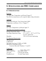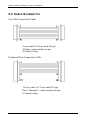
1
AT Series Transformer Testers Calibration System User Manual www.voltech.com www.voltech.com AT SERIES CALIBRATION SYSTEM USER MANUAL Thank you for choosing to use this Voltech product. If you experience any difficulty during installation or use of the AT Series Calibration System, or are unsure of any of its features or abilities, please do not hesitate to contact either your local supplier or a Voltech main service center as listed below. Voltech Instruments Inc. North Carolina, USA Voltech Instruments Ltd. Oxfordshire, UK Tel: +1 919 431 0015 Fax: +1 919 431 0090 Tel. +44 (0)1235 834555 Fax. +44 (0)1235 835016 [email protected] [email protected] Voltech AT Series Calibration System Manual Voltech Instruments are committed to a policy of continuous product development. Hence product specification and the information given in this manual are subject to change without notice. No part of this publication may be reproduced, stored in a retrieval system, or transmitted in any form, or by means electronic, mechanical photocopying, recording or otherwise without prior written permission of Voltech Instruments. All rights reserved. 1999-2002 Voltech Instruments Microsoft, Windows and the Windows logo are either registered trademarks or trademarks of Microsoft Corporation in the United States and/or other countries. Voltech Part Number 98-064, Issue 3. Voltech AT Series Calibration System Manual TABLE OF CONTENTS 1. INTRODUCTION 1.1 1.2 1.3 1.4 1.5 1.6 Features of the Calibration System General Safety Instructions Risk of Damage to Calibration Fixture Calibration – General Description Verification – General Description Pre-Calibration Verification – General Description 1.7 What Else Do You Need 1.8 The Calibration Environment 2. Quick Start How Calibration Works Performing Calibration Printing Calibration and Verification Certificates 3.5 Verification Only 3.6 Pre-Calibration Verification 3.7 Stored Calibration Data 3-1 3-2 3-4 3-19 3-20 3-21 3-26 CALIBRATING THE FIXTURE 4.1 Calibrating the Fixture 4.2 Fixture Calibration Method 4.3 Record of Measured Values 5. 2-1 2-2 2-4 CALIBRATION 3.1 3.2 3.3 3.4 4. 1-10 1-12 GETTING STARTED 2.1 Package Contents 2.2 Automatic or Manual Calibration 2.3 Installing the Calibration Program 3. PAGE 1-1 1-3 1-5 1-6 1-8 1-9 4-1 4-3 4-5 WARRANTY AND SERVICE 5.1 Warranty 5.2 Limitation of Warranty 5.3 Service 5-1 5-2 5-3 Voltech AT Series Calibration System Manual TABLE OF CONTENTS - CONTINUED 6. SPECIFICATION AND EMC COMPLIANCE 6.1 6.2 6.3 6.4 Specification Cable Schematics Declaration of CE Conformity EMC Precautions PAGE 6-1 6-2 6-3 6-4 7. VOLTMETER SPECIFICATION 7.1 Specification for Suitable Voltmeter 8. TROUBLESHOOTING 7-1 8-1 Voltech AT Series Calibration System User Manual 1. INTRODUCTION 1.1 FEATURES OF THE CALIBRATION SYSTEM The Voltech AT Series Calibration System consists of a calibration fixture, a PC (not supplied) running the Voltech calibration software, a printer and a precision digital voltmeter (not supplied). • For calibrating Voltech AT series testers such as the ATi and AT3600, but not the discontinued products AT1000 and AT3500. • All the precision components and circuits are contained within a single fixture that fits into the normal AT fixture position. • All interconnecting leads except those needed for the DVM are supplied. (Existing PC Editor cable required). • Semi-automatic or fully automatic calibration process. (For fully automatic calibration, an HP3458A DVM and a PC IEEE interface are required). • DOS software package with simple user interface controls the entire calibration and verification procedure. • Software prints a formal calibration certificate. PAGE 1-1 Voltech AT Series Calibration System User Manual • Calibration data may be saved to disk as a record of calibration constants and for recording drift between calibrations. • Stable, precision verification components are supplied and fitted internally. These components may be calibrated externally by a third party to demonstrate complete measurement traceability. PAGE 1-2 Voltech AT Series Calibration System User Manual 1.2 SAFETY INSTRUCTIONS CAUTION. RISK OF ELECTRIC SHOCK General Precautions: During some stages of the calibration procedure, high voltages are generated on the calibration fixture and on the outputs to the voltmeter. It is the responsibility of the user to ensure the compliance of the installation and use of this equipment with any local regulations that may be in force. Only qualified personnel should install this equipment and only after reading and understanding this user’s guide. These operating instructions should be adhered to. If in any doubt, consult your supplier. This equipment is for professional indoor use only. No liability is accepted for the inappropriate, negligent, or incorrect set-up of the instrument by the user, by either manual or automated means. PAGE 1-3 Voltech AT Series Calibration System User Manual CAUTION: 1. Before use, always connect the green earth terminal on the calibration fixture to the green earth terminal that is at the rear of the top plate of the tester. 2. Always use undamaged safety insulated test leads with a rating greater than 600 Volts for connection to the voltmeter. 3. Do not remove the cover from the calibration fixture. There are no user-serviceable parts inside. PAGE 1-4 Voltech AT Series Calibration System User Manual 1.3 RISK OF DAMAGE TO CALIBRATION FIXTURE VERY IMPORTANT Do not run any test programs with the calibration fixture fitted, the signals generated by the AT series testers during normal operation could permanently damage the calibration components inside the fixture. RUN X PAGE 1-5 Voltech AT Series Calibration System User Manual 1.4 CALIBRATION – GENERAL DESCRIPTION Calibration should be carried out periodically to ensure that the measurements made by an instrument remain within its published specification. Voltech recommends a calibration interval of one year. Calibration compensates for the small changes that may have taken place to electronic components and circuits over a period of time. The AT series testers make high-precision measurements using a network of amplifiers, current shunts and analogue to digital converters. For each range, on each shunt, and at various frequency points throughout the frequency range, the tester must store a calibration constant. Since the AT series testers are digital instruments, the result of a measurement of voltage or current is a binary number. The value of this number depends on the shunt used (in the case of current measurements), the settings of the amplifiers, and the output of the analogue to digital converter. To convert this binary number into a value for the voltage or current measured, the tester uses the stored calibration constants. Before a new tester is dispatched from Voltech Instruments, it is put through a calibration procedure that applies many voltages and currents throughout the frequency range of the tester. Each applied signal is measured by the tester and also by a very high precision PAGE 1-6 Voltech AT Series Calibration System User Manual voltmeter, which is itself regularly calibrated and traceable to international standards (NIST and NPL). The calibration constants within the tester are set for each applied signal, so that its measurements agree with this voltmeter. Currents are calibrated using the same voltmeter and a current shunt. The purpose of calibration is to set the calibration constants within the tester, so that its measurements are, as far as possible, in agreement with the international standard Volt and Amp. All the tests carried out by the AT series tester, capacitance, inductance, turns ratio, etc., derive their results through sophisticated algorithms from measurements of the two fundamental electrical quantities of the Volt and the Amp. PAGE 1-7 Voltech AT Series Calibration System User Manual 1.5 VERIFICATION – GENERAL DESCRIPTION By making a number of different measurements, at different operating points, on different sample components, the verification process checks that the calibration has been successful. Real measurements are made on a series of stable, precision components, and the values recorded are checked against appropriate limits. The calibration fixture includes a ‘standard’ capacitor and inductor that may be measured using separate traceable equipment to provide traceability for the verification. PAGE 1-8 Voltech AT Series Calibration System User Manual 1.6 PRE-CALIBRATION VERIFICATION – GENERAL DESCRIPTION By making a number of different measurements, at different operating points, on different sample components, the pre-calibration verification process verifies that the AT series tester is still within calibration. As part of the pre-calibration verification process, pass or fail verification reports may be printed. (For more information on how to print verification reports or certificates of conformance and calibration, refer to section 3.4 of this user manual.) PAGE 1-9 Voltech AT Series Calibration System User Manual 1.7 WHAT ELSE DO YOU NEED? In addition to the Voltech Calibration System you will need the following: • A PC with MS-DOS version 6, Windows 3.1x, 95, 98 or NT operating system installed. The minimum PC specification is 386 with 4MB of RAM and one spare serial port (COM1 or COM2). • A high-precision voltmeter. The Hewlett Packard HP3458A is recommended (and will be essential if you wish to calibrate fully automatically, see section 2.2). A specification for the required voltmeter is included in chapter 7. • The Editor RS232 cable supplied with your tester. • A Voltech approved safety system, if an AT3600 or AT1600 model is to be calibrated. An interlock bypass may be used, if the calibration is to be performed in an environment restricted to qualified, authorized personnel only. See the AT1600 / AT3600 user manual for the safety interlock specification. Consult your Voltech supplier if you are in any doubt as to the safety requirements. • A printer connected to the PC parallel port, LPT1. PAGE 1-10 Voltech AT Series Calibration System User Manual • For fully automatic calibration, an IEEE488.2 communications card must be fitted to your PC. See section 2.2 for the difference between fully automatic and manual calibration. PAGE 1-11 Voltech AT Series Calibration System User Manual 1.8 THE CALIBRATION ENVIRONMENT Calibration and verification should be carried out in a temperature and humidity-controlled environment where possible. The full specification of the tester is achieved, when calibration is carried out: • After a 1 hour warm-up of the AT • At a temperature of 23°C ± 5°C. • With 10 to 90% relative humidity, non-condensing. Calibration at other temperatures is acceptable, particularly if the tester is to be used regularly at that temperature, but you should check the validity of the calibration of the DVM that is to be used at that calibration temperature. If calibration is to be performed outside a temperature-controlled environment, care should be taken to avoid rapid changes in temperature after warm-up and during the calibration process. PAGE 1-12 Voltech AT Series Calibration System User Manual 2. GETTING STARTED 2.1 PACKAGE CONTENTS Your AT Series Calibration System should arrive complete with the following components: 1. A calibration fixture with sockets for connecting to a DVM (digital voltmeter) and an AT Series Tester. (VPN 100-060) 2. Voltech AT Series Calibration System Software on a 3½” floppy disk. (VPN 88-189) 3. Earth lead for connecting to the Earth terminal on top of the AT Series Tester. (VPN 77-021) 4. 9-way to 9-way connection cable with D-type plugs for connecting to the user port of the tester. (VPN 77-020) 5. 15-way to 15-way connection cable with D-type plugs for connecting to the peripheral port of the tester. (VPN 77-019) 6. A certificate of calibration and conformance. 7. A warranty registration card. 8. A storage box and this user manual. Please complete the warranty registration card and return it to Voltech in the UK or USA. Registering your calibration system is important because it means that we can keep you up to date with the latest software and features of the calibration system. If any of the above items are missing, please contact your local supplier. PAGE 2-1 Voltech AT Series Calibration System User Manual 2.2 AUTOMATIC OR MANUAL CALIBRATION Manual Calibration A PC + DVM, as specified in Appendix B, are all that is required to complete the calibration system. Calibration takes approximately 120 minutes, during which you will be asked to enter 30 or more readings from the DVM into the computer. Automatic Calibration A PC + the HP3458A DVM + an IEEE488 controller fitted to the PC are required for fully automatic calibration. Calibration will take about 90 minutes; readings from the DVM being taken automatically via the IEEE interface. Fully automatic calibration is the process used by Voltech and its authorized service centers. PAGE 2-2 Voltech AT Series Calibration System User Manual IMPORTANT For fully automatic calibration, an IEEE488 interface must be fitted to the PC with the latest MS-DOS software drivers for the interface installed and working. If in doubt, check with the supplier of your IEEE488 interface that you have the latest MS-DOS software driver available. This will probably be different to any Windows driver you may be using. Most driver packages include some diagnostic software, and you should run this to confirm that the interface is working before attempting to use the calibration program. The following 'ISA' bus interfaces have been tested with the Voltech calibration software, but most interfaces should be compatible. Beware that new PCs do not have an 'ISA' bus. Consult your IEEE488 interface supplier for advice. National Instruments PCII/IIA with driver version 2.6 or greater. Iotech GP488 with driver ‘Driver488/SUB’ version 4 or greater. (The driver must be the enhanced ‘/SUB’ version) CEC most cards can be used without a driver. PAGE 2-3 Voltech AT Series Calibration System User Manual 2.3 INSTALLING THE CALIBRATION PROGRAM The program uses the MS-DOS operating system, a version of which is supplied with all current versions of the Windows operating system. A PC that has the MS-DOS operating system only can be used, but most users will find it more convenient to use Windows. A Windows installation will take approximately 5 minutes, and you will be required to create a Windows program item or shortcut to complete the process. Complete instructions are given below, but if you are unfamiliar with creating program items or shortcuts, then you may need to consult your system administrator or the Windows help system during installation. 2.3.1 MS-DOS INSTALLATION 1. The PC must be switched on and the command prompt ‘c:\>’ or similar displayed. 2. Insert the set-up disk in drive A:. 3. Type ‘a:\install.exe’ and press the return key. 4. The software will prompt for the letter of the drive on which the files will be installed. This is normally the ‘C:\’ drive. PAGE 2-4 Voltech AT Series Calibration System User Manual Type ‘c’. 5. The software will offer the default directory of ‘c:\ATCAL’. To accept this, press the return or ‘Enter’ key. 6. For a first-time installation, the software will ask you to confirm if it is OK to create a new directory. Type ‘y’. 7. The software will now install from the floppy disk drive to the hard disk drive of the PC. When finished, press any key, and the installation window will close. To run the program under MS-DOS, simply type ’c:\atcal\atcal.exe’ for fully automatic calibration using IEEE488 communications to the DVM or ’c:\atcal\atcal.exe –m’ for manual calibration. For a 1MHz calibration, add ‘-1’ to the command line, i.e., c:\atcal\atcal.exe –1 or combine the command line switches PAGE 2-5 Voltech AT Series Calibration System User Manual for a manual, 1 MHz calibration, i.e., c:\atcal\atcal.exe –1 – m. 2.3.2 WINDOWS 3.1X INSTALLATION 1. Insert the set-up disk in drive A:. 2. Close all applications. 3. In the program manager, select ‘File’. 4. From the pop-up menu select ‘Run…’. 5. Type ‘a:\install.exe’ into the dialogue box and click on OK. 6. The software will prompt for the letter of the drive on which the files will be installed. This is normally the ‘C:\’ drive. PAGE 2-6 Voltech AT Series Calibration System User Manual Type ‘c’. 7. The software will offer the default directory of ‘c:\ATCAL’. To accept this, press the return or ‘Enter’ key. 8. For a first-time installation, the software will ask you to confirm if it is OK to create a new directory. Type ‘y’. 9. The software will now install from the floppy disk drive to the hard disk drive of the PC. When finished, press any key and the installation window will close. 10. Next, create a Windows program item for the program ‘atcal.exe’ which will be in the ‘c:\ATCAL\’ directory, unless you changed it, as above. First of all, click on (or create if you wish) the program group where the item will be placed. For example, just click on the program group called ‘Applications’. PAGE 2-7 Voltech AT Series Calibration System User Manual In the program manager, select ‘File’, then ‘New…’. Click on ‘Program Item’ and ‘OK,’ and you will see the following dialogue: 11. Fill in the boxes as above. IMPORTANT The ‘Command Line:’ must read: c:\atcal\atcal.exe for fully automatic calibration using IEEE488 communications. You must add ’–m’ to this line for manual calibration, i.e., c:\atcal\atcal.exe –m. For a 1MHz calibration, add ‘-1’ to the command line, i.e., c:\atcal\atcal.exe –1. You may also combine these command line switches, e.g., enter c:\atcal\atcal.exe –1 –m for a manual, 1 MHz calibration. Note there is a space before the '-'. PAGE 2-8 Voltech AT Series Calibration System User Manual 12. Click OK to save changes. These settings can be changed at any time. The calibration program can now be run by double-clicking on the program item. 2.3.3 WINDOWS 95, 98 OR NT INSTALLATION 1. Insert the set-up disk in drive A:. 2. Shut down all applications. 3. Select ‘Start’ from the task bar. 4. Select ‘Run’ from the pop-up menu. 5. Type: ‘a:\install.exe’ into the dialogue box. Click on ‘OK’. PAGE 2-9 Voltech AT Series Calibration System User Manual 6. The software will prompt for the letter of the drive on which the files will be installed. This is normally the ‘C:\’ drive. Type ‘c’. 7. The software will offer the default directory of ‘c:\ATCAL’. To accept this, press the return or ‘Enter’ key. 8. For a first-time installation, the software will ask you to confirm if it is OK to create a new directory. Type ‘y’. 9. The software will now install from the floppy disk drive to the hard disk drive of the PC. When finished, press any key, and the installation window will close. PAGE 2-10 Voltech AT Series Calibration System User Manual 10. Next, create a Windows ‘shortcut’ to the program ‘atcal.exe,’ which will be in the ‘c:\ATCAL.exe’ directory, unless you changed it, as above. Locate the file using the Windows explorer, mouse right-click on it and select ‘Create Shortcut’. 11. Now right click on the ‘Shortcut to Atcal.exe’ and select ‘Properties’. Click on the ‘Program’ tab and examine the command line. IMPORTANT The ‘Command Line:’ must read: c:\atcal\atcal.exe for fully automatic calibration using IEEE488 communications. You must add ’–m’ to this line for manual calibration, i.e., c:\atcal\atcal.exe –m. For a 1MHz calibration, add ‘-1’ to the PAGE 2-11 Voltech AT Series Calibration System User Manual command line, i.e., c:\atcal\atcal.exe –1. You may also combine these command line switches, e.g., enter c:\atcal\atcal.exe –1 –m for a manual, 1 MHz calibration. 12. It is also recommended, but not essential, that you now click on the ‘Screen’ tab and select ‘Usage’ as ‘Full-screen’. With this selected, the calibration program will completely fill the PC screen, when it is run, rather than appearing in a window. Many potential display problems can be avoided this way. PAGE 2-12 Voltech AT Series Calibration System User Manual 13. Click OK to save changes. These settings can be changed at any time. The calibration program can now be run by doubleclicking on ‘Shortcut to Atcal.exe’. The shortcut can be copied or moved to the Windows desktop or Start Menu as you wish. (Consult the Windows help system, if you are unsure). The software is now installed and ready for use. PAGE 2-13 Voltech AT Series Calibration System User Manual PAGE 2-14 Voltech AT Series Calibration System User Manual 3. CALIBRATION 3.1 QUICK START A brief overview of the process. If you have used the calibration system before, these instructions may be all that you need. 1. Check the AT to be calibrated has firmware version 2.45 or greater fitted. (This is shown on the display of the tester during switchon). 2. Warm up the tester for at least 1 hour by simply switching it on. 3. Connect a safety interlock system (AT1600 and AT3600 only). 4. Connect the PC to the tester (and DVM for fully automatic calibration). DO NOT FIT THE CALIBRATION SYSTEM TO THE TESTER. 5. Run the Voltech calibration PC software. 6. Press ‘4’ to check the configuration of the system. 7. Press ‘1’ to start calibration and verification. Follow the on-screen instructions. You will be prompted to fit the fixture to the tester during this process. 8. Press ‘3’ to print certificates. 9. Press ‘5’ to close the program. PAGE 3-1 Voltech AT Series Calibration System User Manual 3.2 HOW CALIBRATION WORKS Before starting calibration, the program runs the tester’s self test to ensure that the tester is working correctly and can be calibrated. The funcionality of the user port is also checked. Next, a set of precision resistors inside the fixture are measured very precisely using the DVM. These resistors are used as described later. During calibration the AT Series Tester uses its own internal generators to produce specific voltage and frequency combinations, which are known as calibration points. For each calibration point on a particular measuring range of the tester, the tester’s measurement is compared with that of the DVM. Provided that the DVM reading is within a few percent of the tester’s reading, a calibration factor is calculated for each point. The rest of the tester’s ranges are then calibrated by cross-reference to the first range. The current ranges are calibrated first using the pre-calibrated resistors. After this calibration, current can be measured very accurately by the tester, especially at the calibration points. If the PAGE 3-2 Voltech AT Series Calibration System User Manual same, very accurately measured calibration point currents are then generated by different voltages across different (but pre-calibrated resistors), then the voltage ranges can be calibrated using Ohm’s law. The accuracy of any Voltech tester at its chosen calibration points is significantly better than its published specification. This allows us to use this method and accurately calibrate the entire measurement range of the tester at high speed and with only a few measurements required from the external DVM. A calibration factor is calculated for each calibration point, on every range of the tester’s measuring circuits. The calibration factors are used by the tester during normal operation to produce calibrated measurements. PAGE 3-3 Voltech AT Series Calibration System User Manual 3.3 PERFORMING CALIBRATION 3.3.1 WARMING UP AND PRELIMINARY CONNECTIONS 1. Switch on the tester to be calibrated and check the firmware version number that is shown on the display during switchon. If that number is less than 2.45, contact your supplier for a free-of-charge upgrade. 2. Leave the tester and DVM switched on for at least 1 hour before starting calibration. 3. For the AT1600 and AT3600 only, connect a safety system to the safety interlock of the tester. High voltages will be present during calibration. 4. Switch on the PC and confirm the Voltech calibration software has been installed correctly. 5. For fully automatic calibration only, check that the DVM is an HP3458A and that the PC has an IEE488 interface fitted, installed and working. Connect the IEEE488 interfaces of the PC and HP3458A together. 6. Connect the serial port of your PC to the tester’s auxiliary port using the cable you use to program the tester from the Voltech AT Series Editor. 7. Connect your printer to your PC. If your PC is networked, and you usually use a network printer, this will not be necessary. PAGE 3-4 Voltech AT Series Calibration System User Manual PAGE 3-5 Voltech AT Series Calibration System User Manual 3.3.2 STARTING THE PC SOFTWARE 1. Run the program as described in the software installation chapter, 2.3. The time and date is taken from the PC clock and will usually be correct. Press ‘1’ to set the time, ‘2’ to set the date, if required. Then press ‘3’ to continue. PAGE 3-6 Voltech AT Series Calibration System User Manual 2. Press ‘4’ to configure the system. PAGE 3-7 Voltech AT Series Calibration System User Manual Press ‘1’ to choose between the available COM ports on your PC. This is the COM port that will be connected to the Editor port on the AT. Press ‘2’ to change the company name. This is the name of the company performing the calibration, and it will be shown on the printed certificates. Press ‘3’ to return to the main menu once these details are correct. PAGE 3-8 Voltech AT Series Calibration System User Manual 3.3.3 STARTING CALIBRATION AND VERIFICATION 1. From the main menu of the software, press ‘1’ to begin the calibration process. You will be asked to confirm that the serial cable between the tester and PC is connected (press ‘Enter’) and then you will see the following screen: Menu Options Command prompt Progress Information The top half of the screen is a menu of possible program options, and the bottom half of the screen will contain information on the current status or progress of the current operation. The most important area is the lighter coloured bar across the middle, where you will be prompted for input. PAGE 3-9 Voltech AT Series Calibration System User Manual As prompted: ‘Remove any fixture and press a key to continue’, and the tester will begin a self test to confirm that all its generators, measuring circuits and relays are working properly. This ensures that calibration will be carried out on a fully functioning tester that is fitted with firmware version 2.45 or greater. 2. You will now see a series of screens prompting you to enter information concerning the calibration fixture and the DVM. It is important to enter this information correctly because it is used to identify the traceability of the calibration on the final certificate. PAGE 3-10 Voltech AT Series Calibration System User Manual Enter the serial number of the calibration fixture. It will be similar to: TY99/1234. Press 'Enter' and then 'Y' to confirm. Next, you will be asked to enter the value of the calibration fixture capacitor value: Enter the value of the standard capacitor, as shown on the label on the underside of the calibration fixture in picofarads (pF). E.g., ’98.83’. Press 'Enter' and then 'Y' to confirm. PAGE 3-11 Voltech AT Series Calibration System User Manual Then enter the inductor value in milli-Henries. E.g., ‘1.001’. Press 3. 'Enter' and then 'Y' to confirm. The software prompt will now ask you to fit the calibration fixture to the top of the tester. Do not forget to connect the green earth socket on the tester to the green socket on the fixture using the green lead provided. PAGE 3-12 Voltech AT Series Calibration System User Manual Don’t forget to connect the earth lead (AT1600 and AT3600 shown) Press any key and then connect the DVM to the calibration fixture using safety leads that are in good condition and with insulation rated for more than 600 volts. The cables should be less than 1 meter (three feet) long, and each pair should be twisted together to minimize external inteference. You will need to make a four-wire connection to the fixture, the V hi and lo on the fixture to V hi and lo on the meter AND ohms sense hi and lo on the fixture to ohms hi and lo on the meter. PAGE 3-13 Voltech AT Series Calibration System User Manual 4-wire DVM connection, user port and earth (AT1600 and AT3600 shown) PAGE 3-14 Voltech AT Series Calibration System User Manual Press any key and then enter the serial number of the DVM. For a manual calibration only, you will also be prompted for the DVM model number. (During a fully automatic calibration, the DVM is checked to confirm it is an HP3458A). Press 'Enter' and then 'Y' to confirm. Then (as prompted) fit the 9-way to 9-way D-type lead provided between the user port of the tester and the user port of the calibration fixture. It is not necessary to follow this exact sequence of connections. Once the tester has performed a self-test, the earth, DVM and user port connections can all be made in any order. The software prompts are simply reminders. PAGE 3-15 Voltech AT Series Calibration System User Manual Calibration will now begin. Fully Automatic Calibration No further action is required. The process will take about 90 minutes, during which you will see a large number of measurements being made and calibration constants calculated and stored. At the end of calibration, the process of verification will begin, and you will be asked to confirm the connections as above. Manual Calibration The process is semi-automatic. When prompted by the software, you will be asked to select Ohms Four-wire, AC Volts and DC Volts on the DVM and enter more than 40 readings. IMPORTANT Make sure that the DVM is set up correctly when prompted AND in the best way to achieve optimum accuracy. For example, you may have to increase the averaging depth of the display to improve readability and accuracy. PAGE 3-16 Voltech AT Series Calibration System User Manual It is VERY IMPORTANT to set Ohms FOUR-WIRE mode, whenever the software prompts for ohm measurement. DVM readings must be entered into the software to 5 significant figures, and with the decimal point in the normal position. For example, if the meter displays 0.1234567kΩ, then enter 123.46 into the software. At the end of calibration, the process of verification will begin, and you will be asked to confirm the connections as above. Further readings will be required from the DVM. Note that the new calibration factors are NOT stored within the tester until verification has been completed successfully. This is to ensure that the tester is never rendered inoperable if something should go wrong during the calibration process. Please refer to the ‘TROUBLESHOOTING’ chapter of this manual, if you see any unusual error messages or warnings during calibration. PAGE 3-17 Voltech AT Series Calibration System User Manual 3.3.4 SUMMARY OF ENTERED DATA 1. Time and date (Check) 2. COM port and company name (Check) 3. Calibration fixture serial number* 4. Capacitor value* 5. Inductor value* 6. DVM serial number* 7. DVM model (manual calibration only)* * Data that must be entered every time a calibration is performed. PAGE 3-18 Voltech AT Series Calibration System User Manual 3.4 PRINTING CALIBRATION AND VERIFICATION CERTIFICATES After a succesful verification, certificates of conformance and calibration can be printed, together with verification results. Simply choose ‘3’ from the PC software opening menu. The conformance certificate should be signed by an authorized person, according to your company’s quality procedures. PAGE 3-19 Voltech AT Series Calibration System User Manual 3.5 VERIFICATION ONLY Verification is used to confirm a successful calibration by verifying that the tester accurately makes measurements on the pre-calibrated resistors, inductor and capacitor. High voltages (as used for the magnetizing current and hi-pot tests of the AT3600) are also checked. Verification can be performed at any time after calibration to confirm the validity of the last calibration, but normally it is just used as part of the calibration process. PAGE 3-20 Voltech AT Series Calibration System User Manual 3.6 PRE-CALIBRATION VERIFICATION Pre-calibration verification is used to confirm that the tester conforms to its published specification and accurately makes measurements on the pre-calibrated resistors, inductor and capacitor. High voltages (as used for the magnetizing current and hi-pot tests of the AT3600) are also checked during this process. Pre-calibration verification can be performed at any time prior to calibration to confirm the validity of the most recent calibration. As part of the pre-calibration verification process, pass or fail verification reports may be printed. PAGE 3-21 Voltech AT Series Calibration System User Manual 3.6.1 STARTING PRE-CALIBRATION VERIFICATION 1. Start the calibration software and, from the main menu, choose ‘2. Verification and Extra Tests’. PAGE 3-22 Voltech AT Series Calibration System User Manual 2. Next, enter ‘1’ for ‘Full Verification Only’ to begin the precalibration verification process. 3. Then, you will go through a series of screens prompting you to enter and verify information concerning the calibration fixture and the DVM. It is important to enter this information correctly because it is what will be used on the final pre-calibration verification report. (See section 3.3.3 for more detail on how to correctly enter this information.) 4. When you have finished entering the data for the calibration fixture, you will be prompted to connect the DVM to the IEEE bus of the PC and to the calibration fixture. At this time, you may also fit the calibration fixture to the top of the AT series PAGE 3-23 Voltech AT Series Calibration System User Manual tester and connect the fixture to the tester. (See section 3.3.3 for more information on how to make these connections.) Then, hit ‘Enter’. 5. Finally, you will be prompted to enter the serial number of the DVM and to connect the AT series tester to the PC via a serial link. Hit ‘Enter’, and pre-calibration verification will begin. PAGE 3-24 Voltech AT Series Calibration System User Manual 3.6.2 PRINTING PRE-CALIBRATION VERIFICATION REPORTS Once the pre-calibration verification process is complete, return to the main menu and choose ‘3. Print Certificate’ to print a formal pass or fail pre-calibration verification report. PAGE 3-25 Voltech AT Series Calibration System User Manual 3.7 STORED CALIBRATION DATA The AT calibration software produces data files that are in CSV (comma-separated, variable) format for importing into common spreadsheet and database programs. These files are stored in directories that are placed in the installation directory. The directory name is the serial number of the instrument that has been calibrated or verified. Two files are produced - one called ‘calib.csv’ after a calibration has been performed and another called ‘verify.csv’ after verification. New results are appended to these files after each calibration or verification takes place to build up a picture over time. These stored results can be used to track the instrument’s drift over time and change the calibration interval if desired. PAGE 3-26 Voltech AT Series Calibration System User Manual 4. CALIBRATING THE FIXTURE 4.1 CALIBRATING THE FIXTURE None of the components that are used during the calibration procedure require calibration as the system uses the precision voltmeter to accurately measure the values of these components at the time of calibration. However, there are two components on the fixture that are only used during verification. These are a capacitor and an inductor. Before a new calibration system is shipped from Voltech Instruments, these two components are accurately measured with NPL/NIST traceable instruments, and the measured values are written in the table on the underside of the fixture. These components should be measured accurately every year. It is not necessary to have these components calibrated by an accredited calibration laboratory. However, the equipment used must have a traceable calibration and an accuracy typically better than 1.0% at the test conditions below. The traceable uncertaintity of these measurements is transferred to the uncerataintity of the verification only. The overall calibration of the ATs to be calibrated is not effected by these verification measurements. PAGE 4-1 Voltech AT Series Calibration System User Manual Component Nominal Value Test Voltage Test Frequency Capacitor 100pF 5V 10kHz Inductor 1mH 100mV 3kHz Further, the meter must be capable of Kelvin (four-wire) measurements and have facilities for open-circuit and short-circuit compensation. If you do not have the equipment required to do this, it is normally possible to hire it. Alternatively, you may contact your local Voltech supplier to arrange to have the fixture calibrated. PAGE 4-2 Voltech AT Calibration System User Mnual 4.2 FIXTURE CALIBRATION METHOD The connections to the internal capacitor and inductor are shown on the underside of the fixture. IMPORTANT 1. Perform a short-circuit compensation of the LC meter and the fourterminal leads and clips you will be using. 2. Perform an open-circuit compensation WITH THE METER CONNECTED, ACROSS PINS 16 and 18. This will ensure that the tester will be able to make the same compensation measurements as the LC meter. PAGE 4-3 Voltech AT Series Calibration System User Manual You can now measure the components using the test conditions above. The inductor is between pins 18 and 20; the capacitor between pins 14 and 16. In order to avoid losing the measured value of these components, we suggest that you fill in the values in the table overleaf as well as on the underside of the fixture. PAGE 4-4 Voltech AT Calibration System User Mnual 4.3 RECORD OF MEASURED VALUES Serial Number L and C Used for Calibration Verification C pF L mH Date of Measurement PAGE 4-5 Voltech AT Series Calibration System User Manual PAGE 4-6 Voltech AT Series Calibration System Manual 5. WARRANTY AND SERVICE 5.1 WARRANTY The AT Series Calibration System (System) is warranted against defects in materials and workmanship for a period of twelve (12) months from the date of shipment. In the event of failure of a System due to faulty materials or workmanship during this period: 1. Voltech will, at their discretion, either repair or replace the faulty system free-of-charge. Shipment of the faulty System to the nearest authorized Voltech service center shall be the responsibility of the customer. 2. Voltech shall pay the return shipment charges from the Voltech authorized service center to the customer. 3. Measure the verification components on the System before dispatch and provide the measured values to the customer. PAGE 5-1 Voltech AT Series Calibration System User Manual 5.2 LIMITATION OF WARRANTY This warranty shall not apply to defects resulting from unauthorized modification or misuse of the System. Voltech shall be the sole arbiter in these cases. No other warranty is expressed or implied. While every care has been taken in compiling the information in this manual, Voltech Instruments cannot accept legal liability for any inaccuracies contained herein. Voltech Instruments has an intensive program of design and development, which may alter product specification. Voltech reserves the right to alter specification without notice and whenever necessary to ensure optimum performance from its product range. Because software is inherently complex and may not be completely free from errors, in no event, will Voltech be liable for direct, indirect, special, incidental or consequential damages arising out of the use of or inability to use software or documentation, even if advised of the possibility of such damage. In particular, Voltech is not responsible for any lost profits or revenue, loss of use of software, loss of data, cost of substitute software, claims by third parties, or for other similar costs. In no case shall Voltech's liability exceed the amount of the license fee. PAGE 5-2 Voltech AT Series Calibration System User Manual 5.3 SERVICE Should this product become faulty outside the warranty period, contact your local Voltech supplier who will be able to advise you on the cost of repair and where to send the faulty System. DANGER OF ELECTRIC SHOCK Do not attempt to repair the System. The Voltech AT Series Testers can produce lethal voltages during calibration. Incorrect repairs to the System could result in these voltages being accesible to the operator or damage to the tester. PAGE 5-3 Voltech AT Series Calibration System User Manual PAGE 5-4 Voltech AT Series Calibration System User Manual 6. SPECIFICATION AND EMC COMPLIANCE 6.1 SPECIFICATION Resistors 1% metal film. Temperature coefficient 50 ppm/oC True Kelvin connections on all except the high-voltage attenuator Capacitor Polystyrene dielectric. Tan δ better than 0.0005 Temperature coefficient -50 to -170ppm/ oC Inductor Air-cored. Temperature coefficient 2ppm/ oC Operating Environmental Conditions Storage temperature range Operating temperature range Humidity -40 oC to 70 oC. 0 oC to 40 oC. (18 oC to 28 oC for accurate calibration) 10% to 90% non-condensing PC Minimum Requirements 386 processor 4 MB RAM One spare serial port (COM1 or COM2) MS-DOS 6 Operating system Tested on Microsoft Windows 3.1 and 95 Connectors: Earth terminal DVM connection User port Peripheral port 4mm safety socket 4mm safety socket 9-way D-type female 15-way D type female PAGE 6-1 Voltech AT Series Calibration System User Manual 6.2 CABLE SCHEMATICS User Port Connection Cable 9-way male to 9-way male D-type All pins connected pin to pin 0.5 metres long Peripheral Port Connection Cable 15-way male to 15-way male D-type Pins 1 through 9, connected pin-to-pin 0.5 meters long PAGE 6-2 Voltech AT Series Calibration System User Manual 6.3 DECLARATION OF CE CONFORMITY DECLARATION OF CONFORMITY Manufacturer's Name Voltech Instruments Ltd Manufacturer's Address 65 Milton Park Abingdon, Oxon United Kingdom declares, that the product Product Name: AT Series Calibration Fixture Model Number: ATCAL conforms to the following Product Specifications when used as directed with an AT series transformer tester: Safety: BS EN 61010 (1993) EMC: BS EN 55022 (1995): Class A BS EN 50082-2 (1992) Supplementary Information: The product herewith complies with the requirements of the EMC Directives 89/336/EEC and 92/31/EEC and the Low Voltage Directive 73/23/EEC Signed for on behalf of Voltech Instruments Ltd Tim Keep, Engineering Manager Abingdon, United Kingdom, March 30, 1999 PAGE 6-3 Voltech AT Series Calibration System User Manual 6.4 EMC PRECAUTIONS Conducted and Radiated Emissions The AT Calibration Fixture complies with the limits of BS EN 55022, Class A, when used as directed with an AT series transformer tester. Immunity The AT series tester used with the calibrator may be susceptible to fast electrical transient on the power line and to electrical discharges, which can disrupt the operation of the unit. Should such an event occur, the AT series tester and calibration fixture can be returned to normal operation by: 1. Switching off the tester. 2. Waiting 5 seconds. 3. Switching the tester back on again. PAGE 6-4 Voltech AT Series Calibration System User Manual 7. VOLTMETER SPECIFICATION 7.1 SPECIFICATION FOR SUITABLE VOLTMETER To calibrate an AT series tester with the Voltech Calibration System, a precision digital voltmeter (DVM) is required. Fully automatic calibration can only be performed with an HP3458A, but several other meters will be suitable for semi-automatic calibration. as long as they conform to this specification. The DVM must be capable of performing four-terminal DC resistance measurements, as well as ac and dc voltage measurements. The input impedance of the voltage measurement channel in the DVM must be at least 2MOhm at all times. Table of Measurement Points and Required Accuracy The table overleaf shows the voltage or resistance being measured, and the frequency at which the measurement is made. For each measurement, it shows the required accuracy. Use this table to decide whether a particular DVM will be suitable for calibrating your AT series tester. PAGE 7-1 Voltech AT Series Calibration System User Manual Please note that the accuracy shown is the worst-case accuracy, taking into account all sources of error within the DVM. When considering a DVM, be sure to use its full accuracy specification. DC Resistance Measured Value 500mΩ 75Ω 235Ω 750Ω 7.5KΩ DC Voltage Measured Value 200mV 600mV 2V 4V 600V AC Voltage Measured Value 404mV 404mV 404mV 404mV 404mV 404mV 404mV 404mV 404mV 5V 17V 50V 170V 250V PAGE 7-2 Frequency DC DC DC DC DC Maximum Error 0.05% 0.01% 0.01% 0.01% 0.01% Frequency Maximum Error DC DC DC DC DC 0.005% 0.005% 0.003% 0.003% 0.005% Frequency Maximum Error 100Hz 1KHz 10KHz 16.4KHz 100KHz 262KHz 500KHz 1MHz 3MHz 256Hz 256Hz 256Hz 256Hz 256Hz 0.04% 0.05% 0.05% 0.05% 0.70% 0.70% 2.00% 3.00% 5.00% 0.04% 0.08% 0.06% 0.10% 0.10% Voltech AT Series Calibration System User Manual 8. TROUBLESHOOTING If you have any problems installing or using the calibration system, your Voltech supplier will be pleased to help you, and you should not hesitate to call. It will help Voltech to get you the best possible remedy to any fault, if you have as much information available as possible. This includes the serial numbers of the AT and calibration fixture, the firmware version of the AT, and the calibration software revision. The list of possible faults and remedies below is not exhaustive, but may help you to overcome some common problems. 1. ‘Failure to Communicate with the DVM’ is shown at the beginning of calibration. There is a problem with IEEE488 communications to the DVM. If you are intending to calibrate manually you must use the command line ‘c:\atcal\atcal.exe –m’. See section 2.2. Note that there is a space between atcal.exe and ‘ –m’. If you are intending to calibrate automatically, please check that your IEEE488 interface is fitted and working properly, the DVM is switched PAGE 8-1 Voltech AT Series Calibration System User Manual on and the DVM and PC IEEE488 interfaces are connected together. Check that you are using the latest MS-DOS drivers (you may need to call the interface manufacturer). As a minimum, you should be able to run the PC IEEE488 interface’s diagnostic software and get some response from the DVM. 2. The AT Series Tester fails ‘Self Test’ at the beginning of calibration. Check that there is no fixture fitted, and that the tester has been warmed up properly. If the tester still fails ‘self test’ when repeated, call your supplier for advice. 3. Calibration or Verification Failure If the software detects a calibration constant that is outside prespecified limits, a calibration error will be reported. Retry if that option is available. If the problem persists, it may be due to: • Lack of warm-up. • Noise on DVM leads. • Calibration fixture not seated properly into the tester. PAGE 8-2 Voltech AT Series Calibration System User Manual • DVM not set up properly. (Manual calibration - Four-Wire resistance is very important.) • Fixture verification components (L & C) need calibration. • A problem with the tester. 4. Certificates do not print. Check that a printer is connected to LPT1 of your PC. If you are trying to use a network printer, the port LPT1 must be ‘captured’. Consult your network administrator or see the Windows help system under ‘Printers, Network, Ports’ for how to ‘capture’ a printer port. 5. Errors during ‘High Voltage’ calibration. Check that a safety interlock system has been fitted, and that it has not been interrupted during calibration and verification. This applies to the AT1600 and AT3600 only. See your tester’s user manual for complete information. 6. ‘Error: voltage measurement by DVM outside limits’. The DVM measurement is far away from the expected value. Automatic calibration or verification: PAGE 8-3 Voltech AT Series Calibration System User Manual • Check the DVM is connected properly (sense to sense, hi to hi, etc.). • Check the calibration fixture is located properly into the AT and tightened down. • Retry the measurement. Manual calibration or verification: • Check the DVM is connected properly (sense to sense, hi to hi, etc.). • Check the calibration fixture is located properly into the AT and tightened down. • Choose an appropriate manual range for the DVM measurement. • Retry the measurement. 7. (Manual Calibration or Verification) – DVM reading steadily drifts downwards. The AT has tripped because the DVM was on too low a voltage range. Choose an appropriate manual range on the DVM, enter ‘0’ as the value and then retry the measurement. PAGE 8-4 Voltech AT Series Calibration System User Manual 8. Calibration or verification certificate states 1MHz rather than 3MHz. The ' -1' switch has been used on the command line to force this so that calibration can be performed with a 1MHz meter. See the installation section of this manual. Also, some testers manufactured before 1999 cannot be calibrated to 3MHz. Contact your supplier with the firmware revision level and serial number of your tester for advice if you suspect this is the case. PAGE 8-5 Voltech AT Series Calibration System User Manual PAGE 8-6 Voltech Instruments Inc. North Carolina, USA Voltech Instruments Ltd. Oxfordshire, UK Tel: +1 919 431 0015 Fax: +1 919 431 0090 Tel: +44 (0)1235 834555 Fax: +44 (0)1235 835016 [email protected] [email protected] www.voltech.com