1
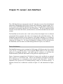
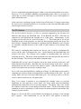
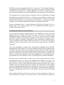
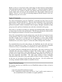
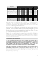
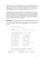
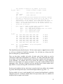
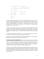
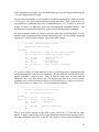
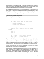
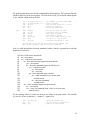
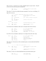
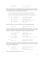
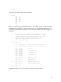
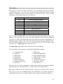
Additional Chapter for
Programming Microcontrollers
using
Assembly Language
by
Chuck Baird
This chapter tells how to use the AVR Butterfly’s DataFlash serial
memory chip, and develops a general purpose support routine.
Copyright 2006 © by Chuck Baird
All rights reserved
http://www.cbaird.net
i
ii
Chapter 15: Jumpin’ Jack DataFlash
The AVR Butterfly has an integrated circuit (IC) chip that is not used by the distributed
application, although that software does contain some rudimentary support routines for it.
It is the Atmel AT45DB041B DataFlash memory chip, a 4 megabit (half a million bytes)
nonvolatile serial memory interfaced via the SPI interface. The device datasheet which
includes all the details that follow (and much more) can be downloaded from the Atmel
website.
The DataFlash can be used to store a wide variety of data, from digital voice to collected
experimental data to program code ready to be written into the main flash memory. The
DataFlash cannot be directly read or written by AVR Studio, although it is accessible to
any SPI compatible device since the SPI pins on the Butterfly are brought out to the J400
connector (see Chapter 11). Of course, the Butterfly’s ATmega 169 can read and write
the DataFlash, and even make it available through the RS-232 port, as we shall see.
Device Architecture
The DataFlash memory array is arranged as 2,048 pages of 264 bytes each, for a total of
4,325,376 bits. In addition, there are two internal SRAM buffers of 264 bytes which
allows for overlapping operations: One buffer may be written to or read from the
DataFlash memory while the other buffer is being filled or emptied by the user.
Pages of memory are grouped into 256 blocks of 8 pages each, and blocks are grouped
into 6 sectors of 1 to 64 blocks each. Most of our operations will happen at the page
level, although there is a command to erase memory at the block level. Sectors are
important in one special case of refreshing memory which we will discuss shortly. A
diagram of the device’s architecture is shown in Figure 15.1 and summarized in Figure
15.2.
Figure 15.1 – DataFlash Memory Array Architecture
Sector
0
1
2
3
4
5
Block(s)
Pages
Bytes
0
0–7
2,112
1 – 31
8 – 255
65,472
32 – 63
256 – 511
67,584
64 – 127
512 – 1023
135,168
128 – 191
1024 – 1535
135,168
192 – 255
1536 – 2047
135,168
Each page is 264 bytes long
Each block is 8 pages long (2,112 bytes)
Figure 15.2 – Allocation of the DataFlash Memory
DataFlash Commands
There are 21 different operations we can perform with the DataFlash. For now we will
gloss over the details and look at the big picture, using the command names from the
Atmel datasheet. The pound sign (#) designates a buffer number, 1 or 2.
A) Continuous Array Read – a sequential stream of data is read from a specified
starting address in the main memory. Once the address is set up, any number of
bytes may be read without further addressing. If we reach the end of memory
(page 2047, byte 263), the address wraps back to the beginning (page 0, byte 0).
B) Main Memory Page Read – a sequential stream of data is read from a specified
starting address within a specified page of main memory. Once the address is
set up, any number of bytes may be read without further addressing. At the end
2
of the page (byte 263) the address wraps back to the beginning of the same page
(byte 0).
C) Buffer # Read – a sequential stream of data is read from a specified starting
address within one of the SRAM buffers. Once the address is set up, any
number of bytes may be read without further addressing. At the end of the
buffer the address wraps back to the beginning of the buffer.
D) Status Register Read – the device status register contents are returned. The
status register contains a device busy bit, a comparison results bit, and bits
which specify the memory size of the device (an arbitrary constant for a
particular device type).
E) Buffer # Write – a sequential stream of data is written to the specified buffer
starting at a specified address. Once the address is set up, any number of bytes
may be written without further addressing. At the end of the buffer the address
wraps back to the beginning of the buffer.
F) Buffer # to Main Memory Page with Erase – the contents of the specified
buffer is written to a page in memory following the erasure of that page. The
status register will indicate the device is busy during this operation.
G) Buffer # to Main Memory Page without Erase – the contents of the specified
buffer is written to a page in memory. The page must have been previously
erased. The status register will indicate the device is busy during this operation.
H) Page Erase – the specified page of main memory is erased. The status register
will indicate the device is busy during this operation.
I) Block Erase – the specified block of 8 pages is erased. The status register will
indicate the device is busy during this operation. When large amounts of data
are written, a block erase can be more efficient than a page by page erase.
J) Main Memory Page Program through Buffer # – this command is a
combination of the Buffer Write and the Buffer to Main Memory Page with
Erase commands. Data is written to the specified buffer, and, when the
command terminates, the target page is erased and the buffer is written to the
specified page. The status register will indicate the device is busy during the
erase and write operations.
K) Main Memory Page to Buffer # Transfer – this reads a page of main memory
into one of the buffers. The status register will indicate the device is busy
during this operation.
L) Main Memory Page to Buffer # Compare – this compares the contents of one
of the buffers with the contents of the specified page. The status register will
indicate the device is busy during this operation. At the end of the operation, the
compare bit of the status register will indicate the results of the compare.
M) Auto Page Rewrite through Buffer # – this is a combination of the Main
Memory Page to Buffer Transfer and the Buffer to Main Memory Page with
Erase commands. A page of main memory is copied into a buffer, that page is
erased, and then the buffer is rewritten to the original page. The status register
will indicate the device is busy during this operation. The purpose of this
command is for sector refreshes, discussed later.
3
A diagram of the commands and their associated actions may help clarify them. The
command names have also been simplified slightly to make them easier to reference later.
The letter designations (A, B, etc.) are the same as in the above list.
Only one SRAM buffer is shown, although there are two separate and equal buffers,
either of which may be specified for any command which uses a buffer.
Figure 15.3 – DataFlash commands
An erased bit will read as a 1. However, the datasheet specifically notes that changing a
bit from a 1 to a 0 without first erasing is not recommended. Always erase a page prior to
programming it.
The Status Byte
Bit 7 of the status byte is the device busy bit, where a 1 means the device is ready and 0
means the device is busy. Bit 6 is used to test the results of compare operations, where 0
means the contents matched and 1 means the contents differed. Following a compare, we
need to wait until the device is no longer busy before looking at the compare results.
The device memory size (density) is encoded into bits 5 through 2 of the status byte.
This is an arbitrary constant for each device type, and the binary value does not reflect
the size. For the Butterfly’s DataFlash chip, the four bits are 0111.
Sector Refreshes
Sectors are groups of 1 to 64 blocks, where blocks are 8 pages long (see Figure 15.2).
Each page in a sector must be reprogrammed (erased and rewritten) within every 10,000
cumulative page erase/program operations in that sector. The Auto Rewrite command is
designed to simplify this task.
4
If we are sequentially programming pages within a sector then this problem never arises.
However, if we are randomly updating (reprogramming) pages, then it is necessary to
ensure that we refresh each page in each sector at least once every 10,000 updates of
pages within that sector.
In the worst case a total page by page refresh of one of the larger (512 page) sectors using
the Auto Rewrite command can take over 10 seconds, so this is an issue that might justify
some design creativity to resolve.
The SPI Interface
The Serial Peripheral Interface, or SPI, is a protocol supported by the ATmega 169
hardware and used by the DataFlash chip. In the Butterfly the MCU’s SPI lines are
connected to the DataFlash and brought out to solder pads. Unfortunately, in the
ATmega 169 the SPI pins are also Port B pins 0 – 3. This means that if we use the
DataFlash in one of our programs, we must (for that program) sacrifice the lower four
bits of Port B. Normally this would not be a problem, but in the Butterfly so few I/O pins
are externally available (because of the wealth of other features), it may hamper some
designs.
SPI works by exchanging data between two devices, one of which is designated the
master and the other is designated the slave. In the Butterfly the DataFlash chip will
always be the slave. The ATmega 169 is capable of assuming either role, and even
switching on the fly. The master sends commands to the slave and provides the clock for
the data exchange. The slave does not initiate communication.
Essentially SPI sets up a pair of registers, one in the master and one in the slave, and
shifts data bits between them. Bits that leave the master end up in the slave’s register,
and bits that leave the slave end up in the master’s register. When the master hardware
sends 8 clock pulses, the two devices exchange a byte.
So we will access the DataFlash by loading an ATmega 169 SPI output register with a
command byte which will then be automatically clocked (shifted) to the slave. We will
usually follow this byte with some addressing bytes. For each byte sent we will also
receive a byte in return, but we will ignore these.
Then, if we expect a response to our command (for example, when we read the
DataFlash), we will send one or more “don’t care” bytes which clock the DataFlash
additional times and allows us to receive the response. The phrase “don’t care” means
the contents is irrelevant; it is the number of bits that counts. The idea of having to send
something to receive something is a little foreign for normal peripheral interactions (like
reading a joystick switch).
Before we can use the SPI we must initialize its hardware by writing to some internal
MCU registers. After initialization, we use the MCU’s SPI registers to send the
5
DataFlash its expected commands and receive its responses. The commands themselves
are interpreted by the DataFlash. Therefore part of our conversation is with the ATmega
169 SPI hardware, and part of it is with the DataFlash. We could, in a similar manner, set
up two (or more) Butterflies or other SPI capable MCUs to communicate with each other.
For completeness let me point out that it is possible to talk to the DataFlash by emulating
the SPI interface using the Port B I/O pins. In that case we would have to generate each
individual clock pulse and take care of several overhead details. Just like we can design
software RS-232 interfaces, we can do likewise for SPI, but it is much easier and more
reliable to use the USART and SPI hardware that is incorporated in the MCU.
For more information, there is a short discussion of SPI in the ATmega 169 User’s
Manual (page 143), and the datasheet for the AT45DB041B DataFlash memory is
available on the Atmel website.
Designing the DataFlash Access Routines
To come up with a design for support routines for the DataFlash we need to give some
thought to the kinds of things we will likely want to do. Obviously we will need an SPI
initialization routine, or nothing will work. We will also want to look at the interrupt
capabilities of the SPI (if any) and decide whether we want to make use of them. Finally,
there is the question of whether to implement all of the commands the DataFlash knows,
or pick a reasonable subset of them suitable for general use. We may also want to have
additional routines which provide services that do not translate directly to DataFlash
commands.
If we were programming a computer with a large amount of standard memory (SRAM),
designing some of the routines to access the DataFlash would be fairly straight forward.
We could easily allocate one or more buffers (at 264 bytes each) in memory, then write
routines to copy them to and from the DataFlash buffers and/or pages. We could fill or
empty the local buffers at our leisure without worrying much about the DataFlash itself.
However, with only 1K of SRAM to work with in the Butterfly, we may not want to give
up a minimum of over a fourth of it for one or more buffers for use with the DataFlash.
What this means, in practical terms, is that we may want to play some tricks with those
commands that allow us to read or write DataFlash data, whether to its pages or its
internal buffers. Rather than handling all the data at once (which would require us to
have space for it), we may choose instead to break the process into three steps: Open a
channel, read or write the data, and close the channel. We can then take our time with the
second step, perhaps generating the data by sampling the A/D converters, or sending the
data out via the RS-232 line or playing it on the speaker. In this manner our program has
the option of handling the data a byte at a time and does not need a large local storage
capacity.
Doing something like this requires more work on our part as programmers, because we
have to keep track of where we are in the process. If all our data were collected in
6
SRAM, our Write to DataFlash routine could simply be called with the starting address
of the data and the number of bytes, and that would be it. Using this alternative method,
we will need to call a routine to open the write channel, make some number of calls to a
routine which writes one byte per call, and finally call a third routine which closes the
channel. However, we are relieved of needing temporary SRAM storage in this case,
although we may use it if we wish.
Types of Commands
The Atmel documentation groups the DataFlash’s commands into those that access the
main memory, and those that do not. There are three commands in the second group:
Buffer Read (C), Status Read (D), and Buffer Write (E). These three commands may be
performed in parallel with the commands in the first group, although commands in either
group may not be performed simultaneously with other commands in their group.
This means it is possible to be filling (or emptying) one DataFlash buffer while the other
is being written (or read) to the main memory. The efficiency that may be achieved from
this overlapping of operations is why there are two internal buffers.
Most of the commands that access the main memory cause the device to be busy for some
varying amount of time, up to about 20 milliseconds for the worst case. That may seem
fast (0.02 seconds), but it is enough time for the Butterfly to execute about 160,000
instructions. Obviously we do not want to be storing frequently accessed data in the
DataFlash if we can avoid it. Figure 15.4 shows the relative timing of the commands.
For commands that access the main memory, the DataFlash must be idle (not busy)
before the command can be issued. We will use the Status Read command to determine
if the device is busy, a command that we (fortunately) can send to a busy device.
We can also classify the commands into two other groups. One group is made up of the
commands that just cause something to happen, like erasing a page or copying the
contents of one of the buffers to the main memory. Once we issue the command we do
not need to have further interaction with the DataFlash, although the device may become
busy and temporarily unavailable. The other group consists of those commands
mentioned earlier, that read or write some number of bytes to buffers or memory. Those
are the ones we are going to break into three step processes. We will call these the
streaming commands, and the channel we establish a stream.
Support Routine Summary
We can now state how we would like our set of DataFlash routines to behave, at least in
general terms.
• We will need an SPI initialization routine.
• The command processing routine will have a “busy” (and/or error) return so we
can wait until the device is available or recognize problems.
7
• For streaming commands we will need three types of operations: Open stream,
read or write stream, and close stream. The actual command, such as Read
Page, will open the stream. Then we will make additional calls to read each
byte, and finally a separate call to close the stream.
• If the SPI is not initialized, or if we call a non-streaming routine while we are
streaming, or if we try to use a closed stream, we will return an error.
• We can use a common entry point (i.e., one subroutine) to handle all commands.
The general flow of the command processing routine is as follows:
Entry: Is the device initialized?
no – error return
yes – is there an open stream?
no – does the command require an open stream?
yes – error return
no – does the command require an idle device?
yes – is the device idle?
no – busy return
yes – next step
no – does command open a stream?
yes – send command, leave stream open
normal return
no – carry out command
normal return
yes – does command require an open stream?
no – error return
yes – carry out command (read, write, or close stream)
normal return
This will handle all commands, although we will code Read Status a separate routine.
This is not only because it needs to be called from within this flow (7th line), but also
because it has a different structure (it does not need addressing bytes) than all other
commands. It can be called either separately or through the common entry point.
To implement the above flow, we will summarize what we know about the various
commands, plus three pseudo-commands we will add. The commands are:
A – Continuous Read
B – Page Read
C – Buffer Read
D – Status Read
E – Buffer Write
F – Program with Erase
G – Program without Erase
H – Page Erase
I – Block Erase
J – Program through Buffer
K – Page to Buffer Transfer
L – Page to Buffer Compare
M – Auto Rewrite
N – Get Byte from Stream
O – Put Byte to Stream
P – Close Stream
8
Properties
Selects a buffer
Uses buffer address
Uses page address
Extra bytes for setup
Causes busy
Busy time factor
Requires idle device
Opens stream
Closes stream
Requires stream
Stream type
Actual DataFlash Commands
A B C D E F G H I J K
X
X X X
X X
X X X
X
X
X X
X X X X X X
4 4 1
X X X X X X
8
0
X X
X X X
R R R
X
5
6
3
2
4
8
8
0
1
Pseudo
L M N O P
X X
X X
X X
1
8
0
X X X X X X X X
X
W
W
X
X X X
X
Figure 15.4 – Command properties
This table contains more information than we need, but it is summarized here for
completeness. The first row (Selects a buffer) indicates whether the command acts on
one of the two internal buffers. We will look at the next three rows in a moment when
we see how the addressing for the DataFlash works.
The next two rows are included for your information only and will not be used in our
subroutine. Causes busy indicates whether or not the command will busy the device, and
Busy time factor gives the worst case timing for how long the busy will last. The units
are 250 microseconds each, or about 2,000 MCU instructions.
Requires idle device tells whether the command has to wait until the DataFlash is
available, and the last four rows indicate how the command uses streams. In the Stream
type row an R means we will be reading the stream, and a W means we will be writing the
stream (X means it does not matter).
Communicating with the DataFlash
To send a command to the DataFlash we write the command, a hex operation code (or
opcode, a fancy way of saying a number), to an I/O register in the MCU. The MCU’s
SPI hardware then automatically clocks the bits to the DataFlash. For all but the Read
Status command we then send between 3 and 7 additional bytes. For all of these bytes
we will ignore the return values (remember, the SPI receives data as it sends data).
In the order of transmission, the 3 address bytes consist of 4 “don’t care” bits, 11 bits of
page address (a value of 0 to 2047), and 9 bits of byte address (a value of 0 to 263). A
few commands want either one or four additional bytes of “don’t care” bits for internal
timing considerations, but most do not. That makes each command, other than Read
Status, either 4, 5, or 8 bytes long.
9
Now the three mystery rows in the table above make sense. Uses buffer address shows
whether we have to have an actual buffer offset in the 9 bits, or whether those are 9
“don’t care” bits. Likewise, Uses page address indicates whether we need an actual 11
bit page address or can use “don’t care” bits. Finally, Extra bytes for setup gives the
number of additional bytes we need to add following the address bytes, if any.
The method we will use to pass arguments to our routines will be to define three
variables, a single byte for the buffer selector, and two word variables for the 9 bit buffer
and 11 bit page addresses. The caller will store values in these variables as appropriate
for the desired command, load a command indicator into a register, and then call the
common entry point. The value in the register will be used to select which command is
desired, and with portions of the above table encoded as flash memory constants, the
appropriate command can be sent to the DataFlash.
The Routines
We can finally get down to the business of writing some code. Start a new project (I
called mine “Jack_Flash” in honor of Mick Jagger pushing 70). Here is the start of the
program:
;
;
;
File name: Jack_Flash.asm
Program to manipulate the DataFlash
.nolist
.include "m169def.inc"
.list
;
;
;
; definitions for the Atmega 169
Use these equates in calls to df_command to specify
the desired command. These values are offsets into
the "df_def" bytes, plus 1
.equ df_cont_read = 1
; (A) continuous read
.equ df_page_read = 4
; (B) page read
.equ df_buf_read = 7
; (C) buffer read
.equ df_stat_read = 10
; (D) status read
.equ df_buf_write = 13
; (E) buffer write
.equ df_prog_erase = 16
; (F) prog w/ erase
.equ df_prog = 19
; (G) prog w/o erase
.equ df_page_erase = 22
; (H) page erase
.equ df_blk_erase = 25
; (I) block erase
.equ df_prog_buf = 28
; (J) prog thru buffer
.equ df_xfer = 31
; (K) page to buf xfer
.equ df_compare = 34
; (L) page to buf comp
.equ df_auto = 37
; (M) auto rewrite
.equ df_read = 40
; (N) read stream
.equ df_write = 43
; (O) write stream
.equ df_close = 46
; (P) close stream
.dseg
;
These three variables will be loaded with appropriate
;
values (depending upon the command) prior to calling
;
the df_command routine. Notice that we are calling the
;
buffers 0 and 1 rather than 1 and 2.
df_paddr: .byte 2
; page address (0 - 2047, low then high)
df_baddr: .byte 2
; buffer address (0 - 263, low then high)
df_buf: .byte 1
; buffer # (even = buffer 1, odd = buffer 2)
10
;
this variable is internal to df_command - do not alter
df_strm: .byte 1
; stream: 0=closed, 1=output, 2=input
.cseg
.org 0x0000
jmp
main
;
;
;
;
;
;
;
;
;
;
;
;
;
;
; what follows is flash code
; reset comes here
This is the encoded table which describes the DataFlash commands.
Each entry is three bytes long, and they are in the order of the
equates above. The first byte has bit flags describing the
characteristics of the command. The second byte is the opcode for
buffer 1 access, and the third byte is the opcode for buffer 2
access. For commands which do not use the internal buffers, both
opcodes will be the same.
byte 0: bit
bit
bit
bit
bit
bit
0-2
3
4
5
6
7
number of extra bytes to append to address
if 1, requires idle device
if 1, read stream, otherwise write or no stream
if 1, command closes stream
if 1, command opens stream
if 1, command uses stream
.db
.db
.db
.db
.db
.db
.db
.db
0x5C,
0x51,
0x40,
0x08,
0x08,
0x08,
0x08,
0x80,
0x68,
0x54,
0x84,
0x88,
0x50,
0x53,
0x58,
0x01,
ldi
out
ldi
out
r16,high(RAMEND) ; set up stack pointer
SPH,r16
r16,low(RAMEND)
SPL,r16
df_def:
main:
0x68,
0x56,
0x87,
0x89,
0x50,
0x55,
0x59,
0x01,
0x5C,
0x00,
0x08,
0x08,
0x48,
0x08,
0x90,
0xA0,
0x52,
0x57,
0x83,
0x81,
0x82,
0x60,
0x00,
0x02,
0x52
0x57
0x86
0x81
0x85
0x61
0x00
0x02
;
;
;
;
;
;
;
;
A
C
E
G
I
K
M
O
and
and
and
and
and
and
and
and
B
D
F
H
J
L
N
P
This should look pretty familiar by now. We have some equates (.equ directives) which
we will use to identify the DataFlash commands. We will load one of them into R16
prior to calling the df_command routine.
There are then three variables (df_paddr, df_baddr, and df_buf) which are used to
communicate addressing information to df_command. For those commands that require
it (see Figure 15.4), the user will load some or all of these variables with values specific
to the command. For example, Block Erase requires the address of a page within the
block to be erased (there are 8 pages per block), so df_paddr would be loaded with an
appropriate value. Likewise, Program with Erase needs to have a buffer number and a
page address, so df_buf and df_paddr would need to be defined.
For the word variables, the low order byte is stored in the lower address (for example,
df_paddr) and the high order byte is stored in the higher address (df_paddr + 1).
The last variable, df_strm, is used internally by df_command and should not be explicitly
changed by the user. It indicates whether there is an open stream, and, if so, whether it is
an input (read) or output (write) stream.
11
Next we find 48 bytes in flash at address df_def, three per command, which define the
commands. The first byte has bit flags for the way the command uses streams, whether it
requires an idle device, and how many extra bytes need to follow the addressing bytes.
The second byte is the command opcode if we are using buffer 1, and the third byte is the
opcode if we are using buffer 2.
Notice that 1 and 2 are Atmel’s names for the buffers, but we will select buffer 1 if bit 0
of df_buf is 0, and buffer 2 if bit 0 of df_buf is 1. We could call the buffers Barney and
Wilma if we wished, since all references to them will be through bit 0 of df_buf and it
really does not matter which is which. As long as we are consistent.
If a command does not use a buffer then the same opcode is repeated in both the second
and third bytes. This allows us to act as if all commands use buffers, and select the
opcode based on bit 0 of df_buf in all cases. Where the buffer does not matter we get the
same opcode in either case. It simplifies the code a little.
Notice that the equates are merely offsets into the df_def values that locate the first byte
of each command’s set, plus one. We add one to make these offsets nonzero, because our
command processor will return the original offset in case of a busy or error, or zero in
case of success. That allows us to call again without reloading registers if the device is
busy.
Initialization
Now for some initialization of the SPI hardware in the ATmega 169. As usual, we will
put this code into a subroutine and call it, which makes our program easier to read (for
humans) and makes the code liftable (portable) for other projects.
; -----------------------------------------------------;
df_init - initialize DataFlash communication
;
;
this sets up the SPI stuff and resets the DataFlash
;
note: this is hard coded for the AVR Butterfly
df_init:
df_b:
push
push
push
ZH
ZL
r16
sbi
cbi
ddre,porte7
porte,porte7
; PE7 is an output
; write 0 to reset DataFlash
sbi
sbi
sbi
cbi
sbi
ddrb,portb0
ddrb,portb1
ddrb,portb2
ddrb,portb3
portb,portb0
;
;
;
;
;
ldi
dec
brne
sbi
r16,30
r16
df_b
porte,porte7
B0 is
B1 is
B2 is
B3 is
write
an output (~CS)
an output (SCK)
an output (MOSI)
an input (MISO)
a 1 to ~CS
; reset for at least 10 microseconds
; drop reset pulse
12
ldi
out
df_lp:
ldi
out
r16,(1<<spi2x) ; SPI double speed
spsr,r16
; enable SPI, master, mode 3
r16,(1<<spe)|(1<<mstr)|(1<<cpha)|(1<<cpol)
spcr,r16
clr
sts
ZL
df_strm,ZL
ldi
sbiw
brne
ZH,0xb3
ZH:ZL,1
df_lp
pop
pop
pop
ret
r16
ZL
ZH
; stream is closed
; kill > 20 ms
; 45,824 loops
As the comments note, this routine is specific to the Butterfly and its wiring. Pin 7 of
Port E is wired to the DataFlash reset line, so we start by initiating a reset pulse. We then
set up the other SPI pins, and write a 1 to the ~CS (Chip Select) line. This is the line we
will use to tell the DataFlash we are talking to it. A high (1) means we are not, and a low
(0) means we are, so the line is said to be active low. The tilde (~, or NOT) is used to
designate CS as an active low line.
We then waste some time to make sure our reset pulse is long enough, and release the
reset line. We set the operational parameters of the SPI in two I/O registers. We set it to
double speed, SPI master, mode 3 (which determines how it interprets data), and enabled.
We will use the enable bit later on to verify that this initialization routine was previously
called.
We mark the data stream as closed (df_strm = 0), and then kill some more time, quite a
lot actually, to let the DataFlash fully wake up from its reset stupor.
Details like these timing considerations are in the DataFlash datasheet. The SPI register
details are in the ATmega User’s Manual in the SPI section.
Sending Commands to the DataFlash
The way we talk to the DataFlash is to bring the ~CS line (Port B, bit 0) from a high to a
low (1 to 0). Then we output bytes to the SPI I/O register SPDR (SPI Data Register),
watching its busy bit to see when it can accept the next byte. When we are done, we
bring the ~CS line back high to signal the end of the communication.
The busy bit just mentioned in conjunction with the SPDR register is not the same as the
busy bit returned from the DataFlash Read Status command. The first tells us whether
the MCU’s SPI hardware is ready to accept another byte to clock out to the SPI slave, and
the second tells us whether the DataFlash is involved with internal reading or writing of
its main memory.
13
If the command we send does cause the DataFlash to go busy, this happens following the
~CS line being brought back high.
For our stream commands, we will send the command as outlined above, but we leave the
~CS line low. This leaves the DataFlash expecting more data. Then, at our leisure, we
can send/receive additional data with no manipulation of ~CS. Finally, to close the
stream, we bring ~CS high once again, thus terminating the command sequence. The
DataFlash may or may not become busy at that point, depending on the command.
We have a separate routine (df_status) to read the status byte of the DataFlash. It is the
simplest of the commands because it has no addressing bytes. We just send the command
(opcode 0x57), then read the response. Here is the entire routine:
; -----------------------------------------------------;
df_status - read the DataFlash status
;
;
returns: R21 - byte received
df_status:
sbi
cbi
ldi
rcall
clr
rcall
sbi
portb,portb0
portb,portb0
; bring ~CS high (should already be)
; and drop it to start command
r21,0x57
df_send
r21
df_send
portb,portb0
;
;
;
;
;
command: read status
send it out
not necessary
read the status
bring ~CS high to end command
ret
To be safe we bring ~CS high, then take it low to get the high to low transition that the
DataFlash recognizes as the start of a command. We then load R21 with the Read Status
opcode and send it using df_send. Then, to read the status byte we must send an
additional “don’t care” byte via df_send. The byte does not need to be a zero (it can be
anything), but we will zero it anyway due to our OCD (Obsessive Compulsive Disorder).
When we are done, we output a 1 to ~CS to terminate the command.
; -----------------------------------------------------;
df_send - exchange byte with DataFlash
;
;
R21 - byte going out and coming in
df_send:
df_wt:
out
in
sbrs
rjmp
spdr,r21
r21,spsr
r21,spif
df_wt
; going out
; watch spif flag
; 0 means busy
in
ret
r21,spdr
; grab the incoming byte
The df_send routine depends on the caller to take care of the ~CS line and any other
details. It simply sends what is in R21 to the DataFlash, and returns the response in R21.
The out instruction copies R21 to the SPI Data Register which causes the hardware to
14
start clocking the 8 bits to the DataFlash. We then watch the SPIF bit of the SPSR (SPI
Status Register) to see when the process has completed. Once it has, we read the result
from SPDR (the same data register we wrote to) into R21 and we are done.
We could have used interrupts here. It is possible to generate an interrupt when the
SPDR register is able to accept the next character (another way of looking at it is when
the SPDR has received a character). For our routines we will just do polling (the check
and jump loop shown) and hang around like teenagers on a street corner.
The DataFlash Command Performance
The only thing left is the routine that processes the commands.
; -----------------------------------------------------;
df_command - execute DataFlash command
;
;
R16 - command indicator (df_cont_read through df_close)
;
variables (as needed):
;
df_buf - buffer selection in bit 0
;
df_paddr - page address
;
df_baddr - buffer (byte) address
;
;
returns: R16 = 0 if command is successful
;
unchanged if device is busy or error occurs
;
;
if the call writes or returns data, R21 is used for both
df_command:
push
push
push
push
push
push
in
sbrs
breq
r17
r18
r19
r20
ZH
ZL
r17,spcr
r17,spe
df_ertn1
; see if device is initialized
; check the enable bit
; if cleared, it's not initialized
The caller will load the equate value corresponding to the desired command into R16,
and may or may not need to put values into the df_buf, df_paddr, and df_baddr variables
(depending on the command). These variables are not modified by df_command. Upon
return R16 will be zero for success, or unchanged if the device were busy or in the case
of some other error. This allows calls to be easily repeated until R16 is returned as zero.
The first test (the last three lines above) is to check to see if the device were properly
initialized. If not, we exit with R16 returned unchanged.
Next (below) we use the R16 value to fetch the command’s three bytes out of the df_def
table. As usual we have to convert the flash (word) address to a byte address, then we
add the offset. Because of the way we are returning either the offset or a zero to indicate
failure or success, we added one to the offsets to make them nonzero. The sbiw
instruction subtracts one to correct the value back to a true offset.
15
We then load the three bytes for the command from flash memory. R17 gets the flag bits,
and R18 and R19 get the two opcodes. We look at bit 0 of df_buf to decide which opcode
to use, and the winner ends up in R18.
ldi
ldi
add
brcc
inc
ZL,low(df_def << 1)
ZH,high(df_def << 1)
ZL,r16
df_1
ZH
;
;
;
;
;
put address of table (word addr)
into Z register
R16 has byte offset (1, 4, etc.)
check for overflow
carry into high order
df_1:
sbiw
lpm
lpm
lpm
lds
sbrc
mov
ZH:ZL,1
r17,Z+
r18,Z+
r19,Z
ZL,df_buf
ZL,0
r18,r19
;
;
;
;
;
;
;
R16 was one byte too much
load bit flags for command
and buffer 1 opcode
and buffer 2 opcode
bit 0 says which opcode to use
if bit 0 = 0, r18 is good
otherwise use buffer 2 (r19)
;
;
At this point, R17 has the bit flags for the command, and
R18 has the opcode we will use for the DataFlash.
Now we walk through the flowchart mentioned earlier, which is repeated here with line
numbers for reference:
(1) Entry: Is the device initialized?
(2) no – error return
(3) yes – is there an open stream?
(4)
no – does the command require an open stream?
(5)
yes – error return
(6)
no – does the command require an idle device?
(7)
yes – is the device idle?
(8)
no – busy return
(9)
yes – next step
(10)
no – does command open a stream?
(11)
yes – send command, leave stream open
(12)
normal return
(13)
no – carry out command
(14)
normal return
(15)
yes – does command require an open stream?
(16)
no – error return
(17)
yes – carry out command (read, write, or close stream)
(18)
normal return
We are starting at line (3), where we check to see if there is an open stream. The variable
df_strm is 0 if not, or nonzero (1 = output, 2 = input) if so.
lds
tst
breq
r20,df_strm
r20
df_2
; check the stream flag
; set the flags (lds does not)
; jump if no open stream
16
This is line (15). We check to see if this command requires an open stream. Only the
stream read, write and close pseudo-commands do.
sbrs
rjmp
r17,7
df_ertn
; command require an open stream?
; no - error
This is line (17), where we perform the stream commands. For a close we will bring ~CS
high and zero df_strm:
;
------- we have a stream cmd (read, write, or close)
sbrs r17,5
; is the command close stream?
rjmp df_6
; jump if not
sbi
clr
sts
rjmp
df_ertn1:
rjmp
df_6:
sbrs
rjmp
portb,portb0
r17
df_strm,r17
df_okrtn
; yes - bring ~CS high to stop xfer
df_ertn
; relative branch out of reach
r17,4
df_10
; check for read or write
; jump if write
; stream is now closed
For a Read Stream command we make sure it is an input stream, then read a byte.
cpi
brne
clr
rcall
rjmp
r20,2
df_ertn
r21
df_send
df_okrtn
;
;
;
;
;
is it an input stream?
if not, error
not really necessary
read a byte from DataFlash
and leave
For a Write Stream command we make sure it is an output stream, then write a byte.
df_10:
cpi
brne
push
rcall
pop
rjmp
r20,1
df_ertn
r21
df_send
r21
df_okrtn
;
;
;
;
;
;
is it an output stream?
if not, error
save their arg
shoot it to DataFlash
restore their arg
and go
This is line (4). We check to see if the command requires a stream and that the DataFlash
not be busy.
;
----------- there is no open stream ----------
df_2:
sbrc
rjmp
r17,7
df_ertn
; command require an open stream?
; yes - error
sbrs
rjmp
r17,3
df_3
; command require idle device?
; jump if no
This is line (7), where we read the DataFlash status byte and check the busy bit.
push r21
rcall df_status
; save scratch reg
; read device status
17
sbrs
rjmp
pop
r21,7
df_busy
r21
; bit 7 = 1 means ready
; restore scratch reg
These next lines perform a little preparation for line (10) which is not in the flowchart.
Since at this point we know we will be needing to send the addressing bytes, we construct
the 3 bytes that will be sent following the command opcode.
;
;
;
;
;
We will now put the 11 bit page address and 9 bit buffer address
into R19, ZH, and ZL (R19: 0000pppp
ZH: pppppppb
ZL: bbbbbbbb)
Even if our command doesn't use a page and/or buffer address, we still
have to put out some "don't care" bits in their positions. Since we
don't care, we can just use whatever was left over from the previous call
df_3:
lds
lds
ror
lds
rol
lds
andi
rol
ZL,df_baddr
ZH,df_baddr + 1
ZH
ZH,df_paddr
ZH
r19,df_paddr + 1
r19,0x07
r19
;
;
;
;
;
;
;
;
low order buf/byte addr
high order buf/byte addr
shift bit 0 to carry
low order page addr
carry to bit 0, bit 7 to carry
high order page address
keep 3 bits
carry to bit 0
This is the real line (10), where we check to see if the command opens a stream:
sbrc
rjmp
r17,6
df_4
; does the command open a stream?
; jump if yes
This is line (13), where we execute a command that does not open a stream. First we will
see if the command is Read Status, and, if so, just call df_status to do the work.
Otherwise we call df_doit and then bring ~CS high to terminate the command.
cpi
brne
rcall
rjmp
df_9:
r16,df_stat_read
df_9
df_status
df_okrtn
rcall df_doit
sbi
portb,portb0
rjmp df_okrtn
df_busy:
pop
rjmp
r21
df_ertn
;
;
;
;
special case
jump if not status read
read the status byte
normal return
; execute command
; bring ~CS high to terminate command
; device is busy; we need idle
; restore scratch register
; and hightail it (error rtn)
This is line (11), where we execute the command but leave the stream open. We call
df_doit for the command, but then leave ~CS low. We also set df_strm to 1 for an output
stream, or 2 for an input stream.
df_4:
rcall
swap
andi
inc
sts
df_doit
r17
r17,0x01
r17
df_strm,r17
;
;
;
;
;
execute command w/o termination
bit 4 to bit 0 position
keep R/W bit
add 1 (so W = 1, R = 2)
and make it the stream flag
This is the normal return, which sets R16 to zero:
18
df_okrtn:
clr
r16
This is the error return, which leaves R16 intact:
df_ertn:
pop
pop
pop
pop
pop
pop
ZL
ZH
r20
r19
r18
r17
ret
That is the end of the df_command routine. We called df_doit to send the actual
command to the DataFlash. It sends out the opcode byte, then the three address bytes we
previously constructed, then optionally 1 or 4 extra bytes needed for internal timing in the
DataFlash.
; -----------------------------------------------------;
df_doit - send the DataFlash a full command (4 - 8 bytes)
;
;
initiate command by ~CS transition from hi to low, then
;
send out R8, R19, ZH, and ZL and optionally some
;
"don't care" bytes (number is in R17, bits 0 - 2).
;
leave ~CS in low state.
df_doit:
df_21:
df_20:
push
r21
sbi
cbi
portb,portb0
portb,portb0
; bring ~CS high (should already be)
; and drop it to start command
mov
rcall
mov
rcall
mov
rcall
mov
rcall
r21,r18
df_send
r21,r19
df_send
r21,ZH
df_send
r21,ZL
df_send
; opcode
andi
breq
clr
rcall
dec
brne
r17,0x07
df_20
r21
df_send
r17
df_21
pop
ret
r21
; 1st address byte
; 2nd address byte
; 3rd address byte
;
;
;
;
;
;
extra byte count
jump if none
not necessary
send extra byte
decrement byte counter
jump if there are more
And that is all there is to it. Now for some testing to see if it all works.
19
Test routines
The program to test these routines will likely be more complicated and longer than the
routines being tested. We will make a general purpose front end that uses single
character commands issued by host software via the RS-232 line. Here are the
commands it will recognize (they are case sensitive):
Command
a–p
x
X
y
z
w
r
0–9
=
Use
execute DataFlash command
select buffer 1
select buffer 2
enter page address
enter buffer/byte address
enter write byte value
enter repeat count
accumulate active numeric value
zero active numeric value
display addresses and variables
We have some variables that can be set by the user, the page address, buffer/byte
address, write value, and repeat count. We select which one is active with its command
(y, z, w, or r). Then, as the digits 0 to 9 are received the current value is multiplied by 10
and the new digit is added. The value is kept within its legal range (page addresses from
0 to 2047, buffer addresses from 0 to 263, write value from 0 to 255, and repeat count
from 0 to 255). A minus sign zeroes the active value.
An equals sign causes all the values to be sent to the host (displayed).
The commands a to p execute the corresponding DataFlash commands.
a – Continuous Read
b – Page Read
c – Buffer Read
d – Status Read
e – Buffer Write
f – Program with Erase
g – Program without Erase
h – Page Erase
i – Block Erase
j – Program through Buffer
k – Page to Buffer Transfer
l – Page to Buffer Compare
m – Auto Rewrite
n – Get Byte from Stream
o – Put Byte to Stream
p – Close Stream
The write value is used for command o, and the repeat count allows automatic multiple
reads and writes for commands n and o. A repeat count of 0 is interpreted as 1.
Each single character sent (by HyperTerminal or other host software) will be echoed.
There may or may not be additional data sent (commands =, n, and d), and then an
exclamation mark (success) or asterisk (failure) and a carriage return/line feed follows.
20
With this set of commands we can fully test the DataFlash routines, albeit in a slightly
clumsy manner. We will need to remember to close the stream when we open it
(commands a, b, c, e, and j). The d and n commands will echo what was received in
hexadecimal, = in decimal.
Here is a sample dialog:
=0,0,0,0,0!
h!
r!
1!
0!
=0,0,0,0,10!
a!
n<FF><FF><FF><FF><FF><FF><FF><FF><FF><FF>!
p!
w!
1!
2!
3!
=0,0,0,123,10!
e!
o!
p!
a!
n<FF><FF><FF><FF><FF><FF><FF><FF><FF><FF>!
p!
f!
a!
n<7B><7B><7B><7B><7B><7B><7B><7B><7B><7B>!
p!
show variables
erase page 0
set repeat count active
repeat count = 1
repeat count = 10
show variables
open continuous read
get stream byte(s)
close stream
set write value active
write value = 1
write value = 12
write value = 123
show variables
open buffer write stream
write byte(s) to stream
close stream
open continuous read
get stream byte(s)
close stream
write buffer to page
open continuous read
get stream byte(s)
close stream
This starts off by showing the current values of the buffer, page address, buffer address,
write value, and repeat count. We then erase page 0, set the repeat count to 10, and show
the values again. We then open the continuous read stream, read 10 bytes (the repeat
count) and close the stream. We then set the write value to 123 and write it to buffer 1.
We again read 10 bytes, which have not changed. We then write buffer 1 to page 0 with
erase, and read 10 bytes. This time they have changed to decimal 123, or 0x7B.
So it is, as mentioned, clumsy, but it is also sufficient for testing. We will borrow several
of the support routines from other chapters (usart_init, sendchar, byte_2_hex, sendCRLF,
match_jump1, and uword_2_decimal). The entire program follows, minus the borrowed
code which is available from the other projects. The testing program, of course, is
incidental to the DataFlash routines.
;
;
;
File name: Jack_Flash.asm
Program to manipulate the DataFlash
.nolist
.include "m169def.inc"
.list
;
;
;
; definitions for the Atmega 169
Use these equates in calls to df_command to specify
the desired command. These values are offsets into
the "df_def" bytes, plus 1
21
.equ
.equ
.equ
.equ
.equ
.equ
.equ
.equ
.equ
.equ
.equ
.equ
.equ
.equ
.equ
.equ
df_cont_read = 1
df_page_read = 4
df_buf_read = 7
df_stat_read = 10
df_buf_write = 13
df_prog_erase = 16
df_prog = 19
df_page_erase = 22
df_blk_erase = 25
df_prog_buf = 28
df_xfer = 31
df_compare = 34
df_auto = 37
df_read = 40
df_write = 43
df_close = 46
;
;
;
;
;
;
;
;
;
;
;
;
;
;
;
;
(A)
(B)
(C)
(D)
(E)
(F)
(G)
(H)
(I)
(J)
(K)
(L)
(M)
(N)
(O)
(P)
continuous read
page read
buffer read
status read
buffer write
prog w/ erase
prog w/o erase
page erase
block erase
prog thru buffer
page to buf xfer
page to buf comp
auto rewrite
read stream
write stream
close stream
.dseg
;
These three variables will be loaded with appropriate
;
values (depending upon the command) prior to calling
;
the df_command routine. Notice that we are calling the
;
buffers 0 and 1 rather than 1 and 2.
df_paddr: .byte 2
; page address (0 - 2047, low then high)
df_baddr: .byte 2
; buffer address (0 - 263, low then high)
df_buf: .byte 1
; buffer # (even = buffer 1, odd = buffer 2)
;
this variable is internal to df_command - do not alter
df_strm: .byte 1
; stream: 0=closed, 1=output, 2=input
;
rptcnt:
wrval:
bx:
these
.byte
.byte
.byte
variables are used by the front end
1
; repeat count
1
; value to write to stream
10
; string buffer
.cseg
.org 0x0000
jmp
main
;
;
;
;
;
;
;
;
;
;
;
;
;
;
; what follows is flash code
; reset comes here
This is the encoded table which describes the DataFlash commands.
Each entry is three bytes long, and they are in the order of the
equates above. The first byte has bit flags describing the
characteristics of the command. The second byte is the opcode for
buffer 1 access, and the third byte is the opcode for buffer 2
access. For commands which do not use the internal buffers, both
opcodes will be the same.
byte 0: bit 0-2 number of extra bytes to append to address
bit 3
if 1, requires idle device
bit 4
if 1, read stream, otherwise write or no stream
bit 5
if 1, command closes stream
bit 6
if 1, command opens stream
bit 7
if 1, command uses stream
df_def:
.db
.db
.db
.db
.db
.db
.db
0x5C,
0x51,
0x40,
0x08,
0x08,
0x08,
0x08,
0x68,
0x54,
0x84,
0x88,
0x50,
0x53,
0x58,
0x68,
0x56,
0x87,
0x89,
0x50,
0x55,
0x59,
0x5C,
0x00,
0x08,
0x08,
0x48,
0x08,
0x90,
0x52,
0x57,
0x83,
0x81,
0x82,
0x60,
0x00,
0x52
0x57
0x86
0x81
0x85
0x61
0x00
;
;
;
;
;
;
;
A
C
E
G
I
K
M
and
and
and
and
and
and
and
B
D
F
H
J
L
N
22
main:
.db
0x80, 0x01, 0x01, 0xA0, 0x02, 0x02 ; O and P
ldi
out
ldi
out
r16,high(RAMEND) ; set up stack pointer
SPH,r16
r16,low(RAMEND)
SPL,r16
rcall usart_init
rcall df_init
clr
sts
sts
sts
sts
sts
sts
sts
;
nota:
notd:
digit:
wwd:
; buffer 1
; page address = 0
; buffer address = 0
; repeat count = 0 (which is 1)
; write value = 0
Y points to active variable; R21 = 0 if byte, = 1 if word
ldi
yh,high(wrval) ; write value is active
ldi
yl,low(wrval)
clr
r21
; write value is a byte variable
ldi
ldi
loop:
r10
df_buf,r10
df_paddr,r10
df_paddr+1,r10
df_baddr,r10
df_baddr+1,r10
rptcnt,r10
wrval,r10
; do rs-232 initialialization
; and DataFlash initialization
zh,high(bx)
zl,low(bx)
; Z will point to string buffer
; for building output strings
rcall getchar
breq loop
; see if there's a character coming in
; if zero set, no character
rcall
mov
cpi
brlo
cpi
breq
brlo
cpi
brlo
cpi
breq
brlo
sendchar
r16,r1
r16,'a'
nota
r16,'p'
cmd
cmd
r16,'0'
notd
r16,'9'
digit
digit
;
;
;
;
otherwise, echo it back to them
get it for compare immediates
check for command
jump if < 'a'
;
;
;
;
jump if =
jump if <
check for
jump if <
mov
rcall
.dw
.dw
.dw
.dw
.dw
.dw
.dw
.dw
.dw
.dw
r0,r1
match_jump1
'~',huh
'x',buf1
'X',buf2
'y',paddr
'z',baddr
'w',wrtval
'r',rptval
'-',zero
'=',show
0,0
subi
tst
brne
rcall
rjmp
rcall
rjmp
r16,'0'
r21
wwd
fixbyte
ok
fixword
ok
'p'
'p'
digit
'0'
; jump if = '9'
; jump if < '9'
;
;
;
;
;
;
;
;
;
;
;
do a table lookup
no match
set buffer 1
set buffer 2
page address is active
buffer address is active
write val is active
repeat count is active
zero active value
show all values
end of list
; convert to decimal
; whether it's a byte or word
; jump if word
23
cmd:
mov
subi
mov
lsl
add
inc
r18,r16
r16,'a'
r15,r16
r16
r16,r15
r16
;
;
;
;
;
;
cpi
breq
cpi
breq
rcall
r18,'n'
readstr
r18,'o'
writestr
df_command
; need special handling?
; jump if read stream
tst
brne
cpi
brne
rcall
rjmp
r16
ertn
r18,'d'
ok
out21
ok
ldi
rjmp
r16,'*'
nxlp
mov
lds
tst
brne
inc
mov
rcall
tst
brne
rcall
dec
brne
rjmp
r18,r16
r22,rptcnt
r22
rj2
r22
r16,r18
df_command
r16
ertn
out21
r22
rj2
ok
writestr:
mov
lds
tst
brne
inc
rj1:
lds
mov
rcall
tst
brne
dec
brne
rjmp
r18,r16
r22,rptcnt
r22
rj1
r22
r21,wrval
r16,r18
df_command
r16
ertn
r22
rj1
ok
ertn:
readstr:
rj2:
huh:
nxlp:
buf1:
buf1a:
ok:
keep orig
convert to 0 - 15
save a copy
multiply by 2
add original for *3
turn 'a' -> 1, 'p' -> 46
; jump if write stream
; otherwise go do it
;
;
;
;
got a busy/error return
need special handling?
jump if not status read
put out r21 in hex
; error return
;
;
;
;
;
;
;
;
read stream, which may be repeated
save command offset
get repeat count
check for zero
jump if not
0 defaults to 1
restore command offset
do command
; got a busy/error return
; put out r21 in hex
; repeat count
;
;
;
;
;
;
;
;
;
write stream, which may be repeated
save command offset
get repeat count
check for zero
jump if not
0 defaults to 1
value to write to stream
restore command offset
do command
; got a busy/error return
; repeat count
ldi
mov
rcall
rcall
rjmp
r16,'?'
r1,r16
sendchar
sendcrlf
loop
; unknown character
clr
sts
ldi
r20
df_buf,r20
r16,'!'
; set buffer 1
; put buffer choice away
; good response is '!'
; send character to host
; followed by CRLF
; and back into the loop
24
rjmp
nxlp
buf2:
clr
inc
rjmp
r20
r20
buf1a
paddr:
clr
inc
ldi
ldi
rjmp
r21
; page address active
r21
; page address is a word
yh,high(df_paddr)
yl,low(df_paddr)
ok
baddr:
clr
inc
ldi
ldi
rjmp
r21
; buffer address active
r21
; buffer address is a word
yh,high(df_baddr)
yl,low(df_baddr)
ok
; set buffer 2
wrtval: clr
ldi
ldi
rjmp
r21
; write val active
yh,high(wrval)
yl,low(wrval)
ok
rptval: clr
ldi
ldi
rjmp
r21
; repeat count active
yh,high(rptcnt)
yl,low(rptcnt)
ok
zero:
clr
st
cpse
std
rjmp
r16
y,r16
r16,r21
y+1,r16
ok
;
;
;
;
show:
push
push
ldi
yl
yh
r22,','
; show all values
clr
lds
rcall
rcall
mov
rcall
yh
; buffer selection
yl,df_buf
uword_2_decimal
str_out
r1,r22
sendchar
lds
lds
rcall
rcall
mov
rcall
yh,df_paddr+1 ; page address
yl,df_paddr
uword_2_decimal
str_out
r1,r22
sendchar
lds
lds
rcall
rcall
mov
rcall
yh,df_baddr+1 ; buffer address
yl,df_baddr
uword_2_decimal
str_out
r1,r22
sendchar
clr
lds
rcall
rcall
yh
; write value
yl,wrval
uword_2_decimal
str_out
zero active value
first byte
skip if not word
2nd byte
; separator for values
25
mov
r1,r22
rcall sendchar
clr
lds
rcall
rcall
yh
; repeat count
yl,rptcnt
uword_2_decimal
str_out
pop
yh
pop
yl
rjmp ok
; -----------------------------------------------------out21: mov
r0,r21
; helper routine - put out r21 in hex
rcall byte_2_hex
; convert to hex number
ldi
r23,'<'
mov
r1,r23
rcall sendchar
; put out '<'
rcall str_out
; send string
ldi
r23,'>'
mov
r1,r23
rcall sendchar
; put out '>'
ret
; -----------------------------------------------------fixbyte:
; helper routine - add digit to byte
ld
r2,y
; current value
ldi
r17,10
; multiply by 10
mul
r2,r17
add
r0,r16
; add in new digit
st
y,r0
; keep low order byte
ret
; -----------------------------------------------------fixword:
; helper routine - add digit to word
ldd
r2,y+1
; high byte
ldi
r17,10
mul
r2,r17
; multiply by 10
mov
r3,r0
; keep low order of product
fw:
ld
mul
add
brcc
inc
r2,y
r2,r17
r0,r16
fw
r1
; low byte
; multiply by 10
; add in new digit
add
st
r1,r3
y,r0
; add low * 10 to high
; put low away
; carry
; do some crude range restrictions here
cpi
yl,low(df_paddr)
brne bufa
ldi
r19,0x07
; all 11 bit values are legal for page addr
and
r1,r19
; mask high
rjmp fx
bufa:
fx:
tst
breq
ldi
and
ldi
and
st
r1
fx
r19,0x01
r1,r19
r19,0x07
r0,r19
y,r0
std
ret
y+1,r1
; only 100000111 and lower is legal for buf
; keep 1 high bit
; and 3 low bits
; put high away
26
; -----------------------------------------------------;
str_out - send string to USART
;
;
Z - point to string to send (preserved)
str_out:
push
push
push
zh
zl
r1
stl:
ld
tst
breq
rcall
rjmp
r1,Z+
r1
stdne
sendchar
stl
stdne:
pop
pop
pop
ret
r1
zl
zh
; -----------------------------------------------------;
df_command - execute DataFlash command
;
;
R16 - command indicator (df_cont_read through df_close)
;
variables (as needed):
;
df_buf - buffer selection in bit 0
;
df_paddr - page address
;
df_baddr - buffer (byte) address
;
;
returns: R16 = 0 if command is successful,
;
unchanged if device is busy or error occurs
;
;
if the call writes or returns data, R21 is used for both
df_command:
push
push
push
push
push
push
r17
r18
r19
r20
ZH
ZL
in
sbrs
breq
r17,spcr
r17,spe
df_ertn1
; see if device is initialized
; check the enable bit
; if cleared, it's not initialized
ldi
ldi
add
brcc
inc
ZL,low(df_def << 1)
ZH,high(df_def << 1)
ZL,r16
df_1
ZH
;
;
;
;
;
put address of table (word addr)
into Z register
R16 has byte offset (1, 4, etc.)
check for overflow
carry into high order
df_1:
sbiw
lpm
lpm
lpm
lds
sbrc
mov
ZH:ZL,1
r17,Z+
r18,Z+
r19,Z
ZL,df_buf
ZL,0
r18,r19
;
;
;
;
;
;
;
R16 was one byte too much
load bit flags for command
and buffer 1 opcode
and buffer 2 opcode
bit 0 says which opcode to use
if bit 0 = 0, r18 is good
otherwise use buffer 2 (r19)
;
;
At this point, R17 has the bit flags for the command, and
R18 has the opcode we will use for the DataFlash.
27
;
lds
tst
breq
r20,df_strm
r20
df_2
; check the stream flag
; set the flags (lds does not)
; jump if no open stream
sbrs
rjmp
r17,7
df_ertn
; command require an open stream?
; no - error
------- we have a stream cmd (read, write, or close)
sbrs r17,5
; is the command close stream?
rjmp df_6
; jump if not
sbi
clr
sts
rjmp
df_ertn1:
rjmp
portb,portb0
r17
df_strm,r17
df_okrtn
; yes - bring ~CS high to stop xfer
df_ertn
; relative branch out of reach
; stream is now closed
df_6:
sbrs
rjmp
cpi
brne
clr
rcall
rjmp
r17,4
df_10
r20,2
df_ertn
r21
df_send
df_okrtn
;
;
;
;
;
;
;
check for read or write
jump if write
is it an input stream?
if not, error
not really necessary
read a byte from DataFlash
and leave
df_10:
cpi
brne
push
rcall
pop
rjmp
r20,1
df_ertn
r21
df_send
r21
df_okrtn
;
;
;
;
;
;
is it an output stream?
if not, error
save their arg
shoot it to DataFlash
restore their arg
and go
;
----------- there is no open stream ----------
df_2:
sbrc
rjmp
r17,7
df_ertn
; command require an open stream?
; yes - error
sbrs
rjmp
r17,3
df_3
; command require idle device?
; jump if no
push
rcall
sbrs
rjmp
pop
r21
df_status
r21,7
df_busy
r21
; save scratch reg
; read device status
; bit 7 = 1 means ready
;
;
;
;
;
; restore scratch reg
We will now put the 11 bit page address and 9 bit buffer address
into R19, ZH, and ZL (R19: 0000pppp
ZH: pppppppb
ZL: bbbbbbbb)
Even if our command doesn't use a page and/or buffer address, we still
have to put out some "don't care" bits in their positions. Since we
don't care, we can just use whatever was left over from the previous call
df_3:
lds
lds
ror
lds
rol
lds
andi
rol
ZL,df_baddr
ZH,df_baddr + 1
ZH
ZH,df_paddr
ZH
r19,df_paddr + 1
r19,0x07
r19
;
;
;
;
;
;
;
;
low order buf/byte addr
high order buf/byte addr
shift bit 0 to carry
low order page addr
carry to bit 0, bit 7 to carry
high order page address
keep 3 bits
carry to bit 0
28
df_9:
sbrc
rjmp
r17,6
df_4
; does the command open a stream?
; jump if yes
cpi
brne
rcall
rjmp
r16,df_stat_read
df_9
df_status
df_okrtn
;
;
;
;
rcall df_doit
sbi
portb,portb0
rjmp df_okrtn
; execute command
; bring ~CS high to terminate command
df_busy:
pop
rjmp
df_4:
rcall
swap
andi
inc
sts
df_okrtn:
clr
df_ertn:
pop
pop
pop
pop
pop
pop
special case
jump if not status read
read the status byte
normal return
r21
df_ertn
; device is busy; we need idle
; restore scratch register
; and hightail it (error rtn)
df_doit
r17
r17,0x01
r17
df_strm,r17
;
;
;
;
;
execute command w/o termination
bit 4 to bit 0 position
keep R/W bit
add 1 (so W = 1, R = 2)
and make it the stream flag
r16
ZL
ZH
r20
r19
r18
r17
ret
; -----------------------------------------------------;
df_doit - send the DataFlash a full command (4 - 8 bytes)
;
;
initiate command by ~CS transition from hi to low, then
;
send out R8, R19, ZH, and ZL and optionally some
;
"don't care" bytes (number is in R17, bits 0 - 2).
;
leave ~CS in low state.
df_doit:
df_21:
push
push
r17
r21
sbi
cbi
portb,portb0
portb,portb0
; bring ~CS high (should already be)
; and drop it to start command
mov
rcall
mov
rcall
mov
rcall
mov
rcall
r21,r18
df_send
r21,r19
df_send
r21,ZH
df_send
r21,ZL
df_send
; opcode
andi
breq
clr
rcall
dec
r17,0x07
df_20
r21
df_send
r17
; 1st address byte
; 2nd address byte
; 3rd address byte
;
;
;
;
;
extra byte count
jump if none
not necessary
send extra byte
decrement byte counter
29
df_20:
brne
df_21
pop
pop
ret
r21
r17
; jump if there are more
; -----------------------------------------------------;
df_status - read the DataFlash status
;
;
returns: R21 - byte received
df_status:
sbi
cbi
ldi
rcall
clr
rcall
sbi
portb,portb0
portb,portb0
; bring ~CS high (should already be)
; and drop it to start command
r21,0x57
df_send
r21
df_send
portb,portb0
;
;
;
;
;
command: read status
send it out
not necessary
read the status
bring ~CS high to end command
ret
; -----------------------------------------------------;
df_send - exchange byte with DataFlash
;
;
R21 - byte going out and coming in
df_send:
df_wt:
out
in
sbrs
rjmp
spdr,r21
r21,spsr
r21,spif
df_wt
; going out
; watch spif flag
; 0 means busy
in
ret
r21,spdr
; grab the incoming byte
; -----------------------------------------------------;
df_init - initialize DataFlash communication
;
;
this sets up the SPI stuff and resets the DataFlash
;
note: this is hard coded for the AVR Butterfly
df_init:
df_b:
push
push
push
ZH
ZL
r16
sbi
cbi
ddre,porte7
porte,porte7
; PE7 is an output
; write 0 to reset DataFlash
sbi
sbi
sbi
cbi
sbi
ddrb,portb0
ddrb,portb1
ddrb,portb2
ddrb,portb3
portb,portb0
;
;
;
;
;
ldi
dec
brne
sbi
r16,30
r16
df_b
porte,porte7
ldi
r16,(1<<spi2x) ; SPI double speed
B0 is
B1 is
B2 is
B3 is
write
an output (~CS)
an output (SCK)
an output (MOSI)
an input (MISO)
a 1 to ~CS
; reset for at least 10 microseconds
; drop reset pulse
30
df_lp:
out
spsr,r16
ldi
out
; enable SPI, master, mode 3
r16,(1<<spe)|(1<<mstr)|(1<<cpha)|(1<<cpol)
spcr,r16
clr
sts
ZL
df_strm,ZL
ldi
sbiw
brne
ZH,0xb3
ZH:ZL,1
df_lp
pop
pop
pop
ret
r16
ZL
ZH
; stream is closed
; kill > 20 ms
; 45,824 loops
31