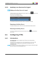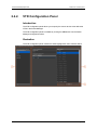
1
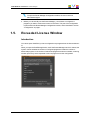
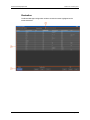
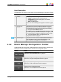
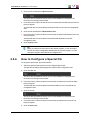
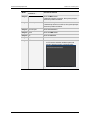
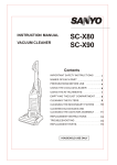
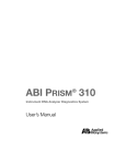
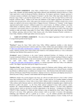
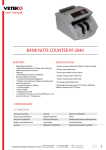
USER MANUAL
Router Manager
Version 6.0 - January 2014
USER MANUAL IPAirEdit 6.0 Router Manager
Copyright
EVS Broadcast Equipment SA– Copyright © 2014. All rights reserved.
Disclaimer
The information in this manual is furnished for informational use only and subject to
change without notice. While every effort has been made to ensure that the information
contained in this user manual is accurate, up-to-date and reliable, EVS Broadcast
Equipment cannot be held responsible for inaccuracies or errors that may appear in this
publication.
Improvement Requests
Your comments will help us improve the quality of the user documentation. Do not
hesitate to send improvement requests, or report any error or inaccuracy on this user
manual by e-mail to [email protected].
Regional Contacts
The address and phone number of the EVS headquarters are usually mentioned in the
Help > About menu in the user interface.
You will find the full list of addresses and phone numbers of local offices either at the end
of this user manual (for manuals on hardware products) or at the following page on the
EVS website: http://www.evs.com/contacts.
User Manuals on EVS Website
The latest version of the user manual, if any, and other user manuals on EVS products
can be found on the EVS download center, on the following webpage:
http://www.evs.com/downloadcenter.
I
USER MANUAL IPAirEdit 6.0 Router Manager
Table of Contents
TABLE OF CONTENTS
III
WHAT'S NEW?
V
1.
1
INTRODUCTION
1.1. Product Overview
1
1.2. Typical Workflow
1
1.3. Prerequisites
4
1.4. Initializing the Router Manager
4
1.5. Exceeded License Window
5
2.
7
CONFIGURATION
2.1. Introduction
7
2.2. Router Manager Configuration Window
7
2.2.1. Overview of the Router Manager Configuration Window
2.2.2. Router Manager Configuration Toolbar
2.2.3. List of Router Devices
2.3. Configuring Programs
11
11
2.3.2. Program Configuration Panel
12
2.3.3. How to Configure a Program for Ingest
13
2.3.4. How to Configure a Program for Playout
16
2.3.5. Auxiliary Live Sources for Ingest
19
19
2.4.1. Introduction
19
2.4.2. VTR Configuration Panel
20
2.4.3. How to Configure a VTR
21
2.5. Configuring CGs
Table of Contents
9
10
2.3.1. Introduction
2.4. Configuring VTRs
3.
7
22
2.5.1. Introduction
22
2.5.2. CG Configuration Panel
23
2.5.3. How to Configure a CG
24
2.5.4. How to Configure a Special CG
25
OPERATION
26
3.1. Overview of the Router Manager Window
26
3.2. Locking/Unlocking Sensitive Areas
28
3.3. Switching the Active Sources
29
III
USER MANUAL IPAirEdit 6.0 Router Manager
What's New?
In the user manual, the icon
has been added on the left margin to highlight
information on new and updated features.
The sections updated to reflect the new and modified features on Router Manager from
IPAirEdit6.0 (compared to IPAirEdit 5.98) are listed below.
Use of a video router in Ingest Recovery mode
A video router can be used with IPAirEdit to increase the number of incoming feeds
manageable by EVS server recorder channels.
•
See section "Product Overview" on page 1.
•
See section "Typical Workflow " on page 1.
•
See section "Introduction" on page 11.
•
See section "Program Configuration Panel" on page 12.
•
See section "How to Configure a Program for Ingest" on page 13.
•
See section "Auxiliary Live Sources for Ingest" on page 19.
•
See section "Overview of the Router Manager Window" on page 26.
•
See section "Switching the Active Sources" on page 29.
Program Configuration Panel
The Program Configuration panel display and the way to configure programs has changed.
•
See section "Program Configuration Panel" on page 12.
•
See section "How to Configure a Program for Playout" on page 16.
Setting Display
The General setting has been moved to the main Router Manager Configuration window
(List of devices).
•
What's New?
See section "Overview of the Router Manager Configuration Window" on page 7.
V
USER MANUAL IPAirEdit 6.0 Router Manager
1.
Introduction
1.1.
Product Overview
The Router Manager is a module used in association with the IPAirEdit application. See
the IPAirEdit user manual for more information on IPAirEdit.
The Router Manager aims at controlling the video router (through the router controller)
used on an IPAirEdit workflow that provides redundancy.
The Router Manager module has been designed to control specifically the Miranda router
by sending commands to the Miranda NV9000 router controllers.
Depending on the configuration of the installation, the Router Manager can be configured
in Playout mode or in Ingest / Recovery mode.
1.2.
Typical Workflow
Illustration - Ingest / Recovery Mode
The following diagram shows the part of an IPAirEdit setup dedicated to the router
management in Ingest / Recovery mode, and how the different sources and destinations
are configured for each content control channel.
In this workflow, the video router increases the number of sources which can be input into
a server destination.
1. Introduction
1
EVS Broadcast Equipment SA
Issue 6.0.B - January 2014
Illustration - Playout Mode
The following diagram shows the part of an IPAirEdit setup dedicated to the router
management in Playout mode, and how the different sources and destinations are
configured for each content control channel. The various devices and the communication
processes are described below.
In this workflow, the video router increases the number of sources which can be routed to
the transmission channel (TX channel).
Sources (1) and Destinations (2) on the Video Router
Source and destination channels are configured on the ports of the video router as follows.
In Ingest / Recovery Mode
The A/V content which can be routed to router IN ports and configured as sources in the
router database are:
•
the live channel
•
the A/V content from different VTR devices
The router output is connected to a single destination, called DEDEC in the Router
Manager Configuration window, which is itself routed to the main and backup servers.
2
1. Introduction
USER MANUAL IPAirEdit 6.0 Router Manager
In Playout Mode
The A/V content which can be routed to router IN ports and configured as sources in the
router database are:
•
the delayed and edited channels (PGM1) of the main and backup EVS servers.
•
the live channel to broadcast
•
the A/V content from a VTR device
•
several CG channels delivered by a character generator device.
The router output is connected to a single destination, called DEDEC in the Router
Manager Configuration window, which is itself routed to the main and backup servers.
The router destinations can be
•
the TX channels
•
the CG destinations, which are then sent to the inputs of CG devices, as the operator
should have the possibility to add graphics to each play channel (main and backup) of
each channel to broadcast.
Router Manager (3)
The Router Manager is a module of IPAirEdit that has to be installed on one or more
IPDirector workstations. It allows controlling which transmission signal the router will
send.
The Router Manager cannot start if the Router Manager service is not running on the same
workstation.
Router Controllers Controlled through GigE Network (4)
The Router Manager does not control the router directly, but throughout two router
controllers (one for main and one for backup) connected to the setup via the GigE network.
The Router Manager module therefore acts as a control panel of the router controllers,
allowing users to take the control of the video router through the router controllers.
Router Manager Service (5)
The Router Manager service
is launched on the IPDirector workstations where the
Router Manager application will be started.
When an operator executes a failover from the AirEdit module, or switches the active
source from the Router Manager, IPAirEdit uses the Router Manager service to exchange
commands and requests with the couple of router controllers.
In a workflow with redundancy, it is recommended to start the Router Manager service
and the Router Manager on two IPDirector workstations running the IPAirEdit
applications. Both Router Manager services will send the same commands. If one fails,
the second one is the backup.
1. Introduction
3
EVS Broadcast Equipment SA
1.3.
Issue 6.0.B - January 2014
Prerequisites
Before you can use IPAirEdit Router Manager, you need to perform the following
installation and configuration tasks.
Installing and Configuring the IPAirEdit Redundant Setup
1. Installing the IPAirEdit application on the main and backup IPDirector workstations
and define the workstations as master candidates.
2. Configuring the redundancy on IPAirEdit setup.
See the IPAirEdit configuration guide for full details on IPAirEdit configuration. Refer
to the EVS Project Manager.
Organizing the Connections Between the Router and the
IPAirEdit Setup
1. Setting up the physical connections between the EVS servers and the router.
2. Configuring the Router Manager service in the Remote Installer and in the router
controllers.
3. Installing the XSecure licenses for the Router Manager and Router Manager
Configuration modules.
1.4.
Initializing the Router Manager
To initialize the Router Manager, proceed as follows:
1. From the Windows task bar, right-click the Router Manager service icon , and click
Start Service from the contextual menu. When the Router Manager service is started
and ready, the icon turns green
.
2. Launch IPAirEdit.
Note
You cannot open IPAirEdit if you have configured more programs than the
license allows it to. Should the number of configured programs exceeds what is
allowed, you will be requested to remove the exceeding programs from the
configuration. See section "Exceeded License Window" on page 5 for more
information.
At this stage, the Router Manager and Router Manager Configuration icons are
available in the main application bar, and you can access each module by clicking the
corresponding icon.
4
1. Introduction
USER MANUAL IPAirEdit 6.0 Router Manager
Note
To open the Router Manager Configuration module, the user must have
administrator rights.
3. Before you can actually use the Router Manager, you still have to configure the
programs you want to monitor and control on the router. This part of the configuration
is performed in the Router Manager Configuration module, and is described in section
"Configuration" on page 7.
1.5.
Exceeded License Window
Introduction
You cannot open IPAirEdit if you have configured more programs than the license allows it
to.
When you open the IPAirEdit application, and if the Router Manager service is started, the
system controls whether the number of configured programs exceeds the number of
authorized programs. If the number of authorized programs has been exceeded, a warning
window opens and you are requested to remove programs from the configuration.
1. Introduction
5
EVS Broadcast Equipment SA
Issue 6.0.B - January 2014
How to Remove Programs from the Configuration?
To remove programs from the Exceeded License window, proceed as follows:
1. From the list of configured programs, click the program to be removed from the
configuration. Use CTRL + click to select multiple programs at the same time.
2. Click the Remove button. The selected programs are removed and the number of
exceeding programs is re-computed.
OR
Click the Close button. The window will only close if you have removed at least the
requested number of programs from the configuration.
3. Restart the Router Manager service by right-clicking the Router Manager service
icon in the Windows task bar, and by clicking Restart Service from the contextual
menu.
6
1. Introduction
USER MANUAL IPAirEdit 6.0 Router Manager
2.
Configuration
2.1.
Introduction
Purpose
The Router Manager Configuration module allows you to define whether a program will be
configured for Ingest, for Playout, or both, to associate different sources and a destination
to a program, to configure the VTR sources that are available on each program, as well as
each couple of CG sources and destinations that will be associated to a specific program
in the configuration.
Opening the Router Manager Configuration Module
To open the Router Manager Configuration module, click the
icon in the main application bar.
The Router Manager Configuration window opens.
Note
To open the Router Manager Configuration module, the user must have
administrator rights.
2.2.
Router Manager Configuration
Window
2.2.1.
Overview of the Router Manager
Configuration Window
Description
All the configuration operations are performed from this window. The lower pane always
remains the same, while the upper pane can display different views according to the
selection made in the toolbar.
At window opening, the upper pane shows the list of router devices.
2. Configuration
7
EVS Broadcast Equipment SA
Issue 6.0.B - January 2014
Illustration
The Router Manager Configuration window contains the areas highlighted on the
screenshot below:
8
2. Configuration
USER MANUAL IPAirEdit 6.0 Router Manager
Area Description
The table below describes the various parts of the Router Manager Configuration window:
2.2.2.
Area
Description
1.
Toolbar
The toolbar provides 3 categories of buttons:
• Display: to display the list of router devices
• Configuration: to open the Program, VTR and CG
configuration panels
• Exit: to exit the window
See section "Router Manager Configuration Toolbar" on page
9.
2.
List of router
devices
This area shows the list of all devices defined in the router
database.See section "List of Router Devices" on page 10.
It is displayed in the upper pane at opening of the window, or
by clicking the List of Devices button.
By clicking one of the Configuration buttons from the toolbar,
this area displays panels used to configure the Program, VTR
or CG. See sections "Program Configuration Panel" on page
12, "VTR Configuration Panel" on page 20, and "CG
Configuration Panel" on page 23.
3.
General option
This option is used to make the Lock/Unlock Destination
button available to users in the Router Manager module.
This is a general setting applied to all programs.
Router Manager Configuration Toolbar
The Router Manager Configuration toolbar features the following buttons, and allows the
following actions. This toolbar remains available in all Configuration panels.
Button
Action
Displays the list of router devices.
See section "List of Router Devices" on page 10.
Displays the Program Configuration panel.
See section "Program Configuration Panel" on page 12.
Displays the VTR Configuration panel.
See section "VTR Configuration Panel" on page 20.
Displays the CG configuration panel.
See section "CG Configuration Panel" on page 23.
2. Configuration
9
EVS Broadcast Equipment SA
Button
Issue 6.0.B - January 2014
Action
Closes the Router Manager Configuration window.
Logs off the current user from the main application, and returns to
the login window.
Exits the main application.
2.2.3.
List of Router Devices
Introduction
The list of router devices is displayed by default when you open the Router Manager
Configuration window. When a configuration panel is open, you can come back to the list
of router devices by clicking the List of Devices button in the toolbar at the bottom of the
window.
The list of router devices displays the devices configured in the router database, and
related information.
Description
10
2. Configuration
USER MANUAL IPAirEdit 6.0 Router Manager
The list of router devices contains several data presented in columns. The table below
describe each of these columns:
Column
Description
DeviceID
Device ID.
Device Mnemonics Name of the device as configured in the router database.
Level
Device level.
The devices are defined as sending and receiving signals on
certain levels. A level is typically SD, HD, analog video, AES,
analog audio, or machine control.
The level is always set to 0 (HD).
Configured in the
Router Manager
Status about whether the given device has been configured or not
in the Router Manager Configuration window.
The possible values are True or False.
Program/CG/VTR
If the device corresponds to a program, the name of the program
will be displayed.
If the device does not correspond to a program, the device
category is displayed: CG, CRS/TS, or VTR.
Source/Destination Type of connection to the router.
The device can be configured either as a source (INPUT) or as a
destination (OUTPUT) of the router.
Name
Name of the button associated to the source device, as it will be
displayed in the Router Manager.
2.3.
Configuring Programs
2.3.1.
Introduction
This chapter explains how to configure the sources and destinations of a program
connected to the router for the Router Manager module.
You perform such a configuration in the Program Configuration panel. See section
"Program Configuration Panel" on page 12 for more information on the areas in the
Program Configuration panel.
A program can be configured for Playout, for Ingest / Recovery, or both.
Once configured, the program will automatically be available in the Router Manager, with
the underlying connections to the right devices.
For each program to configure for Playout, you need to specify at least three devices:
2. Configuration
•
A source device for the main program, that is the delayed and edited channel/output
from the main EVS server.
•
A source device for the backup program, that is the delayed and edited channel/output
from the backup EVS server.
•
A destination device, that is the transmission channel.
11
EVS Broadcast Equipment SA
Issue 6.0.B - January 2014
Configuring a destination device for the live program, that is the incoming program feed, is
optional.
Note
If the router destination has not been locked, when an AirEdit operator clicks the
FAIL OVER button, the system performs the failover and switches
automatically the active sources. The displays in the Router Manager interface
are updated accordingly. The new sources sent to TX and to the CG destination
should have been configured before the failover operation so that they
correspond to the currently active server output.
2.3.2.
Program Configuration Panel
Description
The Program Configuration panel allows users to specify whether a program is configured
in Ingest/Recovery mode, in Playout mode or both, and to specify which devices
associated to the router are the router sources and destination.
The Program Configuration panel is available by clicking the Program button from the
Router Manager Configuration toolbar.
lllustration
The Program Configuration panel contains the areas highlighted on the screenshot below:
12
2. Configuration
USER MANUAL IPAirEdit 6.0 Router Manager
Area Description
The table below describes the various parts of the Program Configuration panel:
2.3.3.
Area
Description
1.
Lists of Programs
This area can display two different views:
• Add a Program: shows the list of programs created in
the Program Manager but not yet configured for the
Router Manager.
This is the view shown when no program has been
configured for the Router Manager yet.
•
Managed Programs: shows the list of programs
configured for the Router Manager. A green bullet icon
features their configuration mode.
The program configuration is done or modified from this
view.
From both views, a button is available to switch to the other
view. This is a Managed Programs button in the Add a
Program view, or a Add a Program button in the Managed
Programs view.
2.
Configuration area
This area is used to configure a program selected in the
Managed Programs list. It contains the list of source types
(a), the list of destination types (b) and the list of available
devices (c).
It displays the settings of the configured program currently
selected.
3.
Program
configuration
toolbar
This toolbar allows you to save or delete the current
configuration, or to cancel any modification.
How to Configure a Program for Ingest
To configure a program for the first time, proceed as follows:
1. Select the program from the Add a Program pane.
The left pane of the Router Manager Configuration window switches to the Managed
Programs pane.
The program button is highlighted.
2. Configuration
13
EVS Broadcast Equipment SA
Issue 6.0.B - January 2014
2. Click the Ingest Recovery button.
The Ingest Recovery button is highlighted. The bullet icons are both red as the
program has not yet been configured in one mode or the other.
To assign a live train as source type: proceed with steps 3 and 4, otherwise go to step 5.
3. In the Source Configuration area, select Live or add an auxiliary source as explained
in section "Auxiliary Live Sources for Ingest" on page 19.
Note
VTR sources cannot be selected here as they cannot be associated to a
specific program. If required, users will be able to select them from the Router
Manager window.
The list of available devices is displayed in the Devices list on the right of the window.
Note
A source can be assigned several times.
14
2. Configuration
USER MANUAL IPAirEdit 6.0 Router Manager
4. In the Devices list, select the device to be used as the selected source (VTR or Live)
for the program being configured.
The selected device is associated to the selected source in the Source Configuration
area.
5. In the Destination Configuration area, select a destination type: DEDEC is the only
option.
The list of devices is displayed in the Devices list on the right of the window.
Note
A destination can only be assigned once.
6. In the Devices list, select the device to be used as XXX for the program being
configured. Devices displayed in italicized and grayed text are not available.
The selected device is associated to the selected destination in the Source
Configuration area.
2. Configuration
15
EVS Broadcast Equipment SA
Issue 6.0.B - January 2014
7. Click the Save button.
A green icon is displayed on the Ingest Recovery button of the configured program in
the Managed Programs pane.
2.3.4.
How to Configure a Program for Playout
To configure a program for playout, proceed as follows:
1. Select the program from the Add a Program pane.
The left pane of the Router Manager Configuration window switches to the Managed
Programs pane.
The program button is highlighted.
2. Click the Playout button.
By default, the Playout mode is already selected and the Playout button is
highlighted. The bullet icons are both red as the program has not yet been configured
in one mode or the other.
16
2. Configuration
USER MANUAL IPAirEdit 6.0 Router Manager
3. In the Source Configuration area, select a source type, for example Main (or Backup
or Live).
The list of available devices is displayed in the Devices list on the right of the window.
Note
A source can be assigned several times.
4. In the Devices list, select the device to be used as the selected source (main server,
backup server, or live) for the program being configured.
The selected device is associated to the selected source in the Source Configuration
area.
5. Repeat steps 3 and 4 for the Backup source type.
6. (optional) Repeat steps 3 and 4 for the Live source type.
2. Configuration
17
EVS Broadcast Equipment SA
Issue 6.0.B - January 2014
7. In the Destination Configuration area, select a destination type: TX is the only option.
The list of devices is displayed in the Devices list on the right of the window.
Note
A destination can only be assigned once.
8. In the Devices list, select the device to be connected to the transmission channel for
the program being configured. Devices displayed in italicized and grayed text are not
available.
The selected device is associated to the selected destination in the Source
Configuration area.
9. Click the Save button.
A green icon is displayed on the Playout button of the configured program in the
Managed Programs pane.
18
2. Configuration
USER MANUAL IPAirEdit 6.0 Router Manager
2.3.5.
Auxiliary Live Sources for Ingest
Adding an Auxiliary Source for Ingest
To add an auxiliary source to the list of sources for Ingest, click the
top of the Source Configuration area.
button from the
The new source is named Live - Aux nr
It is automatically selected and the list of devices is displayed on the right.
Renaming an Auxiliary Source
To rename an auxiliary source, click in the source name field and modify the name.
Removing an Auxiliary Source
To remove an auxiliary source from the list of sources, click the
source name.
2.4.
Configuring VTRs
2.4.1.
Introduction
button next to the
This chapter explains how to configure a new VTR source or to edit an existing
VTR configuration.
You perform such a configuration in the VTR Configuration panel. See section "VTR
Configuration Panel" on page 20 for more information on the areas in the VTR
Configuration panel.
The configured VTR devices will be available as sources for Playout mode and for Ingest /
Recovery mode from the Router Manager window.
2. Configuration
19
EVS Broadcast Equipment SA
2.4.2.
Issue 6.0.B - January 2014
VTR Configuration Panel
Introduction
The VTR Configuration panel allows you to specify the source devices to be defined as
VTRs in the Router Manager.
The VTR Configuration panel is available by clicking the VTR button from the Router
Manager Configuration toolbar.
Illustration
The VTR Configuration panel contains the areas highlighted on the screenshot below:
20
2. Configuration
USER MANUAL IPAirEdit 6.0 Router Manager
Area Description
The table below describes the various parts of the VTR Configuration panel:
2.4.3.
Area
Description
1.
List of
configured
VTRs
This list displays all VTRs that have been configured within the
Router Manager.
The Add button at the bottom of the area allows users to
configure a new VTR.
2.
VTR
configuration
area
This area allows users to assign a VTR device to a VTR name in
the Router Manager, and, if requested, to rename a VTR.
3.
VTR
configuration
toolbar
This toolbar allows you to save or delete the current configuration,
or to cancel any modification.
How to Configure a VTR
To configure a VTR, proceed as follows:
1. To edit an existing VTR configuration:
◦
select the VTR number from the list of configured VTRs.
The VTR settings are displayed in the VTR Configuration area.
OR
To configure a new VTR:
◦
click the Add button at the bottom of the list of configured VTRs.
A VTR number is added to the list, and empty settings are displayed in the
VTR Configuration area.
2. (optional) To rename a VTR, modify the name in the Rename VTR field, as you want
it to be displayed in the Router Manager operating window.
3. To assign a VTR device to the VTR number, click the VTR row in the Source
Configuration area.
The list of devices defined as a source in the router database is displayed in the
Devices list on the right of the window.
2. Configuration
21
EVS Broadcast Equipment SA
Issue 6.0.B - January 2014
4. In the Devices list, select the VTR device to be used as the selected source for the
VTR being configured.
The selected VTR device is associated to the selected source in the Source
Configuration area.
5. Click the Save button.
2.5.
Configuring CGs
2.5.1.
Introduction
This chapter explains how to configure the sources and destinations for the CG of a given
program for the Router Manager module, and to modify the parameters for the Special
CGs.
You perform such a configuration in the CG Configuration panel.See section "CG
Configuration Panel" on page 23 for more information on the areas in the CG Configuration
panel.
You can configure two types of CG:
The Special CGs consist of a fixed predefined text that can be sent on air in specific
cases (for example technical problem, temporary program disruption, ...). They are the
same for all programs.
The standard CGs are program-specific. For a given program, you need to specify two
device connections:
•
CG source: this is a router source device (the source represents the connection from
the CG device to the router).
This is the program main or backup source including the graphics that is sent back to
the router.
•
CG destination: this is a router destination device (the destination represents the
connection from the router into the CG device.
This is the program main or backup source that is sent out of the router to the CG
device. The program main or backup source is automatically selected as a source for
the CG destination when the user performs a failover from the AirEdit Edition panel or
from the Router Manager interface.
Note
If the router destination has not been locked, when an AirEdit operator clicks the
FAIL OVER button, the system performs the failover and switches
automatically the active sources. The displays in the Router Manager interface
are updated accordingly. The new sources sent to TX and to the CG destination
should have been configured before the failover operation so that they
correspond to the currently active server output.
22
2. Configuration
USER MANUAL IPAirEdit 6.0 Router Manager
2.5.2.
CG Configuration Panel
Introduction
The CG Configuration panel allows you to specify the source devices to be defined as
CGs in the Router Manager.
The CG Configuration panel is available by clicking the CG button from the Router
Manager Configuration toolbar.
Illustration
The CG Configuration panel contains the areas highlighted on the screenshot below:
2. Configuration
23
EVS Broadcast Equipment SA
Issue 6.0.B - January 2014
Area Description
The table below describes the various parts of the CG Configuration panel:
2.5.3.
Area
Description
1.
List of Special
CGs
This area allows to display the Special CG Configuration area, in
order to configure the CRS/TS.
2.
List of
configured
CGs
This list displays all CGs that have been configured within the
Router Manager.
The Add button at the bottom of the area allows users to
configure a new CG.
3.
Configuration
area
This area can display two different views depending on the
CG/Special CG selected on the left pane:
• The Special CG Configuration area is displayed when a
Special CG is selected in the List of configured Special CGs.
It allows users to assign another source device to a specific
type of CG (CRS or TS) available in the Router Manager.
• The CG Configuration area is displayed when a CG is
selected in the List of configured CGs.
It is used to specify the source and destination connections to
the CG device for a given program.
4.
CG
Configuration
toolbar
This toolbar allows you to save or delete the current configuration,
or to cancel any modification.
How to Configure a CG
To configure a CG, proceed as follows:
1. To edit an existing CG configuration,
◦
select it from the list of configured CGs.
The CG settings are displayed in the CG Configuration area.
OR
To configure a new CG,
◦
click the Add button at the bottom of the list of configured CGs.
A CG number is added to the list, and empty settings are displayed in the
CG Configuration area.
2. (optional) To rename a CG, modify the name in the Rename CG field, as you want it
to be displayed in the Router Manager operating window.
3. From the list of configured programs, click the program to associate to the CG
configuration. This is the list of programs configured for Playout.
24
2. Configuration
USER MANUAL IPAirEdit 6.0 Router Manager
4. Click the CG row below the CG Source label.
The list of devices defined as a source in the router database is displayed in the
Devices list on the right of the window.
5. In the Devices list, select the CG device to be used as the selected source for the CG
being configured.
The selected device is associated to the selected CG source in the CG Configuration
area.
6. Click the CG row below the CG Destination label.
7. In the Devices list, select the device to be used as the selected destination for the CG
being configured.
The selected device is associated to the selected CG destination in the CG
Configuration area.
8. Click the Save button.
Tip
When you need to use a CG device with another program, you do not need to
remove the current configuration and add a new CG for this program. You can
change the program associated to the configured CG.
2.5.4.
How to Configure a Special CG
To configure a Special CG, proceed as follows:
1. Select the Special CG line from the list of configured Special CG.
The Special CG settings are displayed in the Special CG Configuration area.
2. Click the CRS row.
The list of devices defined as a source in the router database is displayed in the
Devices list on the right of the window.
3. In the Devices list, select the device to be used as the selected source for the CRS
being configured.
The selected device is associated to the selected CRS source in the Special CG
Configuration area.
4. Click the TS row.
The list of devices defined as a source in the router database is displayed in the
Devices list on the right of the window.
5. In the Devices list, select the device to be used as the selected source for the TS
being configured.
6. Click the Save button.
2. Configuration
25
EVS Broadcast Equipment SA
Issue 6.0.B - January 2014
3.
Operation
3.1.
Overview of the Router Manager
Window
Purpose
The Router Manager window allows users to monitor up to six different program routes,
and to switch manually the router sources.
Prior to using the Router Manager, you have to configure the programs you want to
monitor in the Router Manager. The configuration is performed in the Router Manager
Configuration module. See section "Configuration" on page 7.
To open the Router Manager window, click the
button from the main
application bar. Two Router Manager windows can be opened at the same time, allowing
to monitor twelve program routes.
Illustration
The Router Manager window is divided into 6 panels. Each panel is dedicated to one
program. The screenshot below features a single panel, as all fields or buttons have the
same purpose or meaning in all panels, even if they are configured specifically to the
program.
26
3. Operation
USER MANUAL IPAirEdit 6.0 Router Manager
Area Description
3. Operation
Area/Field
Description
1.
Program
Name field
This filed displays the name of the program to route.
Clicking the program name allows users to select the program
to be displayed in the panel.
2.
Lock button
This button allows users to lock the program selection, and
prevent accidental change of the selected program.
See section "Locking/Unlocking Sensitive Areas" on page 28.
3.
Main and
This area displays the statuses of the main and backup EVS
Backup Server servers, as well as their synchronization status.
See the IPAirEdit User Manual for detailed information about
Status area
the possible displays.
4.
Router Switch This area contains 2 tabs and displays the one or those
Manager panel corresponding to the mode used to configure the selected
program: Playout and/or Ingest Recovery.
In Playout mode, this area is used to switch manually the
router source to:
• the main server,
• the backup server,
• the live event,
• the VTR,
• the CG,
• the CRS,
• the TS.
In Ingest Recovery mode, this area is used to switch manually
the router source to:
• Live Playout,
• a VTR device.
See section "Switching the Active Sources" on page 29.
This panel can be locked/unlocked.
5.
Lock zone
This zone provides two toggle buttons:
• Lock Panel: to lock/unlock the router switch manager
panel of the Router Manager module. This prevents an
operator from any handling mistake (especially when using
the application through a touch screen).
• Lock Destination: to lock/unlock the destination on the
third-party router. This prevents an operator from
accidentally taking a source to a particular destination.
See section "Locking/Unlocking Sensitive Areas" on page 28.
27
EVS Broadcast Equipment SA
Issue 6.0.B - January 2014
Button Formats and Color Codes
The buttons allowing to select a source for the router can have the following formats:
3.2.
Button Format
Meaning
Blue
The status is ok and the selected source is the active one.
Light gray
The status is ok and the selected source is not the active one.
Red
The status is not ok.
Dimmed
The source is not configured.
Locking/Unlocking Sensitive Areas
Introduction
To prevent any handling mistake (especially when using the application through a touch
screen), some sensitive areas of the window can be locked out.
How to Lock/Unlock the Channel/Program Name
Selection?
Toggle the Lock/Unlock button from the program/channel name area.
When locked, the display is as follows:
How to Lock/Unlock the Panel?
Toggle the Lock Panel button from the router switch manager panel.
When locked, the display is as follows:
28
3. Operation
USER MANUAL IPAirEdit 6.0 Router Manager
How to Lock/Unlock the Channel/Program Destination?
Toggle the Lock Destination button from the router switch manager panel.
When locked, the display is as follows:
The user can lock/unlock the destination throughout a third-party control panel, or directly
on the NV9000. The status of the Lock Destination button will be updated accordingly.
Note
The destination can be locked from the router switch manager panel
• if the panel itself is not locked, and
• if the setting has been enabled in the Program Configuration panel of the
Router Manager Configuration window. See section "Program Configuration
Panel" on page 12.
3.3.
Switching the Active Sources
Introduction
In the Router Manager, you can switch the source sent to the main and backup servers (in
Ingest Recovery mode) or sent on air (in Playout mode) by clicking the button
corresponding to the requested source in the Router Switch Manager area.
When you have selected the source to be sent to EVS servers (Ingest) or to go on air
(Playout), the system sends a switch command to the router controller, and, if there is no
source or destination issue, it switches the router position to send media to the
EVS servers or to play on air the selected source.
Note
To switch manually the active sources, the Router Switch Manager panel must
be unlocked.
How to Switch the Active Sources?
3. Operation
Mode
To switch the active
Proceed as follows
source to ...
Ingest
the live input
Click the Live PLayout button.
Ingest
a VTR device
Click one of the VTR button.
29
EVS Broadcast Equipment SA
Mode
Issue 6.0.B - January 2014
To switch the active
Proceed as follows
source to ...
Playout the main server
Click the Main button.
If the main server is not active, the system prompts
the user to perform a failover.
Playout the backup server
Click the Backup button.
If the backup server is not active, the system prompts
the user to perform a failover.
Playout the live input
Click the Live button.
Playout CRS
Click the CRS button.
Playout TS
Click the TS button.
Playout CG
Click the CG button.
Playout VTR
1. Click the VTR button.
A VTR source selection window opens and
displays buttons for each configured VTR:
2. Click the VTR source you want to switch to.
30
3. Operation
Corporate
+32 4 361 7000
North & Latin America
+1 973 575 7811
EVS Headquarters
Liège Science Park
16, rue Bois St Jean
B-4102 Seraing
Belgium
To learn more about EVS go to www.evs.com
Asia & Pacific
+852 2914 2501
Other regional offices
www.evs.com/contact
EVS Broadcast Equipment is continuously adapting and improving its products in accordance with the ever changing
requirements of the Broadcast Industry.
The data contained herein is therefore subject to change without prior notice. Companies and product names are
trademarks or registered trademarks of their respective companies.