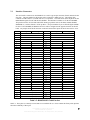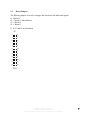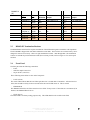
1
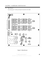
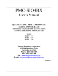
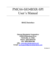
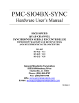
SIO4B-FO
User’s Manual
QUAD CHANNEL RS-485
SERIAL to FIBER OPTIC CONVERTER
General Standards Corporation
8302A Whitesburg Drive
Huntsville, AL 35802
Phone: (256) 880-8787
Fax: (256) 880-8788
URL: www.generalstandards.com
E-mail: [email protected]
Revision NR
PREFACE
Revision History
Additional copies of this manual or other General Standards Corporation literature may be obtained
from:
General Standards Corporation
8302A Whitesburg Drive
Huntsville, Alabama 35802
Telephone: (256) 880-8787
Fax: (256) 880-8788
URL: www.generalstandards.com
The information in this document is subject to change without notice.
General Standards Corporation makes no warranty of any kind with regard to this material, including,
but not limited to, the implied warranties of merchantability and fitness for a particular purpose. Although
extensive editing and reviews are performed before release to ECO control, General Standards
Corporation assumes no responsibility for any errors that may exist in this document. No commitment
is made to update or keep current the information contained in this document.
General Standards Corporation does not assume any liability arising out of the application or use of
any product or circuit described herein, nor is any license conveyed under any patent right of any rights
of others.
General Standards Corporation assumes no responsibility resulting from omissions or errors in this
manual, or from the use of information contained herein.
General Standards Corporation reserves the right to make any changes, without notice, to this product
to improve reliability, performance, function, or design.
All rights reserved
No parts of this document may be copied or reproduced in any form or by any means without prior
written consent of General Standards Corporation.
Copyright © 2007 General Standards Corporation
RELATED PUBLICATIONS
EIA-422-A – Electrical Characteristics of Balanced Voltage Digital Interface Circuits
(EIA order number EIA-RS-422A)
EIA-485 – Standard for Electrical Characteristics of Generators and Receivers for Use in Balanced Digital
Multipoint Systems
(EIA order number EIA-RS-485)
EIA Standards and Publications can be purchased from:
GLOBAL ENGINEERING DOCUMENTS
15 Inverness Way East
Englewood, CO 80112
Phone: (800) 854-7179
http://global.ihs.com/
TABLE OF CONTENTS
CHAPTER 1: INTRODUCTION ....................................................................................................................... 1
1.0
1.1
1.1.2
1.1.5
1.1.8
GENERAL DESCRIPTION............................................................................................................................ 1
FUNCTIONAL DESCRIPTION....................................................................................................................... 1
CONTROL LOGIC ................................................................................. ERROR! BOOKMARK NOT DEFINED.
RS422/RS485 TRANSCEIVERS .................................................................................................................. 3
CONNECTOR INTERFACE .......................................................................................................................... 3
CHAPTER 2: HARDWARE CONFIGURATION ............................................................................................ 4
5.0
5.2
5.3
5.4
BOARD LAYOUT....................................................................................................................................... 4
INTERFACE CONNECTORS ......................................................................................................................... 5
RS485/RS422 TERMINATION RESISTORS ............................................. ERROR! BOOKMARK NOT DEFINED.
JUMPERS
CHAPTER 6: ORDERING OPTIONS............................................................................................................. 10
6.0
ORDERING INFORMATION ....................................................................................................................... 10
6.0.2
6.1
6.2
6.3
TRANSCEIVER ........................................................................................................................................ 10
INTERFACE CABLE ................................................................................................................................. 10
DEVICE DRIVERS ................................................................................ ERROR! BOOKMARK NOT DEFINED.
CUSTOM APPLICATIONS ...................................................................... ERROR! BOOKMARK NOT DEFINED.
CHAPTER 1: INTRODUCTION
1.0
General Description
The SI04B-FO Serial to Fiber Optic Converter was designed to convert RS-485/422 signals to Fiber Optic in order
to extend their distance. The I/O cable interface was specifically designed to be compatible with General
Standards’ SIO4 serial I/O product family but will also work with generic serial I/O. The RS-485 transceivers
provide four fully independent synchronous or asynchronous serial channels. Each channel consists of 4 RS485/422 pairs.
Features:
-pin SCSI-3 connector for serial connections. Adapter cable
(SCSI-3 to 4x DB25s) available upon request. 68-pin SCSI-3 connector is compatible with General Standards’
Serial IO Cards such as the XXX-SIO4B/SIO4BX/SIO4BXR and SYNC products.
MODE 1: When used with the SIO4BXR-FO board, this makes a complete IO solution. The SIO4BXRFO board provides the PCI host interface, Zilog Z16C30 Universal Serial Controllers (USC), FIFOs and
fiber optic transceivers. The Serial to Fiber Optic Converter Box takes the Fiber Optic signals and
converts them into standard serial signals as listed below.
MODE 2: Boxes can be used, back-to-back to make up a serial to fiber (and then back to serial) extension
product.
g SIO4BXR boards or any generic serial IO controller product
1.1
Functional Description
A functional block diagram of the SIO4B-FO is shown in Figure 1-1. A high density 68-pin SCSI-3 connector is
used to connect to the RS485/422 transceivers. The pinouts of this connector are compatible with most of the GSC
serial IO products in the SIO4B family. Breakout cables can be used to convert the 68-in connector to DB25s or
whatever is desired.
RS-485/422
Serial I/O
Transceivers
RS-485/422
Serial I/O
Transceivers
FPGA
HIGH DENSITY 68-PIN
SCSI CONNECTOR
SERDES
Fiber Optic
Transceiver
RS-485/422
Serial I/O
Transceivers
RS-485/422
Serial I/O
Transceivers
Figure 1-1 Block Diagram of SIO4B-FO
Figure 1-2 shows the SIO4B-FO board connected to the PCI-SIO4BXR-FO board. The PCI board provides the PCI
host interface, Zilog Z16C30 Universal Serial Controllers (USC), FIFOs and fiber optic transceivers. The fiber
optics then interface to the Serial to Fiber Optic Converter Box. This allows for operating many serial channels at
high speeds and at long distances.
SCSI to DB25 Cable
Host Bus
SIO4BXR-FO
Board
Fiber Optic Cables
Serial to FO
Converter Box
Figure 1-2 SIO4B-FO Used with PCI-SIO4BXR-FO
Figure 1-3 shows the SIO4B-FO board connected “back to back” to provide for a serial to fiber optic (and back to
serial) extension product. This product will be used in this mode when interfacing to existing product in order to
extend the distance.
PCI-SIO4B User Manual, Revision: E.1
General Standards Corporation
8302A Whitesburg Drive Huntsville, AL 35802, Phone: (256) 880-8787
2
SCSI to DB25 Cable
General
Standards
Serial IO
Board
SCSI Cable
Serial to FO
Converter Box
Fiber Optic Cables
Serial to FO
Converter Box
Figure 1-3 SIO4B-FO Used “Back to Back”
1.1.5 RS422/RS485 Transceivers
Industry standard differential RS485 signaling allows for longer, faster, and more reliable data connections.
Socketed termination resistors allow the board to comply with both RS485 and RS422 terminations, or they may be
removed for a multi-drop configuration. All RS22/RS485 transceivers are bi-directional, so that any pin may be
configured to receive or transmit. This allows the user more flexibility for wiring cable connections
1.1.7 Connector Interface
The SIO4B-FO provides a user IO interface through a 68-pin SCSI-3 connector at the face plate. All four serial
channels interface through this high-density connector. Signals are grouped at the connector to simplify separating
the cable into four distinct serial connectors.
Standard cables are available from General Standards in various lengths to adapt the single 68-pin SCSI-3
connector into four DB25 connectors (one per channel). A standard cable is also available with a single 68-pin
SCSI-3 connector on one end and open on the other. This allows the user to add a custom connector (or connect to
a terminal block). General Standards will also work with customers to fabricate custom cables. Consult factory for
details on custom cables.
The fiber optic interface is via a standard SFP (Small Form-factor Pluggable) module. This means that the fiber
optic transceivers can be swapped out. The standard offering for this product is a multi-mode transceiver which
offers moderately long distances. If longer distances are required, single-mode optics can be used. Contact GSC
for details.
1.1.8 Power
The SIO4B-FO comes with a universal input, 100-240VAC, wall-wart style power supply. This supply provides
+5V supply (rated at 3Amps) to the box.
PCI-SIO4B User Manual, Revision: E.1
General Standards Corporation
8302A Whitesburg Drive Huntsville, AL 35802, Phone: (256) 880-8787
3
CHAPTER 2: HARDWARE CONFIGURATION
2.0
Board Layout
The following figure is a drawing of the physical components of the SIO4B:
Figure 2-1: Board Layout
PCI-SIO4B User Manual, Revision: E.1
General Standards Corporation
8302A Whitesburg Drive Huntsville, AL 35802, Phone: (256) 880-8787
4
2.1
Interface Connectors
The user interface connector on the SIO4B-FO is a SCSI-3 type 68-pin connector (female) mounted to the
face plate. The part number for this 68-pin SCSI-3 connector is AMP 787170-7. The mating cable
connector is AMP 749621-7 (or AMP 749111-6) or equivalent. The tables below show the pinout for the
RS485/RS422 signals if used with the PCI-SIO4BX. The DTE/DCE columns are for the PCI-SIO4BX.
This product can also be used with other XXX-SIO4 type products such as the SIO4, SIO4B, SIO4BX,
SIO4BXR, etc., and also with the –SYNC products. Keep in mind that if you are interfacing the SIO4BFO box to a PCI-SIO4BX, the RS485 transceivers will be configured in the opposite direction as the PCI
board. Any outputs on the SCSI connector on the PCI board will be inputs on the FO box and vice versa.
Pin #
1
2
3
4
5
6
7
8
9
10
11
12
13
14
15
16
17
18
19
20
21
22
23
24
25
26
27
28
29
30
31
32
33
34
DTE Signal
DCE Signal
Ch1 AuxC+
Ch1 AuxCCh1 DCD+
Ch1 DCDCh1 CTS +
Ch1 RTS +
Ch1 CTS Ch1 RTS Ch1 RxD +
Ch1 TxD +
Ch1 RxD Ch1 TxD Ch1 RxC +
Ch1 TxC +
Ch1 RxC Ch1 TxC Ch1 RTS +
Ch1 CTS +
Ch1 RTS Ch1 CTS Ch1 TxD +
Ch1 RxD +
Ch1 TxD Ch1 RxD Ch1 TxC +
Ch1 RxC +
Ch1 TxC Ch1 RxC GND
GND
GND
GND
Ch2 CTS +
Ch2 RTS +
Ch2 CTS Ch2 RTS Ch2 RxD +
Ch2 TxD +
Ch2 RxD Ch2 TxD Ch2 RxC +
Ch2 TxC +
Ch2 RxC Ch2 TxC Ch2 RTS +
Ch2 CTS +
Ch2 RTS Ch2 CTS Ch2 TxD +
Ch2 RxD +
Ch2 TxD Ch2 RxD Ch2 TxC +
Ch2 RxC +
Ch2 TxC Ch2 RxC Reserved Spare (1)
Reserved Spare (1)
Reserved Spare (1)
Reserved Spare (1)
Pin #
35
36
37
38
39
40
41
42
43
44
45
46
47
48
49
50
51
52
53
54
55
56
57
58
59
60
61
62
63
64
65
66
67
68
DTE Signal
DCE Signal
Ch3 AuxC+
Ch3 AuxCCh3 DCD+
Ch3 DCDCh3 CTS +
Ch3 RTS +
Ch3 CTS Ch3 RTS Ch3 RxD +
Ch3 TxD +
Ch3 RxD Ch3 TxD Ch3 RxC +
Ch3 TxC +
Ch3 RxC Ch3 TxC Ch3 RTS +
Ch3 CTS +
Ch3 RTS Ch3 CTS Ch3 TxD +
Ch3 RxD +
Ch3 TxD Ch3 RxD Ch3 TxC +
Ch3 RxC +
Ch3 TxC Ch3 RxC GND
GND
GND
GND
Ch4 CTS +
Ch4 RTS +
Ch4 CTS Ch4 RTS Ch4 RxD +
Ch4 TxD +
Ch4 RxD Ch4 TxD Ch4 RxC +
Ch4 TxC +
Ch4 RxC Ch4 TxC Ch4 RTS +
Ch4 CTS +
Ch4 RTS Ch4 CTS Ch4 TxD +
Ch4 RxD +
Ch4 TxD Ch4 RxD Ch4 TxC +
Ch4 RxC +
Ch4 TxC Ch4 RxC Reserved Spare (1)
Reserved Spare (1)
Reserved Spare (1)
Reserved Spare (1)
Table 2-2: RS485/RS422 Cable Pin-Out
NOTE 1: These pins are currently reserved and are not available for use. Please contact the factory with questions
about the availability of these pins.
PCI-SIO4B User Manual, Revision: E.1
General Standards Corporation
8302A Whitesburg Drive Huntsville, AL 35802, Phone: (256) 880-8787
5
The SIO4B-FO was specifically designed to interface directly with General Standards’ serial I/O products but it
can be used in “Back to Back” mode with any serial I/O products as an extension product. The signal names in the
table above are for reference only. The user can transmit and/or receive any signals on any pins. The important
thing to remember is that the jumpers must be configured properly to get the correct direction (OUT or
IN/Transmit or Receive) on the associated differential signal pair.
Any of the signals can also be used for discrete I/O as long as they comply with RS485/RS422 standards.
PCI-SIO4B User Manual, Revision: E.1
General Standards Corporation
8302A Whitesburg Drive Huntsville, AL 35802, Phone: (256) 880-8787
6
2.2
Board Jumpers
The following jumpers are used to configure the direction of the differential signals.
J1- Channel 2
J2 – Channel 1 (Shown below)
J3 – Channel 4
J4 – Channel 3
J1, J2, J3 and J4 are all identical.
J2
1
2
3
4
5
6
7
8
9
10
11
12
13
14
15
16
17
18
19
20
21
22
23
24
CH1
PCI-SIO4B User Manual, Revision: E.1
General Standards Corporation
8302A Whitesburg Drive Huntsville, AL 35802, Phone: (256) 880-8787
7
CHANNEL 1
(J2)
Signal
SCSI
Name
Pin#
TXD/RXD +/- 7/8
13/14
CTS/RTS +/- 5/6
11/12
TXC/RXC +/-
Spare 1A +/Spare 1B +/-
9/10
15/16
1/2
3/4
Direction Jumper
IN
3 to 5 AND 2 to 4
OUT
IN
9 to 11 AND 8 to 10
OUT
15 to 17 AND 14 to
IN
16
OUT
21 to 23 AND 20 to
IN
22
OUT
Direction
OUT
IN
OUT
IN
Direction Jumper
IN
3 to 5 AND 2 to 4
OUT
IN
9 to 11 AND 8 to 10
OUT
15 to 17 AND 14 to
IN
16
OUT
21 to 23 AND 20 to
IN
22
OUT
Direction
OUT
IN
OUT
IN
Direction Jumper
IN
3 to 5 AND 2 to 4
OUT
IN
9 to 11 AND 8 to 10
OUT
15 to 17 AND 14 to
IN
16
OUT
Direction
OUT
IN
OUT
IN
OUT
IN
OUT
IN
Jumper
1 to 3 AND 4 to 6
7 to 9 AND 10 to 12
13 to 15 AND 16 to
18
19 to 21 AND 22 to
24
CHANNEL 2
(J1)
Signal
SCSI
Name
Pin#
TXD/RXD +/- 21/22
27/28
CTS/RTS +/- 19/20
25/26
TXC/RXC +/-
23/24
29/30
Spare 2A +/Spare 2B +/-
31/32
33/34
OUT
IN
OUT
IN
Jumper
1 to 3 AND 4 to 6
7 to 9 AND 10 to 12
13 to 15 AND 16 to
18
19 to 21 AND 22 to
24
CHANNEL 3
(J4)
Signal
SCSI
Name
Pin#
TXD/RXD +/- 41/42
47/48
CTS/RTS +/- 39/40
45/46
TXC/RXC +/Reserved
Reserved
43/44
49/50
35/36
37/38
PCI-SIO4B User Manual, Revision: E.1
General Standards Corporation
8302A Whitesburg Drive Huntsville, AL 35802, Phone: (256) 880-8787
OUT
IN
Jumper
1 to 3 AND 4 to 6
7 to 9 AND 10 to 12
13 to 15 AND 16 to
18
8
CHANNEL 4
(J3)
Signal
SCSI
Name
Pin#
TXD/RXD +/- 55/56
61/62
CTS/RTS +/- 53/54
59/60
TXC/RXC +/Reserved
Reserved
2.3
57/58
63/64
65/66
67/68
Direction Jumper
IN
3 to 5 AND 2 to 4
OUT
IN
9 to 11 AND 8 to 10
OUT
15 to 17 AND 14 to
IN
16
OUT
Direction
OUT
IN
OUT
IN
OUT
IN
Jumper
1 to 3 AND 4 to 6
7 to 9 AND 10 to 12
13 to 15 AND 16 to
18
RX485/422 Termination Resistors
The RS485/RS422 cable interface requires termination of the differential signals to match the cable impedance.
The PCI-SIO4B is shipped with 120 Ohm termination resistor SIPs. These resistors are socketed so they can be
changed or removed as necessary. There are eight termination resistors – RP1 through RP8. The termination
resistors are standard 8-pin isolated resistor SIPs (four resistors per SIP). Refer to Figure 2.1 for resistor pack
locations.
2.4
Front Panel
The front panel has the following connections:
- Power
- SFP Fiber Optic Transceiver
- 68-pin SCSI-3 (serial I/O)
There following status LEDs are also on the front panel.
- LOCK (Green)
The LOCK LED indicates that the local Fiber Optic Receiver is locked with a Transmitter. After the Receiver
locks, there should be a delay of about a second before the LOCK LED comes on. This is normal.
- ERROR (Red)
The ERROR LED will be ON if the transceiver loses SYNC for any reason. If the cables are not connected, for
instance, the ERROR LED will be on.
- TEST (Green)
The TEST LED is for factory testing purposes only. This LED should not be on while in the field.
PCI-SIO4B User Manual, Revision: E.1
General Standards Corporation
8302A Whitesburg Drive Huntsville, AL 35802, Phone: (256) 880-8787
9
CHAPTER 3: Ordering Options
3.0
Ordering Information
3.0.1 Transceiver
The SIO4B-FO uses RS485/RS422 transceivers for the serial I/O interface.
The fiber optic interface is via a standard SFP (Small Form-factor Pluggable) module. This means that the fiber
optic transceivers can be swapped out. The standard offering for this product is a multi-mode transceiver which
offers moderately long distances. If longer distances are required, single-mode optics can be used. Contact GSC
for details.
3.1
Interface Cable
General Standards Corporation can provide an interface cable for the SIO4B-FO product. This standard cable is a
non-shielded, twisted pair ribbon cable for increased noise immunity. Several standard cable lengths are offered,
or the cable length can be custom ordered to the user’s needs. Versions of the cable are available with connectors
on both ends, or the cable may be ordered with a single connector to allow the user to adapt the other end for a
specific application. A standard cable is available which will breakout the serial channels into four DB25
connectors. Shielded cable options are also available. Please consult our sales department for more information on
cabling options and pricing.
PCI-SIO4B User Manual, Revision: E.1
General Standards Corporation
8302A Whitesburg Drive Huntsville, AL 35802, Phone: (256) 880-8787
10
APPENDIX A:
Revision History:
PCI-SIO4B User Manual, Revision: E.1
General Standards Corporation
8302A Whitesburg Drive Huntsville, AL 35802, Phone: (256) 880-8787
11