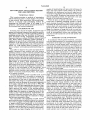
1
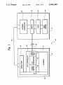
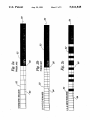
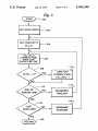
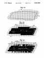
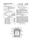
United States Patent‘ 1191
[11]
[45]
Gilbert et al.
METHOD FOR LASER PRINTERS
[57]
[76] Inventors: John M. Gilbert, 604 2nd St., NE,
Minneapolis, Minn. 55413; Lawrence
J. Lukis, 6366 150th St.; Leonard R.
Steidel, 3473 Willow Beach Trail
SW., both of Prior Lake, Minn.
U
' '
[58]
lutions in the horizontal and vertical dimensions is ac
complished by selectively modifying the on and off
states of pixels on either side of each vertical transition
point along the horizontal components of raster lines
representing the edges of the pixel representation of the
H04N 1/21
image. A processor is provided with an ideal outline of
""""""""""""""""""""
346/1 1_
the image and rasterizes the ideal outline of the image to
' """""""""""""""""""""" "
’ 358/2'96’
determine which pixels to turn on and which pixels to
Field of Search ............... .. 346/108, 107 R, 76 L,
“"11 Off in a frame buffer that Stores a Pixel representa
346/ 160, 11; 358/296, 300, 302, 298; 355/202
tion of the iamge to be printed by the laser printer. The
‘
References cued
U.S. PATENT DOCUMENTS
[56]
4,180,854 12/1979
4,682,189
ABSTRACT
be printed by a laser printer having unequal pixel reso
[21] Appl. N0.: 434,318
[22] Filed:
Nov. 13, 1989
[52]
Aug. 20, 1991
A non-gray scale anti-aliasing method for smoothing
the horizontal components of the edges of an image to
55372
Int Cl 5
5,041,848
Primary Examiner-Mark J. Reinhart
[54] NON-GARY SCALE ANTI-ALIASING
[51]
Patent Number:
Date of Patent:
modi?ed pixel representation in the frame buffer is then
communicated to the laser printer such that the laser
printer may print the smoothed image.
Walden et al. .................... .. 364/200
7/1987 Purdy et al. ...................... .. 364/900
11 Claims, 5 Drawing Sheets
22;
1
I
l
SEMI“ POR
A -/
T
1_x-e CONTROLUER
FRAME
co-
l
18
INTERNAL
CONTROLLER
N’ 20
SWlTCH
Ar'“
LASER
A. 124
me /30
VJTDEQ
JV‘
U
S
k 32
28/
k3‘
PC BOARD
as
L 36
A " 16
1
1
PRINT
, ENGINE
52
LX-6 NEW 600x300
.---—7—-—1
/1—‘
/
26
US. Patent
Aug. 20, 1991
OW
Sheet 2 of 5
5,041,848
Om
NM
NM
mm
. .ME.
mm
EHOE<Q
.MEem IPDE<A
Wm
WM
Wm
‘w
QOmI4xXO0Jw
_
a
US. Patent
Aug. 20, 1991
Sheet 3 of 5
Fig. 3a
PRIOR ART
—
Fig. 3b
Hg. 4a
PRIOR ART (4X)
Fig. 4b
5,041,848
US. Patent
Aug. 20, 1991
Sheet 4 of 5
5,041,848
Fig. 5
100
SET SCAN LINE-=0 a’ 102
SET PIXELCNT=O
FILL=O
it
C FILL=F|LL+
URRENT PIXEL
AREA THAT
“106
SHOULD BE "ON"
11p
TURN "ON"
CURRENT PIXEL
F|LL=FlLL-1
IS FILL >=1?
114
112
END OF
RASTE'R LINE’?
N0
INCREMENT
PIXELCNT
1@
LAST
NO
SCAN LINE?
INCREMENT -
SCANUNE
120' '
US. Patent
Aug. 20, 1991
Sheet 5 of 5
5,041,848
Fig. 6a
lll'l-l l‘nl'l
Hg. 60
62
61
F IHH
I
\l/
I
|
I
m?I
HIIHHIIH
I|
l
A
llll
lml
60
1
5,041,848
2
capable of implementing such gray-scale techniques. In
larger and more expensive laser printers, the problems
NON-GARY SCALE ANTI-ALIASING METHOD
FOR LASER PRINTERS
associated with aliasing and non-smooth edges may be
resolved by using higher pixel resolutions in these print
TECHNICAL FIELD
This invention pertains to methods of rasterization
and fill techniques used to create images to be printed
ers. In the smaller, inexpensive laser printers used with
desktop publishing systems, this approach is not used
by laser printers. More particularly, this invention per
While the prior art printer controller cards have al
because of the associated increase in cost.
tains to a non-gray scale anti-aliasing method for 10 lowed users of desktop publishing systems to signi?
cantly increase the quality of their printed outputs by
smoothing the horizontal edges of an image to be
increasing the horizontal resolution of the existing laser
printed by a laser printer having unequal resolutions in
printers used with such systems, it would be advanta
the horizontal and vertical dimensions.
geous to be able to improve the quality of the outline
BACKGROUND ART
edges of a character or image that occur in a near hori
zontal orientation, particularly if such an improvement
In recent years, the use of smaller, inexpensive laser
printers with personal computers has created an entirely -
could be accomplished without any additional hard
new industry referred to as desktop publishing. Desktop
publishing systems offer user the ability to format and
troller cards.
ware that would increase the cost of such printer con~
print documents having complicated layouts using
characters that have a variety of different fonts and type 20
sizes. While desktop publishing systems represent a
signi?cant advance in the art of publishing, the standard
resolution of the laser printers used with such systems
SUMMARY OF THE INVENTION
In accordance with the present invention, a non-gray
scale anti-aliasing method for smoothing the horizontal
components of the edges of an image to be printed by a
(typically a 300x300 dpi Canon CX or SX-based laser
laser printer having unequal pixel resolutions in the
printer, eg a HP LaserJet Series II printer) was too 25 horizontal and vertical dimensions is accomplished by
poor to compete with traditional phototypesetting sys
selectively modifying the on and off states of pixels on
tems.
either side of each vertical transition point along the
In an effort to improve the quality and speed of the
horizontal components of raster lines representing the
smaller, inexpensive laser printers used with desktop
edges of the pixel representation of the image. The
publishing systems, a variety of printer controller cards 30 method of the present invention may be used by a pro
have been introduced that may be installed either in the
laser printer or in the personal computer. Certain of the
printer controller cards that are installed directly in the
personal computer increase the quality and speed of the
cessor means that is provided with an ideal outline of
the image and rasterizes the ideal outline of the image
using the processor means to determine which pixels to
laser printers by using a separate co-processor and page 35 turn on and which pixels to turn off in a frame buffer
frame buffer to create a. pixel representation of the
image to be printed on the laser printer. This image is
then printed from the pixel representation in the page
frame buffer by directly controlling the modulation of
the laser in the print-engine of the laser printer. An
example of such a printer control card is the LX6 Pro
fessional printer controller cards available from Laser
Master Corporation, Eden Prairie, Minn., the assignee
of the present invention.
In some of the prior art printer controller cards, such
as the LX6 Professional, it is possible to increase the
memory means that stores a pixel representation of the
image to be printed by the laser printer. The method of
the present invention produces a modi?ed pixel repre
sentation in the frame buffer means that is communi
40 cated to the laser printer such that the laser printer may
print the smoothed image.
In essence, the present invention smooths each of the
vertical transition points between horizontal raster lines
by adding and subtracting pixels around this transition
point. The pixel representation created in the frame
the modulation of the laser in the print-engine of the
buffer for each horizontal raster line is used to control
the laser i the laser printer. When the laser is turned on
in response to an “on" pixel, a generally circular laser
laser printer. By doing so, the LX6 Professional printer
beam image is re?ected on the print drum of the print
of the pixel rrsolution of the laser printer to 600x300
dpi and 1000 X 400 dpi, depending upon the type of laser
printer. This increase in horizontal resolution signi?
charge elements attract and pick up the toner that is
then transferred to the sheet of paper. Although the
horizontal resolution of the laser printer by controlling
controller cards can increase the horizontal component 50 engine to transfer charge elements to the drum. The
cantly improves the quality of the resulting printed
image, particularly for pixel transition points along the
outline edges of a character or image that occur in the
vertical or near vertical orientation. Unfortunately, the
pixel elements are thought of as square or rectangular
shapes, in actuality, the edges of the pixels typically
55 bleed into one another to a signi?cant degree.
This is due to the laser power function at the surface
increased horizontal resolution does little to improve
the quality of the outline edges of a character or image
of the drum which typically decreases with the distance
from the center of the focal point over a generally cir
cular or elliptical area covering a space larger than the
that are near horizontal in slope.
theoretical rectangular pixel. Therefore the total laser
The noticeability and appearance of such vertical
pixel transition points is typically referred to as aliasing
that results in jagged or stairstep edges of the character
or image outline oriented generally in the horizontal
direction. Traditionally, anti-aliasing techniques incor
porating a gray-scale approach have been used in video
displays to resolve this type of problem. Unfortunately,
laser printers are binary imaging devices and are not
energy impinging upon a given point on the drum may
have components contributed by more than a single
sweep of the laser beam. This effect will be especially
pronounced in the region between the centerlines of
65 two adjacent raster lines. The total laser power imping
' ing on a given point determines the resulting amount of
charge on the drum at that point which in turn deter
mines whether toner will stick to that point or not.
3
5,041,848
4
printed by a laser printer having unequal resolutions in
It is believed that the present invention takes advan
tage of the physics of this process at the higher laser
the horizontal and vertical dimensions.
modulation rate generated by the printer controller
Another objective of the present invention is to in
crease the quality of the image printed using a printer
cards to create the desired smoothing of the transition
points. For edges in the near horizontal raster line just
below the outline edge, some of those charge elements
overlap onto the next horizontal raster line that contains
the outline edge with the transition point. In that next
horizontal line, the application of the laser in response
controller card without increasing the amount of frame
buffer memory required to store the pixel representa
tion of that image.
A further objective of the present invention is to
increase the quality of the image printed using a printer
to the modi?ed pixel representation briefly turns the a. . O controller card without requiring additional hardware
laser on, for example, for a selectively modi?ed “on"
circuitry on the printer controller card or the print
pixel prior to the transition point. The duration of this
pulse of laser energy is insuf?cient to charge this pixel
engine of the laser printer.
location enough to attract toner, however in the over
lap region, suf?cient charge may be added to the charge
already deposited by the lower raster linen to alter the
boundary of the region in which toner sticks to the
drum. Thus, in effect the location of a horizontal edge
of the image may be controlled to within less than the
width of a full pixel.
The most signi?cant advantage of using the smooth
ing method of the present invention in conjunction with
a laser printer having unequal resolutions in the hori
zontal and vertical dimensions is that quality of the
printed image is nearly equivalent to that of an image
printed on a much higher resolution printer having
equal resolutions in the horizontal and vertical dimen
sion. Although the resolution of the laser printer is
600x 300 dpi, the image produced using the method of
t. . 5
Still another objective of the present invention is to
implement the smoothing method of the present inven
tion during the ?ll process of theprasterization of the
pixel representation of the image without requiring any
post-rasterization processing or circuitry to accomplish
the smoothing of the images.
These and other objectives of the present invention
will become apparent with reference to the drawings,
the detailed description of the preferred embodiment
and the appended claims.
DESCRIPTION OF THE DRAWINGS
FIG. 1 is a block diagram of laser printing system
having a printer controller card for generating an image
to be printed by a laser printer having unequal resolu
tions in the horizontal and vertical dimensions.
FIGS. 20, 2b and 2c are schematic pixel representa
the present invention will more closely resemble 30 tions of a shallow horizontal outline edge for two prior
600x600 dpi print quality. An additional advantage is
art pixel representations and the modi?ed pixel repre
that this increase in quality is accomplished using the
sentation in accordance with the present invention.
modi?ed pixel representation in a frame buffer memory
FIGS. 30 and 3b are actual sample printouts of the
that occupies half of the space of the frame buffer mem
same ?lled polygon having a shallow horizontal edge
ory required to produce an equivalent pixel representa
using a prior laser printing system and a laser printing
tion for a higher resolution printer. As a result less
system incorporation the present invention.
memory is needed for the printer controller card and
FIGS. 4a and 4b are the same sample printouts as
the printer controller card is less expensive.
shown in FIGS. 30 and 312 shown in 4X scale.
In the preferred embodiment of the present invention,
FIG. 5 is a ?owchart showing the steps of the pre
the smoothing of the horizontal components of the 40 ferred embodiment of the smoothing method of the
edges of the ideal outline is accomplished during the fill
present invention.
process as each horizontal raster line is being rasterized.
FIGS. 6a, 6b and 6c are pixel representation of the
Typically, the horizontal raster lines are processed from
outline of a ?lled polygon showing the ideal outline
top to bottom in the frame buffer and the pixels are
alone, the ideal outline as ?lled using a prior laser print
processed from left to right. As each horizontal scan 45 ing system and the ideal outline as ?led using a laser
line of an ideal polygon outline is being rasterized, the
printing system incorporating the present invention.
processor accumulates a fill value that represents the
area of each pixel inside of the ideal outline that should
be turned “on” or ?lled. If the processor determines
that the area of the ?ll value is greater than the area of
a pixel, the pixel presently being processed is turned
“on“ and the area of a pixel is subtracted from the ?ll
value. In this embodiment, the ?ll value acts like a run
DESCRIPTION OF THE PREFERRED
EMBODIMENTS
Referring now to FIG. 1, a typical desktop publishing
system 10 having the printer controller card that exe
cutes the software that comprises the preferred embodi
ment of the present invention will be described. The
ning accumulator with the carry out of the accumulator
hardware for the desktop publishing system 10 is com
being used to determine whether the pixel presently 55 prised of a personal computer 12 connected with a
being processed should be turned “on”. Any number of
small, inexpensive laser printer 14. The personal com
methods can be used to determine the amount of the ?ll
value for each pixel. For example, instead of calculating
puter 12 may be any one of a variety of personal com
puters such as an IBM PC, XT/AT, 386, or PS/Z, avail
the entire area inside the ideal outline, the height of the
able from International Business Machines, Armonk,
midpoint of the segment of the ideal outline in the pixel 60 N.Y., or an Apple Macintosh, available from Apple
or the height of the intersection of the ideal outline with
Computers, Inc. Cupertino, Calif. The personal com
the right or left edge of the pixel could be used to esti
puter 12 may be provided with a desktop publishing
mate the value of the area inside the ideal outline. A
software package, such as Ventura Publisher, available
similar method may be used to process edges and transi
from Xerox Corporation, PageMaker, available from
tions which occur in the near vertical direction.
Aldus Corporation, or GEM Desktop Publisher, avail
A primary objective of the present invention is to
able from Digital Research, Inc. The laser printer 14
provide a non-gray scale anti-aliasing method for
smpothing the horizontal edges of an image to be
may be any type of Canon CX or SX laser printer such
as the HP LaserJet Series II available from Hewlett
5
5,041,848
6
24 via a video cable 38. An internal switch 40 in the
laser printer 14 allows the printer controller 30 to over
Packard, the LaserWriter, available from Apple Com
puter, Inc., or the Canon LBPS-III, available from
Canon.
ride the internal controller 20 of the laser printer and
directly modulate the laser 24. It is this direct modula
tion of the laser 24 that allows the printer controller 30
to increase the horizontal resolution of the laser printer
14. For a more detailed explanation of the operation the
LX6 printer controller 30, reference is made to the LX
In normal operation without a printer controller
card, the personal computer 12 includes a main PC
mother board 16 and a serial port 18 through which the
personal computer 12 communicates with the internal
controller 20 of the laser printer 14. The computer 12
sends a serial bit stream to the laser printer 14 over an
RS-232-C serial interface 22 in the form of various com
User Guide, which is incorporated herein by reference
mands and data that represent the image to be printed
by the laser printer 14. The internal controller 20 de
codes the serial bit stream and generates the control
signals that will be supplied to the laser 24 to drive the
Referring now to FIGS. Za-ec, the differences be
tween the smoothing method of the present invention
and the prior art will be described. Each of FIGS. 20-20
show a single raster horizontal raster line 50 comprised
of a plurality of pixels 52 that may either be white
(“ofl") or black (“on”). Also shown is the ideal line 54
and is available from LaserMaster Corporation.
print engine 26 that creates the printed images corre
sponding to the various commands and data received by
that forms the outline of the image or character to be
printed. In this case, the ideal line 54 is the worst case
the internal controller. For a more detailed explanation
of the internal operation of the laser printer 14, refer
version of a shallow horizontal line for the edge of an
ence is made to the LaserJet II Printer User’s Manual,
Edition 1, available from Hewlett-Packard.
20
outline. The prior art is represented by the 300>< 300 dpi
Because of the inherent limitations on the speed at
raster line 50 generated by the internal controller 20 as
which the commands and data can be transferred over
shown in FIGS. 2al , and the 600x 300 dpi raster line 50
the serial interface and decoded by the internal control
generated by the LX6 controller 30 without using the
method of the present invention. It can easily be seen
that there is a very de?nite and sharp vertical transition
ler 20, the page throughput for the laser printer 14 is
typically very low, 6 pages per minute or less, depend
ing upon the formatting and type of information being
printed. To solve this problem and to simultaneously
increase the quality and performance features of the
laser printer, various printer controller cards 30 have
been introduced into desktop publishing systems, such
as the LX6 Professional, available from LaserMaster
point 56 at the edges of the two pixels adjacent the point
where the ideal line 54 crosses the midway vertical
height of the pixels 52. This de?ne and sharp vertical
transition point 56 creates jagged edges or “steps” that
are visible to the human eye as shown for example in
FIGS. 30 and 4a. In contrast, the raster line 50 shown in
Corporation, Eden Prairie, Minn. The printer control
FIG. 2c that is generated by the LX6 controller 30 using
ler card 30 of the preferred embodiment is located in the
the method of the present invention does not have such
personal computer 12 and communicates directly with
a sharp black-and-white vertical transition point 56. By
selectively turning on pixels in the raster line 50 to the
the PC mother board 16 via an internal bus 28. It will be
recognized, however, that the printer controller board
30 may be located in the laser printer 14 or that the
present invention may be implemented within the inter
nal controller 20 of the laser printer 14.
left of the transition point 56 and turning off pixels to
the right of the transition point 56, the present invention
smooths the transition point 56 as seen by the human
eye as shown for example in FIG. 3b and 4b. Vertical
In the preferred embodiment, the printer controller
40 and near vertical edges are smoothed in much the same
card 30 is an LX6 Professional printer controller card
fashion. It will be understood that the smoothing of
transitions may also be effective when operating at
selected to match the particular type of laser printer 14
being used in the desktop publishing system 10. The
equal resolutions, although the preferred embodiment
of the present invention is most successful with unequal
LX6 controller consists of a frame buffer 32, a co
processor 34 and a video interface 36. The co-processor 45 horizontal and vertical dimensions.
34 receives the various commands and data represent
ing the image to be printed from the PC mother board
16 via the bus 28. Because the bus 28 is a parallel bus, the
transfer rate is much faster than for the serial port 18.
The co-processor 34 decodes the commands and infor
mation and produces a mathematically pure ideal out
line corresponding to a ?lled polygon that will repre
sent each image or character to be printed. The 00
processor 34 may also aid the personal computer 12 in a
rendering lines, graphics and characters as determined
In the preferred embodiment, the smoothing method
of the present invention is applied by the co-processor
34 as it is generating each horizontal raster line 50 to be
stored in the frame buffer 32. Typically, the horizontal
raster lines 50 are processed from top to bottom in the
frame buffer 32 and the pixels 52 are processed from left
to right, although it will be recognized that the raster
lines 50 and pixels 52 may be processed in any direction
so long as the processing is consistent throughout an
entire page in the frame buffer 32. As the decision is
by the particular application software package cur
made whether to turn a pixel 52 on or off, a ?ll value
rently being run on the personal computer 12.
Once the ideal outline is generated, it is then ?lled in
or “rasterized” to produce a pixel representation of the
image to be printed that is stored in the memory of the
frame buffer 32. Any number of known ?ll techniques
or algorithms may be used to ?ll in the pixels inside of
representing the area between edge of the ideal outline
54 and the edge of the pixel 52 is accumulated. When
the outline, depending upon how overlapping images
are to be handled. When the laser printer 14 is ready to
print a page or “frame” worth of images, the pixel rep
resentation in the frame buffer 34 is transferred to the
laser printer 14 via the video interface 36 in the printer
controller 30 that communicates directly with the laser
the ?ll value is equal to or greater than the total area of
a single pixel, the pixel presently being operated on is
turned “on" and the area of a single pixel is subtracted
from the ?ll value. In this embodiment, the ?ll value
acts like a running accumulator with the carry out of
the accumulator being used to determine whether the
pixel presently being processed should be turned “on”.
Any number of methods can be used to determine the
amount of the ?ll value for each pixel. For example,
instead of calculating the entire area inside the ideal
7
5,041,848
outline, the height of the midpoint of the segment of the
ideal outline in the pixel or the height of the intersection
8
inside the ideal outline 54 (below the line segment 60) is
l/20th the area of an entire pixel 52. For pixel 62, the
area is 2/20th, etc. By accumulating the values for each
of the ideal outline with the right or left edge of the
pixel could be used to estimate the value of the area
of the pixels in line segment 60, it can be seen that at
inside the ideal outline. Similar algorithms may be used
pixel
66,
the
value
of
FILL=2l/2O
(l/20+2/20+3/20+4/20+5/20+6/20).
Conse
to process short vector and curves in order to apply the
smoothing method of the present invention to a variety
quently, pixel 66 is turned on and FILL now equals
l/20. The process is continued and at pixel 69, FILL is
of different shapes.
Referring now to FIGS. 5 and 6, the operation of the
again greater than or equal to 1 and FILL=25/2O
preferred method of the present invention will be de
scribed in greater detail. At Start 100, an ideal outline 54
(l/20+7/20+8/20+9/20).
as shown in FIG. 60 has been determined based upon
the outline of the image or character to be printed. It
invention is described with respect to the ?lling or rast
should be noted that, in general, the characters or im
ages to be printed can be thought of as ?lled polygons,
or combinations of ?lled polygons. It is also possible to
as well as to any ?lled polygon where it is desired to
use the method of the present invention with ideal out
lines 54 whose edges are in the form of arcs and curves,
Although the preferred embodiment of the present
erizing of an ideal outline, it should be noted that the
method of the present invention may be applied equally
- smooth the horizontal components of the polygon when
printing the image out on a printer having unequal hori
zontal and vertical resolutions. In this situation, the
rather than straight lines. At 102, the value SCAN
ideal outline could be assumed to be a series of lines
LINE representing the number of horizontal scan lines 20 segments constructed around the outermost edges of
50 in the frame buffer 32 is set equal to zero. At 104, the
value PIXELCNT representing the number of pixels 52
the horizontal components of the ?lled polygon.
Although the description of the preferred embodi~
in a scan line 50 and the value FILL representing the
ment has been presented, it is contemplated that various
area of a single pixel 52 are also set to zero. In this
changes
could be made without deviating from the
embodiment, the area of a single pixel 52 is assumed to 25
be one for simplicity of explanation. It will be under
stood that the value of FILL may be determined using
any of the methods discussed above for estimating the
area of the pixel 52 inside the ideal outline 54.
At this point, the software program that is imple
menting the method of the present invention on the
co-processor 34 of the controller card 30 is ready to
spirit of the present invention. Accordingly, it is in
tended that the scope of the present invention be dic
tated by the appended claims rather'than by the descrip
tion of the preferred embodiment.
We claim:
1. A method for smoothing the edges of an image to
be printed by a binary imaging printer having unequal
start rasterizing the ideal outline 54 to produce the hori
pixel resolutions in the horizontal and vertical dimen
should be “on” because it is inside the ideal ‘outlet 54 is
added to FILL. At 108, the value of FILL is compared
the image;
rasterizing the ideal outline of the image using the
to see if the current pixel should be turned on. If so, at
processor means to determine which pixels to turn
on and which pixels to turn off in a frame buffer
memory means that stores a pixel representation of
sions, comprising the steps of:
zontal raster lines 50 that will be stored in the frame
providing a processor means with an ideal outline of
buffer 32. At 106, the value of the current pixel area that 35
110, the current pixel is turned on and the value of the
area of a single pixel (1) is subtracted from FILL. At
112, a check on PIXELCNT to see if processing is at
the end of a raster line 54. If not, then PIXELCNT is
incremented and the loop is reentered at 106. If it is the
end of a raster line, then a check on SCANLINE is
made at 116 to see if this is the last raster line in the 45
frame buffer 32. If not, the SCANLINE is incremented
at 118 and the loop is reentered at 104. When the frame
the image to be printed by the printer;
smoothing the edges of the digital outline by selec
tively modifying the on and off states of pixels on
either side of each vertical transition point along
the horizontal components of the edges of the pixel
representation of the image to produce a modi?ed
pixel representation in the frame buffer means; and
communicating the modi?ed pixel representation
buffer 32 has been completely rasterized, then control is
stored in the frame buffer memory means to the
returned from the software program via RETURN 120.
printer such that the printer may print the
To understand how the preferred embodiment of the 50
smoothed image.
present invention would work in practice and how it
2. A method of smoothing the horizontal components
compares with the prior art, reference is made ‘0 FIGS.
of the edges of an ideal outline of an image to be printed
6b and 6c. It will be noted that the pixels 52 in these
by a binary imaging printer having unequal pixel resolu
?gures are rectangular indicating the non-uniform hori
zontal and vertical resolutions of the printer used to 55 tions in the horizontal and vertical dimensions, compris
ing the steps of:
print these images. Using the line segment 60 as an
rasterizing the ideal outline of the image using a pro
example, it will be seen that the line segment 60 is one
cessor means to process a plurality of horizontal
pixel high and 20 pixels long. In this case, the transition
raster lines comprised of a plurality of pixels, each
point 56 using the prior art rasterization methods is 10
pixels in from ether end of the line segment 60. All of 60
pixel having a given total area, to form a pixel
the pixels to the left of transition point 56 are “off’ and
representation of the image in a frame buffer, the
all of the pixels to the right of transition point 56 are
rasterizing being performed to smooth the horizon
“on”. In contrast, in FIG. 6c, the pixels 52 along the line
tal components of the ideal outline of the image by
segment 60 are selectively turned off and on around the
performing the following steps for each of the
transition point 56. For purposes of estimating the area 65
horizontal raster lines;
of each pixel 52 to be turned on, an assumption is made
accumulating a ?ll value representing the area in
that the increase in area for each pixel is represented by
side the ideal outline for the pixel currently being
the slope of the line: l/20. Hence, for pixel 61, the area
processed;
9
5,041,848
area; and
area; and
if the ?ll value is greater than the total area, turning
if the ?ll value is greater than the total area, turning
on the pixel currently being processed and sub
on the pixel currently being processed and sub
tracting the total area from the ?ll value.
8. The method of claim 2 wherein the step of accumu
lating a ?ll value representing the area inside the ideal
tracting the total area from the ?ll value.
3. The method of claim 1 wherein the processor
means is comprised of a printer control card operably
connected with a computer, the printer control card
including a co-processor for rasterizing the ideal outline
of the image, the frame buffer memory means for stor
ing the pixel representation of the image to be printed
by the printer, and a video interface for communicating
the modi?ed pixel representation stored in the frame
buffer means to the printer.
4. The method of claim 3 wherein the ideal outline is
generated by the co-processor in response to commands
and data received from the computer.
10
determining if the ?ll value is greater that the total
determining if the ?ll value is greater than the total
outline for the pixel currently being processed is accom
plished by calculating the entire area inside the ideal
outline.
_
9. The method of claim 2 wherein the step of accumu
lating a ?ll value representing the area inside the ideal
15
outline for the pixel currently being processed is accom
plished by estimating the area inside the ideal outline
based upon the height of the midpoint of a segment of
the ideal outline that crosses the pixel currently being
processed.
10. The method of claim 2 wherein the step of accu
mulating a ?ll value representing the area inside the
5. The method of claim 1 wherein the binary imaging 20 ideal outline for the pixel currently being processed is
accomplished by estimating the area inside the ideal
printer is a laser printer including a laser and a marking
outline based upon the height of the left height of the
engine.
left edge of a segment of the ideal outline that crosses
6. The method of claim 5 wherein the step of commu
the pixel currently being processed.
nicating the modi?ed pixel representation to the printer
is accomplished by using a video interface to directly
modulate the laser in the laser printer.
11. The method of claim 2 wherein the step of accu
mulating a ?ll value representing thearea inside the
ideal outline for the pixel currently being processed is
7. The method of claim 1 wherein the step of smooth
accomplished by estimating the area inside the ideal
outline based upon the height of the right edge of a
segment of the ideal outline that crosses the pixel cur
ing the edges of the digital outlines is accomplished by:
accumulating a ?ll value representing the area inside
rently being processed.
the ideal outline for the pixel currently being pro
t
cessed;
35
45
55
65
t
i
i
i