1
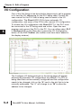
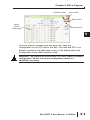
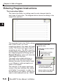
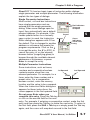
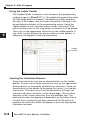
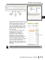
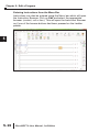
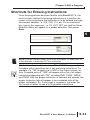
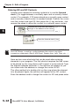
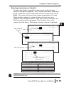
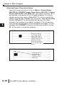
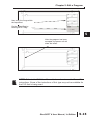
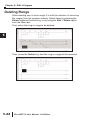
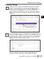
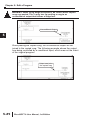
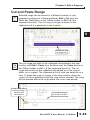
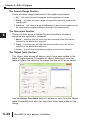
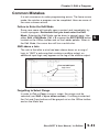
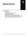
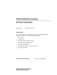
EDIT A PROGRAM
CHAPTER
5
In This Chapter
I/O Configuration . . . . . . . . . . . . . . . . . . . . . . . . . . . . . .5-2
Referencing Program Elements . . . . . . . . . . . . . . . . . .5-4
Entering Program Instructions . . . . . . . . . . . . . . . . . . . .5-6
Shortcuts for Entering Instructions . . . . . . . . . . . . . . .5-11
Drawing/Deleting Connecting Lines . . . . . . . . . . . . . .5-19
Selecting Rungs for Deleting, Cutting or Copying . . .5-21
Deleting Rungs . . . . . . . . . . . . . . . . . . . . . . . . . . . . . .5-22
Copying Rungs . . . . . . . . . . . . . . . . . . . . . . . . . . . . . .5-23
Cut and Paste Rungs . . . . . . . . . . . . . . . . . . . . . . . . .5-25
Merge (Combine) Rungs . . . . . . . . . . . . . . . . . . . . . . .5-26
Inserting Columns, Rows and Rungs . . . . . . . . . . . . .5-27
Using Search and Replace . . . . . . . . . . . . . . . . . . . . .5-29
Common Mistakes . . . . . . . . . . . . . . . . . . . . . . . . . . . .5-31
Chapter 5: Edit a Program
I/O Configuration
1
2
3
D
5
6
7
8
9
1
11
2
13
4
A
B
C
D
5-2
One of the first things to be done before beginning to edit a program
is to view the I/O addressing for the PLC being used. Consult the
user manual for the PLC that is being used to assist in the I/O
configuration. The DirectLOGIC PLCs have automatic I/O
configuration, and some of the CPUs offer manual I/O configuration.
To access the I/O configuration with DirectSOFT 6, the PLC must
be connected to the PC being used and online. Open the new
program and connect the PLC to the PC. You can either select PLC
> Configure I/O on the Menu bar or press the I/O Configuration
button on the PLC Toolbar (the toolbar must have been added to
the display window).
The Configure I/O dialog pictured on the facing page will appear
showing the automatic I/O configuration (by default). If a CPU is
being used that can be manually configured and the configuration
needs to be changed, click on the “A” next to the slot that is to be
manually addressed. The “A” will change to an “M” to allow the
address to be changed.
DirectSOFT 6 User Manual, 1st Edition
Chapter 5: Edit a Program
Read from disk
Save to disk
Save to PLC
Select
manual
configuration
Read from PLC
After the manual configuration has been set, save the
configuration to the PLC and to the disk. The disk and PLC icon
buttons located in the right-hand corner of the dialog allows the
configuration to be either saved or read.
WARNING: The majority of DirectLOGIC PLCs only require automatic
configuration. Do not use manual configuration unless it is
absolutely necessary.
DirectSOFT 6 User Manual, 1st Edition
1
2
3
D
5
6
7
8
9
0
1
2
3
4
A
B
C
D
5-3
Chapter 5: Edit a Program
Referencing Program Elements
Data Types
2
3
5
6
7
8
9
1
11
2
13
4
A
B
C
D
5-4
It’s good to know the various ways to refer to the different types of
elements in the PLC. If you have used the DirectLOGIC compatible
products, such as the TI305 , TI405 , or SIMATIC® TI versions, you
are probably familiar with the way elements are represented. The
following table provides a complete list of the various data types and
their meanings.
TM
Type of Data
TM
DL305C
DL05/DL06/DL105
(DL330/DL340 CPU) DL205/DL350/DL405
Input Points
IO
Output Points
IO
Control Relays
C
Stages
S
Timers
T
Timer current
TCA
Counters
CT
Counters current
TCA
Remote I/O Points
IO
Data Registers
R
Pointers (to another V location)
N/A
Special Relays
Uses special C locations
Input Points as Registers
RIO
Output Points as Registers
RIO
Control Relays as Registers
RC
Timer Status Bits as Registers
N/A
Counter Status Bits as Registers
N/A
Remote I/O as Registers
RIO
Special Relays as Registers
RIO
Timer current Values as Pointers
N/A
(to another V location)
Counter current Values as
Pointers (to another V location)
Constants
Octal Constants
Bit of Word
Pointer to Bit of Word
N/A
K
N/A
N/A
N/A
DirectSOFT 6 User Manual, 1st Edition
X
Y
C
S
T
TA
CT
CTA
GX/GY
V
P
SP
VX
VY
VC
VT
VCT
VGX/VGY
VSP
PTA
PCTA
K
O
B
PB
Chapter 5: Edit a Program
Aliases
Chapter 4 briefly mentioned the use of aliases to make some data
references easier to understand. By default, they are displayed
when you type their counterpart. If it is desired not to have the
aliases shown when editing a program, they can be turned off in
the Global dialog in the Options menu. Below are examples which
show how aliases are used.
NOTE: These references are only used within DirectSOFT. They cannot
be used with the Handheld Programmers. The actual instructions
contained in the CPU will reflect the actual data type, not the new
reference.
Timer/Counter Current Values
The DL05, DL06, DL105, DL205, DL350 and
DL405 CPUs use designated V-memory
locations to hold timer and counter current
values. The current value for Timer T0 is stored
in V0. This is not always easy to remember, so
DirectSOFT 6 allows you to refer to these as
either V0 or TA0 (timer accumulated value for
Timer 0). For example, the accumulator for
Counter 3 is in CTA3 which is easier to
remember than V1003.
Use Timer Accumulator
Reference
TA0
K100
OR
Use V-memory Location
V0
K100
Accessing I/O Points as Memory Locations
1
2
3
D
5
6
7
8
9
0
1
2
3
4
A
B
C
D
Aliases allow you to access I/O points as VUse VX reference to I/O
memory (registers in a DL305C). For example,
LD
input points X0 - X17 in a DL405 are stored in
VX20
V40400, X20 - X37 are stored in V40401, etc.
VX0 (the alias) can be used instead of V40400,
the V-memory location for X0. These are on 16- OR
point boundaries, so the next location is VX20, Use V-memory Location
VX40, VX60, etc. For the DL305C, you could
LD
represent I/O points such as IO10 - IO17 with
V40401
register location RIO10.
For example, you may want to read in a range
of discrete input points to get a binary pattern into the CPU
accumulator. The diagram shows two ways to reference the location.
NOTE: Check the appropriate PLC user manual for a description of the
accumulator and instructions required for this type of task.
DirectSOFT 6 User Manual, 1st Edition
5-5
Chapter 5: Edit a Program
Entering Program Instructions
The Instruction Editor
2
3
5
6
7
8
9
1
11
2
13
4
A
B
C
D
5-6
The Instruction Editor is a dialog used to enter element data for
each type of instruction. The diagram below shows the dialog in the
output entry position.
The expanded Instruction Editor dialog
has a check mark, an X and
magnifying glass in the upper left-hand
corner. The check mark (冑冑) is used for
accepting an entry. The (X) is used for
closing without accepting an entry. And
the magnifying glass will bring up the
Element Browser, which will show the
valid ranges for this field.
The small color-coded indicators in
each field of the input box indicate
whether the entry for that field is valid
or not. Green is valid and red is not
valid or incomplete.
The indicator in the upper right-hand
corner of the box indicates the validity
of all fields. For example, in order for
the indicator to turn green, the box will
need a valid address such as, V2000.
DirectSOFT 6 User Manual, 1st Edition
Click here to close and
accept the entry
Click here to close without
accepting
Click here to see the
element browser
(or press F9)
Valid entry indicator
for the immediate field
Master valid entry indicator
for the entire instruction
Chapter 5: Edit a Program
DirectSOFT 6 has two basic types of instruction editor dialogs:
single parameter and multiple parameter. The following information
explain the two types of dialogs.
Single Parameter Instructions
Most contact, coil and box instructions
have single parameters and are
entered with the single parameter
dialog. When some dialogs open for
input, they automatically use a default
element address. For example, if the
Cancel
Ladder palette button for a normally
open contact is used, the Instruction Accept
Editor dialog box appears with C0 as
the default. This is changed to another
address or nickname that meets the
program requirements. Click on the 冑
to accept the entry, the X (or ESC) to
cancel the entry, or on the element
browser button (magnifying glass) to
browse through the available element
addresses or nicknames, or press
Enter to accept the entry.
Red indicators
show not
complete
Green
Indicators
show valid
entry
1
2
3
D
5
6
7
8
9
0
1
2
3
4
A
B
C
D
Multiple Parameter Instructions
Some instructions, such as timers,
counters and comparative boolean
1st Operand
2nd Operand
contacts require more than one
element parameter. For example, for a
CTA0 K5
timer, enter the timer number and a
preset value. For a comparative
boolean contact, enter the memory
location and the value to be compared.
When the Instruction Editor dialog box
appears for these instructions, the
cursor appears in the first operand field.
Do not press Enter when you
complete this entry. Press the Tab key
or click on the second field for the next
entry. For example, if entering a comparative contact, make the first
entry and then press the Tab key to make the next entry. To return to
the first field, press the Shift + Tab keys or simply press the Tab key
again, and the cursor will wrap back around to the first field.
DirectSOFT 6 User Manual, 1st Edition
5-7
Chapter 5: Edit a Program
Using the Ladder Palette
2
3
5
6
7
8
9
1
11
2
13
4
A
B
C
D
5-8
The Ladder Palette is always in view whenever the programming
window is open in DirectSOFT 6. The palette becomes active when
the Edit Mode button is pressed. The palette is initially docked to
the right of the Ladder view, but when the palette is floating, it can
be positioned anywhere on the programming screen. Using the
Ladder palette is one of several ways to enter instructions. First,
place the edit cursor on the rung where an element is to be placed.
Then click on the appropriate instruction on the Ladder palette. If
one of the contact buttons (the top ten buttons on the palette), a
dialog box will appear to enter the parameters.
Ladder
Palette
Opening the Instruction Browser
Some instructions do not have an element button on the Ladder
palette. To enter one of these instructions, click on the appropriate
browser button on the palette and select an instruction. There are
three buttons on the palette for browsing the contact, coil and box
instructions. Clicking on any of the browse buttons will open the
Instruction Browser, as shown on the facing page. This will allow
selection of the correct instruction from the available lists. The
particular browser that appears is dependent on the button that is
clicked. Once a selection has been made and the OK button is
pressed, the Instruction Editor will appear to have the appropriate
information entered.
DirectSOFT 6 User Manual, 1st Edition
Chapter 5: Edit a Program
1
Browse
Contacts
(F4)
Browse
Coils
(F5)
Browse
Boxes
(F7)
Entering Instructions with Hot Keys
When the cursor is moved to one
of the Ladder palette buttons, a
Tool Tip will appear. The Tool Tips
provide a brief description of the
button and the associated hot key
for that button.
You can enter an instruction by
pressing the hot key which
corresponds to the type of
instruction to be entered. For
example, to enter a normally
opened input, press F2. After the
hot key has been pressed, the
Instruction Editor dialog will appear.
For the browse buttons, the
particular Instruction Browser will
appear so the proper selection can
be made.
NOTE: A complete list of the hot keys is available from the Help menu.
DirectSOFT 6 User Manual, 1st Edition
2
3
D
5
6
7
8
9
0
1
2
3
4
A
B
C
D
5-9
Chapter 5: Edit a Program
2
3
Entering Instructions from the Menu Bar
Instructions can also be entered using the Menu bar which will open
the Instruction Browser. Click on Edit and select the appropriate
browser (contact, coil or box). This will open the Instruction Browser
as if one of the browse buttons had been pressed on the Ladder
palette.
5
6
7
8
9
1
11
2
13
4
A
B
C
D
5-10
DirectSOFT 6 User Manual, 1st Edition
Chapter 5: Edit a Program
Shortcuts for Entering Instructions
Once the programmer becomes familiar with DirectSOFT 6, the
most common method for entering instructions is to position the
cursor on the rung where the instruction is to be entered and type
the element address, i.e. X12, C22, Y14, etc. For an instruction
box, type in the mnemonic, i.e. LD, OUT, SET, etc. and the Token
Selection Editor will appear for a proper selection. Then press
Enter.
NOTE: Use the Ladder Palette, the hot key equivalent, or select the Coil
or Box Browser to enter the OUT box instruction.
TIP: The Token Selection Editor feature in DirectSOFT 6 supports Auto
Complete with a drop-down list of any matching instructions. For
example, if a “TM” is typed over a NOP in the output column, an
Auto Complete entry of “TMR” will appear with a list of all output
instructions beginning with “TM”, including TMR, TMRA, TMRAF
and TMRF. After the proper instruction is selected and entered, the
proper Instruction box will appear to be completed with all the
proper information. So, if you forget a mnemonic, just enter the
first couple of letters to see a list of possible instructions.
DirectSOFT 6 User Manual, 1st Edition
1
2
3
D
5
6
7
8
9
0
1
2
3
4
A
B
C
D
5-11
Chapter 5: Edit a Program
Entering NO and NC Contacts
2
3
5
6
7
8
9
1
11
2
13
4
A
B
C
D
5-12
Another quick method for entering contacts is to use the forward
slash (/) to toggle between a normally open and a normally closed
contact. For example, if X0 was entered as a normally open contact
and a normally closed contact is needed instead. Position the cursor
over the contact and type X0, then press the (/) key and enter. Just
reverse the steps to return the contact to a normally open contact.
Position the cursor over the contact
and type in the address of the contact
Press the forward slash (/) key
NOTE: The forward slash can also be used to switch between OUT Coils
and OUT Boxes, as well as cycling between the various rung inline
comparison statements (Equal, Not Equal, Greater than, Less Than, etc…)
Here are two more shortcuts that can be used when entering
elements in your program. The first shortcut requires the Edit cursor
to be placed on the rung where a NO contact is to be entered. Type
the element address and enter it. The edit box will appear so you
can either enter the address or change the contact to NC.
The other method is to double-click on the rung where the element
is to be placed. Again, the edit box will appear with a NO contact.
Enter the address and/or change the contact to NC and press enter.
DirectSOFT 6 User Manual, 1st Edition
Entering Instructions in Parallel
Chapter 5: Edit a Program
To enter instructions in parallel, make normal contact entries
similar to the below diagrams. Two contacts have been entered on
Rung 2. With the cursor located after the last contact entry, press
Enter. The cursor will move down a space equivalent to a rung.
Make another contact or contact entries, such as two more
contacts in the illustation below. Once this is done, hold down the
Ctrl key and press the up arrow. This will draw a line up to
connect the line above. Editing the rung can now be completed.
Edit a new line
and enter
Edit more contacts
Use Ctrl + up arrow to
draw a line up
Draw Rung Lines
Key Stroke
Ctrl +Up Arrow
Ctrl +Down Arrow
Ctrl +Left Arrow
Ctrl +Right Arrow
Function
Draw a vertical line up
Draw a vertical line down
Draw a horizontal line left
Draw a horizontal line right
1
2
3
D
5
6
7
8
9
0
1
2
3
4
A
B
C
D
NOTE: To delete lines, press and hold Shift + Ctrl, then press the
appropriate arrow key.
DirectSOFT 6 User Manual, 1st Edition
5-13
Chapter 5: Edit a Program
Entering Power Flow Instructions
2
3
5
6
7
8
9
1
11
2
13
4
A
B
C
D
5-14
There are some instructions, such as Master Control Relays
(MLR/MLS), FOR/NEXT loops, Stage Boxes (SG, ISG), Program
Control (GOTO/LBL, INT, SBR), etc., that offset the power rail or
are inserted in the power rail of the ladder program. A common
mistake among new users of DirectSOFT 6 is to try and edit the
offsets using the Ctrl + Arrow (line connector). This will not work.
Actually, DirectSOFT 6 will automatically perform the offset
whenever the program is accepted (compiled). This will become
clear through the examples on the immediate two pages. For this
example, the FOR/NEXT instruction will be used and the hot key,
F8, will be used to accept the program.
Begin by entering
the first part of the
loop 앥 the FOR
instruction. Use the
special relay SP1 to
activate the loop.
Enter the parameter
K8 to run the loop 8
times.
Press the F8 key
to accept the
program. Notice
the offset of the
power rail.
DirectSOFT 6 User Manual, 1st Edition
Chapter 5: Edit a Program
1
Now, enter the rungs within
the loop offset.
2
3
D
5
6
7
8
9
0
1
2
3
4
NOTE: Refer to the PLC User Manual to learn how to use the Power Flow A
instructions. Some of the instructions of this type may not be available for
the PLC that is being used.
B
C
D
End the offset loop by
entering NEXT rung.
After the program has been
accepted, the power rail will
show the offset.
DirectSOFT 6 User Manual, 1st Edition
5-15
Chapter 5: Edit a Program
Entering Special Case Elements
2
3
5
6
7
8
9
1
11
2
13
4
A
B
C
D
5-16
Some elements are special because they do not follow the usual
rules (i.e. 330S Timers/Counters, DL330/DL340 CT674-CT677) or
they are entered in, perhaps, different ways than one might expect.
This will be discussed on this page and the following page.
If you have a DL330, DL340 or compatible PLC, then you know the
counters/timers CT674 through CT677 cannot take software presets
in the same manner as all its other built-in counters/timers. These
counters/timers are designed to have their presets entered via an
external hardware device (D3-TCSU Timer/Counter Setpoint Unit).
Preset values cannot be entered for CT674-CT677 via the
timer/counter entry dialog.
This presents a unique situation for DirectSOFT 6 because for
these two CPUs, DirectSOFT 6 will always show two input fields
timer/counter address and preset) for all of its timers/counters and
makes no exception for these special cases. The element can be
entered in the ladder logic, but the second field is ignored in the
editor dialog. The edit dialog will not allow a preset to be
entered. This Second field is intended for presets on all other
timers/counters, and not these being discussed. Once the address
has been entered in the aforementioned timers/counters, just press
enter to close the box. The preset entry will be made via the D3TCSU thumbwheels, and the preset can only be viewed on the
Setpoint Unit.
A preset cannot be entered for DL330/DL340
Timers/Counters CT674-CT677. Leave the
preset field blank.
DirectSOFT 6 User Manual, 1st Edition
Chapter 5: Edit a Program
TI330S/TI325S and DL330P Exceptions
If you have a TI330S/TI325S or DL330P, then the situation will be
slightly different from the one explained on the previous page.
These CPUs do not allow presets for any of their counters/timers
via the edit dialog of DirectSOFT 6. It is sometimes confusing to
users of previous versions DirectSOFT with other PLCs because
of the preset entry. The preset for the counters/timers being
discussed do not need a preset entry in the edit dialog. The only
entry to be made in the edit dialog is the counter/timer address.
Refer to the PLC User Manual for a detailed discussion of how
these timers work with their presets.
End Coil
The TI330S/TI325S/DL330P counters/timers
do not have a preset field.
All of the instruction sets in DirectLOGIC PLCs and compatibles,
use an END coil as one of the instructions. This may be a bit
different for new users of DirectLOGIC PLCs. The END coil is a
marker to designate the end of a program. Every DirectSOFT 6
program must have this instruction.
Like all coils, the END coil is found in the Coil Instruction Browser.
Some programmers get confused at first and look for the END coil
under the Standard Coil category, and they fail to find it. The END
coil is located under the Program Control category since it ends
the program.
The END coil is found under
Program Control and not
under the Standard Coil
category.
DirectSOFT 6 User Manual, 1st Edition
1
2
3
D
5
6
7
8
9
0
1
2
3
4
A
B
C
D
5-17
Chapter 5: Edit a Program
Setting and Resetting a Bit
Several PLCs in the DirectLOGIC family have a feature that allows
setting and resetting individual bits. This is commonly called “Bit-ofWord”. The PLCs which support this feature include the DL05,
DL06, DL250-1, DL260 and DL450. The DirectSOFT 6 instructions
available for these PLCs offering Bit-of-Word include all of the STR,
AND, OR and OUT instructions and all SET and RST instructions.
Notice SET and RST examples shown below, the letter ‘b’ precedes
the memory location where the bit is to be manipulated in some
way. After the V-memory address of the word, use a decimal point
and a number between 0 and 15 (zero being the least significant bit)
to designate which bit is to be set. For example, b1400.3 is the
fourth bit of V1400.
2
3
5
6
7
8
9
1
11
2
13
4
A
B
C
D
Enter the letter ‘b’
followed by the memory
address of the word
containing the bit to be
turned ON. Use a
decimal point plus a
value between 0 and 15
to designate which bit to
turn ON, i.e. B1400.3 is
the fourth bit of V1400.
Ignore the second field.
....And, to reset the bit....
Use the same decimal
point convention with the
RST instruction.
The same convention is
used for the STR, AND,
OR and OUT instructions
(not shown).
NOTE: The letter “b” can be entered in either lower case or upper case.
The end result will be an upper case “B” appearing in the program.
Using Floating Point Math
5-18
Small, low-end PLCs typically allow the use of integers, but do not
allow the use of math containing decimal places. The second type
of math just mentioned is called “floating point” math. If the
processor for your PLC supports floating point math i.e., DL06,
DL250-1, DL260 and DL450, it’s a good idea to learn the
conventions used for entering the floating point math elements and
parameters. Refer to the user manual for the PLC which you are
using.
DirectSOFT 6 User Manual, 1st Edition
Chapter 5: Edit a Program
Drawing/Deleting Connecting Lines
WARNING: As you read this section pertaining to connecting lines,
be aware that elements that have not been connected will be deleted
when compiling your program. DirectSOFT 6 will display a warning if
there are unconnected elements, and asks if you wish to go back
and connect the "dangling" instructions. How to compile all edits is
discussed at the end of this chapter.
Drawing the Lines
Most programs contain a wide variety of rungs with complex series
and parallel element connections. Most any networks can be built
by connecting the contacts, outputs, etc. with horizontal and
vertical lines. Enter these lines (refer to Page 5-13) by using the
Ctrl key and the arrow keys. For example, press Ctrl + to draw
a vertical line from top to bottom or press Ctrl + to draw a
horizontal line from left to right. Below is an example network
containing combinations of series/parallel elements.
DirectSOFT 6 User Manual, 1st Edition
1
2
3
D
5
6
7
8
9
0
1
2
3
4
A
B
C
D
5-19
Chapter 5: Edit a Program
Create Midline Outputs
There are times when you need to use a diagram that is often
referred to as a midline output. There are no special procedures
required. Enter the contacts and outputs as normal, and use the
Ctrl and arrow keys to draw the connecting lines. Below is an
example of how a midline output would appear.
2
3
5
6
7
8
9
1
11
2
13
4
A
B
C
D
NOTE: There cannot be any additional logic on the rung between the
midline connecting point and the output. See Compiling Errors at the end of
this chapter.
No additional contacts are
permitted after the branches
Deleting Connecting Lines
Deleting lines is similar to creating lines. Use the Edit > Wire >
Delete options on the Menu bar or the keyboard Delete key to
delete intructions and wires in all directions. A quicker method is to
use the Ctrl + Shift + Arrow keys to delete the lines. Below is an
example illustrating how to delete lines.
In this example, use Ctrl + Shift + to delete the instruction to the
left of the cursor along with the connection wire.
5-20
DirectSOFT 6 User Manual, 1st Edition
Chapter 5: Edit a Program
Selecting Rungs for Deleting, Cutting or
Copying
While developing the program, there will be times when you will
want to make revisions or correct mistakes. Also, there may be
times when a rung needs to be moved (cut and paste) to another
location in the program. Or, there may be a rung or rungs that you
want to duplicate or repeat several times (copy and paste). The
next three pages will illustrate how to do these tasks.
The first step to cut, copy or delete rungs is to select them with the
Shift + Arrow keys. The selected rungs will be highlighted (default
color is blue). The following screen shows an example where a
rung is selected to be either deleted, cut or copied.
TIP: Use shortcuts to quickly select portions of the program
Shift + Home selects all rungs from the current rung to the beginning of
the program.
Shift + End selects all rungs from the current rung to the end of the
program.
DirectSOFT 6 User Manual, 1st Edition
1
2
3
D
5
6
7
8
9
0
1
2
3
4
A
B
C
D
5-21
Chapter 5: Edit a Program
Deleting Rungs
2
3
5
6
7
8
9
1
11
2
13
4
A
B
C
D
5-22
When deleting one or more rungs, it is with the intention of removing
the rung(s) from the program entirely. Delete them by pressing the
Delete keyboard function key, or by using the Edit > Delete option
from the Menu bar.
First, select the rung or rungs to be deleted.
Then, press the Delete key, and the rung or rungs will be removed.
DirectSOFT 6 User Manual, 1st Edition
Copying Rungs
Chapter 5: Edit a Program
A selected rung or rungs can be copied and pasted to another
location in your program (or to another open program in Edit
mode) by using the keyboard shortcut Ctrl + C, Edit>Copy from
the Menu bar or the Copy button on the Offline toolbar. The
original rungs will not be altered in any way. When the rungs are
copied, they are placed in a temporary storage location called a
clipboard.
A rung or rungs are selected
in order to be copied.
The copied rungs are held on the clipboard until pasted to the new
location with Edit > Paste from the Menu bar, the Paste button on
the Offline toolbar or Ctrl + V (keyboard shortcut). The clipboard is
updated whenever a different rung is copied; in other words, the
clipboard will only hold one copy at a time.
1
2
3
D
5
6
7
8
9
0
1
2
3
4
A
B
C
D
The above example shows the copied rung pasted from the
clipboard to a new rung location in the program (Rung 4).
DirectSOFT 6 User Manual, 1st Edition
5-23
Chapter 5: Edit a Program
WARNING: When using Stage instructions, be careful where copied
rungs are pasted. This is only true for pasting a rung to an
unconditional output that follows a Stage box.
2
3
5
6
7
8
9
1
11
2
13
4
A
B
C
D
5-24
Unconditional Output
When pasting the copied rung, the unconditional output will be
joined to the copied rung. The following example shows the output
now being controlled by a conditional input, which was not the intent
of the original program.
Output now joins
the copied rung
DirectSOFT 6 User Manual, 1st Edition
Cut and Paste Rungs
Chapter 5: Edit a Program
Selected rungs can be moved to a different location in your
program by using one of these methods; Edit > Cut from the
Menu bar, Cut button on the Offline toolbar or Ctrl + X (the
keyboard shortcut). The cut rung (or rungs) is stored on the
clipboard until it is pasted at a new location.
1
Select the rung
or rungs to cut
The cut rungs are held on the clipboard until pasted to the new
location with Edit > Paste from the Menu bar, the Paste button on
the Offline toolbar or Ctrl + V (the keyboard shortcut). The cut
rungs will remain on the clipboard until pasted or a new rung is
either cut or copied. The clipboard will only hold one selection at a
time. To paste the rung (or rungs) to the new location, place the
cursor on the rung below where the rung will be inserted. The rung
will be inserted above the rung where the cursor was placed.
Rung 3 has been
moved to Rung 4
position and
renumbered
Cut rung is now at
the Rung 3 location
DirectSOFT 6 User Manual, 1st Edition
2
3
D
5
6
7
8
9
0
1
2
3
4
A
B
C
D
5-25
Chapter 5: Edit a Program
Merge (Combine) Rungs
2
3
5
6
7
8
9
1
11
2
13
4
A
B
C
D
At times, it may become necessary to combine two rungs
into a single rung. DirectSOFT 6 will allow you to merge
the two rungs. Once the two rungs are merged, you will
need to combine the components in the new rung through
the normal edit process.
To use the merge feature, position the Edit cursor on the
rung that you intend to merge with the rung right before or
after. Next, select Edit > Merge then select Previous Rung or Next
Rung. You can also use the Merge Next or Merge Previous
buttons in the Edit toolbar. The rungs will be merged into one rung.
Both rung comments will be used as the rung comment for the
newly merged rung. See the example diagrams below.
Rungs 4 and 5
are to be
merged.
The screen below shows Rungs 4 and 5 merged, renumbered as
Rung 4 and ready to be edited. Also note the original Rung 5
comment has been combined with the Rung 4 comment.
A new Rung 4.
A new Rung 5.
5-26
DirectSOFT 6 User Manual, 1st Edition
Chapter 5: Edit a Program
Inserting Columns, Rows and Rungs
Inserting instructions and rungs is a simple process with
DirectSOFT 6. To perform either of these features use Edit >
Insert on the Menu bar, the Insert button on the Edit toolbar or the
Insert keyboard function key. When instructions or rungs are
inserted, the addresses and rung numbering will change.
Insert a Column to Add an Instruction
There may be a time when you need to add an element in a rung
of a program, such as within a parallel connection in the rung. To
do this, a column is inserted to spread the rung out where the
element is to be added.
In the example diagrams below, a contact is to be added after X0
in Rung 3. The cursor is placed over X0 then the Insert feature is
accessed by one of the three ways mentioned above. An Insert
dialog will appear asking what you want to do. Make the proper
selections and press OK. In the example, Column and After
Cursor is selected. Before Cursor could have been chosen. It
depends where you want to place the new contact. Only one rung
is affected in the example.
Current position.
Insert column After Cursor.
Note: The cursor does not
show when the dialog
appears.
Column inserted,
ready for new element.
DirectSOFT 6 User Manual, 1st Edition
1
2
3
D
5
6
7
8
9
0
1
2
3
4
A
B
C
D
5-27
Chapter 5: Edit a Program
Insert a Row or Rung
Inserting a row is performed the same way as inserting a column by
either using Edit > Insert on the Menu bar, the Insert button on the
Edit toolbar or the Insert keyboard function key. Place the Edit
cursor on the rung where the row is to be inserted and use one of
the above methods to perform the insertion. Make the appropriate
selections on the dialog and press OK. A row will appear for the
instruction be added.
2
3
5
6
7
8
9
1
11
2
13
4
A
B
C
D
Current position.
Insert row After Cursor.
Note: The cursor grays out
when the dialog appears.
5-28
Add new
instruction here.
Inserting a rung is done in the same manner as inserting a row,
except select Rung in the Insert dialog. A new blank rung is inserted
either above or below the Edit cursor position.
The new rung is
inserted and the rungs
are renumbered. Rung 2
is ready to be edited.
DirectSOFT 6 User Manual, 1st Edition
Using Search and Replace
Chapter 5: Edit a Program
A very useful tool in DirectSOFT 6 is the replace feature. Replace
is used to replace one element reference with the reference of
another element. To access this tool, use one of the following
procedures: Search > Replace on the Menu bar, Ctrl + R Hot Key
or the Replace button on the Search toolbar. The Replace dialog
will appear, as shown below, which will allow you to define the
search and replace procedure.
Add to table
button
Update in
table button
Using the Object Section
Begin by entering an element reference in the Find what: field.
Enter an element reference in the thru field if there is a range of
references to replace. Leave this field blank if only one reference
is involved. Select whichever procedure is to be performed, either
Replace or Swap . Choose replace to perform the replace
function. For example, X1 to X12. Choose swap to swap the
element references from one element to another. For example, X1
is swapped with X12 so X12 is now the former X1 element and X1
is the former X12 element. Next, enter the element reference to be
replaced or swapped with in the With: field. The thru field is read
only and will be filled in as the replacement reference is entered.
The Add to table button is used to add the current object to the
table which is used to perform multiple replacements at one time
(See the diagram on the following page). The Update in table
button is pressed if an object within the table needs to be edited.
This allows the replacement of the object in the table with the newly
edited object.
DirectSOFT 6 User Manual, 1st Edition
1
2
3
D
5
6
7
8
9
0
1
2
3
4
A
B
C
D
5-29
Chapter 5: Edit a Program
The Search Range Section
There are three range selections for the replace procedure:
2
3
5
6
7
8
9
1
11
2
13
4
A
B
C
D
1. All Ҁ will select the entire program as the replacement range.
2. Rung Ҁ will allow a certain range of rungs to be setup to perform the
replacement.
3. Address Ҁ will allow a range of addresses to be entered (addresses to
be converted to rung boundaries) to perform the replacement.
The Document Section
There are three ways to handle the documentation whenever
elements are replaced or swapped:
1. Move Ҁ selecting this will move the documentation from the source
element to the destination element.
2. Copy Ҁ this selection will copy the documentation from the source
element to the destination element.
3. Leave Ҁ this will leave the documentation at the source element.
The Object Table Section
5-30
The Object table shows all objects which have been added to the
table of replacements. To update an object, selecting it from the
table will place the object in the Object section so it can be edited.
Use the Delete from table button to delete an entry from the Object
table. Press OK once all of the selections have been made on the
dialog.
DirectSOFT 6 User Manual, 1st Edition
Common Mistakes
Chapter 5: Edit a Program
It is not uncommon to make programming errors. The fewer errors
made, the quicker a program can be completed. Here are some of
the more common errors.
Failure to Enter the Edit Mode
Some new users will typically open a project and immediately try
to edit a program. Remember that you must enter the Edit
Mode. Entering the Edit Mode can be done in several ways. Use
either Edit > Edit Mode, Ctrl + E or press the EDIT MODE button
located on the Offline toolbar and on the Ladder palette. When in
the Edit Mode, the cursor box will turn a solid color.
AND above a Join
The rule is that after a wire has been drawn down on a rung of
logic to “AND” a sub-rung that contains a midline output, no
additional input logic may appear on the leg of the midline output.
Can not add input
logic here.
Forgetting to Select Rungs
In order to Cut or Copy a rung or rungs, the rungs must be
selected (use Shift + up or down arrows). If nothing is selected,
the Cut and Copy buttons will be grayed out on the Offline toolbar
and on the Menu bar.
DirectSOFT 6 User Manual, 1st Edition
1
2
3
D
5
6
7
8
9
0
1
2
3
4
A
B
C
D
5-31
Chapter 5: Edit a Program
Notes:
2
3
5
6
7
8
9
1
11
2
13
4
A
B
C
D
5-32
DirectSOFT 6 User Manual, 1st Edition