1
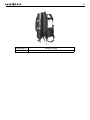
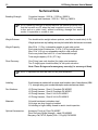
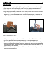
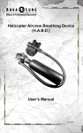
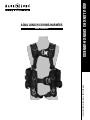
AQUA LUNG H3 DIVING HARNESS
AQUA LUNG H3 DIVING HARNESS
USER’S MANUAL
www.aqualung.com/militaryandprofessional
2
H3 Diving Harness User’s Manual
COPYRIGHT NOTICE
This owner’s manual is copyrighted, all rights reserved. It may not, in whole or in part, be copied,
photocopied, reproduced, translated or reduced to any electronic medium or machine readable form
without prior consent in writing from Aqua Lung International, Inc.
©2014 AQUA LUNG AMERICA
H3 Diving Harness
User’s Manual PN 18405
H3 Diving Harness (H3) Size #1 (L) PN 400800
H3 Diving Harness (H3) Size #2 (XL) PN 400801
You can contact a Technical Advisor via e-mail at:
[email protected]
[email protected]
[email protected]
TRADEMARK NOTICE
Aqua Lung® is a registered trademark of Aqua Lung America, Inc.
WARNINGS, CAUTIONS AND NOTES
Pay special attention to information provided in warnings, cautions and notes which are accompanied
by these symbols:
A WARNING indicates a procedure or situation that may
result in serious injury or death to the user.
A CAUTION indicates any situation or technique that will
result in potential damage to the product.
A NOTE is used to emphasize important points, tips and
reminders.
3
CONTENTS
FEATURES................................................................................................................4
H3 DIVING HARNESS COMPONENTS...................................................................4
USING NAUTIC® BUCKLES....................................................................................5
DONNING AND ADJUSTMENT PROCEDURES......................................................5
LOADING THE WEIGHT POCKETS.........................................................................6
OPERATING THE WEIGHT RELEASE POCKETS..................................................7
RESETTING THE WEIGHT RELEASE POCKETS...................................................8
NON-RELEASABLE WEIGHT...................................................................................9
GRIPLOCK™ CYLINDER BAND COMPONENTS.................................................10
THREADING THE GRIPLOCK™ CYLINDER BAND..............................................10
ADJUSTING THE GRIPLOCK™ CYLINDER BAND............................................... 11
SECURING THE GRIPLOCK™ CYLINDER BAND................................................ 11
PRE-DIVE CHECKLIST..........................................................................................13
POST-DIVE CHECKLIST........................................................................................14
HARNESS STORAGE.............................................................................................15
HARNESS SERVICE LIFE......................................................................................15
HARNESS SHELF LIFE..........................................................................................15
ATTACHING THE HARNESS TO THE BUOYANCY CELL.....................................16
PART NUMBERS AND SPARE PARTS LIST..........................................................18
ACCESSORIES......................................................................................................18
TECHNICAL DATA..................................................................................................20
ANNUAL INSPECTION & SERVICE RECORD......................................................21
H3 DIVING HARNESS DIVER RECOVERY PROCEDURE...................................22
WARRANTY INFORMATION..................................................................................26
4
H3 Diving Harness User’s Manual
Features
Description: The H3 Diving Harness is a strength-rated equipment harness specifically designed for
surface-supplied or saturation diving applications.
Design: Jacket style harness with integrated weights, cylinder straps and, attachment points.
Functions: 1. Secure attachment of umbilical or lifeline to the diver.
2. Attachment of weights, emergency gas supply (bailout) or accessories.
3. Recovery/lift of diver and equipment from the water in an emergency.
NOTE: The lifting points for diver recovery are clearly labelled “EMERGENCY USE”.
Sizes:
The harness is adjustable to fit a large spectrum of body shapes and sizes:
SIZE #1 - LARGE - Waist size 30 - 38 inches (76 - 97 cm).
SIZE #2 - EXTRA LARGE - Waist size 38 - 46 inches (97 - 117 cm).
H3 Diving Harness Components
• (a) Two point extraction D-rings
Note: This d-ring is for emergency recovery
of divers only.
• (b) Attachment D-rings
• (c) Chest strap w/ Nautic® buckle
• (d) Torso slide adjuster
• (e) Waistband w/ Nautic® buckle
• (f) Crotch straps
• (g) Universal comfort pad
• (h) Single point extraction D-ring
Note: This d-ring is for emergency recovery
of divers only.
• (i) Dual GripLock™ cylinder bands
• (j) Non-releasable weight (10 lb. max)
• (k) Double action weight release system
1. Two 25 lb. (11.3 kg.) weight pockets
2. Two 12.5 lb. (5.67 kg.) weight pouches
3. Two securing rods w/ handle
h See Note
g
See Note
a
b
See Note
a
b
c
d
i
d
j
1
1
2
2
k
k
3
b
f
f
e
b
b
b
3
5
READ ALL INSTRUCTIONS PRIOR TO USE
The H3 Diving Harness is intended for individual use and it should be fitted to a specific individual diver.
It is essential that the harness fits the diver correctly.
Using Nautic® Buckles
1. The buckle is fastened by pressing the male and female half-buckles together until they engage (i.e.
snap) into position (Fig. 1).
2. The buckle is unfastened by squeezing the two movable release tabs together until the halfbuckles disengage (Fig. 2).
Squeeze to Release
Male Half-Buckle
Female Half-Buckle
Squeeze to Release
Figure 1
Figure 2
Donning and Adjustment Procedures
CAUTION: A improperly adjusted or loose harness will be uncomfortable and may shift
during use thereby compromising performance, particularly in an emergency.
The harness must be adjusted to fit snugly around the waist, over the shoulders and through the crotch.
1. Secure emergency gas supply (bailout) to the harness using the two GripLock™ cylinder bands
(Follow the procedure in the section: Securing the GripLock™ Cylinder Band).
2. Don the harness and have the tender support the cylinder in the correct position on your back.
3. Connect the Nautic® buckles on the waist band by pushing the male and female half-buckles together until they snap into position. Tighten the waistband webbing strap by pulling the webbing
through the male half-buckle until a snug fit is achieved. Tuck the webbing tail out of the way. Repeat
the same process for the chest strap.
4. Release the hook and loop retainer tabs on one of the vertical torso adjustment straps. Thread the
webbing through the metal adjuster until a snug fit is achieved through torso. Re-fasten the hook
and loop retainer tabs. Repeat the same process on the other vertical torso adjustment strap.
6
H3 Diving Harness User’s Manual
5. Bring the two crotch straps with male half-buckles between your legs and fasten them to the lower
female half-buckles on the front of the harness.
6. Release the hook and loop retainer tabs on one of the crotch straps. Adjust the crotch strap by pulling
the webbing through the male half-buckle until a snug fit is achieved. Roll up the tail of the crotch strap
and re-fasten the hook and loop retainer tabs. Repeat the same process on the other crotch strap.
NOTE: The webbing tail of each crotch strap must be rolled up and the hook and loop retainer
tabs must be re-fastened in order to prevent strap pull through.
7. Load the weight release pockets.
Loading the Weight Release Pockets
1. Fill each 12.5 lb. weight pouch (four weights max) with equal amounts of weight for optimum balance,
preventing the tendency to roll to one side during the dive.
2. Load each 12.5 lb. weight pouch into the left and right weight release pockets as follows:
a. Open the top flap on each weight release pocket (Fig. 3).
b. Slide the loaded weight pouch into the weight release pocket (Fig. 4).
c. Close the top flap and ensure that the hook and loop tab is closed correctly (Fig. 5).
Figure 3
Figure 4
Figure 5
7
Operating the Weight Release Pockets
1. Grab the pull tab on the side of the weight pocket and pull forward (Fig. 6). This will release the hook
and loop retainer and expose the pull handle loop previously covered by the pull tab. (Fig. 7)
Figure 6
Figure 7
2. Insert thumb into pull handle loop and pull to the front. This will disengage the end tabs of the pull
handle and extract the securing rod from the underside of the weight pocket, which in turn will release
the weight pockets (Figs. 8 - 10).
Figure 8
Figure 9
Figure 10
8
H3 Diving Harness User’s Manual
Resetting the Weight Release Pockets
1. Re-insert the securing rod through the cylindrical loops on the underside of the weight pocket. The
rod must be inserted all the way in until the end is visible through the end of the rear loop (Figs. 11 - 13).
Figure 11
Figure 12
Rod Out
Rear Loop
Figure 13
2. Re-insert the end tabs of the pull handle into the sleeves on the front of the weight pocket (Fig. 14).
Ensure that the retention cords are tucked away (Fig. 15). Replace the pull tab over the pull handle and
secure using the hook and loop retainer pads.
Secure
Cord
Figure 14
Figure 15
9
Non-Releasable Weight
The harness is designed with two internal weight pockets capable of holding two block or soft weights.
This pocket is located on the inside of the harness (under the comfort pad). Each pocket can hold a maximum of 5 lb. of weight. A hook and loop closure secures the weight in the non-release pocket.
1. Lift up the universal comfort pad to expose the nonrelease weight pocket. Open flap on weight pocket
and insert weight into each side of the non-release
pocket (Fig. 16).
Figure 16
2. Secure hook and loop closure on non-release
pocket. Place universal comfort pad back on harness,
secure with hook and loop tabs to harness (Fig. 17).
Figure 17
10
H3 Diving Harness User’s Manual
Griplock™ Cylinder Band Components
Micro Adjustment
Bail
Lever
Bail Slot
Macro Adjustment
Threading the Griplock™ Cylinder Band
1. Remove the bail from both cylinder bands (Fig. 18). Face the GripLock™ patch up and insert the cylinder
bands right to left through the upper and lower cylinder band retaining straps (Fig. 19).
GripLock™
Patch
Cylinder Band
Retaining Straps
Figure 18
Figure 19
11
2. Insert the open end of the cylinder band into the large opening of the bail, around the slide bar and
out the small opening of the bail (Fig. 20). Secure the hook and loop on the band to hold the bail in
place (Fig. 21). Repeat process for other cylinder band.
Figure 20
Figure 21
Adjusting the Griplock™ Cylinder Band
NOTE: The GripLock™ cylinder band adjusts for all standard cylinder diameters and is ready
for use with an aluminium 80 cf (7.25 inch / 184 mm) cylinder when the BC leaves the factory.
1. There are three diameter settings (Fig. 22) for cylinder size: A. (large cylinder), B. (AL 80 cf; 7.25 in
/ 184 mm), C. (smaller cylinder). Adjust the macro adjustment for the proper size cylinder. Secure
hook and loop on the band to retain macro preset (Fig. 23).
Macro Presets
C
B
A
Figure 22
Figure 23
Securing the Griplock™ Cylinder Band
NOTE: There is no need to wet the GripLock™ cylinder band prior to securing it to the cylinder.
When properly adjusted, the cylinder band will retain it’s tension. If adjustment is necessary for
a larger or smaller size cylinder (pre-set for use on an aluminum 80 cf cylinder 7.25 inch / 184
mm), follow the procedure in the section: Adjusting the GripLock™ Cylinder Band.
12
H3 Diving Harness User’s Manual
WARNING: Check that the macro adjustment is set for the appropriate size cylinder.
Failure to do so may result in the cylinder slipping during the course of a dive.
NOTE: Pull the micro adjustment only until it is snug against the cylinder. If the lever is difficult to
close, the micro adjustment is too tight. Loosen the micro adjustment and close the lever to secure
GripLock™ band to cylinder. If it is difficult to remove the GripLock™ band from the cylinder, this
is an indicator that the micro adjustment was too tight when installed.
1. Make sure the cylinder valve air outlet is facing the back of the harness. Secure the upper GripLock™
band first to check for proper cylinder placement followed by the lower GripLock™ band. For optimum
cylinder retention, center the GripLock™ buckle assembly on the curve of the cylinder. Connect the bail
into the bail slot of the lever. Hold the lever and pull the GripLock™ patch end of the webbing to tighten
the micro adjustment (Fig. 24). Secure the hook and loop webbing on the micro adjustment (Fig. 25).
Figure 24
Figure 25
2. Push the lever forward until it stops in the pre-locked position (this keeps your fingers from being
caught in the lever) (Fig. 26). Push the lever down into the locked position. Verify the lever is secured in
the locked position (Fig. 27). Once the cylinder band is set up, further adjustment is typically not needed.
Repeat procedure to secure lower cylinder band.
Figure 26
Figure 27
WARNING: Verify the tension of the GripLock™ cylinder band prior to every dive. Failure to
do so may result in the cylinder slipping during the course of a dive.
13
Pre-Dive Checklist
Diver Name_____________________________ Date_____________
Harness Number_________
WARNING: Before each use, the harness must be given a thorough visual inspection
and functional test. NEVER dive with a harness that shows signs of damage until it has
been repaired and reinspected.
Initials
______ 1. Visually inspect harness thoroughly to ensure all components are in good condition.
NOTE: Pay particular attention to lifting points including support webbing and stitching.
______ 2. Connect and disconnect each Nautic® buckle to confirm proper operation.
______ 3. Inspect all stitching, webbing and hook/loop material for cuts, tears and abrasion
damage.
______ 4. Confirm that weight release rod is inserted correctly at bottom of each weight pocket.
______ 5. Don harness and adjust for proper fit.
______ 6. Install weights into weight pouches as needed.
______ 7. Install loaded weight pouches into weight release pockets.
______ 8. Verify that all harness straps are connected properly and operate correctly.
WARNING: DO NOT use a damaged or deteriorated harness.
Remarks
Divers Signature
Diving Supervisor Signature
14
H3 Diving Harness User’s Manual
Post-Dive Checklist
Diver Name_____________________________ Date_____________
Harness Number_________
NOTE: Avoid prolonged exposure to sun, extreme heat and heavy pool chemicals to
prevent deterioration. To prevent premature damage, thoroughly rinse the harness
with fresh water at the end of each diving day using the following procedures.
Initials
______ 1. Remove weight pouches from weight release pockets.
______ 2. Visually examine harness thoroughly to ensure that all components are in good
condition.
NOTE: Pay particular attention to lifting points including support webbing and stitching.
______ 3. Thoroughly rinse harness and pouches with fresh water. Ensure Nautic® buckles
are clear of debris.
______ 4. Hang harness to air dry, out of direct sunlight, before storing.
______ 5. If dirty, clean using a solution of warm water and household grade mild soapy
detergent. A soft brush may be used as required. Thoroughly rinse with fresh
water. Hang to air dry.
Remarks
Divers Signature
Diving Supervisor Signature
15
Harness Storage
• Harness must be completely dry for storage. Do not store in a damp condition or area.
• Store the harness on a hangar away from direct sunlight in a dry, well ventilated area.
• Do not store near sources of heat such as radiators.
• Do not store in a warm, humid environment where mold or mildew can contaminate the harness.
• Avoid prolonged exposure to sun, extreme heat and heavy pool chemicals to prevent deterioration.
Harness Service Life
• Every in-use harness (i.e. which has been used in-water) is to be discarded after 5 years or earlier
if dictated by poor physical condition.
• When discarded the harness should be destroyed to prevent re-use.
• Reference: IMCA D 018, Code of Practice for The Initial and Periodic Examination, Testing and
Certification of Diving Plant and Equipment.
Harness Shelf Life
• Each unused harness is to be discarded after 10 years regardless of use.
• When discarded the harness should be destroyed to prevent re-use.
• Reference: IMCA D 018, Code of Practice for The Initial and Periodic Examination, Testing and
Certification of Diving Plant and Equipment.
NOTE: More stringent discard criteria may be applied depending on conditions of use.
16
H3 Diving Harness User’s Manual
Attaching the Harness to the Buoyancy Cell (Optional Use Only)
The H3 diving harness is designed to accept a standard Apeks WTX 3 buoyancy cell.
1. Align tank band slots on buoyancy cell with cylinder band retaining straps on harness (Fig. 28). Place
buoyancy cell on top of the harness with inflator facing away from the harness (Fig. 29).
Figure 28
Figure 29
17
2. Remove the bail from both cylinder bands and position bands so the GripLock™patch is face-up. Insert
the cylinder bands right to left through the upper and lower oval slots on the buoyancy cell, under both
cylinder band retaining straps and out the opposite oval slots. (Figs. 30 - 33).
GripLock™
Patch
Figure 30
Figure 31
Figure 32
Figure 33
3. Place the bail back onto both cylinder bands (Fig. 34.)
(Refer to section: Threading the GripLock™ Cylinder Band).
Figure 34
4. To adjust and secure the harness with buoyancy cell to a cylinder, refer to sections:
• Adjusting the GripLock™ Cylinder Band.
• Securing the GripLock™ Cylinder Band.
18
H3 Diving Harness User’s Manual
Part Numbers and Spare Parts
AQA PART #
400800
400801
400811
400812
400806
428230
769148
DESCRIPTION
Diving Harness (H3), Complete, Size 1
Diving Harness (H3), Complete, Size 2
Diving Harness (H3), Hi-Vis, Size 1
Diving Harness (H3), Hi-Vis, Size 2
Weight Pouch, 12.5 lb.
Tank Band, GripLock™ / Wrapture, Pckgd
Comfort Pad, Pckgd
Accessories
AQA PART #
400807
DESCRIPTION
Accessory Pouch w/ Clips
AQA PART #
400803
DESCRIPTION
Bridle, Diver Recovery
19
AQA PART #
388032
DESCRIPTION
Buoyancy Cell, WTX3, Apeks
20
H3 Diving Harness User’s Manual
Technical Data
Breaking Strength: Complete Harness - 2200 lb. / 1000 kg / 9800 N
All D-rings and Hardware - 2200 lb. / 1000 kg / 9800 N
NOTE: Breaking Strength is defined here as the maximum tensile load
that the harness can lift, when the load is applied correctly (i.e. directly
in-line and as a static load), without sustaining damage that would
render it inoperable or unsafe to use.
Weight Release:
Two double action weight release pockets, one fitted on each side (L & R)
Weight pockets are top loading and may be loaded after the harness is donned
Weight Capacity:
Max 25 lb. (11.3 kg.) releasable weights in each side pocket
Each side pocket contains two 12.5 lb. (5.67 kg) weight pouches
Max 10 lb. (4.5 kg) non-releasable weight in rear pockets
Each rear pocket can hold 5 lb. of non-releasable weight
Total weight capacity: 60 lb. (27.2 kg)
Diver Recovery:
One D-ring (rear neck location) for single point extraction
Two D-rings (upper chest/shoulder) for two point extraction
Note: These D-rings are for emergency use only (i.e. recovery of diver)
NOTE: A spreader bar must be used for two point extraction.
Labeling:
Each harness is marked with a unique serial number, date of manufacture (MM/
YY), strength rating, part number/description and manufacturer details
Part Numbers:
H3 Diving Harness,
H3 Diving Harness,
H3 Diving Harness,
H3 Diving Harness,
Materials:
Optional Accessories:
Size #1 Complete PN 400800
Size #2 Complete PN 400801
Size #1 Hi-Vis PN 400811
Size #2 Hi-Vis PN 400812
All metal hardware is stainless steel
All d-rings are drop forged not welded
All stitching is high visibility thread to assist visual inspection
Accessory Pouch w/ Clips PN 400807
Diver Recovery Bridle (strength - rated) PN 400803
Buoyancy Cell, WTX3, Apeks (34 lb. / 15 kg lift) PN 388032
21
Annual Inspection & Service Record
Date
Harness #
Technician Name
Observations
Technician
Signature
22
H3 Diving Harness User’s Manual
H3 Diving Harness Diver Recovery Procedure
The recovery operation, and provision of suitable lifting equipment, is the legal responsibility of
the dive contractor. This diver recovery procedure is provided to assist the dive supervisor in
the use of the H3 Diving Harness.
USE OF H3 DIVING HARNESS: The H3 Diving Harness is designed to enable the recovery (i.e. lifting)
of an unconscious diver from the water onto a boat, platform or jetty equipped with a recovery hoist.
Lifting points for diver recovery are clearly labelled “EMERGENCY USE”. The harness provides 2 diver
recovery options:
1. One D-ring (rear neck location) for single point extraction.
2. Two D-rings (upper chest/shoulder) for 2-point extraction using a recovery bridle/spreader bar.
OBJECTIVE: The objective of the diver recovery procedure is to remove an unconscious diver from
the water to a place of relative safety (i.e. a location where the diver can receive medical assistance).
This must be accomplished quickly and efficiently and, if possible, without causing further injury to
the diver. When the diver is recovered, his diving apparatus must be removable without removal of
the diving harness. Time is always a factor.
ENVIRONMENTAL CONDITIONS: All operating scenarios are different but care must be taken if there
is a large swell or wave action. This may cause the recovery line to become slack then taut (i.e. rapid
raise then drop).
PROCEDURE FOR SINGLE POINT EXTRACTION
CAUTION: If the diver is recovered using the single point extraction procedure, the lifting
equipment could obstruct or cause damage to the first stage regulator of the EGS (bailout
system) when rigged in the cylinder “Valve Up” configuration. To prevent this, the EGS
should be rigged in a cylinder “Valve Down” configuration or, alternatively, the first stage
regulator should be turned away from the diver’s helmet. Diver recovery must be carried
out with maximum caution and attention at all times.
NOTE: Recovery equipment used must be rated to withstand 9 kN (2023 lb) with the diver
being lifted vertically.
23
RESCUE DIVER
1. Approach the diver and positively identify the single D-ring in the harness rear neck location (A).
2. Attach the recovery device/line/hoist to the single D-ring in the harness rear neck location (B).
3. Confirm to the surface support team that the diver is ready to be lifted.
4. Attend the unconscious diver as the recovery line is pulled up and the diver is lifted from the water:
a. Ensure that the recovery line does not snag on any equipment.
b. Keep hold of the unconscious diver: in swell conditions this reduces slack in the recovery line.
c. Ensure that the unconscious diver does not swing against the side of the boat or structure.
A
B
SURFACE SUPPORT TEAM
1. Deploy the recovery equipment and ensure that the rescue diver has sufficient line to work with.
2. Ensure that the recovery line is kept clear of obstructions or snag hazards at all times.
3. When directed by the supervisor, take up the slack in the recovery line and lift the diver carefully.
4. When the diver is recovered, and when directed by the supervisor, remove the diving apparatus as
follows: remove the helmet, unclip the emergency gas supply (bailout) cylinder tank bands (x 2), and
unclip the umbilical from the harness.
5. The harness, with recovery line attached, should remain on the diver (i.e. diver kept under positive
control) until directed to remove it.
24
H3 Diving Harness User’s Manual
H3 Diving Harness Diver Recovery Procedure
The recovery operation, and provision of suitable lifting equipment, is the legal responsibility
of the dive contractor.This diver recovery procedure is provided to assist the dive supervisor in
the use of the H3 Diving Harness.
PROCEDURE FOR 2-POINT EXTRACTION
CAUTION: If the diver is recovered by the 2 point extraction procedure, the lifting equipment
could obstruct or cause damage to the breathing gas supply system of side block equipped
diving helmets. For this reason the single point extraction procedure is the preferred recovery
procedure for diving helmets equipped with side blocks. Diver recovery must be carried out
with maximum caution and attention at all times.
NOTE: This procedure requires a strength-rated recovery bridle or spreader bar. Recovery
equipment must be rated to withstand 9 kN (2023 lb) with the diver being lifted vertically.
RESCUE DIVER
1. Approach the diver and positively identify the two D-rings in the upper chest/shoulder location (C1 and C2).
2. Attach each leg of the recovery bridle/spreader bar to one of these D-rings (D).
3. Ensure that the recovery bridle/spreader bar and legs are laid out and orientated correctly (E).
4. Ensure that the recovery line is attached securely to the recovery bridle/spreader bar (F).
5. Confirm to the surface support team that the diver is ready to be lifted.
6. Attend the unconscious diver as the recovery line is pulled up and the diver is lifted from the water:
a. Ensure that the recovery line and recovery bridle/spreader bar are
clear of the diver’s helmet and do not snag on any equipment.
F
b. Keep hold of the unconscious diver: in swell conditions this reduces
slack in the recovery line.
c. Ensure that the unconscious diver does not swing against the
side of the boat or structure.
C1
C2
D
E
25
SURFACE SUPPORT TEAM
1. Deploy the recovery equipment and ensure that the rescue diver has enough line to work with.
2. Ensure that the recovery line and recovery bridle/spreader bar are kept clear of obstructions or snag
hazards at all times.
3. When directed by the supervisor, take up the slack in the recovery line and lift the diver carefully.
4. When the diver is recovered, and when directed by the supervisor, remove the diving apparatus as
follows: remove the helmet, unclip the emergency gas supply (bailout) cylinder tank bands (x 2), and
unclip the umbilical from the harness.
5. The harness, with recovery line attached, should remain on the diver (i.e. diver kept under positive
control) until directed to remove it.
26
H3 Diving Harness User’s Manual
Warranty Information - Military & Commercial
All requests for warranty transactions must be accompanied by an in-service date and by documentation
of Aqua Lung America Inc. factory recommended inspection/maintenance* in accordance with this Manual
whenever returning your military or commercial product for warranty service.
The Aqua Lung® One Year Limited Warranty™
Aqua Lung America, Inc. warrants to the original purchaser for a period of one year from the purchase date
that the product will be free from defects in material and workmanship; provided that it receives normal use,
proper care and prescribed maintenance subject to those restrictions stated below. This limited warranty is
extended only to the original purchaser for purchases made from Aqua Lung America, Inc.™ an authorized
Aqua Lung® dealer, and is not transferable. With this warranty, Aqua Lung America, Inc. reserves the right
to repair or replace the product at its sole discretion.
ALL WARRANTIES, INCLUDING BUT NOT LIMITED TO IMPLIED WARRANTIES, OR MERCHANTABILITY
AND FITNESS FOR A PARTICULAR PURPOSE ARE LIMITED IN DURATION TO A PERIOD ENDING ONE
YEAR FROM THE DATE OF PURCHASE OR IN-SERVICE DATE.
WARNING: It is dangerous for untrained and uncertified persons to use the equipment covered
by this warranty. Therefore, use of these products by an untrained person renders any and all
warranties null and void. Use of Surface Supplied or SCUBA equipment by anyone who is not
a certified diver or receiving training through a recognized training certification agency (either
military or commercial), shall render void all warranties, expressed or implied.
AQUA LUNG AMERICA, INC. DISCLAIMS AND EXCLUDES ANY LIABILITY FOR INCIDENTAL
OR CONSEQUENTIAL DAMAGES. IN SOME STATES WHICH DO NOT ALLOW EXCLUSION OF
LIABILITY, THIS MAY NOT APPLY TO YOU.
Restrictions
The following restrictions apply to this warranty:
• This warranty does not extend to abrasion or seam separation caused by chemical attack, including
prolonged exposure to chlorine.
• This warranty does not extend to damages caused by improper use, improper maintenance, neglect,
unauthorized repairs, modifications, accident, fire or casualty.
• Cosmetic damage, such as scratches, fraying, and nicks are not covered by this warranty.
• This warranty does not extend to products that have been not properly inspected or maintained in
accordance with the recommended Aqua Lung America, Inc. factory requirements.
• Failure to meet any of the above requirements will render the warranty null and void.
WARNING: Failure to maintain this equipment and perform the required Aqua Lung America,
Inc. factory maintenance in accordance with the factory manual renders any and all warranties
expressed or implied, null and void.
* Reference Annual Inspection & Service Record provided in manual.
AQUA LUNG H3 DIVING HARNESS
AQUA LUNG H3 DIVING HARNESS
USER’S MANUAL
©2014 Aqua Lung International
Literature P/N 18405 Rev. 8/14
www.aqualung.com/militaryandprofessional
2340 Cousteau Court • Vista, CA 92081
Phone (760) 597-5000 • Fax (760) 597-4900
www.aqualung.com/militaryandprofessional