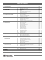
1
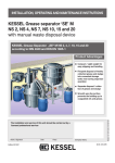
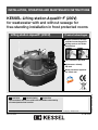
INSTALLATION, OPERATING AND MAINTENANCE INSTRUCTIONS KESSEL-Lifting station Aqualift 쏐F (230V) for wastewater with and without sewage for free-standing installation in frost protected rooms Lifting station Aqualift쏐 (230 V) Product advantages Simple connection through moulded connecting pieces Drilling surfaces for further Connections Fully automatic operation Maintenance-friendly PE-tank General technical approval no. Z-53.2-424 LGA Type-tested and monitored Installation Commissioning Instruction The installation and service of this unit should be carried out by a licensed professional servicer Name/Sign Edition 07/2010 Date Town Company - Telephone No. Subject to technical amendment ith ed w ante guar quality tested Nr. 206-817EN Table of contents 1. Safety information 2. General 3. Technical data ...........................................................................................................Page 2.1 Application Scope................................................................Page 5 3.2 Pump ...................................................................................Page 6 2.2 3.1 3.3 4. Installation and assembly 5. Electrical connections 6. Commissioning 5.3 Installation, wiring ................................................................Page 13 5.1 5.2 11 General information .............................................................Page 12 Assembly of the switchgear.................................................Page 12 System Commissioning .......................................................Page 15 6.2 General information .............................................................Page 15 Pressure Outlet....................................................................Page 15 Normal operation .................................................................Page 16 Manual Pump Start..............................................................Page 16 Additional functions .............................................................Page 16 Factory Pre-settings ............................................................Page 17 Checking the settings ..........................................................Page 17 Changing settings................................................................Page 18 6.10 Operational Test ..................................................................Page 18 7.3 Notes for electrical control unit ............................................Page 20 8.3 Correction of Warnings and Errors ......................................Page 22 7.1 7.2 8.1 8.2 8.5 8.6 9.1 9.2 9.3 10. Replacement parts and accessories 10.1 10.2 13. Handover record 9 6.3 6.1 8.4 12. Declaration of conformity Connection of drainage pipes..............................................Page 9 Completion of Control Unit Connections..............................Page 14 6.9 11. Warranty Area of Installation...............................................................Page 8 5.4 6.8 with Connection plan 8 3 Level sensor / control........................................................Page 4.2 6.7 9. Control unit Lifting Station Performance Curve.......................................Page 6 4.3 4.1 6.6 troubleshooting Dimensions..........................................................................Page 5 Electrical Control Unit ..........................................................Page 6.5 8. Malfunctions, Errors and Description of the system ....................................................Page 3.4. 6.4 7. Inspection and maintenance 4 Notes on the pump ..............................................................Page 19 Notes on the aerating device ...............................................Page 19 General Comments .............................................................Page 20 Display of Warnings and Errors ...........................................Page 21 General Failures ..................................................................Page 23 Illogical switching sequences ..............................................Page 25 What to do when….... ..........................................................Page 25 General description .............................................................Page 26 Display and Operation Buttons Description .........................Page 26 Connection plan...................................................................Page 27 Accessories .........................................................................Page 29 Replacement Parts ..............................................................Page 30 ...........................................................................................................Page 33 ...........................................................................................................Page 34 ...........................................................................................................Page 35 1. Safety instructions General safety precautions During installation, operation, maintenance or repairs to the system, please observe the accident prevention regulations, the applicable DIN and VDE standards and guidelines, and also the regulations of the local energy and supply companies. The systems may not be operated in explosive areas Electrical hazards This system contains electrical voltages and controls rotating mechanical parts. Non-observation of the operating instructions could lead to serious damage, injury or even fatal accidents. The system must be securely disconnected from the mains supply before commencing any work on it. The local master switch and the cut-outs must be turned off, i.e. switch the system to zero-potential and take precautions to ensure it cannot be switched on again. If only cut-outs are available, these must be switched off and a sign attached to prevent third parties from switching the main fuse on again. VDE 0100 applies to all electrical work on the system. The switchgear and the level control are under voltage and may not be opened. Only electricians may work on the electrical equipment. The term 'electrician' is defined in the VDE 0105. Steps must be taken to ensure that the electrical cables and all other electrical system parts are in a fully functional condition. If any parts are damaged, the system may not be operated and/or must be immediately shut down. ! Risk of burning fingers and hands The driving engine may become very hot during operation Risk of injury to fingers and hands The pumps are equipped with a closed impeller. Therefore work on the pump may only be carried out if the power supply has been disconnected and the rotating parts have stopped rotating. Take care on sharp edges during maintenance or repair work. Risk due to heavy weights The lifting system models with one pump weigh around 45 kg, and with two pumps around 84 kg. The systems may only be lifted or mounted by two persons with appropriate care wearing protective equipment (e.g. protective shoes). The pumps may only be removed slowly or placed in the pump flange opening by two persons (if suitable precautions to prevent slipping have been taken). 3 1. Safety instructions Health risk The wastewater system transports wastewater that contains faeces; in turn this faeces may contain harmful substances. Whenever working on the system, always ensure that there is no direct contact between the wastewater and/or soiled system parts and your eyes, mouth or skin. In the event of direct contact, clean the affected part of your body thoroughly and disinfect if necessary. It is also possible that the atmosphere in the tank may be harmful. Therefore before opening the cleaning aperture (or removing the pump) ensure that the respective room is adequately ventilated or provide for (forced) ventilation during the opening process. Noise pollution When the pump is operated, a noise level is created that may be a nuisance depending on how the pump is installed. If there are maximum noise level stipulations that need to be observed, appropriate measures need to be taken. The sound damping set from KESSEL may also be helpful here. Risk of explosion The inside of the tank is considered to be explosive within the meaning of EN 12050 because the biological digestive process may create flammable gases (hydrogen sulphide, methane gas). Therefore, when unscrewing the pump or the cleaning aperture lid or any other parts, ensure that the room is adequately ventilated or provide for (forced) ventilation during the opening process. Whilst the tank is open, it is forbidden to smoke or carry out any other activities in the respective room that could cause the gas to ignite (e.g. operation of electrical devices without encapsulated motors, metalworking etc.). Dear Customer, Thank you for choosing a KESSEL product. This product passed strict internal quality control standards before leaving the factory. Please check now to make sure that all parts have arrived and have arrived undamaged. In the case that damage occurred during shipping, please see the Warranty section at the end of this manual. Before this Aqualift F lifting station is installed and placed into operation, it is in your best interest to thoroughly read through this installation and operation manual and follow it closely. KESSEL 4 2. General 2.1 2.1 Area of application This lifting station pumps wastewater with and without sewagethat occurs below the sewer and backwater level fully automatically into the sewage system in accordance with the requirements of DIN 1986. They are only suitable for use for domestic wastewater, for example in single family and multifamily homes, hotels and restaurants, department stores, hospitals, schools or similar commercial applications. In case the area of application will not allow down time due to the breakdown of a single pump system, the lifting station must be equipped with a second pump of the same capacity which switches on immediately when required (twin station instead of single station). The KESSEL lifting station Aqualift® F has been designed for free-standing installation in frost-protected rooms. The included control unit must be mounted in a flood-proof, dry and frost-protected area. The systemʼs wastewater pumps are equipped with a single-vane impeller and have a free passage of 40 mm. The pressure pipe connection must be size DN 80 at a minimum, the ventilation pipes must be size DN 70 at a minimum. Abrasive media must be kept away from the pumpʼs impeller. The systems are suitable for constant wastewater temperatures up to 35°C. A maximum temperature of 60°C is permissible briefly (up to 10 minutes). 2.2 Description of the system The KESSEL Aqualift® F lifting station operates on alternating current and consists of the following main parts: 1.2 1.5 1.1 1.7 1.3 1.4 1.6 1.8 1. 1.1 1.2 1.3 1.4 1.5 1.6 1.7 1.8 A gas and water tight collecting tank made of LLDPE (low linear density polyethylene), with A wastewater pump with 5 meter power cable Pneumatic level control with 5 m cable Access / cleaning opening Inlet connection for DN 100 drainage pipe DN 70 ventilation connection DN 40 connection for emergency manual diaphragm pump DN 100 outlet connection with integrated non-return flap and flap release lever Areas for connection of additional inlets 5 2. 2. Electrical control unit (see illustrations in chapter 9) 3. 3. Accessory parts (not illustrated) 3.1 Brackets with screws and dowels for fixing the pump body to the floor 3.2 Rubber connection coupling stainless steel clamps for the pressure pipe connection 3.3 Sound-insulating underlay mat Mono: Art. no. 28692 Duo: Art. no. 28693 A detailed description of the system set-up can be found in chapter 10, Spare parts. 3. Technical Data 3.1 Dimensions Single 1.1 kW lifting station with DN 100 pressure outlet, Article Number 28646 DN100 Ø110 DN70 Ø40 DN32 Zulaufhöhe 180 475 Ø110 DN100 Ø75 154 525 ISO-Ansicht 564 6 3. Technical Data 3.2 Pump Type Nominal capacity (P2) Rated capacity (P1) Operating voltage Rated frequency Nominal current Start-up current Capacitor Fuse Connection cable Pumping medium temperature Weight (pump) Protection Class Operational class 230 V - 1,1 kW 1,1 kW 1,7 kW 230 V 50 Hz 7,3 A 18,5 A 40 µF; 400 V AC DB 10 A slow blow 5 m length, 7 x 1,5 mm2 35 °C 30 kg IP 68 ( up to 3 m) S3 60% max operation times < 70 db Noise level Lifting station performance curve Förderhöhe [m] 9 min nach DIN EN 12056-4 (Vmin = 0,7 m/s) Q Qmin nach DIN 1986 (vmin = 0,7m/s) für DN 80 für DN 100 8 7 6 5 4 3 2 1 0 0 0 4 2 8 12 4 16 20 6 7 24 28 8 32 36 10 40 44 12 48 14 Förderstrom Q [m3/h] [l/s] 3. Technical Data 3.3 Pump volume The factory set pumping volume is 20 liter which is controlled by the pneumatic switch and the control unit. 3.4 Electrical Control Unit 3.4.1 General technical data Control Unit Dimensions (L x W x H) Control Unit Weight 180 x 200 x 70 mm 1100 g Maximum elevation of system: 0 bis 40 °C 10 bis 80 % non-condensing 2000 m above sea level Ambient conditions Allowable temperature range: Allowable humidity: Power consumption Approx 5 VA (without motor) 3.4.3 Inputs ʻInʼ and ʻLevelʼ level inputs Operational current – 6 V DC, switching power each 10 mA Thermal motor switch Supply current 12 V DC Switching power ON = 9 mA Switching power OFF = 5 mA 3.4.4 Outputs Potential free contact Switch: opener, middle contact, close; max. 42 V AC/ 0,5 A without system internal protective switch for inductive loads. Pump-Motor Connection of the protective lead and the single phase windings of motor. Protective class Class 1 with function grounding of the secondary electronics circuit (PELV) Protective rating IP 54 with screwed shut cover and cover gasket 3.4.2 Power Supply Operating power 230 V AC 1~/N/PE 50 Hz ± 10% Power cable 1.7 meter power cable with protective contact connection in control unit Required power supply fuse max. 16A (to be provided on-site) 8 4. Installation and assembly IMPORTANT: The electric switch unit must be stored in a frost free and weather protected area prior to installation. If the control unit is to be connected at a later date, it should be properly stored as stated above. Caution Danger due to heavy weights. The lifting station weighs approx. 45 kg (single system). The parts may only be lifted and/or assembled using suitable equipment and exercising appropriate caution. If the system is dropped, this can lead to irreparable damage to system parts (e.g. pump) or the entire system. Such damage is not covered by the warranty. INSTALLATION SITE: The KESSEL lifting station Aqualift® F has been designed for free-standing set-up in frost-protected rooms. The area of installation should be protected against flooding. A submergence of the lifting station for more than 24 hours can cause the system to stop operating and can lead to irreparable damage. The included control unit should be mounted in a flood protected, dry and frost proof room. Mounting bracket Lifting station body Floor mount The following parts are included in the scope of supply (see section 2.2): - Collecting tank with all components mounted - Electric Control Unit (plug-in-ready) - Accessories Vibration matt (optional) Floor 4.2 Connection of drainage pipes All drainage pipes connected to the lifting station must be installed so that they can completely drain into the lifting station (no standing water in the drainage pipes). All pipe connections must be flexible and sound insulated. There are two types of connections possible: I. Use of existing integrated connecting spigots on the tank (for connection of main inlet pipe, ventilation and manual diaphragm emergency pump according to Fig.A) Capped spigots should be cut off as shown on the diagram (at by cutting off the "front cap" as shown in Fig. C.) Ventialtion DN 70 (ODa=75mm) 4.1 Area of installation In order to prevent improper installation, service or repair of the lifting staition, it must always be installed in such a way that there is sufficient access to all areas of the lifting station and replacement of all components is possible. DIN 1986 requires at least 60 cm of access space on all sides of the system. The system must be set up in a appropriate area of a room, aligned horizontally and placed on a sound-insulating matt (available as an accessory from KESSEL). The lifting station must be properly secured to the floor with the included. This will prevent unwanted movement / twisting of the system during start-ups and operation. 9 Emergency pump conenction DN 32 (ODa=40mm) Inlet Connection DN 100 (ODa=110m m) Fig. A: Single pump system The socket side of a standard drainage pipe can now be fitted over the cut off spigot (lubricated appropriately). (see Fig. C) 4. Installation and assembly Alternatively, the connection of a plastic pipe with DN 100 for the inlet or DN 70 for ventilation can be carried out using rubber type connection couplings with stainless steel fastening brackets. To prevent damage to the plastic spigots during tightening of the stainless steel clamps, a suitable steel supporting ring must be inserted into the outer end of the spigot (see Fig. D) Saw off inlet cap II. Connection of additional inlets on the flat connection surfaces on the side of the lifting station body – additional inlets can be connected to the body by drilling out the proper sized hole, inserting a properly sized pipe gasket and then inserting a lubricated drainage pipe (see Fig. E) (Hole saw drill connectors and pipe gaskets available from KESSEL) Ventialtion pipe seal Drilled opening Pipe connection Lifting station body Inlet connection Ill. E * KESSEL-Accessories Lifting station body Ill. C: Pipe connection Hose clamp IMPORTANT In the case that additional inlets are connected to the side of the lifting station body, it should be noted that during normal operation the wastewater level will reach the base of the main inlet spigot (or slightly above). Any additional inlet connection below this level will mean that wastewater will stand in the drainage pipes which, over time, could lead to blockages of the inlet pipe. Pipe sleave saw off inlet cap Support ring Hose clamp Ill.D: 10 4. Installation and assembly The inlet pipe must be laid as straight as possible and aat a gradient to the KESSEL lifting station in accordance with EN 12056. Inlets connected too low on the tank could result in blockages of the inlet pipe (please see the ʻImportantʼ section on page 10). Connection to the tank can be carried out as described under section I or II above. The ventilation pipe equalized the air pressure inside the lifting station which occurs during filling or pumping out of the pump body. According to DIN 1986 the ventilation pipe must have as least the DN 70 size and be connected directly through the roof of the building to ambient air, which will prevent nuisance odours. Connecting the ventilation pipe to the lifting station body can be handled as described in the previous section 4.2 (Connection of drainage pipes). The pressure pipe for pumping out collected wastewater into the adjoining sewer should be connected directly to the outlet pressure pipe. To reduce noise and force transfer into the pressure pipe the supplied rubber pressure connection coupling must be used. It should be fitted at least 4 cm over the outlet spigot of the lifting station and be secured with a stainless steel pipe clamp. The supplied rubber pressure connection does not offer any type of lateral force connection which must be handled on-site, for example with pipe connection clamps secured to the wall or ceiling. According to the regulations of EN 12056, the pressure pipe must be routed above the backwater level and connected to a ventilated drainage pipe to the sewer. A gate closure valve should be connected on-site to the pressure pipe. The pressure pipe must be connected (see above) in such a way that no forces are transferred to the system and there is no direct contact with the building (structure-borne noise). No other drainage pipes or fixtures may be connected to the pressure pipe. Air-tightness and material strength must be guaranteed under pressure load. This must be checked during commissioning of the system. Non-return flaps installed in the pressure outlet pipe are available as accessories. DN 80 cast iron non-return flap (Article # 206-199) DN 100 cast iron non-return flap (Article # 206-198) Ventilation system (Article # 206-200) 11 4.3 Level sensor / control CAUTION: Prior to any work taking place on the control unit, pump or pressure switch, the main power supply to the system must be disconnected and secured against accidental activation. This system is equipped with a wastewater pump. Two wastewater levels are monitored to control the system (ON and ALARM levels). The pressure / level sensor is installed and pre-set at the factory. The pump activation (ON) level is set for a wastewater level of 160 mm, the alarm activation (ALARM) level is set for a wastewater level of 200 mm. The levels can be changed by re-setting the control unit if custom ON or ALARM levels are required. However, it is important that the ALARM level is not set too low to prevent unnecessary alarm signals as well as the ON level should not be set too high to prevent wastewater back-up into the inlet pipes as well as too frequent pump activation (for pumps manufactured on June, 2009 or earlier). 4.3.1 Custom setting of level sensor The ON pump activation level can be adjusted using screw 1 and the ALARM activation level can be adjusted using screw 2 as seen on the diagram. Turning the adjustment screw in the clockwise direction increases the activation level, turning in the counter clockwise direction lowers the activation level. Turning a screw half was around will adjust change the activation level by 10 mm. 2 1 until model year 12/2009 4.3.2 2 Level sensors (for Jan 2010 an on) The transparent air hose must be laid with a continuous upward slope to the control unit so that no condensation liquid can build up in the hose. Make sure that the hose is not looped or coiled up. If the air hose is too long it can be shortened on-site. The air house can be extended to a maximum length of 20 meters. The activation levels have be set at the factory and can be changed by control unit adjustments. Additional information is available from the KESSEL customer service department. 5. Electrical connections The pump power cable and level sensor cable have been connected to the control unit at the factory. Independent from this, the further instruction in this section of the manual must be followed. In the case installation work has already been done, this manuals instructions should be reviewed and checked to make sure all work on the system has been done accurately and correctly. Caution: Only certified electricians should perform the following work on this electrical system. Prior to any work being conducted on the control unit, motor or pressure switch, the system must be completely disconnected from its power source. Also it should be insured that the power is not accidentally re-connected during this work. 5.1 General instructions An external main switch must be installed for the control unit that can be used in an emergency to switch off all power to the system. This must be installed so that it is clearly visible. All cables entering the control unit must be secured with the included fastening nuts for strain / pull relief. Inlets to the control unit which are not used must be properly seals with the included plastic nuts. IMPORTANT: All the cables connected to the electrical switch unit must be fixed in place using suitable measures (e.g. cable ties) so that they do not cause a hazard in the 1-error case, i.e. if a connection becomes loose... Please heed national and local safety regulations. If these are not observed, personal hazard / injury may be the result. In addition, no liability or warranty will be granted. After work has been completed, the control unit housing cover must be sealed properly again to assure the control unit is protected from water /moisture and unallowed access. The level sensor cable should not be laid in the same conduit as the power cable or any other electrical cable to prevent electrical interference. 5.2 Control unit mounting The supplied control unit should be installed in an easily accessible location in a frost free, weather protected, flood free and properly ventilated area. The control unit should be mounted to a firm wall as eye level. To prevent elevated internal temperatures, sufficient air circulation should be available. The supplied template should be used to properly drill the four holes into the wall where the control unit will be mounted. The four supplied dowels should be inserted into these four holes, the control unit placed over the four dowels and the back wall of the control unit fixed to the dowels with the four supplied screws. 햲 Control unit cover hinges (2)) 햳 Plastic dowels (5x25mm) (4) 햴 Fastening screws (M3.5x30) (4) 햵 Cover screws (max 1 Nm torque)(4) 1 4 1 2 3 Control unit housing without electronics When the control unit cover is open the IP 54 protection class is no longer provided. Prior to operation, it should be confirmed that excessive moisture or spraying water will not negatively effect the system After any work is done on the control unit, the cover must be closed and properly fastened in order to provide the proper dust / moisture protection 12 5. Electrical connections 5.3 Installation, Cable connections All cable connections should be done as shown in the connection diagrams (see section 9). Break the seal in the control unit cable access hole as seen in illustration a, insert the cable as shown in b, and connect to the properly connection terminal as shown in c. When the connection is complete be sure to properly secure the plastic nut by hand – see illustration d. If a potential free contact is to be installed, please follow the technical information supplied with that part. The cable access ports at the base of the control unit which are not used should remain as they are and the protective seal should not be pierced. The pre-installed motor and level sensor cables have a standard length of 5 meter. The motor cable can be extended to a maximum length of 20 meters only with the use of a VDE approved extension connection. CAUTION: The transparent air hose on the level sensor transfers air pressures to the control unit which are monitored – a few important points concerning this follow: - This air hose must be laid with a continuous slope to the control unit. The hose should not be kinked, coiled, looped or rolled up. - Not following the above requirements can lead to improper pressure readings resulting in improper pump operations! Caution! Pressure switch cable must be layed with a constant downward slop to the lifting station. The cable should not be coiled or kinked Wrong Right 13 5. Electrical connections The individual connection tasks are listed in the following table and in the connection diagrams on page 28. The explanations in Section 9, Electric Control Unit, must also be heeded (position of the control elements, view of the inside of the control unit. Required Connections Connect batteries (Akkus up to 11/09) Power connection Motor cables and motor temperature sensor Level sensor Potential free contact (accessory number 80072) Single Pump Lifting Station - Follow all safety instructions! Description • Both 9-volt batteries must be connected to the circuit board • The power supply must offer a full pole main switch that is directly connected to the controls • The required fusing on-site must not exceed 16 Amps • The power chord for the entire system is a 1.7 meter long cable • The motor cables are to be connected to the proper connection jacks marked 'motor' inside the control unit. (Please follow the correct order). Motor PE = PE jack; Motor U1 / Z1 = jack 2; Motor U2 = jack 1; Motor Z2 = jack 3; Temperature switch T1 = jack 4; Temperature switch T2 = jack 5 • The ground cable should be connected to the PE jack on the 'motor' connection jack Level signal (ON / ALARM) for units up to and including December 2009 • The level sensor cables are to be connected to the proper connection jacks. (white cable right, brown cable left on connection 'Ein', green cable right and yellow cable left on connection 'Alarm'). • The level sensor connection jacks cannot be connected to any other circuit or power source • The jacks are marked with a switch symbol Connection of level sensors built after and including January 2010. • The transparent hose must be laid with a continuous positive slope from the pump to the control unit. No kinks or loops / coils are allowed in this hose. The connection of the level sensor cable must be connected and screwed firmly to the proper connection on the control unit. • the potential free contact is capable of handling 42 V AC / 0.5 Amp. The potential free contact must be supplied with external power within the previous stated range. • The potential free contact allows malfunctions such as a power outage, warnings, malfunctions to be transfered via relay to a secondary alarm or BMS source • Inductive loads must be protected from the potential free contact. • The relay contacts have no internal connection to any supply or operational voltage and are completely separate up to a voltage of 300 V according to Table D.10 from Norm EN 61010 (Power surge category 2 u. Contamination level 2). 5.4 4 Completion of Control Unit Connections After the connection work has been completed, the control unit cover should be closed and properly secured with the four screws to a torque of approx 1 Nm. 14 6. Commissioning 6.1 General Instructions Follow DIN 1986 Part 31 during commissioning of the lifting station. CAUTION: Before placing the lifting station in operation make sure that all debris (metal, sand, stone, objects) have been removed from inside the holding tank. 6.2 Pressure Outlet The outlet of the lifting station is equipped with an integrated non-return flap with release lever. During normal operation this flap should never be locked in the open position (see Illustration 1). The flap opens itself automatically by the force of the water being pumped out of the lifting station. Before placed into operation, the pump must be filled with water to the height of the pumpʼs ventilation hole. The pump should not intake any air! After the lifting station has been properly installed including proper connection of all inlets, the outlet and the control unit, the lifting station may be placed into operation. Make sure that all gate closure valves are in the open position. IMPORTANT: The commissioning of the lifting station should only be handled by an authorized professional. Before placing the system into operation make sure that the power supply matches the requires of the system and that it has been properly connected Make sure that all electrical guidelines and regulations have been followed and that all explosion risks have been considered. Do not place the system into operation if damaged is seen or expected to the motor, control unit of cabling. Please make sure to follow all safety instructions in Section 1 of the manual. IMPORTANT: All screws should be checked to make sure they are secure. Fig. 1 6.3 System Commissioning After all mechanical and electrical systems have been properly installed and connected, commissioning can begin: - Connect the control unitʼs power cable to an appropriate power supply - The control unit will sound a acoustical alarm signal approximately 1 second long. - Each LED on the control unit will light beginning with the top LED - The pump will perform an automatic pump test which lasts approximately 2 seconds. If no error occurs in the automatic initialization of the lifting station, the system will go into normal operational mode meaning that the green LED on the control unit panel will be on. The lifting station operates with factor set settings (see the pre-set factory settings table). 15 6. Commissioning If during initialization an error was detected, a temperature error will be displayed on the control unit. If an additional error was detected, this will also be displayed on the control unit. In either case the system is not ready for operation meaning the control unitʼs plug should be removed from the outlet and the error should be inspected and corrected (see Warning and Error table). If only a warning was detected and displayed during initialization then the system is operational (see Warning and Error table). 6.4 Normal operation When the ON level or the ALARM level is reached, the according level switch closes (activates). When the ON level or the ALARM level then goes below the switching point the switch opens (deactivates). The red ALARM LED shows that the ALARM level was reached. The orange LEVEL / LEVEL LED shows that the pump on level was reached. The orange PUMP LED shows that the pump is currently in operation A. Level Control (this is the factory setting) A. When the ON level is reached by incoming wastewater into the lifting station, the pump start delay begins. After this short delay the motor will begin activation and run until the level falls below the activation level. When the level falls below the activation level a pump stop delay begins. As soon as this short pre-programmed pump stop delay is over, the pump will stop. B. Pump Run Time Control with interruption B. When the ON level is reached by incoming wastewater into the lifting station, the pump start delay begins. After the delay is over the pump begins operation and the Pump Run Time will begin. After the pre-set pump run time is over (regardless of the current wastewater level currently in to the storage tank) the pump will stop. If the level at this time is still above the pump ON level the pump will begin again to operate as soon as the pump start delay elapses and will run until the Pump Run Time is up. Depending on the level of wastewater inside the holding tank, this process may repeat itself until the wastewater level has fallen below the pump ON level. C. Pump Run Time Control without interruption C. When the ON level is reached by incoming wastewater into the lifting station, the pump start delay begins. After the delay is over the pump begins operation and the Pump Run Time will begin. After the pre-set pump run time is over the pump will stop operation if at that time the wastewater level is below the pump ON level. If the wastewater level is still above the pump ON level after the preset pump run time has elapsed, the pump still stop but then immediately begin operation without any pump start delay. The pump will then continue running until the wastewater level has fallen below the pump ON level. 6.5 Manual Pump Start The pump can also be started by simply pressing the ʻPumpʼ button on the control unit. The pump will run as long as the button remains pressed or for a minimum of two second. The pump will run regardless of the wastewater level inside the storage tank. While the pump is running the orange ʻPumpʼ LED will blink. CAUTION: Operating the pump without water causes heat build up inside the motor and results in increased wear and tear on the motor. Excessive operation of the motor without water for over 5 minutes can lead to irreparable damage to the pump. Damage resulting from this not covered by the warranty. 6.6 Additional functions • Anti-blocking function In order to keep the motor in proper working condition, the motor will automatically turn itself on for 2 seconds in the case that it has nor operated over the last 7 days. • Potential free contact • The potential free contact will pass on a warning signal in for any warning or error that may occur with the pump as well as a power loss. • Under Current • When the control senses a under power condition (for example the motor is running without water) - an under power error signal will be displayed by the control unit - the pump will no longer operate - if due to this the control goes into error mode, the process is stopped. • Over Current • In order to prevent damage to the motor due to over current (for example outlet blockage or jammed impeller) the pump initially turns itself off. In an attempt to free the blockage, the motor will automatically turn itself on three times in the following manner: - Control unit senses over current - Pump is turned off automatically - An over current error is displayed - The control unit waits three second plus the pump start 16 6. Commissioning delay period - The pump turns on again (this is the first start attempt) - The control unit tests to see if an over current condition still exists - If the control unit again senses over current it will repeat the above process a second time and if necessary a third time. In the case any of the three attempts are successful, the lifting station will go back into normal operational mode. If over current occurs again after this then the pump will re6.7 Factory Pre-settings 1. Setting 2. Setting 3. Setting 4. Setting 3 4 5 6 7 Factory Settings Step 1 2 Pump Start Delay 0 0,2 0,4 0,6 0,8 1,0 1,2 0,2 Sek. Pump Run Time Basic Setting (with Pump Run Time Control) 3 4 5 6 7 8 10 10 20 30 40 60 90 120 30 Min. Run Time multiplication factors for the two 10 chosen basic settings (by run time control) 20 30 40 60 90 120 - keine - B C / / / / Pump Stop Delay (with level control) Limit Run Time ( with level control) System Type A = Level Control B = Pump Run Time Control with interruption C = Pump Run Time Control without interruption 6.8 Checking the settings Requirement for checking of the settings are: - The warning or error has been cleared. - Neither the pump ON or the alarm ON level has been exceeded meaning that only the green power LED it on. Lighted LEDs (gray colored background) peat the three attempts to clear the over current. - If the three attempts are not successful then the control unit will display visually and acoustically the over current error - The pump will no longer be started. - If the control unit goes into error mode due to this, the process is stopped. 0,5 1,0 1,5 2,0 2,5 3,0 3,5 1,0 Sek. A - keine - A During normal operation the 4 settings can be checked by simultaneously pressing both the ALARM and PUMP buttons. Seven different setting can be displayed by various combination of a single blinking LED or two blinking LEDs. The settings can be checked via the LEDs being displayed. 1. Setting 2. Setting 3. Setting 4. Setting Power Alarm Power Power Power Niveau Alarm Alarm Alarm Pump Pump Pump Niveau 17 Your custom settings Niveau Niveau Pump 6. Commissioning UIn order to access any four of the setting stages do the following: Simultaneously press and keep pressed the ALARM and PUMP buttons - a beep signal will be heard - the NETS LED will light (setting 1) - release the ALARM and PUMP buttons - beep signal is off - setting 1 (pump start delay time) will now be displayed by one or two blinking LEDs. To enter the second, third or fourth setting simply repeat the process of pressing the ALARM and PUMP buttons. In order to exit the pump setting mode, simply press the PUMP button so long until a beep sound is heard. The lifting station now is back in normal operation mode. In the case that no buttons are pressed within 20 seconds after entering one of the four setting modes, the system will automatically return itself to normal operation mode and a beep signal will be heard. 6.9 Changing settings Pressing the ALARM button will change the settings. Settings 1 to 7 are displayed by blinking LEDs: In order to access the 1 to 4 setting stages: Step 1 Power Lighted LEDs (gray colored Alarm background) Level Pump 2 3 4 5 6 Power Power Power Power Alarm Alarm Alarm Alarm Power Pump Level Level Level Level Pump Level Simultaneously press and keep pressed the ALARM and PUMP buttons - a beep signal will be heard - the NETS LED will light (setting 1) - release the ALARM and PUMP buttons - beep signal is off - the current setting 1 setting (the pump start delay time setting) will now be displayed by one or two blinking LEDs. - The current setting can now be changed by pressing the ALARM button - The new setting will now be displayed by one or two blinking LEDs. - When the desired setting has been reached simply press and keep pressed the PUMP button until a beep signal is heard - The new setting has now been saved and stored. - The lifting station now is back in normal operation mode. Pump Pump Alarm Pump 7 Netz Alarm Level Pump In order to access setting stages 2, 3 or 4, simply repeat the above process In the case that the PUMP button is not pressed within 20 seconds after making any changes, the system will automatically return itself to normal operation mode and no changes will be saved - beep signal will be heard. In the case of a power outages, any properly made and saved changes will remain active. 6.10 Operational Test The various functions of the lifting station in relation to the wastewater level inside the holding chamber can be checked. This can be done simply by allowing water from any fixture connected to the lifting station to drain into the system. 18 7. Inspection and maintenance The system must be checked once every month by the operator through observation of the switching routine for operational ability and leaks. CAUTION: Disconnect the unit from the mains during all maintenance work! Heed safety instructions! All the servicing and maintenance work described below may only be carried out by authorised qualified personnel. Repairs may only be carried out by the manufacturer or his authorised service partner. 2) as long as necessary to completely drain any wastewater in the pressure outlet. Then the flap opener must be returned to its initial position which is the marked operating position (see Fig. 3). 7.3 Hinweise zum elektrischen Schaltgerät • Nach Wartungsarbeiten muß der Gehäusedeckel wieder fachgerecht verschlossen werden. • Reparaturen dürfen nur durch den Hersteller vorgenommen werden. DIN 1986, part 31, must be heeded during maintenance work on lifting stations. Maintenance work must be carried out regularly by authorised qualified staff. IMPORTANT: All screws may only be tightened with a maximum torque of 3 Nm. The following tasks have to be carried out: • Visual inspection of the complete system, pumps and fitting parts • Thorough cleaning of the complete system and the pump • Check on the complete system and pump housing for external damage and visible wear • Check on the pump for free movement, wear and deposits • Check the connection cables for mechanical damage and wear • Check the seal connections for air-tightness and replace the seal (e.g. O-ring) if there any indications of wear • Insulation test on the pump motor • If applicable, check non-return valve for function. Fig. 2 The above checks should also be taken if the lifting station has stood idle for an extended period of time. 7.1 Notes on the pump The pump should be checked at regular intervals. If operational noises increase, pumping capacity decreases or there are vibrations in the pipeline system, the pump housing and impeller must be checked for any blockages / build up or wear and tear. To do this, the motor unit must be loosened at the four attachment screws (refer also to section 10.2.1) and be removed from the pump housing. When checking the pump housing, care must be taken that the ventilation bore hole is kept open under all operating conditions. 7.2 Notes on the aerating device The aerating device can be used to completely empty the pressure pipe through manual lifting of the backwater flap on the lifting system. To do this, an size 8 Allen key or a size 15 wrench must be used to hold the flap opener turned (see Fig. 19 Fig. 3 Fig. 4 7. Inspection and maintenance Note: The complete flap housing can be removed for cleaning and maintenance purposes (see Fig. 4) by loosening the screw connections on the lower and upper flange of the flap housing. Prior to this work the outlet pressure pipe must sealed closed and any waster drained from the system. 7.3 Notes for electrical control unit After any work has been done on the control unit, make sure that the control unit cover is closed and properly secured with the four screws. Repairs may only be carried out by the manufacturer or his authorised service partner. 8. Warnings, Errors and Troubleshooting The following checks and repairs should only be handled by an authorized service company. If there is any doubt, contact the manufacturer or the service company which installed the system. 8.1 General Comments Warnings – warnings serve to inform the user but do not cause the system to stop operating meaning that the system remains in normal operational mode. Errors – Errors cause the system to stop operating and require corrective action by a qualified service provider. This means the system will not return to operation until repaired. Errors are higher ranked that Warnings. In the case that a warning exists and following this an error occurs, the error signal is displayed. A general troubleshooting guide for handling warnings and errors can be seen in the Display of Warnings and Errors’ section. Turning off audible alarms Warnings and errors are signalled by an audible alarm from the control unit. This audible alarm can be turned off by pressing the ALARM button on the control unit. The LED display warning or error will remain on the control unit. CAUTION: During a relay failure the audible alarm will remain on and cannot be turned off by pressing the ALARM button. If this occurs the lifting station will not function. In order to silence the alarm, the lifting station must be disconnected from the power source. Re-initialising a warning Pre-requisites for re-initialising a warning are: - The audible alarm has been turned off - The cause of the alarm no longer exists By pressing and keeping pressed the ALARM button, a warning alarm will be cancelled. The system is now back in normal operation mode. Re-initialising an error Pre-requisites for re-initialising an error are: The audible alarm has been turned off The cause of the error has been repaired By pressing and keeping pressed the ALARM button, an error alarm will be cancelled. This will cause all 4 LEDs to turn off. The LED error message will be displayed once more for approx 5 seconds. The process starts again new and the system returns to normal operation mode. CAUTION: • A thermal warning re-initialises itself automatically after the motor temperatures has cooled. • A relay failure can not be re-initialised. If this occurs the lifting station will not function. In order to silence the alarm, the lifting station must be disconnected from the power source. Display of last service / maintenance or display of last error The last warning or error message is saved by the control unit memory and can be re-called (multiple times) in order to aide in diagnosing the problem. Pre-requisites for this are: - The warning or error has been cleared - The wastewater level is below the pump ON and alarm ON level meaning that only the green power LED is lit. Pressing the ALARM button for more than 5 seconds will turn off the 4 LEDS on the control unit. The warning or error will be displayed again by the LEDs for approximately 5 seconds. The system now returns to normal operation mode (see table 8.2) 20 8. Warnings, Errors and Troubleshooting 8.2 Display of Warnings and Errors Display Problem cause Warning Alarm LED blinks Maximum pump run time exceeded during level control Maximum pump runtime exceeded during pump run time control Alarm level exceeded - Alarm LED is on Problem effect Level error Error LED „Alarm“ on, LEDʼs „Niveau“ and „Pumpe“ blink Temperature error LED „Alarm“ on, LED „Pumpe“ blink Under current failure Over current failure LEDʼs „Power“, „Alarm“, „Niveau“ and „Pumpe“ blink Relay failure - Failure Abort The control goes into error mode and the pump remains off Abort the pump remains off; power source to control unit must be disconnected Abort the pump remains off; power source to control unit must be disconnected 21 Cause no longer exists Alarm LED blinks blink LED display pattern for last Warning or Error Power and Alarm LEDʼs blink Alarm LED blinks Alarm level exceeded Alarm LED blinks LED „Power“ blinks Alarm LED blinks LED „Niveau“ blinks After acknowledging After acknowledging begins again. The control unit places the system back in normal operation mode After acknowledging After acknowledging begins again. The control unit places the system back in normal operation mode. „Power“, „Alarm“ and „Pumpe“ LEDʼs blink After pump cools, system is again operational After plugging in the power supply the control unit returns to normal operation mode „Alarm“ and „Pumpe“ LEDʼs blink „Niveau“ and „Pumpe“ LEDʼs blink „Power“, „Level“ and „Pumpe“ LEDʼs blink 8. Warnings, Errors and Troubleshooting 8.3 Correction of Warnings or Errors Description, Cause, Warnings Maximum Pump Run Time exceeded (By level control) Audible Alarm Potential Free Contact Solution Activates Relay open Activates Relay open Activates Relay activates (closes) Activates Relay activates (closes) Check incoming wastewater flow Check level switch Check pump performance / impeller Check incoming wastewater flow Check level switch Check pump performance / impeller Check incoming wastewater flow Check level switch Check pump performance / impeller Check level switch Activates Relay activates (closes) The control unit senses Activates under current (ex – pump running without water) Activates The third start attempt failed (pump imeller blocked) Relay activates (closes) The pre-set max run time was exceeded (too much wastewater, pump performance not sufficient, level failure) Maximum Pump Run Pump start up limit has Time exceeded (By been exceeded (too level control) much wastewater, pump performance not sufficient, level failure) Alarm level exceeded The alarm level has been exceeded (too much wastewater, pump performance not sufficient, level failure) Level error The level switch senses an illogical switching squence (for example alarm level has been reached without first reaching pump ON level) Fehler Temperature error The thermal switch in the motor activates Under current failure Over current failure Relay failure The control unit sensed a Activates motor current even though the pump did not activate, this means the relay contacts are damaged – the lifting station is no longer operational Relay activates (closes) Relay activates (closes) 22 After the pump cools the thermal switch will signal a proper operating temperature and the error will be erased. The pump is again in normal operatin mode. Ventilation port blocked Pump intaking air Check to see if impeller spins freely Remove any objects / blockages in outlet / impeller area Disconnect power to system (unplug control unit) 8. Warnings, Errors and Troubleshooting 8.4 General failures 1 Failure Pump does not start Cause Control unit not plugged in. Solution Plug in control unit. impeller blocked / jammed Inspection/maintenance from customer service Over current or thermal switch has Remove motor; remove blockage in impeller activated due to motor overheating or pump housing area (caution – pump housing may be hot) no power not power to control unit, fluctuating power to control unit 2 Attempt to re-initialise system (remove plug and after 10 second plug back in). Level sensor not airtight of PE air Check all screws to make sure they are secure hose not connected Pump does not start, alarm Lifting station is receiving too much Check to see if unexpected high volumes of wastewater are entering the lifting station. level is reached / and dis- wastewater. Temporarily do not use drainage fixtures played on control unit connected to lifting station. Pump performance not sufficient 3 Check fusing and electrical supply Pump runs loud or rough Motor rotating in wrong direction Remove object / blockage in impeller or pump housing Remove object / blockage in the pressure outlet or pressure pipe Pumps are worn out – replace pumps Lifting station not proper for specific application – contact KESSEL Customer Service Check motor rotation, if rotating in wrong direction check phases Pump damaged and not performing Check motor, any damaged parts should be properly replaced by customer service 4 Wastewater is not pumped Control unit not plugged in Plug in control unit out, fixtures connected to No power being supplied to control Check fusing. Check power supply. lifting station are backingunit up Level sensor damaged Check level sensor for proper function or blockage Inlet to lifting station blocked Clean inlet pipes Gate valve on inlet side of pump shut Open inlet gate valve or not opening properly Wastewater temperature over exten- Lower incoming wastewater temperature ded period of time (15 minutes) too high, suction capability of system limited 23 8. Warnings, Errors and Troubleshooting 5 Cause Failure System suddenly begins Pump damaged due to debris / running loud objects Debris / object in motor / impeller area 6 Bad odour Lifting station is not water / air tight Pump body leaking Sharp / biting odour Motor overheating Protectors too hot due to switching malfunctions 7 8 Lifting station running too Incoming wastewater amount too often, starting without rea- high son Outlet non-return flap defective, pumped out wastewater flowing back into pump holding tank Pump does not turn off or Potential foam / suds build up insisignals various warnings / de holding tank body errors Potential solidified grease / oil build up inside tank or pump Ventilation pipe of pneumatic level sensor blocked Pneumatic level control dirty / clogged or level improperly set of defective Solution Check pump parts and replace if necessary Remove any debris / objects; check pump for damage and replace if required Check to make sure ventilation pipe, inlet and outlet pressure pipe are not leaking. Check pumps – contact customer service for repair or replacement Check motor / impeller for free rotation, check system for switching failure (especially motor protection switch) Too frequent start / stops of the pump due heavy incoming wastewater flow – check with KESSEL Customer Service Check system for switching failure Find cause of problem and correct Check outlet non-return valve, clean or replace if necessary (Outlet non-return valve is located in the black pressure outlet) Reduce amount of shampoo / detergents / soaps which enter lifting station Clean system including interior, check for grease / oil build up Check pneumatic cable to control unit for kinks or improper installation (loops or tangles in cable) – repair or replace Remove level control system can clean, check pressure switch and re-set or replace if necessary 24 8. Warnings, Errors and Troubleshooting 8.5 Illogical switching sequence The control unit monitors the pump ON and Alarm ON • levels as well as each switch position (open or closed) and • properly timed switching sequence (closed and opened) depending on the wastewater level. The correctly timed sequence is as follows: • Wastewater level reaches ON level - On level switch closes - pump turns on • Wastewater level falls below ON level - On level switch opens - pump turns off or operation until the wastewater level falls below the pump ON level or until the motorʼs thermal switch automatically turns off the pump. A max pump run time warning will not be displayed because the ALARM level warning has a higher priority. The following switching errors can not be detected by the control unit: - The alarm level switch does not close: the control unit thinks that the wastewater level never reaches the ALARM level - The pump ON switch never opens: the control unit thinks that the wastewater level never falls below the pump OFF level. Illogical switching positions / sequences of the level switch can be caused by: - technical defect - short circuit or break in the control unit cables - improper connection of cables inside control unit. Service of these errors should only be handled by a certified electrician. • Wastewater level reaches ON level - On level switch closes - pump turns on • Wastewater level reaches ALARM level - Alarm level switch closes - pump remains in operation • Wastewater level falls below ALARM level - Alarm level switch opens - pump remains in operation • Wastewater level falls below ON level - On level switch opens - pump turns off The control can detect malfunctions or errors and display this warning via the control unit. The control can detect illogical switching sequences such as: - the ALARM level is reached without the pump ON level being reached – this results in a level error warning. The pump operates until the wastewater level falls below the ALARM on level. If in this case the pump ON switch closes then the pump will remain in operation until the wastewater has fallen below the pump ON level. - the pump ON switch is always in the closed (ON) position. The pump remains in operation until the wastewater level again falls below the pump ON level. If the pump remains in operation for an over-extended period of time then control unit will signal that the max pump run time has been exceeded or that the thermal switch in the motor has activated. - The pump ON switch is in the ON position and that ALARM switch is continuously on. The control unit will immediately signal an alarm level warning. The pump will remain in 25 8.6 What to do when… … when a malfunction which is not discussed in this user’s manual occurs. Contact a certified pump service firm, preferably the company which originally installed the lifting station. … the control unit does not react to any of the buttons on the front of the control unit. Unplug (disconnect power) to the control unit for at least 10 seconds and then re-connect to power source. If the system does not properly re-initialize itself then please contact a certified pump service firm, preferably the company which originally installed the lifting station. 9. Control unit 9.1 General description 햶 햷 햲 햳 햵 ER POW 햺 RM ALA AU NIVE 햻 PE PUM 햸 햹 햴 햾 햽 햿 햲 Control unit housing 햳 4 x screws (max torque 1 Nm) 햴 Control unit power cable 햵 Abbreviated operation manual 햶 POWER LED (green) 햷 ALARM LED (red) 햸 LEVEL LED (orange) 햹 PUMP LED (orange) 햺 ALARM button 햻 PUMP button 햽 Pump cable connection 햾 Pneumatic level switch connection 햿 Potential free conect connection 9.2 Display and operation buttons description Control unit display Normal operation „Power“ green Power supply ok (information for the operator) „Alarm“ red ALARM level exceeded „Niveau“ orange Pump ON level exceeded „Pump“ orange Pump in operation Malfunction see section 8.2, Display of Warnings and Errors Operational controls Buttons „Alarm“ Turning off acoustical alarm Acknowledgement of Warnings and Errors, Choosing and changing settings „Pump“ Manual pump activation Choosing and saving new pump settings 26 9. Control unit 9.3 Connection plan (built on or after Jan 2010) 27 9. Control unit 9.4 Connection plan (built up to and including December 2009) Edit 12/99 28 10. Accessories and replacement parts 10.1 Accessories Manual emergency diaphragm pump Description 28680 Order Number Flexible hose connection with 2 hose connection brackets DN 40 28660 Pipe closure valve for non-pressure drainage pipe 28698 Shut off valve for emergency pump Rubber anti-vibration matt DN 70 DN 100 DN 100 DN 150 Single pump lifting station Twin pump lifting station Pipe insert gasket DN 50 DN 70 DN 100 DN 125 DN 150 Hole saw DN 50 - DN 150 Rechargeable battery (up to 11/09) Battery (beginning 12/09) Manual closure valve for the outlet pressure pipe Compressor pump for air insertion DN 100 to air pressure sensor hose provides operationalreliability for wastewater with high grease content or hygiene products. Upgrade set from membrane pressure switch to control unit pressure sensor up to 11/2009 also see KESSEL-catalog 29 28661 28663 28699 28681 28692 28693 850114 850116 850117 850118 850119 50100 20230 197-081 28683 28048 28049 10. Accessories and replacement parts 10.2 Spare parts 10.2.1 Explosion diagram 23 Position 1 2 3 4 5a 5b 5c 6 7a 7b 8 9 10 11 12 13 14 15 16 17 18 19 Quantity 1 1 1 1 1 1 5m 1 1 1 1 2 2 1 1 1 1 16 4 2 2 2 Article-Nr. 206-004 206-161 367-001 240-051 206-017 206-208 298-045 206-018 206-091 243-206 003-155 003-144 206-021 206-042 049-010 049-011 049-005 206-090 017-095 206-055 017-114 206-051 Description Lifting station body Pump flange assembly Pump FPF 110W KE-FH Pump outlet assembly DN 100 Pneumatic pressure sensor (until Dec. 2009) Pneumatic pressure sensor (starting Jan 2010) Transparent 6 x 4mm tube Clean-out access Control unit (until Dec. 2009) Control unit (starting Jan 2010) Pressure connection coupling D = 110 x 6 für DN 100 Pressure seal D =110 x 6 for DN 100 Floor bracket Flange gasket Gasket Gasket O-ring Bracket screws Pump screws Floor mounting screws Floor mounting washers 1Dowels Control unit and pressure switch must be from same series (both from 2009 or earlier or both 2010 or newer (5a/7a; 5b/7b) 30 10. Accessories and replacement parts Position 20 21 22 23 Piece Article-Nr. 4 8 8 4 Description 206-074 017-199 017-012 017-213 Clean-out screws Outlet flange screws Washer M6 screws 10.2.2 Pneumatic level switch (Article Number 206.208) Starting December 2009 Pos 1 2 3 4 Piece 1 1 1 1 Article-Nr. 197-333 197-340 197-339 344-012 Description Base screws Clamping ring for base screws Connection nuts for base O-ring Pressure sensor (Article Number 206-017) beginning November 2009 Pos. 1 2 3 4 5 6 7 8 9 10 11 12 31 Piece 1 1 1 1 1 5m 4 4 1 1 2 Art.-Nr. 206-023 206-008 206-050 206-014 205-084 206-047 099-119 011-050 206-043 206-053 017-153 Description Pressure sensor base Single pump pressure pipe Single pump pressure sensor Pressure sensor upper section cable connection Cable Connection receptacle Cable end sleeve O-ring O-ring PT- screws 10. Accessories and replacement parts 10.2.5 Single pump flap housing DN 100 Article Number 240-051 Pos. 2 3 4 1 3 4 5 6 7 8 9 10a 10b 12 1 8 8 1 1 1 2 2 1 1 1 1 1 1 Piece Art.-Nr. 240-048 240-039 240-038 240-046 240-019 240-034 091-017 049-018 134-025 206-010 240-026 240-023 240-064 240-037 32 Description 110 mm connection M8 nut M8 screw Flap housing Flap lever Flap washer O-ring O-ring PT screws Flap holder Flap opening lever Non-return flap for 1.1 kW pump Non-return flap for 2.2 kW pump O-ring 10. Accessories and replacement parts 10.2.8 Pump flange – complete (Article Number 206-161) Pos. 1 2 3 4 5 6 7 Piece 1 1 14 2 12 14 12 Art.-Nr. 206-126 206-160 206-134 071-106 206-139 206-135 206-052 Description Pump flange Pump flange base Washer M6 screw M6 screw Weld nut Threaded nut 11. Warranty 1. In the case that a KESSEL product is defective, KESSEL has the option of repairing or replacing the product. If the product remains defective after the second attempt to repair or replace the product or it is economically unfeasible to repair or replace the product, the customer has the right to cancel the order / contract or reduce payment accordingly. KESSEL must be notified immediately in writing of defects in a product. In the case that the defect is not visible or difficult to detect, KESSEL must be notified immediately in writing of the defect as soon as it is discovered. If the product is repaired or replaced, the newly repaired or replaced product shall receive a new warranty identical to that which the original (defective) product was granted. The term defective product refers only to the product or part needing repair or replacement and not necessarily to the entire product or unit. KESSEL products are warranted for a period of 24 month. This warranty period begins on the day the product is shipped form KESSEL to its customer. The warranty only applies to newly manufactured products. Additional information can be found in section 377 of the HGB. 33 In addition to the standard warranty, KESSEL offers an additional 20 year warranty on the polymer bodies of class I / II fuel separators, grease separators, inspection chambers, wastewater treatment systems and rainwater storage tanks. This additional warranty applies to the watertightness, usability and structural soundness of the product. A requirement of this additional warranty is that the product is properly installed and operated in accordance with the valid installation and user's manual as well as the corresponding norms / regulations. 2. Wear and tear on a product will not be considered a defect. Problems with products resulting from improper installation, handling or maintenance will also be considered a defect. Note: Only the manufacturer may open sealed components or screw connections. Otherwise, the warranty may become null and void 01.06.2010 EU-KONFORMITÄTSERKLÄRUNG EC declaration of conformity/ Déclaration CE de conformité Nach der Maschinenrichtlinie 98/37/EG, der Niederspannungsrichtlinie 73/23/EWG, Richtlinie der elektromagnetischen Verträglichkeit 89/336/EWG und Richtlinie für Druckgeräte 97/23/CEE. According to the Machine Guidelines 98/37/EC, the Low Voltage Guidelines 73/23/EEC, Electromagnetism Guidelines 89/336/EEC and the Pressure System Guidelines 97/23/CEE. Selon les directives mécaniques 98/37/EG, les directives de basse tension 73/23 EWG, les directives pour la compatibilité électromagnétique 89/336EWG et les directives pour appareil à pression 97/23/CEE KESSEL AG Bahnhofstraße 31 D-85101 Lenting erklären wir, / we declare, / nous déclarons, dass das Produkt/ that the product/ que le produit KESSEL- Hebeanlage Aqualift® F für fäkalienhaltiges und fäkalienfreies Abwasser zur freien Aufstellung in frostgeschützten Räumen KESSEL Aqualift® F Lifting Station for wastewater with or without sewage for above ground installation in weather protected areas. Poste de relevage Aqualift® F KESSEL pour eaux usées et eaux vannes pour une installation en local à l’abri du gel den folgenden Normen entspricht:/ is in agreement with/ est en accord avec: EN 12050-1, EN 12056-4, EN 55082-2, EN 55014, EN 292, EN 55011, EN 60335 Zur Kennzeichnung der Übereinstimmung der Produkte ist auf dem Typenschild das Zeichen der Richtlinie 93/68/EWG angebracht./ The 93/68/EEC code mark should be located on the ID plate on the product./ Le marquage et l´indentification du produit figurent sur la plaquette d´identification selon les directives 93/68 EWG. Lenting, den 16.11.2009 A. Kessel Vorstand Managing Board Conseil d´administration E. Thiemt Vorstand Managing Board Conseil d´administration Prüfstelle/ Accredited Laboratory/ Bureau de vérification: LGA QualiTest GmbH, TÜV Rheinland Group, Dreikronenstraße 31, D-97082 Würzburg Type description * 13. Commissioning Protocol for installer KESSEL order number * Date of manufacture * (* according to type plate/invoice) Object description / system operator Planner Adress / Telephone Planner Adress / Telephone Installation company involved Adress / Telephone Person authorised to perform the acceptance Adress / Telephone Person responsible for handover Other remarks The initial installation and instruction listed was carried out in the presence of the person authorised to perform the acceptance and the system operator. ______________________________ ______________________________ _________________________ Place, date Signature of authorised person Signature of system operator 9. Commissioning Protocol for installion company Handover certificate (copy for the company carrying out the installation) J J J The initial operation and instruction was carried out in the presence of the person authorised to perform the acceptance and the system operator. The system operator/person authorised to perform the acceptance was informed about the obligation to service the product according to the enclosed operating instructions. Initial operation and instruction were not carried out. The client/ person responsible for initial operation was handed the following components and/or product components Initial operation and instruction is being carried out by (company, address, contact, phone) The exact coordination of the dates for initial operation/instruction is being carried out by the system operator and person responsible for initial operation. Place, date Signature of person authorised to perform acceptance 35 Signature of system operator Signature of the company carrying out the installation work Leading in drainage K Backwater protection K Septic Systems K Drains and shower channels K Rainwater Management K Lifting Stations and pumps K Separators -Grease Separators -Oil-/ Fuel-/Coalescence Separators -Starch Separators -Sediment Separators K Inspection Chambers Systems