1
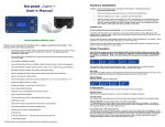
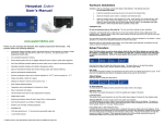
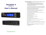
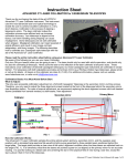
Thank you for choosing the Herpstat II digital proportional thermostat. This product offers the
following features:
Herpstat II
User’s Manual
•
Dual output proportional heating constantly monitors and adjusts amount of heat necessary to
maintain a target temperature (Usable range from 50˚F to 140˚F or 10˚C to 60˚C). Can also be
used in non-proportional (on / off) mode .
•
Second output configurable for Heating / Cooling / or Lighting with simulated sunrise / sunset and
Moonlite feature.
•
Sensor Matching allows the user to digitally calibrate the sensor output to match other equipment.
•
Auto Power Matching constantly adjusts the power output curve to match the enclosures efficiency.
•
Coil Warming feature for enclosures using heating coils to increase accuracy.
•
Night Drop feature built in with real time clock allows individual night drop settings for each output.
Also able to completely turn off the output during the night cycle.
•
Cooling function allows control of basic cooling devices.
•
High / Low temperature tracking helps monitor heating system and enclosure efficiency.
•
Individually selectable High / Low temperature threshold alarms.
•
Precision sensors with internal resolution of .1125 ˚F and is accurate to ± .9 ˚F
•
Display and setting in tenths of a degree.
•
Alarm Clock feature great for daily reminders.
•
All settings are retained in memory even if power is lost.
•
Power Outage detection / tracking.
•
Temperature can be set / displayed in Fahrenheit or Celsius.
•
Easy to read backlit LCD display.
•
Removable sensors allow for easy replacement if necessary.
•
Resettable fuses never require replacement .
•
Each output is fused separately keeping an outage on one output from affecting the other.
•
Audible alarm system
•
Internal error detection shuts off heat if sensor fails or is disconnected.
•
Internal temperature sensor monitors heat and controls internal fan. Also shuts down outputs if
overheated for safety. Restarts automatically once cooled.
•
Device firmware is user upgradeable with optional USB cable.
•
Device status is viewable online with emergency e-mail and vtext alerts (USB cable and software
required).
•
700 Watt rating for each output (1400 watts total output) sufficient for most incubators, rack
systems, enclosures, and vivariums.
•
1 year limited warranty
Data #2
#1
Out#1
Out#2
www.spyderrobotics.com
120
VAC
Hardware Installation
WARNING – FIRE OR ELECTRICAL SHOCK MAY RESULT FROM MISUSE. For INDOOR USE ONLY!
1.
There are 3 connectors on the back of the Herpstat II. From left to right they are Data, PROBE #2,
and PROBE #1. Insert the connector on one of the temperature probes into the PROBE #1 jack. If
heating / cooling two environments insert the second probe into the PROBE #2 jack.
2.
Attach the Herpstat power plug to a standard wall outlet.
3.
There are two output cords on the back of the Herpstat II. The top output cord is the #1 OUTPUT.
Attach the heating / cooling device that PROBE #1 will monitor. . These devices may include heat
tape, heat coils, mats or other resistive load heating devices. Not recommended for use with rock
heating devices or other devices that come in direct contact with the animal. In cooling mode the
outlets can be used for emergency fans. Do not exceed 700 watts per output.
4.
The bottom output cord is the #2 OUTPUT. Attach the heating / cooling that PROBE #2 will monitor
or the lighting device.
5.
The data jack is used with the optional USB cable to upload new programming into the Herpstat
when updates are available or to be used with the optional Herpstat Uploader software that allows
monitoring the Herpstat II status from online and receive Email alerts.
Coil Warmer
Options: ON / OFF
This option is used for incubators that have a coil heating element and is only available in proportional mode. In
testing one of the biggest problems with coil heat elements is the startup time it takes to warm the coil during
regulation. Turning this feature on will keep a small amount of power applied to the coil for a few tenths of a
degree over the target temperature. This limited amount of power usually is not enough to raise the
temperature of the environment but keeps the coil warm so that it can regulate faster once the temperature
drops.
Power Matching
Options: Normal / High1 / High 2 / High 3 / Low1 / Low2 / Low 3 / Auto
This option is only available if the output is set to Proportional Mode. The default setting is Auto. This mode
allows you to adjust the power curve of the Herpstat ND to match the enclosures efficiency and better maintain
the target temperature. Auto will adjust the power curve automatically.
Sensor Matching
This option allows users to match the Herpstat II to other temperature sensing equipment. Use the + and –
buttons to adjust the offset.
Note: The Herpstat II sensors are very accurate in their default setting. Modifications in this menu are not
typically necessary.
NiteDrop Start Time
Configure Menu
Adjustments: Display Type, Output #1 Configuration, Output #2 Configuration,
LiteType, MoonLite, MoonLite Power, Coil Warmer, Power Matching, Sensor Matching,
NiteDrop Start Time, NightDrop End Time, Int Fan, SetClock, Alarm Clock
This is the time the day cycle will end and the night time cycle will begin. This setting affects the Night Drop
temperature and the Lighting option.
NiteDrop End Time
This is the time the night cycle will end and the day cycle will begin. This setting affects the Night Drop
temperature and the Lighting option.
Int Fan
When first powered on the Herpstat II will display the temperature probe status. To enter the Configure Menu
press the + button (this menu only is available from the probe status screen. Use the - button to navigate to it
if necessary). The display will show two options:
+ Setup
- Config
Press the - button to enter the Configure Menu. While in the Configure Menu the Herpstat II will toggle to the
next option after 5 seconds of inactivity and will return to normal operation once all options have been
displayed. While in the Configure Menu all outputs are disabled.
Display Type
Options: Celsius/Fahrenheit
The default setting is to display temperature in Fahrenheit. After changing display modes the target
temperature, night drop amount, temperature thresholds, and the sensor matching setting will be reset to the
default setting.
Output #1 Configuration
Options: Proportional / Non-Proportional / Cooling
The default setting is for Proportional. Proportional mode varies the power output to the heating device as
necessary to maintain the target temperature. Non-proportional works as a standard ON/OFF style thermostat.
Cooling function allows the attachment of emergency fans and functions as a non-proportional output.
Output #2 Configuration
Options: Proportional / Non-Proportional / Cooling / Lighting
The default setting is for Proportional. The second output works exactly as the first output only it includes a
lighting function which is triggered by the NiteDrop start and end times. Modifying this option will reset the
output #2 to it’s defaults.
This option controls the built in cooling fan on the Herpstat II. The default is AUTO which will turn the fan on
and off when necessary. Setting to ON will allow the fan to constantly remain on cooling the Herpstat.
SetClock
Adjusts the internal clock’s time.
Alarm Clock
The alarm clock feature allows the Herpstat II to give a audible beep sequence just like a standard alarm clock.
Pushing either button will stop the alarm.
Setup Menu
Adjustments: Temperature, Night Drop Temp, High / Low Threshold Alarms
When first powered on the Herpstat will display the temperature probe status. To enter the Setup Menu press
the + button (this menu only is available from the probe status screen. Use toggle the – button to navigate to it
if necessary). The display will show two options:
+ Setup
- Config
Press the + button again to enter the Setup Menu. While in the Setup Menu the Herpstat will toggle to the next
setting after 5 seconds of inactivity and will return to normal operation. During the Setup Menu all outputs are
disabled.
LiteType
Day Temp
This is the desired temperature during daytime hours. Default setting is 85˚F or 30˚C. The target temperature
for Output #2 is turned off by default.
Options: Proportional / Non-Proportional
This option becomes available when the Output #2 is set to Lighting mode. When set to Proportional mode and
used with incandescent lighting the Herpstat II will provide a simulated sunrise / sunset that will brighten or dim
the lights in one minute increments over a 10 minute period of time. Non-Proportional mode can be used for
fluorescent lighting. WARNING: Do Not Use Fluorescent Lighting in Proportional Mode!
NiteDrop
This is the amount of degrees you would like to drop during night time hours. For incubators or other
environments that do not require this feature set it to DISABLED. This option is adjustable in tenths of a degree
up to 50.0˚F or 20.0˚C. If set to PWR OFF the output will be completely turned off during the night cycle.
MoonLite
Example: If your day time temperature is set to 88˚F and at night you would like it to drop to 82˚F then you
would set the NiteDrop for that output to 6.0 (88˚F – 6˚F = 82˚F).
Options: ON / OFF
The MoonLite option becomes available when Proportional Mode is chosen for the LiteType. When enabled the
Herpstat II will keep a small amount of light on when dimmed during sunset.
MoonLite Power
Options: Low 3 / Low 2 / Low 1 / Medium / High 1 / High 2 / High 3
This option controls the brightness of the MoonLite. The light will turn on in this menu to allow you to see the
difference in settings. The light will then turn off for remainder of the configuration.
H-Alarm L-Alarm
The temperature threshold alarm feature of the Herpstat II is adjustable from .5 to 10 degrees in tenths of a
degree increments. This feature should not be set until the environment has reached its standard operating
temperature. Once set, if the temperature exceeds or drops below the threshold the Herpstat will sound a
audible alarm and will display a + or – next to the temperature depending on which alarm was breached.
Pressing either button will mute the alarm for 5 minutes. The alarm will still display on the screen.
Example: An incubator set with a standard temperature of 88 degrees, H-Alarm set for .5 degrees and L-Alarm
set for 1 Degree. If the heating coil fails and the temperature reaches 87.5 or below an audible alarm will
sound. Also, should the heat raise to 88.5 or above the audible alert will sound.
Herpstat II Error Code Descriptions
If the night drop option is activated there will be a between time when the environment is changing from the
day temperature to the night temperature or night to day. From the time the NiteDrop is activated or
deactivated the H-Alarm and L-Alarm will be disabled for 15 minutes to allow the environment to stabilize. At
that point they will return to normal operation. If the night drop is set to PWR OFF the alarms will be disabled
during the night cycle.
1=Sensor not present
2=Sensor is shorted
3=Invalid Sensor reading
4=High Temp Alarm breached
5=Low Temp Alarm breached
Tip: Most environments have a degree sway unless it’s a well insulated incubator with a properly set Power
Matching setting. Monitor your environment before using this feature to determine the most realistic setting.
The Display
Options:
Temperature Probe Status / Power Output / High Low Status / Power Outage Monitor
Internal Clock / Internal Temperature
Getting Help
Questions or comments can be e-mailed to:
[email protected]
To purchase accessories please visit us on the web at:
http://www.spyderrobotics.com
Use the – button to toggle between displays. Use the + button to enter a menu or set options.
Temperature Probe Status
Shows the current temperatures from attached probes. By default probe#2 is setup for proportional heat but is
turned off (Display will show #2 OFF). Enable it by entering the SETUP MENU and selecting a target
temperature. When output #2 is set for lighting the status will indicate “#2 Light”. Pressing the + button on
this screen will display the menu options.
Power Output
Displays the amount of power for each output. If Lighting mode is selected for Output #2 then the + button will
manually toggle the lights on and off (or activate MoonLite if configured).
High Low Status
Displays the highest and lowest temperature recorded for that probe. Pressing the + button will reset the
High / Low temperatures to the current temperature for the selected output.
Power Outage Monitor
Each time the Herpstat II is powered on it increments this monitor. To reset the monitor to zero press the +
button.
Internal Clock
Displays the current time and also displays the current day / night cycle determined by the Night Drop
Start / End times.
Optional Accessories
Herpstat Data Cable & Uploader Software
APM (Auto Power Matching)
When the Power Matching mode is set to Auto this screen will be available. Shows the current power matching
mode that the thermostat has switched to. Every three minutes the thermostat will check and adjust this
setting as necessary.
Internal Temperature
Displays the internal temperature of the Herpstat II. The higher the wattage used the higher the temperature
will be.
Getting the most out of your Herpstat II
When setting up a new environment allow a minimum of one hour for the temperature to stabilize. Keep in
mind that all items in the enclosure are warming up including the enclosure walls. Probe placement may require
experimentation to achieve proper temperature regulation.
The Herpstat II has built in resettable fuses. Should it appear that one of the outputs is no longer providing
power unplug the Herpstat II for 2 minutes and then reapply power. This scenario can also happen if the
internal temperature of the Herpstat has reached a high level. The display should show “OverHeat” in this
condition. Also check the cooling fan for normal operation. These tiny fans have high quality ball bearings and
should last a long time. There will be inherent noise from the fan’s operation but it should be comparable to a
standard computer fan.
Do not block the fan vent or impede airflow to the bottom of the Herpstat II. Vent holes on the bottom of the
device provide proper cooling and must not be blocked.
The Herpstat Data Cable plugs into a USB port on computers running Windows 98SE, Windows ME,
Windows 2000, or Windows XP. Features a 12ft cord from the control box and a 6ft USB cable. When used with
the Herpstat Uploader software the Herpstat II will upload its status to the spyderrobotics.com website which
allows users to monitor their equipment from any pc with internet access. Password protection provides
security of user’s information. Features also include emergency e-mail and Vtext messages to Verizon Wireless
phones. Also provides user updateable firmware which means as new software features become available the
Herpstat II device can be reprogrammed without sending it in.
1 Year Limited Warranty
Spyder Robotics warrants this product to be free from defects in workmanship and material for
a period of one year from the date of purchase by the original purchaser. The warranty period
shall not extend beyond 3 years from the date Spyder Robotics shipped the product. During
this warranty period Spyder Robotics will repair or replace, at its option, any component parts
that in its opinion prove to be defective. Replacement parts may be new or serviceable used
parts at Spyder Robotics option, of equal or better quality to those being replaced. This
warranty does not extend and shall not apply to products that have been subjected to misuse,
neglect, accident, or improper installation.
THIS LIMITED WARRANTY AND REMEDY ARE EXCLUSIVE AND EXPRESSLY IN LIEU OF ALL
OTHER WARRANTIES EXPRESSED OR IMPLIED, INCLUDING BUT NOT LIMITED TO ANY IMPLIED
WARRANTIES OF MECHANTABILITY AND FITNESS FOR A PARTICULAR PURPOSE. IN NO EVENT
SHALL SPYDER ROBOTICS BE LIABLE FOR LOST PROFITS, LOSS OF GOODWILL, OR ANY OTHER
INCIDENTAL OR CONSEQUENTIAL DAMAGES.
If you return your product to Spyder Robotics for warranty service, proof of purchase may be
required. A Return Material Authorization (RMA) number must be obtained prior to the return.
Spyder Robotics is not responsible for material returned without the RMA number clearly printed
on the outside of the shipping container. To request an RMA number, contact Spyder Robotics
with the description of failure, serial number of device, and date of purchase via e-mail at
[email protected]. Products to be returned to Spyder Robotics must be returned,
shipping and insurance prepaid, by the original purchaser to the address below.
Spyder Robotics
Attn: RMA# _______
634 S. 1st ST.
Rochelle, IL 61068
©2005 Spyder Robotics
http://www.spyderrobotics.com
manual-HS201
6.29.05