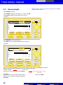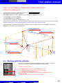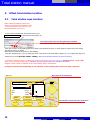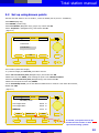
1
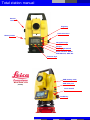
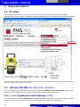
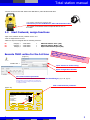
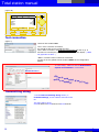
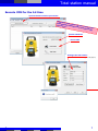
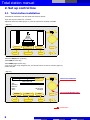
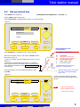
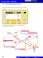
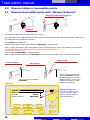
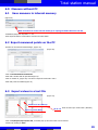
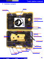
(R100M)
Total station manual
.com
BUILDER 309
Total station manual
Vertical
drive
Page key
Horizontal drive
Battery holder
Navigation keys
Escape
Display light On/Off
Serial interface RS232
USB Abotron, GEV 189
Function keys
USB memory stick
BUILDER 309
(R100M)
USB cable port
Laser On/Off
On/Off key
Total station manual
Table of contents
1. Connection to PC
1.1
1.2
1.2a
1.3
2.
PC setup
Abotron USB cable driver
Constrution Data Manager (CDM)
Start Cadwork, assign functions
Set up control line
2.1
2.2
2.3
2.4
Total station installation
Set up control line
Set up height
Work with the reflector
3. Offset total station location
3.1
3.2
Total station new location
Set up using known points
4. Points layout
4.1
4.2
Export points from Cadwork 3D
Layout stored points on site
5. Measure hidden or inaccessible points
5.1
Measure inaccessible points, with "Measure & Record"
6. Measure without PC
6.1
6.2
6.3
6.4
Save measures in internal memory
Export measured points in PC
Save values in text file
Import points in Cadwork
7. Container contents
3
Total station manual
1. Connection with PC
1.1 PC setup
-On the following website http://www.elcovision.com/e_theoonline.html you will be able to download the software.
-Note that THEO online is necessary to load data in real time in Cadwork 3Dusing the optional Abotron download cable GEV189.
Download
-Send your serial number to [email protected] and you will receive a temporary code valid for 2 days. The software
can be purchased directly on Elcovision's website.
1.2
Abotron GEV189 USB cable driver installation
-Insert the installation CD provided with the cable and folow instructions (USB Download Cable GEV189). Note that the
most current driver can also be found on the Leica Geosystems website in the download area.
1.2a Install Construction Data Manager (CDM)
-Insert the installation DVD (Leica BUILDER series, Instruments CD) and install the Construction Data Manager software.
Note that the most current version can be found on the Leica Geosystems website in the download area.
4
4
Total station manual
-Connect the PC and the total station with USB Abotron, GEV 189 download cable.
Lemo 0/USB = USB Abotron download cable
Connection port for USB Abotron, GEV 189 download cable
-The red dot on the device should correspond with the one on
the cable!
1.3
Start Cadwork, assign functions
-Open a new Cadwork 3D file, Cadwork Version 17.0
-Click on Help\Functions F1-F12
-Make sure keys are assigned with the following functions:
F1
F2
F3
Category =
Category =
Category =
Total station
Total station
Total station
=
=
=
Add total station "Line" (3D)
Add total station "Node" (3D)
Export total station layout (3D)
Execute THEO online for the 1st time
(Figure 7)
Atten
tion:
T
Data
Mana heo online
g e r sh
a
same
ould n nd Leica C
time!
!
o
ot be
execu nstruction
ted at
the
-Double click ->
Open window to format string
Open configuration window
Set communication parameter
as seen in the total station or Construction Data Manager, (Figure 7B, page 6)
Setting should be set only once. Make sure you always plug
the cable to the same port. Doing so will prevent the need to
re-configure the COM #!
Edit communication parameter
(Figure 7A)
CONFIG
THEO
PROG
Laser pointer:
Tracking:
Hz Increment:
V-Setting:
Compensator:
DISP
5
DATA
Off
Off
Right
Zenith
On
COM
TIME
ESC
5
Total station manual
(Figure 7B)
CONFIG
THEO
PROG
Data Output:
Baudrate:
Databits:
Parity:
Endmark:
Stopbits:
DATA
RS232
57600
8
None
CR/LF
1
OK
ESC
Test connection
(Figure 7)
-Check the box besides Laser.
Test 1: Is the connection successful?
You should be able to turn On/Off the laser.
Test 2: Write a number in the field New Point Number and click on (!). If
connection is successful,the point appears on the total station display. ( PROG
tab, application As Built...)
Make 1 of these 2 tests to check the connection!
-In case of an error,please choose another COM # in the configuration
window.
-In Theo config... Make sure the box Mathematical
System of Coordinates is not checked!!
Unchecked box !
If box
is sel
ected
will b
, X an
e ro t a
dYa
ted!!!
xis
Transmitting string
-In the Format Transmitting String window, in
Predefined Strings, choose cadwork and confirm with
OK.
The string will be set to:
XCoord##Enter##YCoord##Enter##ZCoord##Enter
6
6
Total station manual
Execute CDM for the 1st time
Options/Communication parameters
Atten
ti
Data on: Theo o
Mana
nline
ge
a
same
time! r should n nd Leica C
!
o
ot be
execu nstruction
ted at
the
Builder 300 Serie
Serial cable
Settings like total station
or THEO online (Figure 7B, page 9)
Test de connexion
7
7
Total station manual
2. Set up control line
2.1 Total station installation
-Assemble the total station with the tripod and center the bubble
-Press the red power button for 3 seconds.
-Adjust the electronic bubble (Figure 1), once the 3 boxes are checked, press OK.
(Figure 1)
OK
ESC
-Select the DATA menu (Page key)
-Select JOB (Function key)
-Select NEW (Right function key)
-Type a new name using navigation keys; the operator name can also be entered. (Figure 2),
confirm with ok.
(Figure 2)
CONFIG
THEO
PROG
Select next character
DATA
Enter New Job
Job:
Operator:
Remark:
Date:
Time:
Delete
---------------------05.05.2009
14:08:18
OK
123
Scroll Letter/Number/Sign
ESC
Validate data...
8
Total station manual
2.2
Set up control line
(ATTENTION: Select Application -> As Built... !)
-Select PROG menu (Page key)
-Select SETUP, (Right function key)
-Select Control Line... (Navigation keys) (Figure 3), confirm with ok.
(Figure 3)
CONFIG
THEO
PROG
DATA
Control Line ...
Coordinates ...
Height ...
OK
ESC
Arrow represent Y axis
in Cadwork 3d
P1 = Height Z = 0.00 mm
-Select Anywhere... (Navigation keys), confirm with ok.
- Answer NO to message (Record to external ?), (message
P0
P1
P2
P3
a
b
will only apears if the PC and THEO online are connected and
in the THEO online window, the box Use internal memory
is unchecked!)
P1 and P2 define the control line
P1 is set at x0.0/y0.0/z0.0
-Shoot the start point of line P1 and measure M & R (measure
and record). (Figure 4)
-Shoot second point of control line P2 and measure using
key M & C.
Hr = Reflector height
- If laser is not visible, press the middle function key for 3 sec to
activate it.
Total station
Start point of control line
Second point of control line
Point de départ décalé
Offset value for shift
Line value for shift
With the Shift function, the 0 point
of X and Y axis can be changed,
(a+b) = P3.
(Figure 4)
-A value can also be entered to shift the
control line (a and b, above image) to find
point P3.
CONFIG
THEO
PROG
DATA
Measure Line Start Point
Station and Orientation
will be changed and set
Press YES to confirm
M&R
ESC
9
Total station manual
2.3
with this function, point 1 of control line is not at Z=0.0, height is
defined through a measure.
Set up height
-Select SETUP, (Right key)
-Select Height (navigation keys) (Figure 3), confirm with OK.
-Select HTrans, Height transfer (Right key), (Figure 5)
(Figure 5)
CONFIG
THEO
PROG
DATA
Select Height Point
Pt:
E:
N:
H:
----------------.------------.------------.---P-LIST
OK
m
m
m
NEW PT
ESC
-Select NEW PT, New point (Right key)
-Write H01 as the point name (Navigation keys), (Figure 6)
(Figure 6)
CONFIG
THEO
PROG
DATA
Enter Point Coordinates
Pt:
E:
N:
H:
ENH=0
----------------.------------.------------.---OK
m
m
m
ESC
-Scroll to the 3rd line (Navigation keys), in order to enter the True Line height, 1.000 m for example.
Height is entered using the navigation keys, and confirmed with OK.
Validate data !
-Confirm with OK
-Shoot the True Line and measure point (M & R)
Explanation:
In Switzerland, maconry is done using a virtual
height at 1.0m. This virtual height is called the
True Line.
10
New Station Height 1.????m
will be set
Confirm with YES
Total station manual
From now on, Cadwork, THEO Online, CDM, and the total
station are ready to use.
-For the points measured to be transfered to Cadwork, the Use internal memory
box should not be checked! (Figure 7, page 8)
-Select APPL (Right function key) , Application on the total station in PROG menu
-Select As Built... and confirm with OK
-In Cadwork 3D Version 17, press F1 key
-Select a line color (Proceed with available polyline ?) = No
-Now any points can be measured, a line will be drawn in Cadwork point after point with the selectes color. To exit the function,
right click. (Measured points are transfered to the PC through the cable, name of points are kept)
-Before measuring, it's possible to assign a name to the line or node in Cadwork with key (?) and (Enter), traced by the
total station. (It is saved in the user attributes 10)
P1, start point of line
P 1 an
d P2 c
Reference point in Cadwork
+/- 0.00 m
P2, Second point of line
orres
pond
to t
he co
ntrol
li
ne
Z
X
Y
P0, Total station location
+ 1.0 m
PT0001
2.4 Working with the reflector
-In a case of a point that can be hardly measured, the use of a reflector is necessary.
-To do this, the reflector height should be adapted hr=Reflector height
hr = 100mm, 0.1m
-To adapt the reflector height:
1. Select SETUP (Right function key), in the PROG menu
2. Select Height (Navigation keys) (Figure 3), confirm with OK.
3. Select hr, reflector heigh (Navigation keys)
4. Type value 0.1 m (or depending on the configuration: 0.4, 0.7, 1.0, 1.3 m))
5. Confirm with OK
6.You now see the chosen height, confirm again with OK.
11
Total station manual
3. Offset total station location
3.1
Total station new location
When measuring buildings (interior and
exterior) the total station should be moved
on several occasions. How to do this? The
following describes how to do it.
-To save points assciated with the internal memory, the
Use internal memory box should be checked! (Figure 8)
(Figure 8)
The name of the point can be typed here and then
be sent to the total station using the (!) button
-Now mark 2 points on the building (Reference points) using positionning items (or while doing the layout during the raising),
and make sure they are visible.
Write also the names of the points on the building !
-Using the navigation keys, you can modify the name of the points on the total station, (Figure 9), or on THEO online (Figure 8)
-Measure the 2 points (Example. V0001 - V0002). (Both points should be saved in the internal memory)
-To load the 2 reference points in Cadwork also called security points, press F2 on the PC to Add total station "node" (3D),
select a color and measur points again. (Attention; The Use internal memory box should be unchecked)
Assign the same names in Cadwork 3D as in the building and the total station!
It highly recommended, depending on the situation of the building site to use more than 2 points!!!!
Next point to be measured
(Figure 9)
CONFIG
THEO
PROG
DATA
As Built
Pt:
PT0004
Line:
Offs:
H:
APPL
6.137
1.474
2.075
m
m
m
M&R
SETUP
ESC
Coordinates of the last point measured
12
Total station manual
3.2 Set up using known points
-Relocate the total station to its new location , center the bubble (Like in point 2.1: Installation)
-Select PROG (Page key)
-Select SETUP, (Function key)
-Select Coordinates (Navigation keys), (Figure 10) confirm with OK
-Select Anywhere... (Navigation keys), and confirm with OK
(Figure 10)
CONFIG
THEO
PROG
DATA
Control line ...
Coordinates ...
Height ...
OK
ESC
-Do not edit hi (Instrument height).
-hr (=reflector height) see Point 2.4, press ok to continue.
-Select the 1st reference point (Navigation keys) and confirm with OK.
-Measure the 1st point! V0001, while shooting the point on the reference surface.
-Select the second reference point (Navigationkeys) and confirm with OK
-Measure the 2nd point the same way: V0002
-On the Plausibility Check, you see the difference between the 2 measures. If its within the tolerance,
validate with YES.
(Figure 11)
CONFIG
THEO
PROG
DATA
Vérifier les Check
Plausibility
résultats
Line length Given:
6.506
m
Line length Meas.:
6.506
m
Difference
0.000
m
NO
NEXT PT
YES
ESC
If needed, a 3rd point can also be
measured. The location is then
reprocessed using 3 points
13
Total station manual
3.2
Set up using known points
-Station and Orientation StatAny-002 will be changed and set! Confirm with YES.
(Figure 12)
CONFIG
THEO
PROG
DATA
New station coordinates
Station:
StatAny-002
E:
2.698
m
N:
1.119
m
H:
1.443
m
NO
YES
ESC
-New coordinates of the station are displayed, confirm with YES. (Figure 12)
-The total station is ready to measure.
P1, start point of line
REF.PT
S002
P1 an
d
P2, Second point of line
P2 co
rr
espon
d to t
h e co
ntrol
lin
e
REF.PT
S003
Reference point in Cadwork
+/- 0.00 m
Z
X
Y
P0, First instrument location
before relocation
+ 1.0 m
PT0001
Second instrument location
after relocation
14
Total station manual
4. Points layout
4.1
Export points from Cadwork 3D
-In Cadwork 3D, Version 17, assign F3 key to function: Total station\Export total station layout (3D)
-Now press F3 (Export total station layout (3D))
-Type a file name for the new list of nodes in the window that pops up (ex: AS 1) and choose a location where to save it.
(Default location is the current folder)
-Select a color to export nodes.
-Type a starting number for the nodes numbering (ex: migg2))
-In 3D select all points that have to be exported using the left click, exit the function by right click
-A text file apears (......txt) on the display, see figure 13
(Figure 13)
-Once the text file is open, it can be edited and modified (ex: Nodes number)
-double click -> Execute Construction Data Manager (CDM), Figure 14
Coordinates order East/North
-In CDM, click on Options/Settings.. and make sure values for
coordinates and units are set the same as in Cadwork.
Coordinates: East/North (X/Y) and unit: metre!
Metre
(Figure 14)
To import the text file data, click on
Import/TXT-File and select your file.
15
Total station manual
-Send data using the Upload to instrument button
-In the Pick up a Job... , type a New Job name (Figure 15)
(Figure 15)
-Click on OK
4.2
Layout stored points on site
-Select DATA with the Page key and select the imported JOB with the navigation Keys.
-Set up the total station, bubble and location thanks toreference points (description in point 3.2)
(Note that reference points can be saved as a different Job!)
- It is also possible that reference points are concrete slab corners, which are also represented in the cadwork 3D file and
available on site.
-Select PROG using the Page key, then with the function key APPL. and navigation key Layout..., press OK.
Using navigation keys, select the point you wish to trace.
(Figure 16)
CONFIG
THEO
PROG
Layout
Pt:
PT0004
Line:
Offs:
H:
APPL
6.137
1.474
2.075
Rotation direction
DATA
Turn
Builder
m
m
m
5.220 m
050°30'31"
0.725 m
MEASURE
SETUP
ESC
-Using the vertical and horizontal drive, adjust the total station precisely.
-Once the instrument is on target, press the middle function key MEASURE
-If the value is slightly off, reposition until you get a result within an allowed tolerance.
16
Distance with the point
Accurate rotation angle
Value for the height
Total station manual
4.2
Layout stored points on site
-The result of the traced points can only be accurate if the total station measures constantly and that parameters
(Reference points) are accurate also.
-Set, like described in figure 17, in CONFIG, the Laser Pointer and Tracking functions on ON.
-Once tracking is turned on, the total station measures in real time and displays the Rotation / Distance /
Height values
(Figure 17)
Turn on laser
Turn on tracking
CONFIG
THEO
PROG
Laser Pointer:
DATA
On
On
Tracking:
Horizon
Hz Increment:
Zenith
V-Setting:
On
Compensator:
OK
ESC
Turn on compensator
4.3
Transfer a list of points using the USB stick
- Once data are imported in "Construction Data Manager ", as described in 4.1, they will be directly exported. However,
the export function will not be used but rather the Save As... function in the File menu. The file format to select is *.GSI
and data should be saved on the USB stick in a sub-folder called "DATA".
- Once the USB stick is plugged to the total station, the job can be read in the instrument. To access data, select DATA
(Page key) then press the left function key IMP/EXP, select the file to import nd once imported, the layout can start.
17
Total station manual
5.0
Measure hidden or inaccessible points
5.1
Measure inaccessible points with "Measure & Record"
Adaptation of the angle on the side
Dista
nce
Obstacle
-Combination of MEASURE and RECORD step by step:
The combination of keys Measure & Record can be used, with the reflector for points that are inaccessible. When a corner
of a building has to be measured for instance.
-Select PROG with the Page key.
-Parameters should be: Config <Measure&Record: MEAS/REC> (See figure 18)
-Step 1, position the reflector at the same distance from the instrument as the corner of the building to be measured.
(The distance from the total station to the corner of the building should however
be the same to the reflector!)
-Press function key MEASURE, to measure distance.
-Step 2, adjust the angle and save it with RECORD. The saved result is a distance (Step 1) and the angle (Step 2).
Adjust height
Corner unavilable
Adjust angle
-Step 2, shoot the virtual point
and press RECORD, this way,
the distance (Step 1) and the
direction (Step 2) will be sent to
Cadwork or saved in the total
station internal memory.
nce
Dista
-Step 1, measure the distance
(MEASURE).
(Figure 18)
CONFIG
THEO
PROG
Off
Beep:
Auto Off:
Enable
Measure & Record:
MEAS/REC
OK
18
Normal setting = ALL,
To measure hidden points:
Step 1 = distance, Step 2 =
direction,(height+rotation)
Set on MEAS/REC.
DATA
ESC
Total station manual
6.0 Measure without PC
6.1
Save measure in internal memory
(Figure 19)
Make all measures in the internal memory! Or unplug the USB cable from the PC
-Installation/Setup look at points 2.1 - 2.3
-Now all points that are measured are stored in the total station
6.2 Export measured points on the PC
-Execute the Construction Data Manager, (Figure 20)
(Figure 20)
-Click on Download from instrument
-Wait until a window with all jobs stored pops up.
-Click on number 61, (Figure 20) in order to load points measured in Job 9.
-Wait until points are loaded (Figure 21)
6.3 Export values in a text file
(Figure 21)
Value on Y axis (North)
Value on X axis (East)
No X Y Z Order of values (For nodes name / Number)
-Click on Im/Export/Export/TXT-File, a window pops up and a file name can be entered.
Continue by clicking on Save.
19
Total station manual
6.4
Import points in Cadwork
-Open a cadwork 2d file
-Add/File.../Terrain points.../No X Y Z
-Add/Node.../Global coord. and enter values X=0, Y=0, Z=0
to obtain Point-0 (Origine).
-Activate the node Point-0 with a left click and select all nodes to be exported with a right click lasso.
-Now press ',' (Comma) in Cadwork 2d, (To write a clipboard for the 3D) and assign a number.
-Open a Cadwork 3d file and paste '3' all points.
20
Total station manual
Notes:
21
Total station manual
22
Total station manual
7. Container contents
Reflector
Clip-on bubble
for reflector
Protective cover
lens hood
USB cable
Connection cable total station-PC
Lemo 0/USB =
Abotron USB Download Cable
GEV 189 (optional)
Builder user manual
How to guide
Installation DVD
30 cm rods
for reflector
4 elements
12 Volt Car charger
cable
Targets
Battery charger adapter
Spare battery (optional)
Charger cable
Battery charger
Battery
Adjusment tools
Tip for reflector pole
23
.com