1
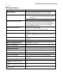
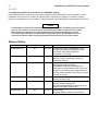
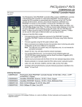
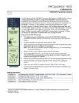
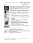
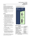
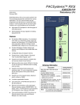
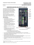
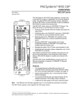
PACSystems* RX3i IC695PNC001-AF PROFINET Controller Module GFK-2573F August 2013 * 1 OK 2 LAN 3 STATUS 4 CONFIG The PACSystems RX3i PROFINET Controller (PNC) module, IC695PNC001, connects a PACSystems RX3i controller to a high-speed PROFINET local area network. It enables the RX3i controller to communicate with IO-Devices on the LAN. The PNC provides all the functions, services, and protocols required for certification as a PROFINET IO Version 2.2 IO Controller, running at both 100 Mbps and 1 Gbps. PNC001 TO INSTALL, TORQUE TO 6 IN-LB. TO UNINSTALL, REVERSE MOTION The PNC supports 10/100/1000 Mbps Copper, 100/1000 Mbps Multi-mode Fiber, and 100/1000 Mbps Single-mode Fiber. The LAN can include media interfaces of more than one type. PROFINET communications on the LAN require 100 and 1000 Mbps link speed. 10 Mbps cannot be used for PROFINET communications. However, 10 Mbps can be used for other types of Ethernet traffic such as ping and telnet. Features of the RX3i PNC include: ACTIVE ▪ Full programming and configuration services for the PROFINET Controller, VersaMax PROFINET Scanner and third-party IO-Devices using Proficy Machine Edition. ▪ ▪ Firmware upgrades using the WinLoader software utility. USB USB RESTART ! IP ADDRESS INTERFACE MAC PORTS ▪ ▪ Support for star, ring, and daisy-chain/line network topologies. ▪ ▪ ▪ ▪ Internal clock synchronized with the RX3i CPU for time-stamped diagnostics entries. FRONT 3 4 1 2 Built-in Command Line Interface function that provides direct monitoring and partial configuration via the micro USB port or using telnet. Note: The USB port is for system setup and diagnostics only. It is not intended for permanent connection. Four switched Ethernet ports - two 8-conductor RJ-45 shielded twisted pair 10/100/1000 Mbps copper interfaces and two Small Form-factor Pluggable (SFP) cages for user-supplied SFP devices. Restart pushbutton to manually restart the PNC without power cycling the system. LEDs: OK, LAN, STATUS, CONFIG, ACTIVE, USB, and four Port LEDs. Compliant with EU RoHS Directive using the following exemptions identified in the Annex: 7c-I and 7c-III. Ordering Information IC695PNC001 * IC200PNS001 PACSystems RX3i PROFINET Controller Module 10/100/1000, 4 Ports - 2 SFP connections, 2 Copper VersaMax PROFINET Scanner, 10/100, 2 Ports, Copper IC200PNS002 IC695SPC100 IC695SPF002 VersaMax PROFINET Scanner, 10/100, 2 Ports, Multimode Fiber RX3i 10/100/1000base-TX (CAT5 100m) SFP RX3i 100Base-FX (fiber 2 km) SFP Indicates a trademark of GE Intelligent Platforms, Inc. and/or its affiliates. All other trademarks are the property of their respective owners. 2 IC695PNC001-AF PROFINET Controller Module GFK-2573F PNC Specifications PROFINET Support PROFINET Version 2.2 General Class A IO-Controller CPU Compatibility CPU315 or CPU320, with firmware version 7.0 or higher CPE305/CPE310 with firmware version 7.10 or higher Power Requirements 3.3 V: 0.5 A with no SFP devices installed 1.2 A maximum (two SFP devices installed, 0.35 A per SFP device) 5 V: 1.5 A maximum Operating Temperature Range 0 to 60°C maximum surrounding air temperature without a fan. A lower maximum temperature may be required depending on PNC location and SFP population. Refer to “Operating Range for Air Temperature” in the PACSystems RX3i PROFINET Controller Manual, GFK-2571. Number of Port Connectors Two RJ-45 and two SFP Cages (SFP devices not included, available separately) Micro USB Connector One, for communication with a computer using Command Line Interface. LAN IEEE 802.2 Logical Link Control Class I IEEE 802.3 CSMA/CD Medium Access Control 10/100/1000 Mbps Maximum I/O Memory 128 Kbytes of combined input/output memory per PROFINET Controller CPU Status Bits 32 PROFINET I/O Device Data Update Rates on the PROFINET LAN Configurable: 1 ms, 2 ms, 4 ms, 8 ms, 16 ms, 32 ms, 64 ms, 128 ms, 256 ms and 512 ms Number of IP addresses One Number of MAC Addresses Five. One per external port and one internal. System Maximum Limits PNCs per RX3i CPU 4. Must be located in main rack. Cannot be located in a remote node. IO-Devices per IO-Controller 64 per PROFINET Controller IO-Devices per Network 255 per network, spread across up to 8 IO-Controllers IO-Devices per RX3i CPU 255 per RX3i CPU, spread across up to 4 PROFINET Controllers IO-Controllers per network 8 Number of PROFINET Slots per device Number of PROFINET Subslots per slot Number of PROFINET Submodules per RX3i CPU 256 256 2048 IC695PNC001-AF PROFINET Controller Module 3 GFK-2573F PNC Specifications, continued Programmer Limits Number of IO-Controllers 128 (32 RX3i CPU targets × 4 IO-Controllers per RX3i CPU) Number of IO-Devices 4080 (255 per network × 16 PROFINET networks) Total number of devices 4208 (does not include backplanes, power supplies, or IO modules) Hot-swappable Yes For product standards, general operating specifications, and installation requirements, refer to the PACSystems RX3i System Manual, GFK-2314. References For additional information, please refer to the manuals listed below. Manuals can be downloaded from the Support website, http://support.ge-ip.com. PACSystems RX3i PROFINET Controller Manual, GFK-2571A PACSystems RX3i PROFINET Controller Command Line Interface Manual, GFK-2572 VersaMax PROFINET Scanner User’s Manual, GFK-2721 PACSystems CPU Reference Manual, GFK-2222 PACSystems RX3i System Manual, GFK-2314 EMC Installation Requirements To meet EN 55011 and FCC Class A radiated emissions, the Control system in which the IC695PNC001 module is used shall be mounted in a metal enclosure when three or more IC695PNC001 modules are used. All surfaces of the enclosure must be adequately grounded to adjacent surfaces to provide electrical conductivity. Wiring external to the enclosure must be routed in metal conduit or the equivalent. The conduit must be mounted to the enclosure using standard procedures and hardware to ensure electrical conductivity between the enclosure and conduit. When installing, operating, or maintaining the IC695PNC001, personnel must insure any electrostatic charge is discharged through the use of a grounded ESD strap or other means. Installation in Hazardous Areas The following information is for products bearing the UL marking for Hazardous Locations or ATEX marking for explosive atmospheres: EQUIPMENT LABELED WITH REFERENCE TO CLASS I, GROUPS A, B, C & D, DIV. 2 HAZARDOUS LOCATIONS IS SUITABLE FOR USE IN CLASS I, DIVISION 2, GROUPS A, B, C, D OR NON-HAZARDOUS LOCATIONS ONLY WARNING - EXPLOSION HAZARD - SUBSTITUTION OF COMPONENTS MAY IMPAIR SUITABILITY FOR CLASS I, DIVISION 2; WARNING - EXPLOSION HAZARD - WHEN IN HAZARDOUS LOCATIONS, TURN OFF POWER BEFORE REPLACING OR WIRING MODULES; AND WARNING - EXPLOSION HAZARD - DO NOT CONNECT OR DISCONNECT EQUIPMENT UNLESS POWER HAS BEEN SWITCHED OFF OR THE AREA IS KNOWN TO BE NONHAZARDOUS. WARNING - EXPLOSION HAZARD - USB PORT IS ONLY FOR USE IN NONHAZARDOUS LOCATIONS, DO NOT USE UNLESS AREA IS KNOWN TO BE NON-HAZARDOUS. ATEX Marking II 3 G Ex nA IIC T5 X Ta: 0 - 60C 4 IC695PNC001-AF PROFINET Controller Module GFK-2573F Status Reporting The PNC provides 32 bits of status information to a configured location in the RX3i CPU’s reference memory. The status data consists of the Module OK bit, which indicates the health of the module itself, a status bit for each external port, and a bit that indicates the connection status of the configured devices. All Status bits are active high. The status location may be configured in %I, %Q, %AI, %AQ, %R, %G, %T, %M or %W or I/O Variable reference memory in the RX3i CPU. Bit Name 1 Module OK Description Indicates the health of the PNC module. 1 indicates the module is functioning properly. 0 indicates the module is powering up or has failed. 2 Port1 Link Up 1 indicates the port is connected to another device and is operating correctly. Port2 Link Up 0 indicates the port is not connected to another device or the port has an error Port3 Link Up preventing communications, or the SFP cage is empty or has an incompatible SFP device. Port4 Link Up 3 4 5 6-8 9 10-32 * Reserved Reserved. Always 0. All Devices Connected* 1 indicates all configured devices are connected and communicating over PROFINET. 0 indicates no devices are configured or one or more configured devices have not established a PROFINET connection. Reserved Set to 0 Individual device statuses (as reported by the PNIO_DEV_COMM function block) are updated prior to the All Devices Connected bit. Therefore, it is possible (depending on PNC loading) to see via the PNIO_DEV_COMM function block that every individual device is connected while the All Devices Connected bit is not yet set. To avoid this inconsistency, it is recommended that the All Devices Connected bit be checked first, before checking individual device connection status using the PNIO_DEV_COMM function block. For details on using the PNIO_DEV_COMM function block, refer to “RX3i CPU Operations for PROFINET” GFK-2571. LEDs on the PROFINET Controller Module The table below summarizes LED functions. For detailed information about error indications and special blink patterns refer to Installation and Diagnostics in GFK-2571. OK Indicates whether the module is able to perform normal operation. LAN Indicates network packets are being processed by the network interface (not just passing through the embedded switch). STATUS Indicates the condition of the PROFINET Controller during normal operation. It indicates whether an entry other than the startup event is present in the module’s local log. STATUS can also indicate whether any of the MAC addresses are invalid. Indicates whether the module has received its configuration from the RX3i CPU. CONFIG ACTIVE USB Port LEDs Indicates the status of PROFINET connections. Indicates activity on the USB port. Indicate link speed, link connection and link activity corresponding to the four possible external Ethernet ports. IC695PNC001-AF PROFINET Controller Module 5 GFK-2573F Quick Start Installation and initial startup procedures for the PNC include the following steps. Before installing and operating the PNC, refer to the PACSystems RX3i PROFINET Controller Manual, GFK-2571 for detailed information. 1. Pre-Installation check 2. Installing the PNC in an RX3i backplane The PNC must be installed in the main (CPU) rack of the RX3i system, using a Universal Backplane such as IC695CHS007, CHS012 or CHS016. The PNC supports insertion/removal while power is applied to the system (hot swap). This includes backplane power and field power supplied to the PNC. The back of the PNC has an exposed heat sink and backplane connector. Before inserting the module into the backplane, remove the plastic knockout in the slot where the module will be placed. The installation slot must match the slot that is selected in the module’s hardware configuration. Warning Inserting or removing a PNC with power applied to the system may cause an electrical arc. This can result in unexpected and potentially dangerous action by field devices. Arcing is an explosion risk in hazardous locations. Be sure that the area is non-hazardous or remove system power appropriately before removing or inserting a PNC. 3. Connecting the PNC to the PROFINET network and to a 10BaseT, 100BaseTX or 1000BaseT IEEE 802.3 network for general Ethernet communications Caution Do not connect two or more ports on the PNC to the same device, either directly or indirectly, unless Media Redundancy is enabled in the PNC’s configuration. If Media Redundancy will be used, do not close the network ring until after the Media Redundancy configuration which contains one node as a Media Redundancy Manager (MRM) has been downloaded to the PNC. If a Media Redundancy Manager is not present, packets can continuously cycle on the network, using up significant network bandwidth. Note: Shielded cable is required for 1 Gbps operation. 4. Installing SFP devices Warning Optical SFPs use an invisible laser to generate a fiber-optic signal. Always keep the port covered if a cable is not installed. Do not look into the open port if a cable is not installed. Warning If the surrounding air operating temperature of the PNC is greater than 40 C,SFP devices could have operating temperatures over 70 °C (158 °F). Under these conditions, for your safety, do not use bare hands to remove an SFP device from the SFP cage. Use protective gloves or a tool (needle-nose pliers) to avoid handling the hot SFP device directly when removing the SFP device. 5. Installing the USB port driver (optional) The PNC provides a micro USB port for connection to a computer running Windows 2000, Windows XP, Windows Vista, or Windows 7 operating system. The computer can access the PNC’s Command Line Interface function using a terminal application such as Hyperterm. The PNC is provided with a driver-install application that can be used to enable a computer to communicate with a PNC via its USB port. For details on using the Command Line Interface, refer to the Command Line Interface Manual, GFK-2572. 6 IC695PNC001-AF PROFINET Controller Module GFK-2573F 6. Configuring the PNC and its IO Devices on a PROFINET network Proficy Machine Edition is the primary tool used to configure an RX3i PROFINET network. In addition, certain parameters can be set from a computer through the PNC’s Command Line Interface. For details on system planning and configuration, refer to chapter 3 of the PACSystems RX3i PROFINET Controller Manual, GFK-2571. Caution If an RX3i PNC is extracted from a powered RX3i backplane, it loses power immediately which may result in data loss. Do not remove or insert the device while downloading hardware configuration to the system. When the PNC is plugged back into a powered backplane, the PNC restores data from the internal non-volatile memory. If however, the RX3i CPU has configuration data for the PROFINET Controller, it re-delivers the data to the PNC, superseding parameters previously stored in non-volatile memory. Release History Firmware Revision Date Comments IC695PNC001-AF 1.23 Aug. 2013 IC695PNC001-AE 1.22 Jul. 2013 IC695PNC001-AD 1.21 Jul. 2012 IC695PNC001-AC 1.20 Mar. 2012 IC695PNC001-AB 1.10 Dec. 2011 IC695PNC001-AA 1.00 Jun. 2011 Corrects issue storing a PROFINET device configuration greater than 64K bytes in size. For details, see Problems Resolved in Release 1.23 on page 7. Corrects an issue where, in some configurations, the PNC entered a mode that caused it to repeatedly power up. This release addresses a power up issue affecting the following revisions IC695PNC001-AB and IC695PNC001-AC. Although no units that exhibited this issue were shipped, it is recommended to update firmware to prevent the possibility of encountering a power up issue in the field. Adds support for up to 255 PROFINET IO Devices per RX3i CPU. Adds support for SNMP and LLDP standards to facilitate network management. Provides enhanced Revision Information in the Explore PROFINET Networks tool. Initial release. Supports GSDML Version 2.2 and previous. Version IC695PNC001-AF PROFINET Controller Module 7 GFK-2573F Important Product Information for this Release Upgrades The PNC can be field upgraded to firmware version 1.23 using the Winloader firmware upgrade utility and upgrade kit 82A1790-MS10-000-A5, which can be downloaded from http://support.ge-ip.com. Compatibility The following CPU firmware, programming software and backplane hardware versions are required to use the features introduced in PNC release 1.20 and later: RX3i CPU firmware Programmer software VersaMax PROFINET Scanner RX3i backplane hardware CPU315/CPU320 with firmware version 7.10 or later CPE305/CPE310 with firmware version 7.10 or later Proficy Machine Edition version 7.0 SIM 8 or later IC200PNS001/002 with firmware version 1.00 or later The following backplane hardware revisions must be used: IC695CHS012-BAMP IC695CHS016-BAMP IC695CHS012CA-BAMP IC695CHS016CA-BAMP or IC695CHS012-CA (or later) IC695CHS016-CA (or later) IC695CHS012CA-CA (or later) IC695CHS016CA-CA (or later) or IC695CHS007-AA (or later) Problems Resolved in Release 1.23 Subject PROFINET Device Configuration limited to 64K Description Attempts to store a configuration to the PNC which contains a PROFINET device configuration that exceeds 64K bytes resulted in an IOC Software Fault – Module Firmware Fault. This fault then resulted in storing PLC going to STOP/FAULTED state. PNC firmware version 1.23 corrects the problem so that a PROFINET Device configuration greater than 64K bytes can now be stored successfully. 8 IC695PNC001-AF PROFINET Controller Module GFK-2573F Restrictions and Open Issues Restrictions and Open Issues related to PNC Operational Behavior Subject Electrostatic Discharge induced upset Radiated Emissions when using three or more IC695PNC001 units. Unintended LED blink pattern Unexpected Loss of Device faults Unintended operation of PNIO_DEV_COMM function block IOC SW Fault with large configurations Description For installation requirements, see the section “EMC Installation Requirements” on page 3. When an overtemperature condition occurs, the PNC001 will blink this pattern: PORT 1, PORT 2, and STATUS LEDs on red for 0.5 seconds (all other LEDs off), then PORT 3 and PORT 4 LEDs on red for 0.5 seconds (all other LEDs off). This is not the correct pattern, as documented in the PACSystems RX3i PROFINET Controller Manual (GFK-2571). Loss of Device faults for currently connected devices may appear in the PLC I/O Fault table and/or PNC local log when the PNC is reset via its reset pushbutton. The power flow output of the PNIO_DEV_COMM function block provides validation of the input parameters and confirms that the PNC has locally processed the configuration of the specified I/O Device. As currently implemented, the power flow output will not turn ON until after the PNC has made its first attempt to connect to the specified I/O Device. Therefore, we recommend the user not rely on power flow output for parameter validation. When storing a configuration to the PNC that is close to the upper limit of the controlling PLC’s user memory, the store may fail with an IOC SW Fault logged in the PLC’s I/O Fault table. The work-around to resolve this issue is to clear the PLC’s existing configuration and store the configuration again. Restrictions and Open Issues related to the Command Line Interface Subject Description Page function not available Response to invalid command entry The output paging function, as described in the shConfig command, is not currently functioning. The error message displayed in response to an invalid show port help command does not provide useful information. Example: show port fdp help is an invalid command. To see a list of valid parameters for the show port command, type show port ? "telnetd" command response The CLI does not echo the new number of max connections in its response to the telnetd <maxconnections> command. However, the command still functions properly, and updates the maximum number of telnet connections. When displaying numerous local log table entries using the log details command, sometimes erroneous blank characters appear within the display. Use the log details <log entry number> command to view the disrupted log table entry. Example: log details 99. "log details" command response "term" command response Occasionally, the CLI does not respond to the "term" command. To recover, restart the terminal emulation program. IC695PNC001-AF PROFINET Controller Module 9 GFK-2573F Operational Notes Subject Description Ring network configuration and parameter considerations for bumpless PROFINET IO Device operation with Media Redundancy Protocol (MRP) Use of the Media Redundancy Protocol (MRP) allows a user’s ring network to automatically heal itself in the event of a single break of the ring network. If a user’s application requires the PROFINET IO Devices to operate bumplessly through ring network recovery (no observed loss and subsequent addition of PROFINET IO Devices while the ring network recovers), the following network and application design guidelines must be observed: 1. If only one PNC is in the ring acting as the Media Redundancy Manager (MRM) and all of the Media Redundancy Clients (MRCs) are VersaMax PROFINET Scanners, customers can set minimum IO Update Rates as follows and expect PROFINET IO to operate bumplessly through ring network recovery: ▪ Using the fixed copper ring ports on the PNC, 1 ms IO Update Rate minimum ▪ Using SFPs on the PNC, 4 ms IO Update Rate minimum 2. If multiple PNCs are in the ring (one PNC acting as the MRM and other PNC(s) as MRC(s)) where VersaMax PROFINET Scanners are the only PROFINET IO Devices, customers can set minimum IO Update Rates as follows and expect IO to operate bumplessly through ring network recovery: ▪ 16 ms IO Update Rate minimum, regardless of ports utilized, and must set MRP Test Packet Interval to 10 ms and MRP Test Packet Count to 2. 3. If 3rd party MRCs are in use in the ring, customers can set a minimum IO update rate to the larger of the options that follow and expect IO to operate bumplessly through ring network recovery: ▪ Minimum IO Update Rate configurable in PME that is at least 1/3 the time of the worst-case ring recovery stated by 3rd party manufacturer, regardless of ports utilized. (i.e. if a manufacturer states their worst-case ring recovery is 90 ms, then the minimum IO update rate allowed would be 90/3 = 30 ms ~ 32ms.) or ▪ 16 ms IO Update Rate minimum, regardless of ports utilized, and must set MRP Test Packet Interval to 10 ms and MRP Test Packet Count to 2. 10 IC695PNC001-AF PROFINET Controller Module GFK-2573F Subject Description Storing updated media redundancy protocol (MRP) configurations to large operating MRP ring networks with fast IO update rates configured can result in PROFINET IO device Loss/Add faults When storing Media Redundancy Protocol (MRP) configuration updates to an operating MRP ring network, users may infrequently observe one or more pairs of “Loss of Device” and subsequent ”Addition of Device” faults regarding PROFINET IO Device faults on the network. This is expected behavior and is more likely to occur on ring networks with a large number of PROFINET IO Devices acting as MRCs with very fast IO Update Rates configured. Because changing MRP configuration settings requires each MRC to break and reconnect its own connections to the ring network, IP packets on the network may be lost as this flurry of connection breaks/ reconnects occur on the network. Since a PROFINET IO Device is considered lost if it misses three consecutive IO data transactions, if three consecutive IO data packets from a particular PROFINET IO Device are lost due to network reconfiguration, the device will appear to be lost to the PNC and a Loss of IO Device is logged. When the network stabilizes, the PNC will be able to reestablish connection with the lost IO Device and an Addition of IO Device fault will be logged. Data packets arriving on ports blocked by Media Redundancy Protocol (MRP) still forwarded over mirrored ports When a network is configured for MRP operation, MRCs and Media Redundancy Managers (MRMs) can put one of their ring ports into a “Blocking” state. MRP uses this blocked port state to break the continuous ring and allow only MRP management traffic to pass through the blocked port. All of the non-MRP management traffic is blocked from ingress or egress of the blocked port. If the port has been set up using the port mirroring “monport” command, to monitor traffic on the blocked port, all of the traffic that arrives at the blocked port is mirrored to the configured monitor port regardless of whether or not the traffic is MRP management traffic. This makes it appear that the traffic is being sent or received on the blocked port even though it is not. Network monitoring devices should be directly connected to mirrored PNC ports When using the port mirroring “monport” command to monitor Ethernet traffic, you should directly connect your PC/Laptop to the port on the PNC that is monitoring the traffic. If there is an intervening switch in the mirrored path, the mirrored traffic will corrupt the intervening switch’s routing table. A corrupted routing table can cause dropped Ethernet packets, resulting in the loss of PROFINET IO and/or other Ethernet communication. PROFINET IO Device Loss/Add Faults for 3rd party IO devices may occur on hardware configuration store in some large network configurations When storing hardware configurations with more than 64 PROFINET IO Devices that include multiple PNC modules and 3rd party PROFINET IO Devices on a single network, occasional Loss/Addition of IO Device faults may be logged for some 3rd Party PROFINET IO devices. The devices should operate normally after being re-acquired by their controlling PNC module. The Loss/Addition faults can be disregarded.