1
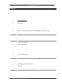
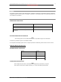
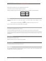
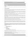
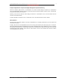
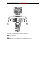
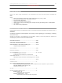
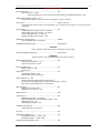
‘767 Captain’ Sim FLIGHT MANUAL Part III – Normal Procedures
DO NOT USE FOR FLIGHT
‘767 Captain’
FLIGHT MANUAL
PART III – Normal Procedures
Captain Sim is not affiliated with any entity mentioned or pictured in this document.
All trademarks are the property of their respective owners.
© 2009 Captain Sim www.captainsim.com
1
‘767 Captain’ Sim FLIGHT MANUAL Part III – Normal Procedures
DO NOT USE FOR FLIGHT
ABOUT THIS MANUAL
VERSION: 23 JULY, 2009
WARNING: THIS MANUAL IS DESIGNED FOR MICROSOFT® FSX USE ONLY. DO NOT USE FOR FLIGHT.
The ‘767 Captain’ FLIGHT MANUAL is organized into five Parts:
Each Part is provided as a separate Acrobat® PDF document:
Click START > Programs > Captain Sim > 767 Captain >
•
Part I – User’s Manual
•
Part II – Aircraft Systems
•
Part III – Normal Procedures - this document
•
Part IV – Flight Characteristics and Performance Data
•
Part V - Flight Management System.
Adobe Acrobat® Reader Required
FOR GENERAL INFORMATION ON THE ‘767 CAPTAIN’ PRODUCT PLEASE USE WWW.CAPTAINSIM.COM .
THIS MANUAL PROVIDES ADDITIONAL INFORMATION ONLY, WHICH IS NOT AVAILABLE ON THE WEB SITE.
© 2009 Captain Sim www.captainsim.com
2
‘767 Captain’ Sim FLIGHT MANUAL Part III – Normal Procedures
DO NOT USE FOR FLIGHT
CONTENTS
Page
4
4
4
4
4
4
5
5
5
5
5
5
OPERATING LIMITATIONS
GENERAL
AIRPLANE GENERAL
OPERATIONAL LIMITATIONS
NON-AFM OPERATIONAL INFORMATION
AIRPLANE WEIGHT RESTRICTIONS
AUTO FLIGHT
ENGINE
ENGINE FUEL SYSTEM
REVERSE THRUST
FLIGHT CONTROLS
NAVIGATION
6
NORMAL PROCEDURES
6
6
6
8
9
INTRODUCTION
GENERAL
NORMAL PROCEDURES
PREFLIGHT AND POSTFLIGHT AREAS OF RESPONSIBILITY AND PANEL FLOW
PILOT FLYING AND PILOT NOT FLYING AREAS OF RESPONSIBILITY
10
10
10
15
17
AMPLIFIED PROCEDURES
EXTERIOR INSPECTION
PREFLIGHT PROCEDURE - FIRST OFFICER
PREFLIGHT PROCEDURE - CAPTAIN
BEFORE START PROCEDURE
20
20
20
21
21
22
22
22
22
23
23
24
24
25
25
NORMAL PROCEDURES - AMPLIFIED PROCEDURES
ENGINE START PROCEDURE
AFTER START PROCEDURE
BEFORE TAKEOFF PROCEDURE
TAKEOFF PROCEDURE
CLIMB PROCEDURE
CRUISE PROCEDURE
DESCENT PROCEDURE
APPROACH PROCEDURE
LANDING PROCEDURE
GO-AROUND PROCEDURE
LANDING ROLL PROCEDURE
AFTER LANDING PROCEDURE
SHUTDOWN PROCEDURE
SECURE PROCEDURE
26
26
767 CHECKLISTS
NORMAL PROCEDURES
27
28
29
30
31
32
33
FLIGHT PATTERNS
TAKEOFF
ILS APPROACH
INSTRUMENT APPROACH USING VNAV
INSTRUMENT APPROACH USING V/S
CIRCLING
VISUAL TRAFFIC PATTERN
34
CUSTOMER SUPPORT
© 2009 Captain Sim www.captainsim.com
3
‘767 Captain’ Sim FLIGHT MANUAL Part III – Normal Procedures
DO NOT USE FOR FLIGHT
4
OPERATING LIMITATIONS
GENERAL
This chapter contains Airplane Flight Manual (AFM) limitations and Boeing recommended operating limitations.
Limitations that are obvious, shown on displays or placards, or incorporated within an operating procedure are
not contained in this chapter.
AIRPLANE GENERAL
OPERATIONAL LIMITATIONS
Runway slope
±2%
Maximum Operating Altitude
43,100 feet pressure altitude
Maximum Takeoff and Landing Altitude
8,400 feet pressure altitude
Maximum Takeoff and Landing Tailwind
Component
10 knots
NON-AFM OPERATIONAL INFORMATION
Note
The following items are not AFM limitations, but are provided for flight crew information.
Turbulent air penetration speed is: 290 KIAS/.78 Mach.
The navigation and display system does not support operations at latitudes greater than 87° North or South.
AIRPLANE WEIGHT RESTRICTIONS
MAXIMUM WEIGHT LIMITATIONS
Weights
Pounds
Maximum Taxi Weight (MTW)
413,000
Maximum Take Off Weight (MTOW)
412,000
Maximum Landing Weight (MLW)
320,000
Maximum Zero Fuel Weight (MZFW)
295,000
OTHER WEIGHT RESTRICTIONS
Note
These weights may be further restricted by field length limits, climb limits, tire speed
limits, brake energy limits, obstacle clearance, or enroute and landing requirements.
© 2009 Captain Sim www.captainsim.com
‘767 Captain’ Sim FLIGHT MANUAL Part III – Normal Procedures
DO NOT USE FOR FLIGHT
5
AUTO FLIGHT
After takeoff, the autopilot must not be engaged below 200 feet AGL.
Use of aileron trim with the autopilot engaged is prohibited.
Maximum allowable wind speeds when landing weather minima are predicated on autoland operations:
Headwind
25 knots
Crosswind
25 knots
Tailwind
10 knots
ENGINE
Continuous ignition must be on (engine start selector in the CONT position) while operating in severe
turbulence.
Note
Continuous ignition is automatically provided in icing conditions when engine anti-ice is on.
Flight crew shall not blank engine vibration display during takeoff.
ENGINE FUEL SYSTEM
The maximum fuel temperature is 49° С (120° F).
The minimum inflight fuel tank temperature is 3°C (5°F) above the freeze point of the fuel being used.
The center tank may contain up to 2000 pounds of fuel with less than full main tanks provided center tank fuel
weight plus actual zero fuel weight does not exceed the maximum zero fuel weight, and center of gravity limits
are observed.
REVERSE THRUST
Reverse thrust is for ground use only.
Backing the airplane with use of reverse thrust is prohibited.
FLIGHT CONTROLS
The maximum altitude for flap extension is 20,000 ft.
NAVIGATION
Do not operate under IFR or at night into airports north of 73° North or south of 60° South latitude whose
navigation aids are referenced to magnetic north.
© 2009 Captain Sim www.captainsim.com
‘767 Captain’ Sim FLIGHT MANUAL Part III – Normal Procedures
DO NOT USE FOR FLIGHT
6
NORMAL PROCEDURES
INTRODUCTION
GENERAL
This chapter contains Normal Procedures. It incorporates routine normal procedures and associated flight
patterns.
NORMAL PROCEDURES
Normal procedures are used by the trained flight crew to ensure airplane condition is acceptable and that the
flight deck is correctly configured for each phase of flight. These procedures assume all systems are operating
normally and automated features are fully utilized.
Procedures are performed from recall and follow a panel flow. These procedures are designed to minimize crew
workload and are consistent with flight deck technology. If the correct indication is not observed during
accomplishment of procedures, verify controls are positioned correctly. If necessary, check the appropriate
circuit breaker(s) and test the related system light(s).
Before engine start, lights or indications verify the systems' condition or configuration. Review the EICAS status
display before engine start to determine if messages are displayed which may affect dispatch and require
maintenance action or compliance with the Minimum Equipment List (MEL).
After engine start, it is not necessary to check status messages as any message having an adverse effect on
safe continuation of the flight, and requiring crew attention, will appear as an EICAS alert message (warning,
caution, or advisory).
EICAS alert messages are the primary means of alerting the flight crew to non-normal conditions or improper
configuration. During engine start and prior to takeoff, any alert message requires accomplishment of the
appropriate non-normal procedure. Upon completion of the procedure and prior to takeoff, the Dispatch
Deviations Guide (DDG) should be consulted to determine if MEL relief is available.
Exterior lighting, flight deck lighting, and personal comfort items (such as shoulder heaters) are systems
assumed to have obvious procedural requirements and are not addressed in this section.
Flight crew duties are organized in accordance with an area of responsibility concept. Each crewmember is
assigned a flight deck area where the crewmember initiates actions for required procedures. The panel
illustrations in this section describe each crewmember's area of responsibility for pre/post flight and phase-offlight.
Pre/post flight duties are apportioned between the captain and first officer, while phase-of-flight duties are
apportioned between the pilot flying (PF) and pilot not flying (PNF). A normal panel flow is encouraged;
however, certain items may be handled in the most logical sequence for existing conditions. Actions outside the
crewmember's area of responsibility are initiated at the direction of the captain. General phase-of-flight
responsibilities are as follows:
Pilot flying:
•
flight path and airspeed control
•
airplane configuration
•
navigation.
Pilot not flying:
•
checklist reading
•
communications
•
tasks requested by PF
•
fuel shutoff and fire switches (with PF concurrence).
Phase-of-flight duties, beginning with the takeoff procedure and ending with the landing roll procedure, are
presented in table form in the appropriate procedures section.
The first officer, when flying the airplane, performs the duties listed under pilot flying and the captain performs
those duties listed under pilot not flying.
Note: Although the mode control panel is designated as the pilot flying's
responsibility, the pilot not flying should operate the controls on the mode control panel at the direction of the
pilot flying when the airplane is being flown manually.
© 2009 Captain Sim www.captainsim.com
‘767 Captain’ Sim FLIGHT MANUAL Part III – Normal Procedures
DO NOT USE FOR FLIGHT
7
Autopilot Flight Director System and Flight Management System Monitoring
When the autopilot, flight director, or autothrottle is in use and a mode change is selected or is scheduled to
occur, the annunciation must be verified on the flight mode annunciation display. Airplane course, vertical path,
and speed must always be monitored.
Similarly, when a thrust reference mode change is selected or is scheduled to occur, the annunciation must be
verified on the EICAS display.
In LNAV and VNAV, all airplane course, vertical path, thrust, and speed changes must be verified.
CDU Operation
On the ground, the control display unit (CDU) manipulations are normally performed by the first officer and
verified by the captain.
In flight, CDU entries are accomplished by the pilot not flying and verified by the pilot flying prior to execution.
CDU manipulations should be accomplished prior to high workload periods such as departure, arrival, or holding.
During high workload periods, using autopilot modes such as heading select, flight level change, and the altitude
and speed intervention features, along with the map switches, may be more efficient than entering complex
route modifications into the CDU.
© 2009 Captain Sim www.captainsim.com
‘767 Captain’ Sim FLIGHT MANUAL Part III – Normal Procedures
DO NOT USE FOR FLIGHT
PREFLIGHT AND POSTFLIGHT AREAS OF RESPONSIBILITY AND PANEL FLOW
Audio Control Panel (ACP) and trim location may vary
Captain
First Officer
LEGEND: Shaded area defines Captain's area of responsibility. Unshaded area is First Officer's responsibility.
© 2009 Captain Sim www.captainsim.com
8
‘767 Captain’ Sim FLIGHT MANUAL Part III – Normal Procedures
DO NOT USE FOR FLIGHT
PILOT FLYING AND PILOT NOT FLYING AREAS OF RESPONSIBILITY
Weather Radar (WX) Audio Control Panel (ACP) and trim location may vary
PF area of Responsibility
PNF area of Responsibility
Unshaded areas are the responsibility of the pilot seated on the respective side. Procedures Amplified
© 2009 Captain Sim www.captainsim.com
9
‘767 Captain’ Sim FLIGHT MANUAL Part III – Normal Procedures
DO NOT USE FOR FLIGHT
10
AMPLIFIED PROCEDURES
EXTERIOR INSPECTION
Prior to each flight, a flight crewmember or the maintenance crew must verify the airplane is acceptable for
flight.
Check:
•
•
•
•
•
•
•
Flight control surfaces unobstructed and all surfaces clear of ice, snow, or frost.
Door and access panels (not in use) properly secured.
Ports and vents unobstructed.
Airplane free of damage and fluid leakage.
Wheel chocks in place, ground locking pins removed, and nose gear steering lever in normal position.
Tire condition.
Gear struts not fully compressed.
PREFLIGHT PROCEDURE - FIRST OFFICER
This procedure assumes the supplementary power up procedure has been accomplished and electrical power is
established.
The following procedures are accomplished in their entirety on each originating trip or crew change, or following
maintenance action.
Normally this procedure is accomplished by the First Officer. However, it does not preclude the captain from
completing the procedure if time and conditions dictate.
Maintenance documents ......................................................Check
FLIGHT DECK ACCESS SYSTEM switch...................................NORM
RESERVE BRAKES & STRG RESET/DISABLE guard...................Closed
Verify ISLN light extinguished.
Circuit breakers ..................................................................Check
Emergency equipment.........................................................Check
IRS mode selectors .............................................................OFF, then NAV
Verify ALIGN lights illuminated.
For all flights, a full alignment is recommended.
YAW DAMPER switches ........................................................ON
INOP lights remain illuminated until IRS alignment is complete.
EEC switches......................................................................NORM
HYDRAULIC panel ...............................................................Set
LEFT and RIGHT ENGINE PRIMARY pump switches - ON
Left and right engine pump PRESS lights remain illuminated until the respective engine is started.
ELECTRIC PRIMARY pump switches - OFF
DEMAND pump selectors - OFF
HF radio ............................................................................Set
BATTERY/STANDBY CONTROL panel......................................Set
BATTERY switch - ON
Verify DISCH light extinguished.
STANDBY POWER selector - AUTO
Verify standby power bus OFF light extinguished.
© 2009 Captain Sim www.captainsim.com
‘767 Captain’ Sim FLIGHT MANUAL Part III – Normal Procedures
DO NOT USE FOR FLIGHT
11
ELECTRICAL panel ..............................................................Set
BUS TIE switches - AUTO
Verify AC BUS OFF and utility bus OFF lights extinguished. APU GENERATOR switch - ON
GENERATOR CONTROL switches - ON
OFF and DRIVE lights remain illuminated until respective engine is started.
APU selector.......................................................................START, then ON
Position the APU selector back to the ON position. Do not allow the APU selector to spring back to the
ON position.
Lighting panel ....................................................................Set
GLARESHIELD panel light controls - As desired
AISLE STAND panel light controls - As desired
LIGHT OVERRIDE switch - As desired
RUNWAY TURNOFF light switches - OFF
EMERGENCY LIGHTS switch .................................................ARMED
Verify UNARMED light extinguished.
PASSENGER OXYGEN ON light ..............................................Extinguished
CAUTION:
Switch activation causes deployment of passenger oxygen masks.
RAM AIR TURBINE UNLKD light.............................................Extinguished
WARNING:
Switch activation may cause deployment of the ram air turbine.
ENGINE CONTROL panel ......................................................Set
Engine ignition selector - 1 or 2
Engine start selectors - AUTO
FUEL JETTISON panel ..........................................................Set
NOZZLE switches - OFF
Selector-OFF
FUEL panel.........................................................................Set
CROSSFEED switches - OFF
Verify VALVE lights extinguished.
FUEL PUMP switches - OFF
Left and right pump PRESS lights are illuminated.
Left forward pump PRESS light is extinguished if the APU is running.
Both center pump PRESS lights are extinguished.
ANTI-ICE panel...................................................................Set
WING anti-ice switch - OFF
ENGINE anti-ice switches - OFF
WIPER selector ...................................................................OFF
Lighting panel ....................................................................Set
POSITION light switch - As required
RED and WHITE ANTI-COLLISION light switches - OFF
WING light switch - OFF
LANDING light switches - OFF
WINDOW HEAT switches......................................................ON
Verify INOP lights extinguished.
HF radio ............................................................................Set
PASSENGER SIGNS panel ....................................................Set
NO SMOKING selector - AUTO or ON
SEATBELTS selector - AUTO or ON
CABIN ALTITUDE CONTROL panel .........................................Set
© 2009 Captain Sim www.captainsim.com
‘767 Captain’ Sim FLIGHT MANUAL Part III – Normal Procedures
DO NOT USE FOR FLIGHT
AUTO RATE control - Index
LANDING ALTITUDE selector - Destination airport elevation
MODE SELECTOR - AUTO 1 or AUTO 2
EQUIPMENT COOLING mode selector ....................................AUTO
Lighting panel ....................................................................Set
CIRCUIT BREAKER panel light control - As desired
OVERHEAD PANEL light control - As desired
DOME LIGHT control - As desired
LOGO light switch - As desired
INDICATOR LIGHT selector - As desired
BLEED AIR panel ................................................................Set
ENGINE bleed air switches - ON
Verify OFF lights illuminated.
APU bleed air switch - ON
Verify VALVE light extinguished.
LEFT, CENTER and RIGHT ISOLATION switches - ON
Verify VALVE lights extinguished.
Air conditioning panel..........................................................Set
PACK CONTROL selectors - AUTO
Verify PACK OFF lights extinguished.
FLIGHT DECK temperature control - AUTO
Set as desired.
Verify INOP lights extinguished.
TRIM AIR switch - ON
RECIRCULATION FAN switches - ON
Verify INOP lights extinguished.
CABIN temperature controls - AUTO
Set as desired.
Verify INOP lights extinguished.
CARGO HEAT switches ........................................................ON
Right VOR/DME switch.........................................................AUTO
Right FLIGHT DIRECTOR switch ............................................ON
EICAS display.....................................................................Check
Secondary ENGINE DISPLAY switch - Push
Indications - Normal. Verify:
•
primary and secondary engine indications display existing conditions
•
no exceedance values are displayed
•
oil quantity adequate for flight.
STATUS DISPLAY switch - Push
STATUS display - Verify:
•
hydraulic quantities do not display RF
If any status message is displayed, refer to the Minimum Equipment List and Dispatch Deviation Guide
to determine if dispatch relief is available.
COMPUTER selector - AUTO
Right CDU..........................................................................Set
If MENU page displayed:
FMC line select key - Push
If IDENT page not displayed:
INITREF key-Push
INDEX line select key - Push
IDENT line select key - Push
IDENT page - Check
Verify active date current.
Verify Fuel Flow Factor is +1.7 or greater for PW4000 series engines.
© 2009 Captain Sim www.captainsim.com
12
‘767 Captain’ Sim FLIGHT MANUAL Part III – Normal Procedures
DO NOT USE FOR FLIGHT
13
POS INIT line select key - Push
Verify time correct.
Inertial position - Enter
Enter inertial position using the most accurate latitude and longitude.
ROUTE line select key - Push
Select company route or load route manually.
ACTIVATE line select key - Push
EXEC key-Push
DEPARR key-Push Select runway and SID.
ROUTE line select key - Push
Verify SID and route are correct.
EXEC key-Push
Right EFIS control panel ......................................................Set
Decision height selector - As desired
TERRAIN switch - As desired
HSI RANGE selector - As desired
HSI TRAFFIC switch - As desired
HSI mode selector - MAP
HSI CENTER switch - As desired
WEATHER RADAR switch - Off
MAP switches - As desired
WEATHER RADAR panel .......................................................Set
Set panel - As desired
Left VHF communications panel ............................................Set
Center VHF communications panel ........................................Set
Engine fire panel.................................................................Set
ENG BTL 1 DISCH and ENG BTL 2 DISCH lights - Extinguished
Engine fire switches - In
Verify LEFT and RIGHT fire warning lights extinguished.
ADF panel ..........................................................................Set
Set panel - As desired
Transponder panel ..............................................................Set
ILS panel ...........................................................................Set
Set panel - As desired
CARGO FIRE panel ..............................................................Set
CARGO FIRE ARM switches - Off
Verify FWD and AFT fire warning lights extinguished.
CARGO FIRE BTL DISCH light - Extinguished
APU fire panel ....................................................................Set
APU BTL DISCH light - Extinguished
APU fire switch - In
Verify APU fire warning light extinguished.
Right VHP communications panel ..........................................Set
First officer's audio control panel ..........................................Set
Set panel - As desired
Window 2 right ...................................................................Locked
Verify the lock lever is in the locked (forward) position and the WINDOW NOT CLOSED decal is not in
view.
First officer's HEATERS ........................................................Set
FOOT and SHOULDER switches - As desired
© 2009 Captain Sim www.captainsim.com
‘767 Captain’ Sim FLIGHT MANUAL Part III – Normal Procedures
DO NOT USE FOR FLIGHT
First Officer's Lighting panel .................................................Set
PANEL light control - As desired
CHART light control - As desired
FLOOD light control - As desired
MAP light control - As desired
Right INSTRUMENT SOURCE SELECT panel ............................Set
FLIGHT DIRECTOR selector - R
NAVIGATION SOURCE selector - FMC-R
ALTERNATE SOURCE switches - Off
Right flight instruments .......................................................Set
Note:
IRS alignment must be complete before AUTOLAND STATUS, VSI, ADI, HSI, and RDMI checks.
ALTIMETER - Correct
Set the local altimeter setting.
Verify instrument indications are correct.
Verify no flag displayed.
VERTICAL SPEED INDICATOR - Correct
Verify instrument indications are correct.
Verify no flag displayed.
Clock - Correct
DATE switch - GMT
ADI - Correct
Flight mode annunciations - Verify:
• autothrottle mode is blank
• roll mode is TO
• pitch mode is TO
• AFDS status is F/D.
Flight instrument indications are correct.
Verify no flags displayed.
HSI - Correct
Verify
Verify
Verify
Verify
Route
magnetic track correct.
present heading correct.
map mode displayed.
no flags displayed.
- Displayed, correct
Airspeed indicator - Correct
Verify instrument indications are correct.
Verify no flag displayed.
RDMI - Correct
VOR/ADF switches - As desired.
Verify instrument indications are correct.
Verify no inappropriate flag displayed.
AUTOLAND STATUS annunciator ...........................................Check
Verify blank indications.
HEADING REFERENCE switch................................................NORM or TRUE
FLAP position indication and FLAP lever .................................Agree
ALTERNATE FLAPS .............................................................Set
ALTERNATE FLAPS selector - NORM
ALTERNATE FLAPS switches - OFF
Landing gear panel .............................................................Set
Landing gear lever - DN
ALTERNATE GEAR EXTEND switch - OFF (guarded position)
© 2009 Captain Sim www.captainsim.com
14
‘767 Captain’ Sim FLIGHT MANUAL Part III – Normal Procedures
DO NOT USE FOR FLIGHT
15
GROUND PROXIMITY FLAP OVERRIDE switch..........................Off
GROUND PROXIMITY GEAR OVERRIDE switch.........................Off
GROUND PROXIMITY TERRAIN OVERRIDE switch ....................Off
Right seat ..........................................................................Adjust
Position seat for optimum eye reference.
WARNING:
Do not place objects between the seat and the aisle stand. Injury can occur when the seat is
adjusted forward.
Rudder Pedals ....................................................................Adjust
Adjust to permit full rudder pedal and brake application.
Right seat belt and shoulder harness.....................................Adjust
Accomplish PREFLIGHT checklist on captain's command.
PREFLIGHT PROCEDURE - CAPTAIN
Normally, this procedure is accomplished by the captain. However, it does not preclude the first officer from
completing the procedure if time and conditions dictate.
Left VOR/DME switch...........................................................AUTO
Mode control panel..............................................................Set
Left FLIGHT DIRECTOR switch - ON
AUTOTHROTTLE ARM switch - ARM
BANK LIMIT selector - As desired
Autopilot DISENGAGE bar - UP
LeftCDU.............................................................................Set
If MENU page displayed:
FMC line select key - Push
If IDENT page not displayed:
INITREF key-Push
INDEX line select key - Push
IDENT line select key - Push
IDENT page - Check
Verify active date current.
Verify Fuel Flow Factor is +1.7 or greater for PW4000 series engines.
POS INIT line select key - Push
Verify present position and time correct.
ROUTE line select key - Push
Verify:
• flight number correct
• route correct.
Left EFIS control panel ........................................................Set
Decision height selector - As desired
TERRAIN switch - As desired
HSI RANGE selector - As desired
HSI TRAFFIC switch - As desired
HSI mode selector - MAP
HSI CENTER switch - As desired
WEATHER RADAR switch - Off
MAP switches - As desired
SPEEDBRAKE lever..............................................................DOWN
ALTERNATE STABILIZER TRIM switches .................................Neutral
Reverse thrust levers ..........................................................Down
© 2009 Captain Sim www.captainsim.com
‘767 Captain’ Sim FLIGHT MANUAL Part III – Normal Procedures
DO NOT USE FOR FLIGHT
16
WARNING:
Movement of the reverse thrust lever could result in operation of the engine thrust reverser.
Thrust levers ......................................................................Closed
Flap lever ..........................................................................Set
Position lever to agree with flap position.
Parking brake.....................................................................Set
Verify PARK BRAKE light illuminated.
STABILIZER TRIM cutout switches ........................................NORM (guarded position)
FUEL CONTROL switches......................................................CUT OFF
Captain's audio control panel................................................Set
Set panel - As desired
Window 2 left .....................................................................Locked
Verify the lock lever is in the locked (forward) position and the WINDOW NOT CLOSED decal is not in
view.
Captain's HEATERS .............................................................Set
FOOT and SHOULDER switches - As desired
Captain's Lighting panel.......................................................Set
PANEL light control - As desired
CHART light control - As desired
FLOOD light control - As desired
MAP light control - As desired
Left INSTRUMENT SOURCE SELECT panel ..............................Set
FLIGHT DIRECTOR selector - L
NAVIGATION SOURCE selector - FMC-L
ALTERNATE SOURCE switches - Off
Left flight instruments .........................................................Set
Note:
IRS alignment must be complete before AUTOLAND STATUS, VSI, ADI, HSI, and RDMI checks.
Airspeed indicator - Correct
Verify instrument indications are correct.
Verify no flag displayed.
RDMI - Correct
VOR/ADF switches - As desired.
Verify instrument indications are correct.
Verify no inappropriate flag displayed.
ADI - Correct
Flight mode annunciations - Verify:
•..autothrottle mode is blank
•..roll mode is TO
•..pitch mode is TO
•..AFDS status is F/D.
Flight instrument indications are correct.
Verify no flags displayed.
HSI - Correct
Verify magnetic track correct.
Verify present heading correct.
Verify map mode displayed.
Verify no flags displayed.
Route - Displayed, correct
ALTIMETER - Correct
Set the local altimeter setting.
Verify instrument indications are correct.
Verify no flag displayed.
VERTICAL SPEED INDICATOR - Correct
Verify instrument indications are correct.
© 2009 Captain Sim www.captainsim.com
17
‘767 Captain’ Sim FLIGHT MANUAL Part III – Normal Procedures
DO NOT USE FOR FLIGHT
Verify no flag displayed.
Clock - Correct
DATE switch - GMT
AUTOLAND STATUS annunciator ...........................................Check
Verify blank indications.
RESERVE BRAKES AND STEERING switch...............................OFF
Verify VALVE light extinguished.
Standby instruments ...........................................................Check
Standby ADI - Check
ILS selector-OFF
Verify no flags displayed.
Airspeed indicator - Check
Verify instrument indications are correct.
Altimeter - Set
Set local altimeter setting.
Verify instrument indications are correct.
Standby engine indicator selector .........................................AUTO
AUTO BRAKES selector ........................................................OFF
Left seat ............................................................................Adjust
Position seat for optimum eye reference.
WARNING:
Do not place objects between the seat and the aisle stand. Injury can occur when the seat is
adjusted forward.
Rudder pedals ....................................................................Adjust
Adjust to permit full rudder pedal and brake application.
Left seat belt and shoulder harness.......................................Adjust
BEFORE START PROCEDURE
This procedure is accomplished after papers are on board and flight crew is ready for push back and/or engine
start.
Takeoff thrust reference ......................................................Set
Verify correct thrust reference mode displayed.
C, F/O
CDU ..................................................................................Set
INITREF key-Push
Verify fuel quantities agree:
• upload fuel quantity
• fuel quantity indicator
• CDU.
Enter:
• zero fuel weight
• reserve fuel
• cruise altitude
• cost index.
Check:
• Step size
TAKEOFF line select key - Push
Enter:
• takeoff flap setting.
• CG
• position shift value (if required).
• wind (if required).
• slope (if required).
Check:
• thrust line.
• acceleration height.
C,F/O
© 2009 Captain Sim www.captainsim.com
18
‘767 Captain’ Sim FLIGHT MANUAL Part III – Normal Procedures
DO NOT USE FOR FLIGHT
Verify PRE-FLT COMPLETE displayed
CDU display-Set
Usually one pilot on LEGS page and the other on CLB page.
Note:
If required for noise abatement reasons, enter a speed restriction, on the CLIMB page, of
VREF 30 + 80 to 3,000 feet above field elevation.
MCP ..................................................................................Set ........................ С
IAS/MACH selector - Rotate
Set V2 speed in the IAS/MACH window.
Initial heading - Set
Initial altitude - Set
Airspeed bugs ....................................................................Set
Set bugs at VI, VR, VREF 30 + 40, and VREF 30 + 80.
C, F/O
Start clearance ...................................................................Obtain
C, F/O
Obtain clearance to pressurize hydraulic systems and start engines.
HYDRAULIC panel ...............................................................Set ........................ F/O
Note:
Pressurize right system first to prevent fluid transfer between systems.
Right ELECTRIC DEMAND pump selector - AUTO
Verify PRESS lights extinguished.
C1 and C2 ELECTRIC PRIMARY pump switches - ON
Verify C1 PRESS light extinguished.
Center AIR DEMAND pump selector - AUTO
Verify PRESS lights extinguished.
Left ELECTRIC DEMAND pump selector - AUTO
Verify PRESS lights extinguished.
Note:
C2 PRESS light will not be extinguished due to load shedding. Indication will be
normal after engine start.
FUEL panel.........................................................................Set ........................ F/O
LEFT and RIGHT FUEL PUMP switches - ON
Verify PRESS lights extinguished.
If center tank contains fuel:
CENTER FUEL PUMP switches - ON
Note:
Both PRESS lights will not be extinguished due to load shedding. Indications will be
normal after engine start.
RED ANTI-COLLISION light switch.........................................ON ........................ F/O
PACK CONTROL selectors.....................................................OFF ....................... F/O
Trim.................................................................................. ............................ Units, zero, zero
Stabilizer trim -______UNITS
Set for takeoff.
Check in greenband.
Aileron trim - ZERO
Rudder trim-ZERO
C, F/O
Flight controls ....................................................................Check .................... С
Displace control wheel and control column to full travel in both directions and verify:
• freedom of movement
• controls return to center
• proper flight control movement on EICAS status display.
Hold the nose wheel steering tiller during rudder check to prevent undesired nose wheel movement.
Displace rudder pedals to full travel in both directions and verify:
• freedom of movement
© 2009 Captain Sim www.captainsim.com
‘767 Captain’ Sim FLIGHT MANUAL Part III – Normal Procedures
DO NOT USE FOR FLIGHT
• rudder pedals return to center
• proper flight control movement on EICAS status display.
Secondary ENGINE DISPLAY switch.......................................PUSH ..................... F/O
Call for "BEFORE START CHECKLIST." ...................................С
Accomplish BEFORE START checklist. ....................................F/O
© 2009 Captain Sim www.captainsim.com
19
20
‘767 Captain’ Sim FLIGHT MANUAL Part III – Normal Procedures
DO NOT USE FOR FLIGHT
NORMAL PROCEDURES - AMPLIFIED PROCEDURES
ENGINE START PROCEDURE
Captain
Announce start sequence.
First Officer
Normal start sequence is right then left
Call "START_____ENGINE."
Position_____START selector to GROUND.
Observe oil pressure increase
Position_____FUEL CONTROL switch to RUN when:
•
at maximum motoring and a minimum of 15% N2
Observe initial EGT rise and EGT within limits.
Abort start if EGT fails to rise within 20 seconds of
selecting RUN or if EGT rising rapidly or approaching
limit.
Abort start if N1 fails to increase at EGT rise.
Abort start if N2 fails to reach stabilized idle within 120
seconds of selecting RUN.
Do not advance thrust beyond that required for taxi
until 50°C oil temperature.
Repeat procedure to start remaining engine.
AFTER START PROCEDURE
APU selector.......................................................................OFF ....................... F/O
ENGINE ANTI-ICE switches ..................................................As required ............ F/O
LEFT and RIGHT ISOLATION switches....................................OFF ....................... F/O
PACK CONTROL selectors.....................................................AUTO..................... F/O
RECALL .............................................................................Check .................... C, F/O
If any message displayed refer to Minimum Equipment List and Dispatch Deviation Guide or airline
equivalent to determine if dispatch relief is available.
AUTO BRAKES selector ........................................................RTO....................... С
Ground equipment ..............................................................Clear ..................... C, F/O
Call for "AFTER START CHECKLIST."......................................С
Accomplish AFTER START checklist. ......................................F/O
© 2009 Captain Sim www.captainsim.com
21
‘767 Captain’ Sim FLIGHT MANUAL Part III – Normal Procedures
DO NOT USE FOR FLIGHT
BEFORE TAKEOFF PROCEDURE
Obtain taxi clearance ..........................................................F/O
Brief taxi clearance .............................................................С
Parking brake.....................................................................Release.................. С
Call for "FLAPS __" as required for takeoff .............................С
Position flap lever to takeoff setting. .....................................F/O
Takeoff briefing ..................................................................Accomplish ............. С
Flight attendants ................................................................Notify .................... F/O
Call for "BEFORE TAKEOFF CHECKLIST." ................................С
Accomplish BEFORE TAKEOFF checklist..................................F/O
TAKEOFF PROCEDURE
Pilot Flying
Release brakes.
Pilot Not Flying
Position LEFT and RIGHT WING LANDING and WHITE
ANTI-COLLISION light switches ON.
Align airplane with runway.
Position transponder mode selector to TA/RA.
Advance thrust levers to approximately 1.10 EPR.
Push THR switch.
Verify correct takeoff thrust set.
Monitor engine instruments throughout takeoff.
Adjust takeoff thrust prior to 80 knots, if required.
Note: After takeoff thrust is set, the captain's hand must be on the thrust levers until VI.
Monitor airspeed.
Monitor airspeed indications and call out any
abnormalities.
Verify 80 knots.
Call "80 KNOTS."
Verify V1 speed.
Call "V1"
Rotate at VR.
At VR call "ROTATE."
Establish a positive rate of climb.
Monitor airspeed and vertical speed.
Call for "GEAR UP" when positive rate of climb
established.
Call for "LNAV" when climb stabilized.
Verify positive rate of climb then position landing
gear lever UP.
Push L NAV switch.
Call for "VNAV" at flap retraction altitude.
Push A/P ENGAGE COMMAND switch.
Push VNAV switch.
Call for "FLAPS_____" according to flap retraction
schedule.
Position flap lever as directed.
Verify climb thrust set.
Call for "AFTER TAKEOFF CHECKLIST."
Position landing gear lever OFF after GEAR and
DOORS lights extinguish.
Accomplish AFTER TAKEOFF
checklist.
© 2009 Captain Sim www.captainsim.com
22
‘767 Captain’ Sim FLIGHT MANUAL Part III – Normal Procedures
DO NOT USE FOR FLIGHT
CLIMB PROCEDURE
Pilot Flying
Pilot Not Flying
Above 10,000 feet, position LANDING light switches
OFF.
At transition altitude, set altimeters to 29.92 in Hg (1013 mb).
CRUISE PROCEDURE
Pilot Flying
Pilot Not Flying
When CTR L and CTR R FUEL PUMP messages are
displayed, push CENTER FUEL PUMP switches OFF.
DESCENT PROCEDURE
Pilot Flying
Pilot Not Flying
Prior to top of descent, modify active route as
required for arrival and approach.
Verify pressurization set to landing altitude.
Set DH as required for approach.
Set DH, ADF, and ILS as required for approach.
Review all alert messages.
Recall and review all alert messages.
Set airspeed reference bugs to VREF 30, VREF 30 + Set airspeed reference bugs to VREF 30, VREF 30 +
40 and VREF 30 + 80.
40 and VREF 30 + 80.
Set AUTO BRAKES selector to desired brake setting.
When cleared to descend, set clearance limit
altitude on MCP.
APPROACH PROCEDURE
Pilot Flying
Pilot Not Flying
At transition level, set altimeters.
Verify correct arrival and approach procedures selected.
Accomplish approach briefing.
At 10,000 feet, position LEFT and RIGHT WING
LANDING light switches ON.
Call for "APPROACH CHECKLIST."
© 2009 Captain Sim www.captainsim.com
Accomplish APPROACH checklist.
23
‘767 Captain’ Sim FLIGHT MANUAL Part III – Normal Procedures
DO NOT USE FOR FLIGHT
LANDING PROCEDURE
Pilot Flying
Pilot Not Flying
Notify flight attendants.
Call for "FLAPS __" according to flap extension
schedule.
Position flap lever as directed.
When on localizer intercept heading, verify ILS
tuned and identified and localizer and glideslope
pointers displayed, arm APP mode.
At glideslope alive, call for:
Position landing gear lever DN.
"GEAR DOWN"
"FLAPS 20."
Position flap lever to 20.
Position speedbrake lever to ARM.
At glideslope capture, call for
"FLAPS ___ " as required for landing.
Position flap lever as commanded.
Set missed approach altitude on MCP.
At final approach fix/OM, verify crossing altitude.
Call for "LANDING CHECKLIST."
Accomplish LANDING checklist.
Monitor approach progress.
Verify Autoland status at 500 feet radio altitude.
GO-AROUND PROCEDURE
Pilot Flying
Push go-around switch.
Pilot Not Flying
Position flap lever to 20.
Call for "FLAPS 20."
Verify rotation to go-around attitude and thrust increase.
Verify thrust adequate for go-around; adjust if
necessary.
After positive rate of climb established, call for
"GEAR UP."
Verify positive rate of climb then position landing
gear lever UP.
Above 400 feet radio altitude, select LNAV or HDG
SEL.
At flap retraction altitude, set speed to VREF 30 +
80.
Push CLIMB thrust reference mode select switch.
Call for "CLIMB THRUST."
Call for "FLAPS ____ " according to flap retraction
schedule.
Position flap lever as directed.
After flap retraction, select FLCH or VNAV as
required.
Verify missed approach route being tracked and missed approach altitude captured.
Call for "AFTER TAKEOFF CHECKLIST."
Position landing gear lever OFF after GEAR and
DOORS lights extinguish.
Accomplish AFTER TAKEOFF
checklist.
© 2009 Captain Sim www.captainsim.com
24
‘767 Captain’ Sim FLIGHT MANUAL Part III – Normal Procedures
DO NOT USE FOR FLIGHT
LANDING ROLL PROCEDURE
Pilot Flying
Pilot Not Flying
Monitor rollout progress and proper auto brakes operation.
Verify thrust levers closed and speedbrake lever up. Verify speedbrake lever UP and call
"SPEEDBRAKES UP." If speedbrake lever not UP,
Without delay, raise reverse thrust levers to the
call "SPEEDBRAKES NOT UP."
interlocks, hold light pressure until release, and
then apply reverse thrust as required.
By 60 knots, initiate movement of reverse thrust
levers to reach reverse idle detent prior to taxi
speed.
Call "60 KNOTS."
Position levers full down (forward thrust) when
engines have decelerated to reverse idle.
Prior to taxi speed, disarm the auto brakes and
continue manual braking as required.
Disconnect autopilot prior to runway turnoff.
WARNING
After reverse thrust is initiated, a full stop landing must be made.
AFTER LANDING PROCEDURE
Accomplished when clear of the active runway.
APU selector.......................................................................START, then ON ...... F/O
Position the APU selector back to the ON position. Do not allow the APU selector to spring back to the
ON position.
Exterior lights.....................................................................Set ........................ F/O
Position WHITE ANTI-COLLISION light switch OFF and LANDING/TAXI light switches as required.
Speedbrake lever................................................................DOWN ................... С
Weather radar ....................................................................Off ........................ C,F/O
AUTO BRAKES selector ........................................................OFF ....................... F/O
Flaps .................................................................................UP......................... F/O
Transponder.......................................................................Off ........................ F/O
© 2009 Captain Sim www.captainsim.com
25
‘767 Captain’ Sim FLIGHT MANUAL Part III – Normal Procedures
DO NOT USE FOR FLIGHT
SHUTDOWN PROCEDURE
Parking brake.....................................................................Set ........................ С
Verify PARK BRAKE light illuminated.
Electrical power ..................................................................Establish ................ F/O
If APU power is required:
Check APU RUN light is illuminated.
If external power is desired:
EXTERNAL POWER AVAIL light - Illuminated
EXTERNAL POWER switch - Push
ENGINE ANTI-ICE switches ..................................................OFF ....................... F/O
FUEL CONTROL switches......................................................CUT OFF ................ С
Verify ENG VALVE and SPAR VALVE lights extinguished.
Parking brake ....................................................................Release.................. С
When wheel chocks in place, release the parking brake.
SEATBELTS selector ............................................................OFF ....................... F/O
HYDRAULIC panel ...............................................................Set ........................ F/O
Note:
Depressurize right system last to prevent fluid transfer between systems.
Left ELECTRIC DEMAND pump selector - OFF
C1 and C2 ELECTRIC PRIMARY pump switches - OFF
Center AIR DEMAND pump selector - OFF
Right ELECTRIC DEMAND pump selector - OFF
FUEL PUMP switches............................................................OFF ....................... F/O
RED ANTI-COLLISION light switch.........................................OFF ....................... F/O
LEFT and RIGHT ISOLATION switches....................................ON ........................ F/O
FLIGHT DIRECTOR switches .................................................OFF
C, F/O
Status messages ................................................................Check .................... F/O
APU selector.......................................................................Set ........................ F/O
If APU power is no longer required:
APU selector-OFF
Call for "SHUTDOWN CHECKLIST."........................................С
Accomplish SHUTDOWN checklist..........................................F/O
SECURE PROCEDURE
IRS mode selectors .............................................................OFF ....................... F/O
EMERGENCY LIGHTS switch .................................................OFF ....................... F/O
WINDOW HEAT switches......................................................OFF ....................... F/O
CARGO HEAT switches.........................................................OFF ....................... F/O
PACK CONTROL selectors.....................................................OFF ....................... F/O
Call for "SECURE CHECKLIST." .............................................С
Accomplish SECURE checklist. ..............................................F/O
© 2009 Captain Sim www.captainsim.com
26
‘767 Captain’ Sim FLIGHT MANUAL Part III – Normal Procedures
DO NOT USE FOR FLIGHT
767 CHECKLISTS
NORMAL PROCEDURES
PREFLIGHT
1
3
4
5
OXYGEN
FLIGHT INSTRUMENTS
PARKING BRAKES
FUEL CONTROL SWITCHES
TESTED, 100%
HEADING___, ALTIMETER___
SET
CUTOFF
BEFORE START
1
2
3
4
5
6
7
8
9
FLIGHT DECK DOOR
PASSENGER SIGNS
WINDOWS
MCP
TAKEOFF SPEEDS
CDU PREFLIGHT
TRIM
TAXI AND TAKEOFF BRIEFING
RED ANTI COLLISION LIGHT
CLOSED AND LOCKED
___
LOCKED
V2___, HDG___, ALT___
V1___, VR___, V2___
COMPLETED
_____UNITS, ZERO, ZERO
COMPLETED
ON
BEFORE TAXI
1
2
3
4
5
ANTI-ICE
L and R ISOLATION SWITCHES
RECALL
AUTOBRAKE
GROUND EQUIPMENT
_____
OFF
CHECKED
RTO
CLEAR
BEFORE TAKEOFF
1
FLAPS
_____
AFTER TAKEOFF
1
2
LANDING GEAR
FLAPS
UP and OFF
UP
DECSENT
1
2
3
4
5
PRESSURIZATION
RECALL
AUTOBRAKE
LANDING DATA
APPROACH BRIEFING
LDG ALT
CHECKED
___
VREF___, MINIMUMS___
COMPLETED
APPROACH
1
ALTIMETERS
SET
LANDING
1
2
3
SPEEDBRAKE
LANDING GEAR
FLAPS
© 2009 Captain Sim www.captainsim.com
ARMED
DOWN
_____
27
‘767 Captain’ Sim FLIGHT MANUAL Part III – Normal Procedures
DO NOT USE FOR FLIGHT
SHUTDOWN
1
2
3
4
5
6
HYDRAULIC PANEL
FUEL PUMPS
FLAPS
PARKING BRAKE
FUEL CONTROL SWITCHES
WEATHER RADAR
SET
OFF
UP
DOWN
CUTOFF
OFF
SECURE
1
2
3
4
IRSs
EMERGENCY LIGHTS SWITCH
WINDOW HEAT
PACK SWITCHES
FLIGHT PATTERNS
© 2009 Captain Sim www.captainsim.com
OFF
OFF
OFF
OFF
28
‘767 Captain’ Sim FLIGHT MANUAL Part III – Normal Procedures
DO NOT USE FOR FLIGHT
Takeoff
3000 feet AGL
• One or 2 engine climb speed
Flap Retraction Schedule
________________________
Select next flap position when
within 20 knots of the
Maneuvering speed for that
Position and accelerating
• V2 +15 to V2+25 knots, 0r
V2 to V2+15 knots (1 engine)
• Accelerate and climb
at VREF 30+80 knots
•
•
Verify takeoff thrust set by 80 knots
Monitor airspeed
Flap up
•
•
Thrust set
• Manually advance
thrust to stabilize
• Engage autothrottle
VR
• Rotate
© 2009 Captain Sim www.captainsim.com
Climb stabilized
• Select roll mode
Positive rate of climb
• Gear up
Continuous thrust
(1 engine)
After Takeoff checklist
Acceleration height
Flap retraction altitude
(normally 1000 feet)
•
Select pitch mode (2 engines)
•
Select V\ S 0 to + 200 fpm
(1 engine)
•
Select \ verify climb thrust
•
Engage autopilot
•
Retract flaps on schedule
29
‘767 Captain’ Sim FLIGHT MANUAL Part III – Normal Procedures
DO NOT USE FOR FLIGHT
ILS Approach
On RADAR vectors
• HDG SEL (AFDS)
• Appropriate pitch mode (AFDS)
Approaching intercept heading
• Flaps 5
•
•
Flaps 1
Flaps 5
•
•
LNAV or appropriate
roll mode (AFDS)
VNAV or appropriate
pitch mode (AFDS)
Glideslope intercept
• Landing flaps (2 engine)
• Set missed approach altitude
• Landing checklist
Localizer capture
• Final Approach
Course heading
Intercept Heading
• ILS tuned and identified
• LOC and G\S pointers
displayed
• Arm APP mode
© 2009 Captain Sim www.captainsim.com
Fix
(LOM, MKR, DME)
• Verify crossing
altitude
Glideslope alive
• Gear down
• Flap 20 (landing flaps for 1
engine)
• Arm speedbrake
Missed approach
• Push GA switch (AFDS)
• Flap 20 (flap 5 for 1 eng)
• Go-around attitude
• Go-around thrust
• Positive rate of climb,
gear up
• Above 400 feet select roll
mode (AFDS)
• At flap retraction altitude, set
speed for desired flap setting
• Select climb thrust
(2 engine)
• Retract flaps on schedule
• After flap retraction, select
FLCH or VNAV as required
• Select continuous thrust (1
engine)
• Verify tracking route and
altitude capture
• After Takeoff checklist
30
‘767 Captain’ Sim FLIGHT MANUAL Part III – Normal Procedures
DO NOT USE FOR FLIGHT
Instrument Approach Using VNAV
On RADAR vectors
• HDG SEL
• Appropriate pitch mode
Approaching intercept heading
• Flaps 5
•
•
Flaps 5
Intercept Heading
• Arm LNAV or appropriate
roll mode
Inbound (2NM)
• Gear down
• Flap 20 (landing flaps for 1
engine)
• Arm speedbrake
• Set DA(H) or MDA(H)
• Select VNAV
• Speed intervention
• Landing flaps (2 engine)
© 2009 Captain Sim www.captainsim.com
Flaps 1
Descend to DA(H) or MDA(H)
• Monitor VNAV path
• Landing checklist
At DA(H) or MDA(H)
• Intercept landing profile and
disengage autopilot and
disconnect autothrottle
Enroute to fix
• LNAV or appropriate
roll mode
• VNAV or appropriate
pitch mode
Missed approach
• Push GA switch
• Flap 20 (flap 5 for 1 eng)
• Go-around attitude
• Go-around thrust
• Positive rate of climb,
gear up
• Above 400 feet select roll
mode
• At flap retraction altitude, set
speed for desired flap setting
• Select CLB thrust (2 engine)
• Retract flaps on schedule
• After flap retraction, select
FLCH or VNAV as required
• Select CON thrust (1 engine)
• Verify tracking route and
altitude capture
• After Takeoff checklist
31
‘767 Captain’ Sim FLIGHT MANUAL Part III – Normal Procedures
DO NOT USE FOR FLIGHT
Instrument Approach Using V/S
On RADAR vectors
• HDG SEL
• Appropriate pitch mode
Approaching intercept heading
• Flaps 5
•
•
Enroute to fix
• LNAV or appropriate
roll mode
• VNAV or appropriate
pitch mode
Flaps 1
Flaps 5
Intercept Heading
• Arm LNAV or appropriate
roll mode
Descend to MDA(H)
• Set V/S
• Landing checklist
Approaching MDA(H)
• Set missed approach
altitude in MCP
Inbound (2NM)
• Gear down
• Flap 20 (landing flaps for 1
engine)
• Arm speedbrake
• Set MDA(H)
• Landing flaps (2 engine)
© 2009 Captain Sim www.captainsim.com
At MDA(H)
• Intercept landing profile and
disengage autopilot and
disconnect autothrottle
Missed approach
• Push GA switch
• Flap 20 (flap 5 for 1 engine)
• Go-around attitude
• Go-around thrust
• Positive rate of climb,
gear up
• Above 400 feet select roll
mode
• At flap retraction altitude, set
speed for desired flap setting
• Select CLB thrust (2 engine)
• Retract flaps on schedule
• After flap retraction, select
FLCH or VNAV as required
• Select CON thrust (1 engine)
• Verify tracking route and
altitude capture
• After Takeoff checklist
32
‘767 Captain’ Sim FLIGHT MANUAL Part III – Normal Procedures
DO NOT USE FOR FLIGHT
Circling
Minimum Descent Altitude
• Select ALT HLD (if required)
• Set missed approach altitude
• Select HDG SEL
Configuration at MDA(H)
• Gear down
• Flaps 20 (landing flaps for 1
engine)
• Arm speedbrake
Turning base
• Landing flaps (if not previously
selected)
• Landing checklist
Missed approach
• Make climbing turn in the
shortest direction toward the
landing runway
• Execute the missed approach
Intercepting landing profile
• Disconnect autopilot and
autothrottle
© 2009 Captain Sim www.captainsim.com
33
‘767 Captain’ Sim FLIGHT MANUAL Part III – Normal Procedures
DO NOT USE FOR FLIGHT
Visual Traffic Pattern
Entering downwind
• Flap 5
Base
• Landing flaps
(2 engine)
• Landing checklist
1500 FT
700-500 FT
• Stabilized on
profile
Prior to turning base
• Gear down
• Flaps 20 (landing flaps for 1
engine)
• Arm speedbrake
• Start descent as required
2 NM
2 – 2 ½ NM
© 2009 Captain Sim www.captainsim.com
Go-around
• Push GA switch
• Go-around thrust
• Go-around attitude
• Flaps 20 (flap 5 for 1 engine)
• Positive rate of climb,
gear up
• Retract flaps on schedule
• After Takeoff checklist
‘767 Captain’ Sim FLIGHT MANUAL Part III – Normal Procedures
CUSTOMER SUPPORT
For Customer Support please visit: http://www.captainsim.com/support/
Thank you,
Enjoy your flight!
Captain Sim Team
www.captainsim.com
© 2008 Captain Sim www.captainsim.com
34