1
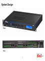
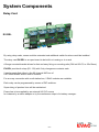
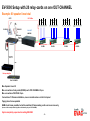
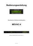
ic audio
EV-5000 Setup Guide
Audio Matrix for Voice-Alarm applications
Compliant with EN 60849
This document will give you a brief overview
about possible project setups with EV-5000.
Please note that the final layout of your
system design is related to the requirements
of the tender / project details.
Therefore this document will only highlight
a selection of common setups.
10/2009
System Design
Front
Rear
-1-
System Components
EV-5000 Main Unit
This is the head of your EVAC-system packed with clever features:
Connection of four 100V power amplifiers and one backup amplifier, both supervised
4 transformer balanced line outputs to drive four power amplifiers
Each line output has ist own volume, treble and bass controls
1 Line input (for instance for background music) with
separate level control for each output
1 Line input (AUX) with contact activating for instance for spotplayer with
separate level control for each output
Transformer balanced audio output to drive a backup amplifier
Connection of 2 Fireman callstations, one on rearside and one on front panel,
Mic capsules and control wires are supervised.
Programmable preannouncement chime
Chime for breaks
2 supervised emergency announcements (EMY) with contact activating
1 stored message (MSG) for instance for shop closing announcement
Relay contact to control priority override relays, which is active on calls from
fireman MICs when playing an emergency announcement and during the automatic setup run.
Up to 10 units cascadable in a master/slave configuration.
Easy programming by push buttons
Each zone output is supervised for open line, short circuit
impedance deviation and short to earth
-2-
System Components
Call Stations
EV-PAGE
The call station EV-PAGE can address up to 80 zones.
By means of a numeric keyboard and a display all functions can be operated very comfortable.
In Addition there are control keys for single call, group call and “All call” as well as for
programming and starting emergency announcement 1.
The busy status is shown in the display as clear text and by a red luminous ring
on the gooseneck microphone.
The programming function allows to switch the BGM on or off, to label the zones, so that they
are shown in the display and to allocate an address.
EV-EVAC 1
The Fireman desktop call station EV-EVAC 1 is equipped with an “All call” key.
This call station has highest priority. The dynamic capsule and the control leads are monitored.
-3-
System Components
Call Stations
EV-P4
The Subzone callstation EV-P4 is able to address up to 4 zones.
There are 4 call buttons as well as a LED to indicate a busy condition.
Any zone can be defined, “All Call” too.
Fireman handheld microphone
The Fireman handheld microphone EV-EVAC-MIC is equipped with PTT-button for “All call”.
The handheld MIC has highest priority too.
The dynamic capsule and the control leads are monitored.
-4-
System Components
Relay-Card
EV-REL
By using relay cards, zones could be extended and additional switch functions could be installed.
The relay card EV-REL is an open board to be built in a housing or in a rack.
A flange mounted bracket allows for fast and easy fixing on mounting rails (DIN rail 35x7,5 or 35x15mm).
EV-REL provides 4 relays (R1...R4) with 2 dry changeover contacts each.
It can be controlled either by the 80-channel MIC bus of
a EV-5000 Master and/or control contacts.
For an easy connection with a call station bus, 2 RJ45 sockets are available.
Each relay can be programmed by means of DIP-switches.
Supervising of speaker lines will be maintained.
Power has to be supplied by an external 24V DC source
for instance by a mains adaptor or by the continuous output of a battery manager.
-5-
Setup - Basics
Minimum
Using the smallest solution you can manage up to 4 speaker lines with one EV-5000.
If you don’t need any surveillance according to EN 60849 you can also use the callstation EV-P4.
To fullfill EN 60849 you have to use EV-EVAC 1 and / or EV-PAGE / EV-EVAC MIC.
The minium setup without EN 60849 compliance follows this layout:
EV-P4
CH 1 OUT
CAT5
AMP 480
Audio Out +
100V Linie
EV-5000
Speaker Line 1 (100V)
Audio Out +
100V Linie
CH 2 OUT
AMP 480
Speaker Line 2 (100V)
RAC 02 CD/MP3
Audio Out +
100V Linie
CH 3 OUT
LINE-Source @ option
AMP 480
Audio Out +
100V Linie
Speaker Line 3 (100V)
CH 4 OUT
AMP 480
Speaker Line 4 (100V)
-6-
Setup - Basics
Expansion
Of course you have several options to expand your EVAC-System up to 80 speaker lines.
You can do this in three different ways:
1. Cascading of EV-5000 units
Connect 1 Master unit
with up to 9 Slave units
to realize up to 40 speaker lines.
Each unit controls 4 speaker lines.
Please note:
Every Slave unit provides
one additional LINE-INPUT, one additional
soundfile player beside the speaker line expansion.
2. Expansion by relay cards
100V Line Out
Connect serveral relay cards with your Master
unit to expand the number of speaker lines.
Each relay cards controls
4 speaker lines.
This is a very cost-saving
method to expand the system.
Speaker Lines 1-4
(100V)
You will find more details in the next section.
CH 1 OUT
AMP 480
Please note:
One relay card uses 1 one of the 4 OUT channels of EV-5000.
Therefore you will get 7 speaker lines in total
if you connect one relay card with EV-5000.
80 CH Bus
EV-REL
-7-
Setup - Basics
Expansion
3. Mixed setup: Cascading & additional relay cards
Connect several Slave units with your Master unit and additional relay cards to expand the number of speaker lines
Please note: By choosing this setup you can benefit from the cost-saving expansion of speaker lines the relay cards
and you will get additional LINE-INPUTS and soundfile memories of the Slave units.
CAT5
Speaker Lines 1-4 (100V)
100V Line Out
EV-EVAC 1
EV-PAGE
CH 1 OUT
AMP 480
DIN 5-pole
Audio Out +
100V Linie
EV-5000
(1)
EV-REL (1)
CH 2 OUT
AMP 480
80 CH Bus
Audio Out +
100V Linie
CH 3 OUT
EV-REL (2) = Speaker Lines 5-8 (100V)
EV-REL (3) = Speaker Lines 9-12 (100V)
AMP 480
LINE
CH 4 OUT
Audio Out +
100V Linie
Speaker Lines 13-16 (100V)
AMP 480
Backup-Amplifier
100V Line Out
EV-REL (4)
Cascade
Speaker Lines 17-20 (100V)
CH 1 OUT
AMP 480
EV-5000
(2)
Audio Out +
100V Linie
EV-REL (5)
CH 2 OUT
EV-REL (6) = Speaker Lines 21-24 (100V)
AMP 480
CH 3 OUT
EV-REL (7) = Speaker Lines 25-28 (100V)
AMP 480
CH 4 OUT
EV-REL (8) = Speaker Lines 29-32 (100V)
AMP 480
Backup-Amplifier
As we have learned now which setups are possible
lets have a look at some common setups
which are suitable for many project layouts.
-8-
EV-5000 Setup with 20 relay-cards on one OUT-CHANNEL
Example: 80 speaker lines total
80 CH Bus
CAT5
Speaker Lines 1-4
(100V)
EV-EVAC 1
EV-PAGE
Speaker Lines 5-8
(100V)
Speaker Lines 9-12
(100V)
Speaker Lines 77-80
(100V)
EV-REL
EV-REL
CH 1 OUT
AMP 480
DIN 5-pole
Audio Out +
100V Linie
DC Input: 24V
CAT5 Input:
EV-PAGE
EV-5000
CAT 5 Looping of EV-PAGE
EV-REL
EV-REL
Audio Out +
100V Linie
LINE
Backup-Amplifier
RAC 02 CD/MP3
Max. Speaker Lines: 80
Max. connection of relay cards (EV-REL) each OUT-CHANNEL: 20 pcs.
Max. connection of EV-PAGE: 8 pcs.
Connection of 2 Fireman callstations, one on rearside and one on the front panel
Paging into all zones possible
BGM into all zones possible, but will be switched off when making a call even to one zone only
(because in this example all audio signals are distributed by only one OUT-CHANNEL)
System completely supervised according EN 60849
-9-
EV-5000 Setup with several relay-cards
Example: 48 speaker lines total
80 CH Bus
CAT5
Speaker Lines 1-4
(100V)
EV-EVAC 1
EV-PAGE
Speaker Lines 5-8
(100V)
Speaker Lines 9-12
(100V)
CH 1 OUT
AMP 480
DIN 5-pole
EV-5000
Audio Out +
100V Linie
DC Input: 24V
CAT5 Input:
EV-PAGE
CAT 5 Looping of EV-PAGE
EV-REL
EV-REL
EV-REL
Speaker Lines 17-20
(100V)
Speaker Lines 21-24
(100V)
EV-REL
EV-REL
100V Line Out
Speaker Lines 13-16
(100V)
Audio Out +
100V Linie
Audio Out +
100V Linie
CH 2 OUT
AMP 480
Backup-Amplifier
DC Input: 24V
CAT5 Input:
EV-PAGE
CAT 5 Looping of EV-PAGE
EV-REL
Audio Out +
100V Linie
Speaker Lines 25-28
(100V)
Speaker Lines 29-32
(100V)
Speaker Lines 33-36
(100V)
CH 3 OUT
AMP 480
LINE
DC Input: 24V
CAT5 Input:
EV-PAGE
CAT 5 Looping of EV-PAGE
EV-REL
EV-REL
EV-REL
Audio Out +
100V Linie
Speaker Lines 25-28(100V)
RAC 02 CD/MP3
Speaker Lines 29-32
(100V)
Speaker Lines 33-36
(100V)
CH 4 OUT
AMP 480
DC Input: 24V
CAT5 Input:
EV-PAGE
CAT 5 Looping of EV-PAGE
EV-REL
EV-REL
Max. Speaker Lines: 80
Max. connection of relay cards (EV-REL) on the OUT-CHANNELs: 20 pcs.
Max. connection of EV-PAGE: 8 pcs.
Connection of 2 Fireman callstations, one on rearside and one on the front panel
System completely supervised according EN 60849
- 10 -
EV-REL
Good to know...
Beside the different setups, there are some points which
are important for a suitable and cost-effective planning of the project.
Please keep them in mind and they will safe you time and money...
1 Maximum power for one speaker line:
You can use up to 800 W for one speaker line...so plenty of speakers are possible.
2 Using callstation EV-P4:
As you remember this is a callstation for 4 speaker lines.
If you like to page into more areas, you have
to use EV-PAGE (up to 80 speaker lines).
3 Maximum number of callstations EV-P4:
Simple thing....up to 30 pcs. can be connected with each EV-5000 Master unit
or the EV-5000 Slave unit. Please note that with EV-P4 you can only page into the
4 speaker zones of the Slave unit (if provided you connected EV-P4 with the Slave).
4 Maximum number of callstations EV-PAGE:
You can connect up to 8 EV-PAGE with each EV-5000 Master unit.
5 Running different priority levels:
Of course you have many different priority levels, lets see:
(1 = highest, 10 = lowest)
1. Fire MIC 1 = fireman MIC connected to rear side pluggable screw terminals
2. Fire MIC 2 = fireman MIC connected to front side DIN-connector
3. Emergency announcement 1 (EMY1)
4. Emergency announcement 2 (EMY2)
5. AUX with request
6. Message (MSG)
7. EV-PAGE 80 zone call station
8. EV-P4 sub zone callstation, 4 zones
9. Chime
10. Background music
- 11 -
Good to know...
6 Priority EV-PAGE vs. EV-PAGE:
The callstation EV-PAGE which has been activated first (call, e.g.) has
priority over other EV-PAGE callstations.
7 Priority EV-P4 vs. EV-P4:
If you are using two EV-P4 callstations at the same time, you will hear
both calls. There is no priority-setting for each of the EV-P4 callstations.
8 Maximum cable length of the callstations:
The maximum cable length of the callstations should not exceed 500m.
9 Documentation of the system configuration:
You can easily connect the EV-5000 Master with a PC (by RS232-interface) and
by Hyper-Terminal (integrated in Windows©) to export the system
settings and error messages into a text file.
Main Menu
EV5000
KEY 1 :
KEY 2 :
KEY 3 :
KEY 4 :
KEY 5 :
KEY 6 :
KEY 7 :
Caution
installed components
Audio level
Audio and Relaisprogramming
Misc. Setting
Text input
Errors
Factory Setting
!! Delets all Settings
- 12 -
Good to know...
10 Supervision of the system
The EVAC-System is supervised according to EN 60849 on different levels.
In the following we will show you some details of the supervision.
First of all: The EV-5000 detects all connected components by
an automatic set-up run. Impedance levels will be measured
and taken as reference values. The tolerances of the supervision can be adjusted
by the user. Factory-made these default values are defined:
Alarm Message: Interruption
= The measuring result shows an increased impedance of more
then 30% compared to the reference value.
Alarm Message: Short Circuit
= The measuring result shows a decreased impedance of more
then 30% compared to the reference value.
Alarm Message: Short to earth
= The measuring result shows an deviance of the direct-current voltage.
(Measuring of the direct-current voltage in permanent measuring cycles)
Supervision of Amplifiers
= The amplifiers are supervised by an 22 kHz test tone.
Supervision of Emergency Callstation
= The control wire is supervised by the measuring of resistors (in the callstation)
= The capsule of the microphone is supervised by a 1 kHz test tone.
Supervision EV-PAGE
= The supervision of the callstation is done by measuring the
direct-current voltage in permanent measuring cycles.
- 13 -
Good to know...
11 Deactivation of supervision
In some projects it is required to deactivate the supervision of
certain speaker lines - and of course you can do this also with EV-5000.
You will find further and detailed information in the user manual.
12 Connection of more then one audio source with one EV-5000 Master
The EV-5000 Master offers one LINE-IN Input for audio sources and one
AUX-Input (activated by request).
If you like to connect a second or third line LINE-IN unit (like a CD-Player)
with the EV-5000 Master to switch between those sources you can use
the ic audio program selector PW 6 RUP (6 programs)
or the 8-channel preamplifier PRE-AMP 08.
PW 6 RUP
PRE-AMP 08
- 14 -
Good to know...
13 Operation by using a Master-Slave configuration
If you use Slave-units you will benefit from these additional functions for
each of the connected Slave-units (the Slave-unit is a full-fledged EV-5000
which has been set to Slave-operation by jumpers):
1 Chime before calls (individual for EV-P4,
EV-PAGE has been setup by the progamming of the Master)
2 stored alarm messages
1 AUX-Input (activated by request)
1 Message (stored announcement)
1 chime for breaks
1 LINE-IN Input for background music
By using these additional functions you can play background music
in the “Slave-Area” and also different background music in the
“Master-Area” at the same time, e.g.
This can be very helpful for projects with different background music routings
and as well paging for all dedicated areas.
Furthermore the setup run of the connected Slave-units will start automatically
if the setup run of the Master has been started before.
Therefore the complete supervision of the Master/Slave-system is managed
very user-friendly.
THANK YOU FOR YOUR ATTENTION!
- 15 -
For best Sound Performance
get ic audio
Amplifiers and Speakers!
ic audio GmbH
Boehringerstraße 14a
68307 Mannheim /
Germany
Fon:+49(0)621/ 77096-0
Fax:+49(0)621/ 77096-26
www.ic-audio.com
Email: [email protected]