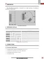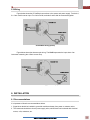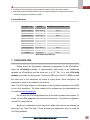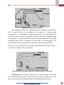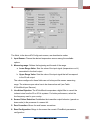
1
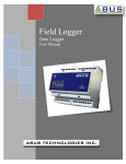
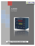
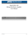
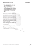
ATxIsoBlock Universal Temperature Transmitter User Manual ABUS TECHNOLOGIES INC. ATxIsoBlock WARNING This manual should be passed on to the end user. The contents of this manual are subject to change without prior notice. All rights reserved. ABUS gives no warranty of any kind with regard to this manual, including, but not limited to, fitness for a particular purpose. If any question arises or errors are found, or if any information is missing from this manual, please inform your supplier or inform at [email protected]. The specifications mentioned in this manual are limited to those for the standard type under the specified model number break-down and do not necessarily apply for customized instruments. Please note that changes in the specifications, construction, or component parts of the instrument may not immediately be reflected in this manual at the time of change. If the customer or any third party is harmed by the use of this product, ABUS assumes no responsibility for any such harm owing to any defects in the product which were not predictable, or for any indirect damages. Although Warning hazards are related to personal injury, and Caution hazards are associated with equipment or property damage, it must be understood that operation of damaged equipment could, under certain operational conditions, result in degraded process system performance leading to personal injury or death. Therefore, comply fully with all Warning and Caution notices. Information in this manual is intended only to assist our customers in the efficient operation of our equipment. Use of this manual for any other purpose is specifically prohibited and its contents are not to be reproduced in full or part without prior approval of Technical Communications Department, ABUS Technologies HEALTH AND SAFETY To ensure that our products are safe and without risk to health, the following points must be noted: 1. The relevant sections of these instructions must be read carefully before proceeding. 2. Warning labels on containers and packages must be observed. 3. Installation, operation, maintenance and servicing must only be carried out by suitably trained personnel and in accordance with the information given. Any deviation from these instructions will transfer the complete liability to the user. 4. Normal safety precautions must be taken to avoid the possibility of an accident occurring when operating in conditions of high pressure and/or temperature. 5. Chemicals must be stored away from heat, protected from temperature extremes and powders kept dry. Normal safe handling procedures must be used. 6. When disposing of chemicals ensure that no two chemicals are mixed. Safety advice concerning the use of the equipment described in this manual or any relevant hazard data sheets (where applicable) may be obtained from the Company address on the back cover, together with servicing and spares information. ABUS TECHNOLOGIES INC. 2 ATxIsoBlock . CATALOGUE Contents Page No. 1. Introduction 4 2. Presentation 4 4 Technical Parameters 3. Dimensions 5 4. Ordering Details 5 5. Connections 5 5 6 1. Connector Specification 2. Wiring 6. Installation 1. Recommendation 2. Input Sensors 6 6 7 7. Configuration 7 8. Maintenance 10 10 Calibration of Instruments 9. Safety Precautions 11 10. Warranty 11 ABUS TECHNOLOGIES INC. 3 ATxIsoBlock 1. INTRODUCTION The ATxIsoBlock is a 2-wire in-head temperature transmitter with galvanic isolation between input and output, microprocessor based designed for the flexibility of accepting mV, Pt100 and a variety of thermocouples as the input sensor. The ATxIsoBlock delivers a scalable linear 4-20mA output current proportional to the sensor temperature. User-friendly configuration software is provided for parameter setup, including sensor type, temperature range, etc. 2. PRESENTATION Technical Parameters Sensor input: User defined. The supported sensors are listed in table 6.2 ATxIsoBlock Input Sensors, along with their maximum ranges. Thermocouples: Types J, K, R, S, T, N, E and B according to IEC 60584. Impedance >> 1 M Pt100: Excitation: 180 A. 2 or 3-wire connection (for 2-wire sensors, tie terminals 2 and 3 together). = 0.00385, according to IEC 60751. Voltage: 0 a 50mVdc. Impedance: 1 M Output: 2-wire 4-20 mA, linear with respect to the measured temperature. Total accuracy: Better than 0.25% of the maximum range for thermocouples and 0,15% for Pt100 and voltage; Resolution: 0,001 mA (14 bits). Response Time: < 500 ms; Power supply: 12 to 35 Vdc, across the transmitter; Maximum load (RL): RL (max.)= (Vcc – 12) / 0,02 [] Where, Vcc= Power supply voltage Operating Temperature: -40 to 85 °C Humidity: 0 a 90% RH Electromagnetic compatibility: EN 50081-2, EN 50082-2 Isolation: 1500Vac for 1 minute between sensor input and the 4 ~ 2 mA loop. Housing: ABS plastic. Dimensions: 44mm (diameter) x 25mm (height). Polarity inversion protection: Internal Cold junction compensation for thermocouples. ABUS TECHNOLOGIES INC. 4 ATxIsoBlock 3. DIMENSIONS The ATxIsoBlock transmitter is intended for in head mounting. Its drawing is presented in figure below: ATxIsoBlock Dimensions 4. ORDERING DETAILS TYPE Product Isolation DESCRIPTION ATx Iso N Mounting Output Accessories B R Universal Temperature Transmitter 2-wire system Isolation 1500 Vac Input, Output and Power supply None Head Mounting DIN Rail Mounting D 4 ~ 20 mA dc V 0 ~ 10 V dc +C Configurator along with software N None, factory setting Example: ATx > Iso > B > D > N 5. CONNECTIONS 5.1 Connector Specification Insulating material: Polyamide, self-extinguishing to UL 94, V-0; Connection wire cross section: 0,14-1,5 mm² / AWG 28-14; Screw tightening torque: 0,8 Nm / 7.0 lb-in Terminal block: CuZn ABUS TECHNOLOGIES INC. 5 ATxIsoBlock 5.2 Wiring Figure below shows the ATxIsoBlock connections to the sensor and power supply. Terminals 1, 2 e 3 are used for sensor input. For 2-wire Pt100, terminals 2 and 3 shall be connected together. ATxIsoBlock wiring (Pt100) Figure below shows the thermocouple wiring. The LOAD represents the input shunt of an instrument measuring the 4-20mA current loop. ATxIsoBlock wiring (Thermocouple) 6. INSTALLATION 6.1 Recommendations It is important to follow the recommendations below: 1. Signal wires should be installed in grounded conduits and away from power or contactor wires. 2. The instrument should have its own power supply wires, which should not be shared with electrical motors, coils, contactors, etc. ABUS TECHNOLOGIES INC. 6 ATxIsoBlock 3. Installing RC filters is strongly recommended at contactor coils or any other inductors. 4. System failure should always be taken into account when designing a control panel to avoid irreversible damage to equipment or people. 6.2 Input Sensors SENSOR TYPE RANGE MINIMUM MEASUREMENT SPAN Thermocouple K -150 to 1370 °C 100 °C Thermocouple J -100 to 760 °C 100 °C Thermocouple R -50 to 1760 °C 400 °C Thermocouple S -50 to 1760 °C 400 °C Thermocouple T -160 to 400 °C 100 °C Thermocouple N -270 to 1300 °C 100 °C Thermocouple E -90 to 720 °C 100 °C Thermocouple B 500 to 1820 °C 400 °C Pt100 -200 to 600 °C 40 °C Voltage 0 to 50 mV ATxIsoBlock Input Sensors 5 mV 7. CONFIGURATION Please check the configuration parameters programmed in the ATxIsoBlock, using the ATxConfig software. A communication path needs to be established between the ATxIsoBlock and the serial port of a PC. The 1.5 m long ATxConfig Adaptor is provided for this purpose. Connect its DB9 end to the PC COMM port and the other end to the transmitter as shown in figure below. Once configured, the transmitter is ready to be installed in the process. Note: The ATxConfig Adaptor and Software can be purchased separately from ABUS or one of its distributors. The latest release of this software can be downloaded from our web site www.abustek.com Do not save the ATxConfig software into a file which contains accent marks. To install, run the ATx_setup.exe and follow the instructions. To install de configurator, run the ATx_setup.exe file. Serial port configuration errors may occur when other devices are sharing the same port (ex.: Palm Hot Sync). Close all serial port applications prior to using the ATxConfig software. ABUS TECHNOLOGIES INC. 7 ATxIsoBlock Adaptor connections to the ATxIsoBlock The transmitter requires to be powered during the configuration. Depending on the PC used, the power can be supplied by the serial port. To assure proper communication, it is recommended to apply external power to the ATxIsoBlock. The ATxConfig Adaptor provides a 9 V battery socket for powering the transmitter during the configuration. A jumper wire must be connected between terminals 1and 6 during configuration when power is provided by the serial port or ATxConfig battery. The jumper offends isolation and must be removed before installing the ATxIsoBlock. Note: Do not use the battery if the transmitter is being powered by another supply or connected to the process, as in figure below. ATxIsoBlock-ATxConfig Adaptor wiring (loop powered).Terminal 5 is left opened. ATxConfig screen in shown in figure below. All user parameters can the seen and/or modified by either typing a value or selecting among the available options. The help menu provides further information about the software and the transmitter. ABUS TECHNOLOGIES INC. 8 ATxIsoBlock ATxConfig main screen The fields, in the above ATxConfig main screen, are described as under: 1. Input Sensor: Choose the desired temperature sensor among the available options. 2. Measuring range: Defines the beginning and the end of the range. a. Lower Range Value: Sets the value of the input signal (temperature or mV) associated to the 4mA output. b. Upper Range Value: Sets the value of the input signal that will correspond to the 20 mA output The values configured in these fields can not be beyond the sensor measuring range. The minimum span value has to be observed as well (see Table ATxIsoBlock Input Sensors). 3. Line Noise Rejection: The ATxIsoBlock incorporates a digital filter to cancel the induced noise from the 50 or 60 Hz systems. For better performance, select the line frequency used in your country. 4. Sensor Failure Detection: Establishes the transmitter output behavior (upscale or down-scale) in the presence of a sensor fail. 5. Zero Correction: Allows for small sensor corrections. 6. Read Configuration: Brings to the screen the current ATxIsoBlock parameters configuration. ABUS TECHNOLOGIES INC. 9 ATxIsoBlock 7. Apply: Sends a new configuration to the transmitter. 8. Device Information: The Device Information box contains relevant data concerning a particular ATxIsoBlock assistance department. Note: The factory default configuration is (unless otherwise specified or ordered): Pt100 input, 0 to 100 °C 60 Hz filtering and upscale (20 mA) output for sensor failure. 8. MAINTENANCE Calibration of Instruments All input types and the 4-20mA output current are factory calibrated. However, a manual offset trim is implemented to provide fine adjustments to the signal in the field. This is accomplished by means of short circuiting terminals 4 (Zero) and 1(-). The transmitter waits 2 seconds before it starts changing the offset. The offset adjustment is capable of varying the output current by an amount equal to 0.80mA relative to the original calibration. After reaching the maximum value (0.80mA above the original current), the output is driven instantly to –0.80mA below the original current, and continues increasing. When the desired output current (offset) is reached, opening the jumper will cause the ATxIsoBlock to acknowledge the new offset value. Fine trimming is possible with momentary (2s minimum) jumper contact. The offset correction can also be accomplished by the ATxConfig software. See in figure ATxConfig main screen, the Zero Correction field for this purpose. The serial adaptor can be connected to the transmitter while it is operating in the process. Note: when using a Pt100 simulator, make sure the ATxIsoBlock Pt100 excitation current (0.17 mA) s compatible with the simulator specification. The input sensors are listed in table ATxIsoBlock Input Sensor, along with the maximum and minimum ranges accepted by each one. The ATxConfig software will allow only configurations that are consistent with the data in this table. ABUS TECHNOLOGIES INC. 10 ATxIsoBlock 9. SAFETY PRECAUTIONS 1. The unit should be powered for 15 minutes before use. 2. Use in ambient temperature of 0-60˚C. 3. Avoid vibrations, shock, excessive dust, corrosive chemical materials or gaseous environment. 4. Input wire should not be too long. If measured signal have to be far away from the unit, please use 2-core shielded cable. 5. Use this instrument in the scope of its specifications, otherwise fire or malfunctions may result. 6. Contact of the instrument, with organic solvents or oils should be avoided. 7. Do not turn on the power supply until all of the wiring is completed. Otherwise electrical shock, fire or malfunction may result. 8. Do not disassemble, repair or modify the instrument. 9. All connections should be tightened properly. 10. Power supply should be constant, should not be fluctuating. 10. WARRANTY ABUS provides the original purchaser of this instrument a one (1) year warranty against defects in material and workmanship under the following terms: The one year warranty begins on the day of shipment as stated on the sales bill. During the warranty period all costs of material and labor will be free of charge provided that the instrument does not show any evidence of misuse. For maintenance, return the instrument with a copy of the sales bill to our factory. All transportation and insurance costs should be covered by the owner of the equipment. Should any sign of electrical or mechanical shock, abuse, bad handling or misuse be evident the warranty voids and maintenance costs will be charged. ABUS TECHNOLOGIES INC. www.abustek.com, E-Mail: [email protected] ABUS TECHNOLOGIES INC. 11