1
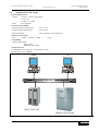
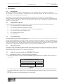
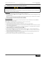
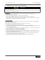
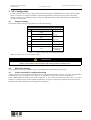
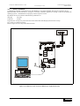
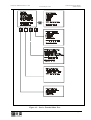
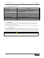
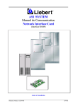
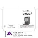
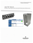
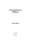
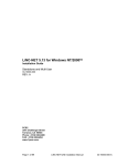
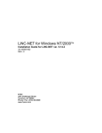
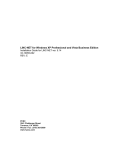
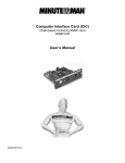
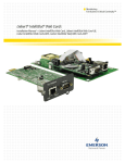
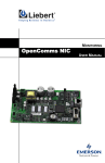
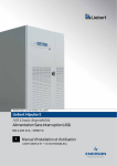
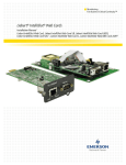
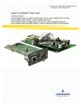
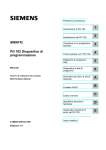
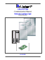
UPS SYSTEM
Communication Manual
Network Interface Card
(SNMP Interface)
Installation Guide
Ref.: 6313045L
(05/00)
Communication System Manual
(SNMP Interface)
UPS System: HIPULSE and Series 7200
Network Interface Card
OPENCOMMS
NETWORK INTERFACE
CARD
IMPORTANT
This manual contains information on interfacing with a Network Management System (NMS)
using the SNMP protocol
for use with Series 7200 and HIPULSE UPS Systems.
Read this manual right through
before beginning installation work.
(05/00)
Pag. iii
UPS System: HIPULSE and Series 7200
Network Interface Card
Communication System Manual
(SNMP Interface)
WARNING
Personnel operating on any apparatus referred in this manual must know extensively the product.
The UPS must be commissioned and serviced by an engineer approved by the manufacturer (or his agent).
Failure to do so could result in personnel safety risk, equipment malfunction and invalidation of warranty.
ELECTROMAGNETIC COMPATIBILITY
This equipment complies with the requirements of the EMC Directive 89/336/EEC.
Continued compliance requires installation in accordance with these instructions and the use of manufacturer
approved accessories only.
GUIDE TO THE INSTRUCTIONS
The warning triangle indicates all the personal safety instructions.
Follow these instructions carefully to avoid injury.
Pag. iv
(05/00)
Communication System Manual
(SNMP Interface)
UPS System: HIPULSE and Series 7200
Network Interface Card
Table of Contents
1
General Description................................................................................................................................................... 1-1
1.1
1.2
1.3
1.4
2
Operator Panel...................................................................................................................................................... 1-1
Operator Logic Board .......................................................................................................................................... 1-1
Network Interface Card (NIC) ............................................................................................................................. 1-1
Specifications (NIC Card):................................................................................................................................... 1-2
Installation ................................................................................................................................................................. 2-1
2.1
2.2
2.3
2.4
2.5
2.5.1
2.5.2
2.5.3
3
Introduction .......................................................................................................................................................... 2-1
Composition of the kit.......................................................................................................................................... 2-1
User Connections ................................................................................................................................................. 2-1
Physical Location ................................................................................................................................................. 2-1
Cable for connection with the ETHERNET Network ......................................................................................... 2-1
Cable length from floor to connection point in the equipment ....................................................................... 2-1
Installing the NIC card in the Liebert UPS cabinet (7200 Series).................................................................. 2-2
Installing the NIC card in the Liebert UPS cabinet (HIPULSE) .................................................................... 2-4
Programming parameters on the Operator Panel Display......................................................................................... 3-1
3.1
Operator Panel...................................................................................................................................................... 3-1
3.1.1
Selection of the IGMNet Protocols from Operator Panel menu..................................................................... 3-2
4
NIC Configuration..................................................................................................................................................... 4-1
4.1
4.2
4.3
4.4
4.4.1
4.5
5
5.1
5.2
5.3
5.4
5.5
Jumpers Settings................................................................................................................................................... 4-1
DIP Switch Settings.............................................................................................................................................. 4-1
Serial connection for configuration/setup ............................................................................................................ 4-1
Service Terminal .................................................................................................................................................. 4-2
Description of the windows of the Service Terminal Menu ........................................................................... 4-4
UPS MIB 1628..................................................................................................................................................... 4-5
Technical description of the protocol........................................................................................................................ 5-1
SNMP Protocol .................................................................................................................................................... 5-1
MIB data points.................................................................................................................................................... 5-1
Alarms reported via SNMP.................................................................................................................................. 5-4
System Reset......................................................................................................................................................... 5-4
Non volatile Memory ........................................................................................................................................... 5-4
(05/00)
Page v
UPS System: HIPULSE and Series 7200
Network Interface Card
Pag. vi
(05/00)
Communication System Manual
(SNMP Interface)
UPS System: HIPULSE and Series 7200
Network Interface Card
Communication System Manual
(SNMP Interface)
1 General Description
The components that are involved for monitoring the UPS using the SNMP protocol are described below.
1.1
Operator Panel
A display and control panel on the front of the UPS permits monitoring of the state of the UPS System, including
electrical measurements and status messages.
The Panel is driven by the Operator Logic board (P/N 4550005F) which sends data out continuously over the
Operator Logic RS232 serial line.
This data is physically contained in a single string which the Operator Logic Board sends every 1-2 seconds, or,
under special conditions, every 3-4 seconds.
1.2
Operator Logic Board
This is the centre of the entire system. It is located on the rear of the UPS Operator access door and communicates with
UPS Logic. It has a backup battery to maintain data in memory in the event of a power failure and a clock to assign a
date and time to events.
The Logic Board performs the following functions:
• receives data from the operator panel
• stores data in memory
• transmits data upon request over the RS232 on the network using the IGMNet protocol
1.3
Network Interface Card (NIC)
The Liebert Network Interface Card (NIC) provides Ethernet connectivity for your Liebert UPS equipment.
Operating status is monitored and alarms are communicated via the network.
The NIC transforms Liebert units into intelligent managed nodes in your network, enabling in-band communications
with network management systems (NMS) that monitor the well-being of your computing/communication
infrastructure.
The NIC can be used in a network in according to Ethernet IEE 802.3.
The NIC communicates using the SNMP v1 protocol.
This protocol allows simple integration into the network management system, thus leveraging prior investment and
established procedures.
WARNING
The NIC card is sensitive to elecrostatic charge and
therefore must only be bondled while wearing an antistatic wriststrap.
(05/00)
Page 1-1
UPS System: HIPULSE and Series 7200
Communication System Manual
(SNMP Interface)
Network Interface Card
1.4
Specifications (NIC Card):
Electrical Requirements
Voltage:
16VAC to 28VAC Single Phase
47 to 63 Hz
11VDC to 39.5VDC
Power:
6VA maximum
Environmental Conditions
Operating Ambient Temperature :
0°C to 40°C
Storage Ambient Temperature :
-20°C to 60°C
Relative Humidity :
10% to 90% RH (non-condensing)
Dimensions and weight: :
Net:
178mm x 102mm x 38mm
0.2kg
Compatibility:
3-Phase UPS modules:
Series 7200
HIPULSE UPS System
Output Connectors
To ETHERNET connection (J3): socket (RJ45 to 8 pin)
DTE Serial Port (P18): DB9M
PC
NMS
Ethernet
Series 7200 UPS
Hipulse UPS System
Figure 1-1 – Typical System Configuration.
Page 1-2
(05/00)
UPS System: HIPULSE and Series 7200
Communication System Manual
(SNMP Interface)
Network Interface Card
2 Installation
2.1
Introduction
The NIC may be ordered as a factory-installed option, or in a kit for field-retrofit to existing Liebert UPS units.
As a member of the Liebert family of communications and monitoring products, the NIC is backed by the most
extensive field service organization in the industry.
If ordered as a factory-installed option, proceed directly to subsection on User Connections (see Paragraph 2.3).
If field installed, the option kit on the UPS System must be mounted by an engineer approved by the manufacturer (or
his agent). Contact Liebert Hiross Services at the address given in the start of this manual, regarding installation,
operation, or warranty issues.
2.2
Composition of the kit
The kit P/N 4645111D (for HIPULSE UPS Systems) or the kit P/N 4645114G (for Series 7200 UPS) comprises:
♦
N°1 Network Interface Card (NIC) P/N 4590063X.
♦
N°1 Flat cable sheathed for communication signals.
♦
N°1 Twisted pair of wires equipped with a ferrite core for powering the card.
♦
N°1 Protective metal cover for the NIC Card.
♦
N°1 Installation manual on CD.
♦
Fixing components.
2.3
User Connections
Two user connections are required: a permanent network connection (see Fig. 2-3), and a temporary serial connection
for configuration/setup of the NIC card (see Fig. 4-1).
See the Network Administrator to arrange a network connection to the Liebert equipment. The NIC communicates via
standard 10baseT Ethernet network connection. Route the 10baseT cable to the Liebert unit and connect to J3, the RJ45
socket on the interface card. The NIC card will operate with any 10baseT Ethernet, regardless of the operating system
used. Proceed to configuration as detailed in Section 4 prior to physically installing the card.
2.4
Physical Location
The Operator Logic board and NIC card are located on the inside of the UPS access door (refer to Figures 2-1 and 2-2),
protected by a metal cover and connected to the other electronic boards in the UPS. The NIC connects the UPS with a
NMS through a RJ45 plug terminal (J3). As shown in figure 2-3.
2.5
Cable for connection with the ETHERNET Network
2.5.1
Cable length from floor to connection point in the equipment
The useful cable length for connection with the ETHERNET Network from the floor to the RJ45 socket (connector J3)
on the UPS is:
Network Interface Card (NIC)
UPS
HIPULSE
Length (mm)
7200 Series
1200
2000
Table 2-1
The connection distance from the NIC card to the ETHERNET network depends on the positioning of the UPS on site;
the maximum cable length is 100 meters up to the last HUB, REPEATER, SWITCH or other active device in the LAN
network.
The cable type should be a screened FTP Category 5 network cable.
(05/00)
Page 2-1
UPS System: HIPULSE and Series 7200
Network Interface Card
2.5.2
Communication System Manual
(SNMP Interface)
Installing the NIC card in the Liebert UPS cabinet (7200 Series)
WARNING
Before installing the kit P/N 4645114G for Network Interface Card (P/N 4590063X), in the 7200 Series UPS, it is
necessary to power down that unit.
To maintain continuity of supply, the load should first be transferred to the maintenance bypass circuit following
the procedure given in the UPS user manual.
Fixing the card
The NIC card is installed in the rear of the operator access door (see figure 2-1).
1. Mount the aluminium plate n of the NIC card o in the location inside the cabinet, as shown in the figure 2-3, using
the supplied screws.
Note: The rear operator door has been modified to allow fixing of the NIC in this way. On older units it is sufficient
to fix the card in place using double-sided slicky tape (not supplied).
2. Remove the metallic cover of the Logic Operator Board (4550005F).
Power and connections
Before installing the NIC card, it is necessary to setup local parameters to allow communication in an ETHERNET
network. Refer to Chapter 4 for details.
Refer to figure 2-3 to make the power and communication connectors to the NIC card.
1. Verify that the jumpers setting are as shown in the Table 4-1.
2. Connect the ribbon cable from P3 of the NIC to connector X8 on the Logic Operator Board.
3. Connect the power cable (prevoused on a ferrite core) from connector Tb3 (PWR) on the NIC card and to connector
X10 on the Logic Operator Board.
4. Connect the ETHERNET cable (type Category 5, as defined in paragraph 2.5.1) to the RJ45 socket (J3 on the NIC
card), after winding it twice around the loose ferrite core p.
5. Replace the metal cover over removed the Logic Operator Board.
6. Fix the outgoing ETHERNET cable, following the cable way shown in figure 2-1, using the supplied cable ties.
7. Mount the metal cover r (supplied) take care to connect the earth wire q to E1 on the NIC card and to the frame
using one of the fixing screws of the metal cover.
8. Close power isolators Q2 to supply power to the control logic and then setup the Programming parameters at the
Operator Panel Display (see Chapter 3) to complete the setup.
9. Return the UPS to Normal Operation, following the procedure given in the UPS user manual.
Page 2-2
(05/00)
UPS System: HIPULSE and Series 7200
Network Interface Card
Communication System Manual
(SNMP Interface)
Figure 2-1 – Location of the kit P\N 4645114G inside the Liebert 7200 Series cabinet.
(05/00)
Page 2-3
UPS System: HIPULSE and Series 7200
Network Interface Card
2.5.3
Communication System Manual
(SNMP Interface)
Installing the NIC card in the Liebert UPS cabinet (HIPULSE)
WARNING
Before installing the kit P/N 4645111D for Network Interface Card (P/N 4590063X), in the Hipulse UPS, it is
necessary to power down that unit.
To maintain continuity of supply, the load should first be transferred to the maintenance bypass circuit following
the procedure given in the UPS user manual.
Fixing the card
The NIC card is installed in the modem cavity on the rear of the operator access door (see figure 2-2).
1. Remove the ‘modem restrainer’ n.
2. Remove the metallic cover of the Logic Operator Board (4550005F)o.
3. Mount the NIC card p in the modem cavity, as shown in the figure 2-3, using the supplied screws.
Note: The modem cavity has been modified to allow fixing of the NIC in this way. On older units it is sufficient to
fix the card in place using double-sided slicky tape (not supplied).
Power and connections
Before installing the NIC card, it is necessary to setup local parameters to allow communication in an ETHERNET
network. Refer to Chapter 4 for details.
Refer to figure 2-3 to make the power and communication connectors to the NIC card.
10. Verify that the jumpers setting are as shown in the Table 4-1.
11. Connect the ribbon cable from P3 of the NIC to connector X8 on the Logic Operator Board.
12. Connect the power cable (prevoused on a ferrite core) from connector Tb3 (PWR) on the NIC card and to connector
X10 on the Logic Operator Board.
13. Connect the ETHERNET cable (type Category 5, as defined in paragraph 2.5.1) to the RJ45 socket (J3 on the NIC
card), after winding it twice around the loose ferrite core q.
14. Replace the metal cover over removed the Logic Operator Board.
15. Fix the outgoing ETHERNET cable, following the cable way shown in figure 2-2, using the supplied cable ties.
16. Mount the metal cover s (supplied) take care to connect the earth wire r to E1 on the NIC card and to the frame
using one of the fixing screws of the metal cover.
17. Close power isolators Q2 to supply power to the control logic and then setup the Programming parameters at the
Operator Panel Display (see Chapter 3) to complete the setup.
18. Return the UPS to Normal Operation, following the procedure given in the UPS user manual.
Page 2-4
(05/00)
UPS System: HIPULSE and Series 7200
Network Interface Card
Communication System Manual
(SNMP Interface)
X1 0
X8
Figure 2-2 – Location of the kit P\N 4645111D inside the Liebert Hipulse UPS cabinet.
(05/00)
Page 2-5
UPS System: HIPULSE and Series 7200
Network Interface Card
Communication System Manual
(SNMP Interface)
X10
X8
Figure 2-3 – Connecting the NIC card to the Operator Logic board.
Page 2-6
(05/00)
UPS System: HIPULSE and Series 7200
Network Interface Card
3
Communication System Manual
(SNMP Interface)
Programming parameters on the Operator Panel Display
During installation, a series of parameters must be programmed to permit the UPS to function with the IGMNet
protocol; this is done with the menu in the Operator Panel display.
Note: Modifications to set-up must be made strictly by qualified personnel only.
3.1
Operator Panel
The Operator Panel display is located on the front of the device. The function keys are used during programming to
accept current selections or modify them to suit the user’s needs.
The functions of individual keys are described below; refer to the User Manual for more detailed information.
ENTER
ENTER
Used to confirm selection and go on to the next window.
If a parameter has been entered or selected, it will be saved in memory when you
press ENTER.
ESC
ESC
ESC
ESC cancels the last action and returns to the previous window. If pressed twice, it
will take you back to the first window. Press ESC when entering data or parameters
to exit without saving.
MENU keys may be used to move the cursor around within the window to make a
selection.
UP
UP
MENU
DOWN
Moves the cursor up through available choices in the window. When a setting has
been selected, it moves the cursor one character to the right.
DOWN
Moves the cursor downward during selection. When a setting has been selected,
scrolls through the table of values stored in memory for that setting, with the
current value highlighted by the cursor.
Fig. 3-1 Operator Panel Keys
(05/00)
Page 3-1
UPS System: HIPULSE and Series 7200
Network Interface Card
3.1.1
Communication System Manual
(SNMP Interface)
Selection of the IGMNet Protocols from Operator Panel menu
NORMAL OPERATION
HH.MM.SS
DD.MM.YY
SW RELEASE
PANEL
UPS LOGIC
V xx.x
V xx.x
MEASUREMENT
>FUNCTION
MAINTENANCE
SETUP
<
ÏWRITE
SAVE©
ÐMOVE
EXIT ESC
ENTER PASSWORD
>00000000<
BATTERY TEST
GENERATOR
PANEL SETUP
>NEXT PAGE
• Default window.
This message is displayed in the default window during normal UPS operation;
the message reads ‘ECOMODE’ if the UPS is a single module configuration
operating in EcoMode.
• Information window.
Press ESC twice to display the UPS Logic board and Panel board software
release. This function is useful for upgrading software and finding out exactly
which functions are offered by the current version.
Press ESC again to return to the Default Window.
• Main Menu window.
Press ENTER from the Default Window to go to the main menu.
Press DOWN to go to the FUNCTION line in the menu. Press ENTER to
confirm your selection and go to the selected sub-menu.
A request for the numerical password will appear. To enter the password, use
the UP key to scroll through values (0 through 9) for each digit, and press
DOWN to go on to the next digit. When you have finished entering the
password, press ENTER, and confirmation or an error message will appear.
Select NEXT PAGE and press ENTER
<
The following procedures refer to setting of the IGMNet Protocol.
>PROTOCOLS
<
ON/OFF UPS CONTROL
RELOAD UPS DATA
RESET BUFFERS
>PROTOCOLS xxxxxx<
RESET PROTOCOL x
IGMNET SETUP
ÏROTATE
PROTOCOL
Page 3-2
SAVE©
EXIT ESC
xxxxxx
Select PROTOCOLS and press ENTER
The current setting of PROTOCOL xxxxxx will be displayed: it may be
LOCAL (default) \ REMOTE \ IGMNET.
To select the IGMNET protocol, use the menu button, press ‘UP’ to change to
IGMNET, then press ENTER.
Press ESC to return to the previous window.
(05/00)
UPS System: HIPULSE and Series 7200
Network Interface Card
Communication System Manual
(SNMP Interface)
After you have finished entering the settings, it is necessary to set the IGMNET protocol as the default protocol.
Complete the programming process by confirming all the data entered using the following window:
PROTOCOL IGMNET
>RESET PROTOCOL Y<
IGMNET SETUP
Select RESET PROTOCOL and press UP to select Y (YES), then press
ENTER.
Warning
If the user does not select ‘RESET PROTOCOL’ initialisation will not take place and the selected protocol will not
be applied.
Press ESC repeatedly to return to the Display window, moving back through the various windows until you get to the
default window.
(05/00)
Page 3-3
UPS System: HIPULSE and Series 7200
Network Interface Card
Page 3-4
(05/00)
Communication System Manual
(SNMP Interface)
Communication System Manual
(SNMP Interface)
UPS System: HIPULSE and Series 7200
Network Interface Card
4 NIC Configuration
In order to put the card into service, after having followed the setting of the IGMNET protocol at the Operator display
panel, it is necessary to configure parameters requested through the Service menu of the card, which is accessible
through connecting via the RS232 serial port using a PC (specified as follow) after which the card will communicate
correctly with the network.
4.1
Jumpers Settings
Check that the jumper settings on the card are as in the table following:
Network Interface Card (NIC)
Description
1
2
Flash
Jumper Position
]
]
Write
Boot
Write
Jumper
Jumper
3
J14 (Disable JTAG)
Jumper
4
J28 (not used)
2-3
5
J32
2-3
Opposite side of
‘NORMAL’
Table 4-1 – Jumper setting on the Network Interface Card.
Note: The white arrow on the card indicates pin 1.
WARNING
At the end of the configuration procedure of the card,
jumpers 1 and 2 must be removed to protect the memory from an involontary write.
4.2
DIP Switch Settings
A four-position DIP switch is provided, but no user configuration via DIP switches is necessary.
4.3
Serial connection for configuration/setup
A serial connection to the interface card is necessary for configuration and setup, but does not need to be permanently
installed. Refer to User Connections in the figure 4.1 for instructions to physically connect to the serial port.
Using a DB9F-DB9F null-modem serial cable (length max 15 mt), connect the “DTE Serial Port” P18 to an ASCII
terminal or computer running terminal emulation application. Proceed to configuration as detailed in the section below.
Disconnect the serial connection when configuration is completed.
(05/00)
Page 4-1
UPS System: HIPULSE and Series 7200
Network Interface Card
4.4
Communication System Manual
(SNMP Interface)
Service Terminal
Configuration of the NIC card requires a PC with Windows 3.1 or higher installed. The setup is as shown in fig.4-1.
Hyperterminal® and Procomm® are examples of terminal emulation applications running on Microsoft Windows®
operating systems. All trademarks are property of their respective owners.
By default, the service terminal communication parameters are:
9600 bps
No parity
8 data bits
stop bit
In general, the <escape> key will cancel the current menu item and redisplay the menu one level up.
Use <enter> to confirm your entry.
Refer to Figure 4-2 for a map of the menu structure.
Figura 4-1 Temporary serial connection (RS232) for configuration/setup
Page 4-2
(05/00)
UPS System: HIPULSE and Series 7200
Network Interface Card
Communication System Manual
(SNMP Interface)
Figure 4-2 – Service Terminal Menu Tree.
(05/00)
Page 4-3
UPS System: HIPULSE and Series 7200
Network Interface Card
Communication System Manual
(SNMP Interface)
4.4.1
Description of the windows of the Service Terminal Menu
The following menus are seen after the previously described operations have been carried out and the NIC card is
powered. Setup the requested parameters in the first three windows of the Service menu.
Window n
The System Information menu seeks descriptive input to enable the unit to be identified. This data is readable via
SNMP commands. The maximum lengths of the entries are:
Description:
Location:
Contact:
Name:
64 characters
64 characters
64 characters
255 characters
Window o
The Network Interface menu configures network parameters essential for proper Ethernet operation. The network
administrator or other personnel responsible for the network should be consulted for the correct parameters.
Three Boot modes (1) are support: Static, BootP, and DHCP.
(BootP and DHCP allow for dynamic IP address allocation and configuration – network parameters are automatically
assigned by network services and does not require manual assignment).
If the IP address (2) is to be manually entered, use the standard four-part dotted decimal format.
The Netmask (3) and DefaultRoute (4) should also be entered in dotted decimal format. The Netmask, also known as
subnet mask, delineate devices on the same physical network segment, versus devices that require the services of a network
router to identify and access. The DefaultRoute is the address of default router on the local segment.
Caution: Consult your network administrator to ascertain the parameters appropriate to your network.
Window p
The SNMP Communications menu specifies parameters particular to the SNMP interface.
Authentication failure traps (1) may be enabled, so that the network management system can be warned when invalid SNMP
commands are received.
Communities (2) are used as a means of security within SNMP v1: only specified hosts with the appropriate password
are allowed to perform particular SNMP operations. Upto twenty different communities may be assigned: for each
community, specify the dotted decimal IP address of the remote host, the privilege level (read or read/write), and
community name (ie: password).
Trap Communities (3) specify the recipient(s) of SNMP trap messages generated by the NICcard. Typically, the
recipient is the management station of the NMS. Specify the destination IP address, and the appropriate community
string (password) for that host. Upto twenty different trap communities may be assigned.
For Communities and Trap Communities, the information may be entered as a “complex” line – all parameters spacedelimited on the command line. Otherwise, the menu items will prompt for each individual parameter. The community
names are limited to a maximum of 32 characters.
Window q
The Firmware Update menu is intended for Liebert Hiross service personnel only.
WARNING
No user configurable parameters are accessed in this selection.
Page 4-4
(05/00)
UPS System: HIPULSE and Series 7200
Network Interface Card
Communication System Manual
(SNMP Interface)
Window r
The Factory Settings menu display the manufacture date (1), MAC address (2) and serial number (3) of the card.
These parameters are strictly read-only.
Once all parameters have been entered, press <escape> to return to the Main menu; then press <x> to save configuration
and exit.
IMPORTANT
If the user does not select ‘x’ to save configuration,
it will not take place and the selected protocol will not be applied.
All parameters are stored in a non volatile memory. Alternately, <q> will abort ALL changes. Both selections are not
case-sensitive.
4.5
UPS MIB 1628
The Management Information Base (MIB) is a formal document declaring the specifics of the information supported by
the SNMP implementation. The administrator for the NMS- or other applications utilizing SNMP to communicate with
the Liebert units - will need the MIB in order to integrate the Liebert units into the monitoring system. Physical media
containing MIB files is not shipped with this hardware.
(05/00)
Page 4-5
UPS System: HIPULSE and Series 7200
Network Interface Card
Page 4-6
(05/00)
Communication System Manual
(SNMP Interface)
UPS System: HIPULSE and Series 7200
Communication System Manual
(SNMP Interface)
Network Interface Card
5 Technical description of the protocol
5.1
SNMP Protocol
Simple Network Management Protocol. The standard management protocol for TCP/IP networks, it enables centralised
network management. The NICcard supports “get”, “set” and “trap” commands of SNMP v1. The SNMP agent is MIBII compliant.
The appropriate MIB is 1628 MIB and can be download from: ftp ://ftp.isi.edu/in-notes/rfc1628.txt
5.2
MIB data points
The Management Information Base (MIB) declares what information is supported by the SNMP implementation. The
administrator for the NMS- or other applications utilizing SNMP to communicate with the Liebert units - will need the
MIB in order to integrate the Liebert units into the monitoring system. Physical media containing MIB files is not shipped
with this hardware.
UpsIdent
UpsIdentManufacturer
UpsIdentModel
UpsIdentUPSSoftwareVersion
UpsIdentAgentSoftwareVersion
UpsIdentName
Meaning
The name of the UPS manufacturer.
The UPS Model designation.
The UPS firmware/software version(s). This variable may or may not
have the same value as UpsIdentAgentSoftwareVersion in some
implementations.
The UPS agent software version. This variable may or may not have the
same value as UpsIdentUPSSoftwareVersion in some implementations.
A string identifying the UPS. This object should be set by the
administrator.
UpsBattery
UpsBatteryStatus
UpsSecondsOnBattery
UpsEstimatedMinutesRemaining
UpsBatteryVoltage
UpsBatteryCurrent
UpsBatteryTemperature
Meaning
The indication of the capacity remaining in the UPS system's batteries.
A value of batteryNormal indicates that the remaining run-time is greater
than UpsConfigLowBattTime. A value of batteryLow indicates
that the remaining battery run-time is less than or equal to
upsConfigLowBattTime. A value of batteryDepleted indicates that the
UPS will be unable to sustain the present load when and if the utility
power is lost (including the possibility that the utility power is currently
absent and the UPS is unable to sustain the output).
If the unit is on battery power, the elapsed time since the UPS last
switched to battery power, or the time since the network management
subsystem was last restarted, whichever is less. Zero shall be returned if
the unit is not on battery power.
An estimate of the time to battery charge depletion under the present load
conditions if the utility power is off and remains off, or if it were to be
lost and remain off.
The magnitude of the present battery voltage.
The present battery current.
The ambient temperature at or near the UPS Battery location.
(05/00)
Page 5-1
UPS System: HIPULSE and Series 7200
Communication System Manual
(SNMP Interface)
Network Interface Card
UpsInput
UpsInputLineBads
Meaning
UpsInputEntry
UpsInputLineIndex
A count of the number of times the input entered an out-of-tolerance
condition as defined by the manufacturer. This count is incremented by
one each time the input transitions from zero out-of-tolerance lines to one
or more input lines out-of-tolerance.
The number of input lines utilized in this device.
This variable indicates the number of rows in the input table.
A list of input table entries. The number of entries is given by the value
of upsInputNumLines.
An entry containing information applicable to a particular input line.
The input line identifier.
UpsInputFrequency
The present input frequency.
UpsInputVoltage
The magnitude of the present input voltage.
UpsInputNumLines
UpsInputTable
UpsOutput
UpsOutputSource
Meaning
1
2
3
The present source of output power. The enumeration none(2) indicates
that there is no source of output power (and therefore no output power),
for example, the system has opened the output breaker.
Other
None
Normal
4
Bypass
5
Battery
UpsOutputFrequency
The present output frequency.
UpsOutputNumLines
The number of output lines utilized in this device.
This variable indicates the number of rows in the output table.
UpsOutputTable
A list of output table entries. The number of entries is given by the value
of upsOutputNumLines.
UpsOutputEntry
An entry containing information applicable to a particular output line.
UpsOutputLineIndex
The output line identifier.
UpsOutputVoltage
The present output voltage.
UpsOutputCurrent
The present output current.
UpsOutputPower
The present output true power.
UpsOutputPercentLoad
The percentage of the UPS power capacity presently being used on this
output line, i.e., the greater of the percent load of true power capacity and
the percent load of rated VA.
Page 5-2
(05/00)
UPS System: HIPULSE and Series 7200
Communication System Manual
(SNMP Interface)
Network Interface Card
UpsBypass
UpsBypassFrequency
UpsBypassNumLines
Meaning
UpsBypassEntry
UpsBypassLineIndex
The present bypass frequency.
The number of bypass lines utilized in this device.
This entry indicates the number of rows in the bypass table.
A list of bypass table entries. The number of entries is given by the value
of upsBypassNumLines.
An entry containing information applicable to a particular bypass input.
The bypass line identifier.
UpsBypassVoltage
The present bypass voltage.
UpsBypassTable
UpsConfig
UpsConfigInputFreq
Meaning
The nominal input frequency. On those systems which support read-write
access to this object, if there is an attempt to set this variable to a value
that is not supported, the request must be rejected and the agent shall
respond with an appropriate error message, i.e., badValue for SNMPv1,
or inconsistentValue for SNMPv2.
(05/00)
Page 5-3
UPS System: HIPULSE and Series 7200
Communication System Manual
(SNMP Interface)
Network Interface Card
5.3
Alarms reported via SNMP
MIB Alarm
AlarmBatteryBad
AlarmOnBattery
AlarmLowBattery
AlarmTempBad
AlarmOutputBad
AlarmOutputOverload
AlarmOnBypass
AlarmBypassBad
AlarmUpsSystemOff
Alarm Fuse failure
Alarm general fault
5.4
Meaning
One or more batteries have been determined to require Replacement
The UPS is drawing power from the batteries
The remaining battery run-time is less than or equal to
UpsConfigLowBattTime
A temperature is out of tolerance
An output condition (other than OutputOverload) is out of tolerance
The output load exceeds the UPS output capacity
The Bypass is presently engaged on the UPS
The Bypass is out of tolerance
The UPS system is in the off state
The failure of one or more fuses has been detected
A general fault in the UPS has been detected
System Reset
The NIC card contains an on-board real time clock and watchdog circuitry. (The card is self-monitoring and selfcorrecting.) Nevertheless, a pushbutton is provided in the event that a manual system reset in desired. The Reset
pushbutton is labeled S1 on the interface card.
To carry out a reset, the pushbutton must be pressed and held for at least 5 seconds until all the leds on the card are lit.
5.5
Non volatile Memory
A supercapacitor battery is used to power the user configuration memory, in event of a power failure. This battery is
rated for 100 hours of backup. If power is disconnected from the interface card for a duration longer than 100 hours, the
user configured parameters (refer to Section 4.4 „Service Terminal“) will be lost and will need to be re-programmed.
NOTE
Once the card has been configured the user is termined that it must be put into service in less then 100 hours to
avoid losing the personalised settings.
Page 5-4
(05/00)