1
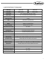
R
User’s
Manual
SPS/E-1306 Series
SPS/E-1507 Series
Electronically Controlled
Pattern Sewing Machine
(Mechanical Part)
SUNSTAR MACHINERY CO., LTD.
1) FOR AT MOST USE WITH EASINESS,
PLEASE CERTAINLY READ THIS MANUAL
BEFORE STARTING USE.
2) KEEP THIS MANUAL IN SAFE PLACE
FOR REFERENCE WHEN THE MACHINE
BREAKS DOWN.
MME-061207
lity
a
u
tQ
Besst Pricevice
Be st Ser
Be
1. Thank you for purchasing our product. Based on the rich expertise and
experience accumulated in industrial sewing machine production, SUNSTAR
will manufacture industrial sewing machines, which deliver more diverse
functions, high performance, powerful operation, enhanced durability, and
more sophisticated design to meet a number of user’s needs.
2. Please read this user’s manual thoroughly before using the machine. Make
sure to properly use the machine to enjoy its full performance.
3. The specifications of the machine are subject to change, aimed to enhance
product performance, without prior notice.
4. This product is designed, manufactured, and sold as an industrial sewing
machine. It should not be used for other than industrial purpose.
R
SUNSTAR MACHINERY CO., LTD.
Contents
1. MACHINE TYPE AND SPECIFICATIONS ............................................................ 6
1.1) Machine type .......................................................................................................... 6
1.2) Specifications of the machine .............................................................................. 7
2. SAFETY RULES ......................................................................................................... 8
2.1) Safety Stickers ....................................................................................................... 8
2.2) Machine Delivery ................................................................................................... 9
2.3) Machine Installation ............................................................................................ 10
2.4) Machine Operation .............................................................................................. 10
2.5) Repair and Maintenance .................................................................................... 11
2.6) Devices for Safety ............................................................................................... 11
2.7) Location of Safety Labels ................................................................................... 12
2.8) Type of Safety Labels ......................................................................................... 12
3. ASSEMBLY ................................................................................................................ 13
3.1) Name of Machine Parts ..................................................................................... 13
4. MACHINE INSTALLATION .................................................................................... 14
4.1) Installation Environment ..................................................................................... 14
4.2) Electricity Environment ....................................................................................... 14
4.3) Table Installation ................................................................................................. 14
4.4) Machine Installation ............................................................................................ 15
4.5) Accessory Installation ......................................................................................... 17
5. PREPARATIONS BEFORE OPERATING THE MACHINE ............................ 19
5.1) How to Supply Oil ................................................................................................ 19
5.2) needle .................................................................................................................. 20
5.3) Thread .................................................................................................................. 21
6. HOW TO REPAIR THE MACHINE ....................................................................... 25
6.1) Adjusting the Height of the Needle Bar ........................................................... 25
6.2) Adjusting the Needle and the Shuttle ............................................................... 25
6.3) Adjustment of Lower Shaft Gear and Oscillating Shaft .................................. 26
6.4) Adjustment of Shuttle Upside Spring Position ................................................. 26
6.5) Adjusting the Height of the Feed Plate ............................................................. 27
6.6) Adjusting the Presser Foot Devices .................................................................. 27
6.7) Adjusting the Parts for the Presser Plate ......................................................... 29
6.8) Adjusting the Parts for Thread Release ........................................................... 29
6.9) Adjusting Parts for the Wiper ............................................................................. 31
6.10) Adjusting the X-Y Parts .................................................................................... 32
6.11) How to Set the Original Point of X-Y ............................................................... 33
6.12) Adjusting the Trimming Parts ........................................................................... 34
4
6.13) Mounting the Direct Motor and Adjsuting Method ......................................... 37
6.14) Oil Supply ........................................................................................................... 37
6.15) Cleaning ............................................................................................................. 40
6.16) Handling of Waste Oil ....................................................................................... 40
7. CAUSES OF BREAK-DOWN AND TROUBLESHOOTING .......................... 41
8. SPS/E-1306(1507)-GS-10 ....................................................................................... 43
8.1) Machine Specifications ....................................................................................... 43
8.2) How to Thread the Upper Thread ..................................................................... 43
9. SPS/E-1306(1507)-HS(GS)-20(21, 22,22-1,23) ................................................. 44
9.1) Machine Specifications ....................................................................................... 44
9.2) Infusion of Pressured Air and Adjustment of Pneumatic Pressure ............... 45
9.3) Attaching the Pressure Plate Sheet and Adjusting the Height of the Slider Base ....... 45
9.4) How to Adjust the Up and Down Movement of the Upper Feed Plate ........... 46
9.5) How to Use the Pedal Switch ............................................................................ 47
9.6) Air System Ciruit Diagrams ................................................................................ 49
10. DRAWING OF TABLE ............................................................................................ 53
10.1) SPS/E-1306(1507) Series ............................................................................... 53
5
1
MACHINE TYPE AND SPECIFICATIONS
1.1) Machine type
SPS / E - 15 07 - H S - 10
SunStar
Pattern
System
Feeding Frame Type
Series
E:Full Closed Pulse Motor Type
Stitch Type
(X)×130mm
Sewing Area
Material Type
(Y)×60mm
Pattern Model
Stitch Type
E:Full Closed Pulse Motor Type
S:Standard Stitch
Sewing Area
Feeding Frame Type
1306:X(130mm), Y(60mm)
1507:X(150mm), Y(70mm)
10 : Motor-type Feed Frame
20 : Pneumatic Monolithic Feeding Frame
21 : Pneumatic Monolithic Feeding Frame with Two
Step Stroke Device
22 : Pneumatic Separately-Driven Feeding Frame
(22-1 : Pneumatic Separately-Driven Feeding Frame
wiht Two Step Stroke Device
23 : Pneumatic Separately-Driven Feeding Frame
with Inverting Clamp Device
Application Sewing Area
G:General Material
H:Heavy Material
6
1.2) SPECIFICATIONS OF THE MACHINE
Series type
SPS/E-1306
SPS/E-1507
Sewing Area
130mm×60mm
150mm×70mm
Sewing Speed
Max. 2,700 spm (Stitch width 3mm or below
Stitch Length
0.1 ~ 12.7mm (Min. limit of resolution: 0.05mm)
Needle
DP×17, DP×5
Needle Bar Stroke
41.2mm
Hook
Semi-Rotary Large Shuttle Hook
Bobbin Case
Bobbin Case for Semi-Rotary Large Shuttle Hook
Bobbin
Bobbin for Large Shuttle Hook
Presser Foot Stroke
Standard 4mm [ 0.5~10mm ]
Lifting Amount of Presser Foot
Max. 20mm
Lifting Amount of Feeding Frame
Max. 25mm
Feeding System
Full Closed Pulse Motor-based Feed
Emergency Stop Function
Available During Sewing Operation
Pattern Select Function
Pattern No. Can be Selected from No.1 to No.999
Memory
CF Card (Floppy Diskette:Option)
Memory Backup
The Working Point is Stored in the Memory when the machine stops Abnormally
2nd Origin Function
Another Origin Point Can be Set by Using Jog Key
Maximum Speed Limit
The Maximum Speed can be Limited from 200 to 2,700 spm
Number of Patterns
CF Card (128 Mbyte : Max. 2100 patterns [up to 20000 stitches/pattern])
Safety Device
Emergency Stop Function, Maximum Speed Limit Function
Main Motor
Direct drive-type 550W AC servo motor
Power Consumption
600VA
Recommended Temperature
5。C ~ 40。C
Recommended Humidity
20% ~ 80%
Power
1ф : 100~240V, 3ф: 200~440V, 50/60Hz
7
2
SAFETY RULES
2.1) Safety Stickers
The safety stickers in this user’s manual are divided into Caution , Danger , and Warning . They indicate that if
the safety rules are not kept, injury or damage to machine might occur as a result.
No.
Name
Description
Caution
If the machine is not properly handled, it may cause injury to users or
physical damage to the machine.
Warning
If the machine is not properly handled, it may cause death or severe
injury to users.
Danger
If the machine is not properly handled, it may cause death or severe
injury to users, and the urgency of the danger is very high.
Caution
Warning
Danger
8
2.2) Machine Delivery
Mark
Description
The machine delivery shall be conducted by the persons who are
knowledgeable about the safety instructions and rules. The following
safety rules must be observed:
2.2.1) Manual delivery
Danger
When the machine is delivered by persons, they shall wear special shoes and tightly
hold the machine on the left and right sides.
2.2.2) Forklift delivery
1) A forklift shall be big enough to endure the weight of the sewing machine and
carry the machine.
2) Use the palette when lifting the machine. Set the center of gravity of the machine
(center of the left and right sides) at the fork arm of the forklift and carefully lift
the machine.
Ban people from
standing under the
machine and remove
obstacles near the
machine.
Warning
Make sure to maintain the balance of the machine when unloading the
machine by using a forklift or crane to prevent the deformation of the
machine or to prevent people from being exposed to danger.
9
2.3) Machine Installation
Depending on the installation environment, function errors, breakdown,
or other physical damage might result. Make sure to meet the following
conditions for machine installation:
Caution
1) The workbench or table where the machine is installed should be durable enough to
endure the weight of the machine (see the name plate).
2) Dust and humidity are the cause of machine pollution and erosion. Please install an air
conditioner and conduct regular maintenance of the machine.
3) Install the machine at the place where it is not exposed to direct sunlight (if the
machine is exposed to direct sunlight for a long time, it may cause discoloration or
deformation).
4) Secure the space around the machine. Place the machine at least 50cm away from the
left, right, and rear walls to secure sufficient space for maintenance activities.
5) Explosion risk : To prevent possible explosion, immediately stop the machine
operation if there are inflammable materials in the air.
6) Lighting : The machine does not offer lighting devices. When necessary, install needed
lighting.
7) Overturn risk : Do not install the machine on the unstable stand or table. If the machine
drops, it may cause injury or severe impact on the machine. If the machine is suddenly
stopped or the external impact is imposed, the machine might be capsized.
2.4) Machine Operation
The machine body is attached with Caution and Warning stickers at
each dangerous part to emphasize safety instructions. With the full
understanding of the safety instructions, make sure to observe the
following during machine operation:
Warning
10
1) Before turning on the power, read this manual thoroughly and have a full
understanding of machine operation.
2) Get properly dressed. Long hair, necklace, bracelet, or wide sleeve might be fed into the
machine during operation. Wear slip-free shoes to prevent slipping on the floor.
3) Check the moving scope of machine before its operation to find out whether the scope
is proper.
4) Keep hands and head away from the machine parts where accidents might occur
(needle, hook, thread take-up lever, pulley, etc.) during operation.
5) Do not remove the safety cover which protects pulley and shaft during machine
operation for user’s safety.
6) Cut the power supply before disassembling the electric box such as the control box,
and double-check that the power switch is“Off.”
7) Make sure that the power switch is“Off”when the upper shaft is manually rotated.
8) Stop the machine when the needle is replaced or when inspecting the machine after
sewing work is done.
9) Make sure to follow the cautions below. Otherwise, physical damage to the machine
such as malfunction and breakdown might result:
- Do not put articles on the S/M table.
- Avoid using a crooked needle or the needle with damaged tip.
- Use the presser foot appropriate to working conditions.
2.5) Repair and Maintenance
When machine repair is needed, it shall be conducted by SunStar A/S
engineers only who have finished the due training course.
1) For cleaning and repair, cut the main power supply. Wait for 4 minutes before starting
maintenance to make the machine completely discharged.
For main shaft motor and X,Y drive box, it takes 10 minutes before they
are completely discharged after the main power is cut.
Danger
Caution
2) Do not modify the machine specifications or parts without substantial consultations with
SunStar. Otherwise, it may threaten safety during machine operation.
3) Use the parts manufactured by SunStar to repair or replace the machine parts during
A/S service.
4) When repairing is completed, re-install all the removed safety covers.
2.6) Devices for Safety
ⓐ
ⓑ
ⓒ
ⓓ
ⓔ
Safety label : It describes cautions during operating the machine.
Thread take-up lever : It prevents from any contact between body and take-up lever.
Motor cover: Prevents any possible accidents while the motor is in motion.
Step motor cover : It prevents from accidents during rotation of step motors.
Label for specification of power : It describes cautions for safety to protect against
electric shock during rotating the motors.
ⓕ Safety plate : It protects eyes against needle breaks.
ⓖ Finger guard : It prevent from contacts between a finger and needle.
Caution
ⓑ
ⓐ
ⓕ
ⓒ
ⓓ
ⓖ
ⓐ
ⓔ
11
2.7) Location of Safety Labels
CAUTION
경 고
Do not operate without finger guard and
safety devices. Before threading, changing
bobbin and needle, cleaning etc. switch off
main switch.
손가락 보호대와 안전장치 없이 작동하지
마십시오.
실, 보빈, 바늘교환시나 청소전에는 반드시
주전원의 스위치를 꺼 주십시오.
WARNING
경 고
Hazardous voltage will cause injury.
Be sure to wait at least 360 seconds
before opening this cover after turn off
main switch and unplug a power cord.
고압 전류에 의해 감전될 수 있으므로 커버를
열 때는 전원을 내리고 전원 플러그를 뽑고 나
서 360초간 기다린 후 여십시오.
2.8) Type of Safety Labels
CAUTION
경 고
Do not operate without finger guard and
safety devices. Before threading, changing
bobbin and needle, cleaning etc. switch
off main switch.
손가락 보호대와 안전장치 없이 작동하지
마십시오.
실, 보빈, 바늘교환시나 청소전에는 반드시
주전원의 스위치를 꺼 주십시오.
Do not operate without finger guard and safety devices. Before
threading, changing bobbin and needle, and cleaning, turn off the
main switch.
WARNING
경 고
Hazardous voltage will cause injury.
Be sure to wait at least 360 seconds
before opening this cover after turn off
main switch and unplug a power cord.
고압 전류에 의해 감전될 수 있으므로 커버를
열 때는 전원을 내리고 전원 플러그를 뽑고 나
서 360초간 기다린 후 여십시오.
12
Hazardous voltage will cause injury.
Be sure to wait at least 360 seconds before opening this cover after
turn off main switch and unplug a power cord.
3
ASSEMBLY
3.1) Name of Machine Parts
3.1.1) Name of Machine Parts
Arm
Emergency Switch
Thread Stand
OP Box
Control Box
Power Switch
Sewing pedal
Upper feed plate pedal
Manual pedal
13
4
Machine Installation
4.1) Installation Environment
1) To prevent accidents stemming from mal-operation, do not use the machine if the voltage is 10% above the rated voltage.
2) To prevent accidents stemming from mal-operation, make sure to check if the air pressure is proper before using
any air pressure devices such as air cylinder.
To guarantee smooth operation of the product, the installation environment shall be prepared as
described in User’
s Manual. Otherwise, unexpected damage might occur to the product.
Caution
3) Proper temperature during machine operation : 0°~ 40°C (32°~ 104°F)
4) Proper temperature during machine storage : -25°~ 55°C (-13°~ 131°F)
5) Humidity : Relative humidity – within 45 ~ 85%
4.2) Electricity Environment
The voltage shall be within 10% of the rated voltage.
Warning
1) Power voltage
- The power voltage shall be within 10% of the rated voltage.
- It is recommended to use the power frequency within +/- 1% of the rated frequency (50/60Hz).
2) Noise of electromagnetic wave
- Do not share the power with the products which have either strong magnetic field or use high frequency. Make
the machine stay away from the products mentioned above.
3) Take care not to spill water and coffee on the machine.
4) Do not drop Control Box and the motor to the floor.
4.3) Table Installation
1) Table fixing
- Insert the shock absorbing rubber into the level adjuster and raise it until the caster freely moves.
- After the table is installed, tighten the nut to fix the level adjuster.
2) Table height adjustment
- Use the bolts attached to the table to adjust the height of the table to make sure that the users can smoothly and
conveniently work.
Bolt
Nut
Level Adjuster
Shock Absorbing
Rubber
14
Caster
To prevent safety accidents, at least two persons shall be assigned to machine installation or machine
delivery.
Caution
4.4) Machine Installation
1) Install the waste oil can support, the oil dish, the
control box, and the power switch on the table.
Oil Dish
Waste Oil Can
Support
Control Box
Power Switch
2) Install the bed cushion rubber and the support
rubber for safety switch to prevent the machine
vibration and noises from occurring.
Safety Switch Rubber
Cushion
Rubber
3) To fix the machine, attach the hinge and the hinge
rubber to the bed, and install them on the table by
using fixing bolts.
Hinge
Fixing Bolt
Hinge Rubber
15
4) Since the machine has not been fully assembled,
take caution to lean the assembled machine on the
floor, and insert and fasten the bolt into the hinge
to completely fix the machine to the table.
Fixing Bolt
To prevent safety accidents, at least two persons shall be assigned to machine installation or machine
delivery.
Caution
5) Install the safety switch and safety switch bracket on
the sewing machine, and then adjust the bracket
location of the safety switch to make sure that the
attached safety switch can properly operate.
Tightening
Screw
Safety Switch
Bracket
Safety Switch
Safety Switch
Supporting Rubber
6) Complete the cable connection between the machine and the control box, and fix the cables under the table as in
the figure (Set the length of the cables when fixing in consideration of the machine’s erection).
Table
16
4.5) Accessory Installation
Motor Cover
4.5.1) Installation of Motor Cover
Fixing Screw
Attach the motor cover to the rear side of the
machine by using four fixing screws (4EA, small
size).
Fixing Screw
4.5.2) Installation of Safety Plate
Attach the safety plate to the head.
Face Plate
Safety Plate
To guarantee safety, make sure to install the safety plate before using the machine.
Caution
4.5.3) Installation of Thread Stand
Assemble the thread stand and install it on the table.
Make adjustment to properly locate the thread stand.
17
4.5.4) Food pedal switch connection
Connect a plug of pedal switch with control box.
Pedal Switch
18
5
PREPARATIONS BEFORE OPERATING THE MACHINE
5.1) How to Supply Oil
1) Check the amount of oil left in the oil tank which is
installed on the arm and supply oil sufficiently.
Be sure to supply oil when operating the machine for the first time or when the machine has not been
used for a long time.
Caution
2) As shown in the picture, move the feed bracket in the
direction of ″A″and supply oil into the bed oil
window through the hole on the bed cover.
3) Supply oil into the hole in the upper part of the arm.
19
4) Open the hook cover and supply oil till the shuttle
race ring is surrounded by oil. Put the hook cover
back on after finishing.
Shuttle Race Ring
Hook Cover
For safety, keep the hook cover covered during operating.
Caution
5) Supply sillicon oil into the sillicon oil tank which is
installed on the right side of the arm.
5.2) needle
5.2.1) Needle Attachment
Unfasten the needle fixing screw on the needle bar.
Then, with the needle groove facing forward, push
the needle until the upper end touches the needle
hole of the needle bar. Fix the needle in with the
needle fixing screw.
Screw
Needle
20
5.3) Thread
5.3.1) Upper thread placement
Hook the upper thread as shown in the following picture after setting the thread take-up lever at the highest
position. As with the needle bar thread guide, hook the thread as shown in picture for heavy materials.(SPS/E1306(1507)-HS)
Picture ①
5.3.2) Lower Thread Placement
Thread Hole
25mm
1) Insert bobbin into bobbin case as shown in the
picture.
2) After setting the lower thread through the crack
of the bobbin case, insert the thread through
thread hole.
3) Adjust the lower thread to hang 25mm out of
thread hole.
Bobbin
Bobbin Case
Insert the bobbin to turn clockwise when seen from behind the bobbin case
Caution
21
5.3.3) How to Take the Bobbin Case On and Off
Hold knob of the bobbin case and push into the
shuttle until a click sound is heard.
Bobbin Case
Handle
Caution
If the bobbin case and the hook are not accurately assembled, thread might be entangled or the
bobbin case might be ejected during machine operation. Make sure that the bobbin case is
completely inserted into the hook before operating the machine.
5.3.4) How to Adjust the Tension of the Upper
Thread and the Lower thread
1) Adjusting the Tension of the Upper Thread
When the tension adjusting nuts ③ and ④, of
thread tension adjusting unit ① and sub-tension
adjusting unit ②, are turned clockwise the upper
thread is tightened. And loosens when turned the
other way around.
②
④
①
③
2) Adjustment of Main Thread Adjusting Device
A. When the tension adjusting nut① for the thread
adjusting device is turned clockwise, the tension
of the upper thread gets stronger. Otherwise, the
tension gets weaker. The thread tension
adjustment can vary depending on sewing fabric,
thread, and number of stitches. Please make the
adjustment in line with the sewing conditions.
B. The thread take-up lever spring's tension can be
adjusted using the groove② at the end of the
thread tension adjusting device shaft. When it is
turned clockwise, the tension of the thread takeup spring gets stronger, and otherwise, it gets
weaker.
Tension Adjusting Nut
3) Adjusting the Tension of the Lower Thread
The lower thread becomes tight when tension
adjusting screw is turned clockwise, as shown in
the picture. When the screw is turned the other
way the lower thread is loosened.
Tension Adjusting
Screw
22
5.3.5) How to Wind the Lower Thread
1) Insert the bobbin into thread winding drive shaft on thread winding base which is installed on the upper top.
2) Operate the machine after sticking the thread winding lever to the bobbin.
3) When the thread winding lever is separated from the bobbin, cut the bobbin thread with thread winding mes.
Thread Winding
Shaft
Bobbin
Blade
Thread Winding Lever
Thread Winding Base
5.3.6) Adjusting the Winding Device
1) To adjust the winding capacity of the bobbin, use
the beginning position of the winding control
plate, and after unfastening the screw, turn the
plate in direction A for large winding capacity
and turn in direction B for small winding
capacity.
Bobbin
Bobbin Winder Adjusting Plate
2) Place the winding drive wheel 0.5mm away from
the hand pulley gear and tighten the screw.
Upper Shaft
Thread Winder
Drive Wheel
0.5mm
23
5.3.7) Adjusting the Upper Thread Detecting
Device
Thread Take-up Spring
Thread
Detecting
Plate
1) Unfasten the thread detecting plate screw with the
thread off the take-up spring and make the takeup lever spring touch the detecting plate. Then,
tighten the screw.
2) Be sure to adjust the detecting plate so the takeup lever spring and the detecting plate will
connect with each other even when the take-up
lever spring stroke changes.
Screw
Be careful not to touch with any other metals except take-up lever spring. If it does, detection may be
failed.
Caution
5.3.8) Adjusting the Height of the Presser Foot
1) Unfasten presser foot screw ① with the needle
bar at the lowest position.
2) Adjust the height so that the presser foot bottom
comes 0.5mm(the thickness of the thread used)
above the sewing material. Then, tighten the
screw.
Caution
①
0.5mm
After adjusting the height of presser foot, confirm the position of wiper.
·Too excessive gap can cause jumping.
·Insufficient gap can cause a failure in thread adjustment.
5.3.9) Adjusting the Hand Pulley Device
1) Tighten the screw after putting the hand pulley
gear and the hand pulley shaft tip in accord.
2) Adjust the clearance of hand pulley gears and
and tighten the screws.
3) Move the bushing in the direction of the arrow to
reduce the backlash between gears and
when the roller is on the end of the pulley
bushing.
Gear
Hand Pulley Bushing
Hand Pulley Shaft
Upper
Shaft
Gear
Roller
24
6
HOW TO REPAIR THE MACHINE
The machine is set to be the best condition at the factory. Do not make any discrete adjustments on
the machine and replace genuine parts approved by the company only.
Warning
6.1) Adjusting the Height of the Needle
Bar
Tightening
Screw
DP×5
When the needle bar is at its lowest position, unfasten
the needle bar holder screw. Adjust the desired height by
making the specified upper carving line fit in with the
needle bar bushing. Then, tighten the needle bar holder
screw back on firmly.
DP×17
#21 and
Below
DP×17
#22 and Above
6.2) Adjusting the Needle and the Shuttle
Needle Bar Lower Bushing
1) Have the lower carving line for the needle that is
applied when the needle bar goes up fit in with the
lower side of the needle bar bushing as shown in the
picture.
DP×5
DP×17
#22 and Above
DP×17
#21 and
Below
2) After unfastening the shuttle drive screw, open the inner hook pressure bar left to right and remove the shuttle
Race ring from the (large) shuttle.
3) Make the shuttle hook point
accord with the center of the needle. And make the needle and the front face of
the shuttle drive connect each other to prevent the needle from curving. Then, tighten the drive screw firmly.
4) After unfastening the (large) shuttle screw, turn the large hook adjustment shaft to the left to right and adjust the
(large) shuttle so that the needle and the shuttle hook point
is 0.05~0.1mm apart from each other.
5) After adjusting the (large) shuttle in place, adjust the rotary direction of the (large) shuttle so the needle and the
(large) shuttle is 7.5mm apart from each other. Then, tighten the (large) shuttle screw.
For safety, make sure all the screws are tightened firmly after adjusting the (large) shuttle.
Caution
0mm
7.5mm
0.05~0.1mm
Inner
Hook
Presser
Bar
Inner
Hook
Presser
Bar
Race Ring
Adjusting Shaft
Tightening Screw for Shuttle (large)
Tightening Screw
Shuttle (large) for Shuttle Driver
25
6.3) Adjustment of Lower Shaft Gear and Oscillating Shaft
- Loosen tightening screws ①, ②
- Rotate the upper shaft and move the oscillating gear in the arrow direction to find the position where the gear
can smoothly operate without any load.
- Attach the oscillating shaft collar (right) to the bed face and fasten the collar screw②.
- Turn the oscillating shaft collar (right) in the arrow direction, while it is closely attached to the bed face , to
find the place where the roll driver can smoothly rotate with the backlash of 0.1mm or below.
Backlash: 0.1mm or below
①
②
Caution
Oscillating Shaft Collar
(right)
1) If the oscillating gear is not properly positioned, the machine may not operate.
2) If the backlash is excessive, the machine might cause increasing noises during operation. If the
backlash is too small, the machine might not operate.
6.4) Adjustment of Shuttle Upside Spring Position
- Disassemble the lower feed plate and the needle plate in order to enable the adjustment of the shuttle upside spring.
- Loosen the tightening screw for the front spring. Vertically move the needle to make its rear end contact the
area. Adjust the shuttle front spring to make the needle center contact
in the middle. When adjustment
completes, fasten the tightening screw.
Tightening
Screw
Tightening Screw
Caution
26
If the area near the shuttle upside spring’s groove is scratched or grows rough, it may cause thread
break and the separation of thread strands. To prevent it, check the status of the shuttle upside
spring.
6.5) Adjusting the Height of the Feed Plate
Tightening
Screw
After unfastening the lifting lever control plate screws
on each side of the feed bracket, raise the control plate
in direction A to lower the upper feed plate and lower
the control plate in direction B to heighten. Tighten the
lifting lever control plate screws back on firmly after
adjusting the height of the upper feed plate.
Feed Bracket
Upper Feed Plate
Caution
Adjust the height of the feed plate and completely fasten each tightening screw.
Due to machine operation, the screws might get loose, causing damage to the machine.
6.6) Adjusting the Presser Foot Devices
1) Have the end of the presser foot drive cam accord
with the carving point center of the upper shaft, and
the line of the cam accord with the carving point.
Tighten screw.
Carving
Point
Tightening Screw
Upper
Shaft
Driving Cam
2) Adjustment of Presser Bar Height
Adjust the end of the presser bar to protrude by
13mm from the pressure bar handle, and fasten the
tightening screw.
13mm
Caution
If the presser foot drive cam is not in the right position, the presser foot may not move vertically in time
and run into the needle bar.
Tightening
Screw
Presser Bar
Holder
Presser Bar
Caution
Fasten joint screw of presser bar with the pressure about 40-45kgf/㎠. If connection pressure is
excessive, it becomes cause of deformation of presser bar and cause trouble to machine operation.
27
3) Presser Foot Origin Setting
a) Turn on the power, and to set the motor base punched mark on the right side of the presser foot motor base①
to meet the punched mark of the presser foot cam shaft②, loosen the tightening screw for the sensor plate③
on the opposite side and adjust the position of the sensor plate④.
Caution
When the presser foot is at the origin, the height of the presser foot is 20mm from the highest point of
the needle bar.
b) Presser Foot Lowest Height Setting
When the presser foot cam reaches the lowest position of the presser foot and the needle bar is at the lowest
position, loosen the nut⑤ and set the presser foot lowest position by turning the stopper bolt⑥.
⑥
①
⑤
④
②
③
4) Adjustment of Presser Foot Stroke
a) Adjustment of Presser Foot Stroke by Adjusting
Presser Foot Driving Cam's Connection Rod
– Loosen the hinge nut for cam connection ①
and push it up. Then, the stroke will rise.
When it is pulled down, the stroke will be
reduced.
Presser Foot Cam Crank
①
Rising Stroke
Hinge Screw
for Cam
Connection
The default value is 4mm when it is released from a factory.
Caution
28
Lowering Stroke
Presser Foot
Driving Cam's
Connection Rod
6.7) Adjusting the Parts for the Presser Plate
1) Make the two arms tightly contact the arm foundation to enable the presser plate arms to press the presser plate
shaft pin ② with equal pressure, and then fasten the tightening screws ⑧.
Caution
The screws may be damaged when the left and right presser plate arms are not set in the same
angle.
2) When the presser plate ① is at the highest position, and when the presser plate shaft pin ② and the presser plate
arm ③ are closely contacted, fix the presser plate connection link A ④ and B ⑤.
③
②
④
①
⑤
⑦
③
⑧
⑥
②
⑧
Then, adjust the position of the presser plate cam ⑥ by set the tightening screw ⑦ perpendicularly.
Caution
6.8) Adjusting the Parts for Thread Release
Tightening Screw
6.8.1) How to Set the Thread Release Notch
Place the notch so that the right side of the slot of the
thread release notch touches circumference of the
notch screw, and then fix with a screw.
Notch
Thread Trimming
Cam
Caution
The remaining amount of thread may not be enough or not be regular and the thread may be
unfastened from the needle if the notch is not set in the right position.
29
6.8.2) How to Set the Thread Release Stopper
1) Remove the thread release return spring.
2) After unfastening the thread release stopper screw, adjust the trimming drive link and the thread release lever
pin 0.3mm apart from each other. Then, attach the arm to the thread release stopper completely.
3) When the thread release stopper is pushed to the right, the space between the trimming drive link and the
thread release lever pin is reduced. And it is enlarged when the stopper is pushed to the left.
4) Hang on the thread release return spring.
Use a tool when removing or attaching the thread delay spring to prevent accidents.
Caution
Thread Release Lever Pin
Thread
Trimming
Driving Link
Return Spring
0.3mm
Thread Release Stopper
Tightening Screw
Widen
Narrow
6.8.3) How to adjust the opening capacity of the thread guide disk
1) Unfasten the thread release adjusting plate screw.
2) Open the thread guide disk by operating the trimming devices.
3) Adjust the opening capacity to 0.6~0.8mm for normal material and 0.8~1mm for heavy material. To increase
the opening capacity, widen the angle between the thread release plate and narrow the angle to reduce the
opening capacity.
4) Tighten the screw after the adjustment.
Caution
If the disk is not opened appropriately, the amount of remaining thread may be not enough or not
regular, and the disk may not be closed completely.
Widen
Narrow
Floating Amount
Tightening Screw
Thread Tension Adjusting
Plate
To Tension Release Link
30
To Thread Tension Adjusting Ass’
y
6.9) Adjusting Parts for the Wiper
6.9.1) Adjusting the Wiper Position
1) Unfasten the wiper rotary shaft collar screw and the wiper crank screw when the needle tip is 19.5mm above
the needle plate
2) Press the wiper rocking link, then adjust the wiper shaft so the wiper and the needle is about 10mm apart from
each other.
3) Tighten the wiper rotary shaft collar screw and the wiper crank screw.
4) Unfasten the wiper screw and adjust the wiper so that the end of the wiper is about 1mm apart from the needle
end. Then, tighten the screw back on firmly.
Caution
If the wiper is not placed in the right position, the wiper may collide with the presser foot or needle
during the operation, and the wiper may not move properly.
Push
Wiper
Oscillator
Link
Tightening Screw for
Wiper Crank
Tightening
Screw for Wiper
Tightening Screw for Wiper
Spinning Shaft Collar
Wiper Shaft
1mm
Needle Plate
10mm
19.5mm
6.9.2) Wiper On/Off Switch
Wiper On/Off Switch
If you want to use the wiper, press the Wiper On/Off
Switch —, if you don’t, press the Wiper
Operating Switch O.
Wiper Off
Wiper On
31
6.10) Adjusting the X-Y Parts
6.10.1) Adjusting the tension of the X-timing Belt
1) Move the race table to the left.
2) Use the tension gauge to adjust the X-tension adjustment bolt so that 800g of load is applied 4mm longer on
the timing belt. Tighten the nut after the tension is adjusted.
Caution
If the timing belt is too tense, the belt may be damaged, and if the belt is too relax, the transfer in
direction X may become difficult.
3) Tighten the X-bracket screw.
Race Table
Belt Tension Gauge
X-Timing Belt
800g
Belt Tension Gauge
Tightening
Screw
Nut
Adjusting
Bolt
X-Timing Belt
4mm
6.10.2) Adjusting the tension of the Y-timing Belt
Use the tension gauge to adjust the Y-tension adjustment bolt so that 1100g of load is applied 3mm away from the
center of the timing belt. Then, tighten the Y-bracket screw.
Caution
If the timing belt is too tense, the belt may be damaged, and if it is too relax, the transfer in direction Y
may become difficult.
3mm
Tightening
Screw
Y-Timing Belt
Belt Tension
Gauge
Adjusting Bolt
32
Y-Timing Belt
1100g
Belt Tension Gauge
6.11) How to Set the Original Point of X-Y
6.11.1) How to set the original point of the X-axis
1) Remove the lower feed plate, X-fixed cover, and transport cover.
2) Place the upper feed plate center in the middle of the X-axis direction.
3) Unfasten the two screws of the X-axis original point detecting sensor supporting plate and have the X-axis
original point detecting plate on the X-Y transfer system placed in the center of the sensor as shown in the
picture. Then, tighten the screw with the driver.
Tightening
Screw
Sensor
Support Plate
Sensor
Origin Detecting
Plate
6.11.2) How to Set the Y-axis Original Point
1) Remove the Y- stepping motor cover.
2) Move the upper feed plate to the middle of the Y-axis direction.
3) Unfasten the screw and place the Y-axis original point detecting plate in the center of the original point
detecting sensor as shown in the figure. Then, tighten the screw with the L wrench.
Origin Detecting
Plate
Sensor
Tightening Screw
Sensor
Support Plate
33
6.12) Adjusting the Trimming Parts
6.12.1) Setting the position of the trimming Cam
Set the upper shaft collar and the trimming cam 2.5mm apart from each other and place the trimming cam where
the trimming cam carving line accords with the upper shaft carving point. Then, tighten screw ①.
Caution
If the trimming cam is not placed in the right position, the trimming operation may not be made
correctly or the machine may be lock.
Thread Trimmer Cam
Carving Line
2.5mm
Carving Point
Upper
Shaft
Upper Shaft
Upper Shaft
①
Collar
6.12.2) How to adjust the link stopper
1) When the needle bar is at the lowest position, push the trimming link in the trimming cam direction within the
moving scope of the trimmer cam. And check whether there is appropriate clearance between the trimming
cam roller and the both ends of the trimmer cam.
2) Make the end of the link stopper screw touch part of the trimming link stick when the trimming cam roller
is inserted into the trimming cam moving part. Then, tighten the nut.
Caution
1) If the clearance between the trimmer cam roller and the both ends of the trimmer cam is inappropriate, bad
trimming might result or the parts might be stuck to each other at the beginning of sewing or upon trimming.
2) If the position of the link stopper screw is inappropriate, return to the origin after trimming might take longer
time or the first stitch might be not tight enough.
Thread Trimming Driving Link
Clearance
Clearance
Thread Trimmer
Cam Roller
Thread Trimmer Cam
Thread Trimmer
Connecting Rod
Link Stopper Screw
Link Stopper Screw
Nut
Thread Trimmer Connecting Rod
34
6.12.3) Setting the trimming shaft in place
1) Unfasten the trimming drive link screw and the trimming shaft collar screw.
2) Make the trimming shaft tip accord with part of the arm.
3) Tighten the screws.
If the position setting is inappropriate, bad trimming or stuck parts might take place.
Caution
Thread Trimmer Cam
Thread Trimming
Driving Link
Thread
Trimmer Shaft
Tightening
Screw
6.12.4) Setting the Link Stopper in Place
1) Unfasten the trimming drive link stopper screw
while trimming is not operated and have the
trimming drive link and the trimming drive link
stopper notch 0.3mm apart from each other.
Tightening
Screw
0.3mm
Thread
Trimmer
Driving
Link
0.3mm
Thread Trimmer Driving
Link Stopper
If the position setting is inappropriate, bad trimming or stuck parts might take place.
Caution
35
6.12.5) Setting the Thread Trimming Solenoid in Place
1) After unfastening the thread trimming solenoid bracket screw, have the trimming shaft and the thread
trimming solenoid rotary link 0.5mm apart from each other and tighten the screw back on.
2) Unfasten the thread trimming solenoid rotary link screw and drive the thread trimming solenoid rotary link
manually to move the trimming shaft collar 6.8mm in the direction of the arrow. Then, tighten the screw back on.
3) Check if the trimming shaft collar returns to its place when the thread trimming solenoid rotary link returns.
Caution
If the position is not set right, the trimming return or the thread delay may be delayed to bring poor
sewing quality.
Tightening
Screw
Thread Trimmer Solenoid Bracket
Thread
Solenoid
Thread Trimming
Rotation Link
Tightening Screw
0.5mm
Thread Trimming
Rotation Link
Thread
Trimmer Shaft
6.8mm
6.12.6) Adjusting the Moving Knife and the Fixed Knife
1) When the needle bar stops at the upper position, use the trimming lever adjustment screw to adjust space A
between the thread separation point of the moving knife and the needle plate hole as indicated in the table.
2) Use the fixed knife screw to adjust space B between the fixed knife and the needle plate cover as indicated in
the table.
3) After the adjustment, check the position of the knife by manual trimming operation.
Trimming may not be operated or there may not be enough remaining thread if the knife is set
inappropriately.
Caution
G
H
Fixed Knife
Needle Plate
Cover
Moving Knift
36
A
4.5mm
5.3mm
B
1~1.2mm
1~1.2mm
6.13) Mounting the Direct Motor and Adjsuting Method
1) When you mount the coupling on the servo-motor, fit the screw No.1 of coupling to the flat surface of the servo
motor shaft and make the clearance between the coupling and servo motor 0.7mm.
2) When you mount the coupling on the upper shaft, fit the screw No.1 of coupling to the flat surface of the upper
shaft and make the clearance between the coupling and upper shaft bushing(R) 2mm.
3) After mounting both couplings, check the positions of each screws to the aligned.
※ If the positions of each screws are not aligned, the needle does not stop normal position.
Screw NO.1
Servo Motor
Rear Upper Shaft Bearing
Upper Shaft
Upper Shaft Rear
Bearing Bushing
(rear)
Flat Surface
Arm
2.3mm Coupling
0.7
6.14) Oil Supply
Caution
1) During machine check or maintenance, please observe the safety rules on machine and electricity.
2) Make sure that the power is off before maintenance work begins.
6.14.1) Regular Check List
1) For the parts which need regular check, conduct cleaning and lubrication and add grease to maintain high
machine performance.
2) Test the tension of each driving belt.
3) Without regular machine check, the following problems might result:
- Abnormal abrasion of the moving parts in a wet condition due to the insufficient lubrication and grease
injection
- Abnormal operation due to dust or foreign materials gathered at the moving parts
Caution
1) If machine damage or mal-operation occurs due to the failure to clean and lubricate the machine
through regular checking, SunStar will not be held liable.
2) Adjust the cleaning cycle depending on the use conditions and environment.
37
6.14.2) Oil Supply
1) Type of Lubricant
No.
Type of Lubricant
Parts Applied
1
S/M oil
Arm, Bed, Hook
2
Silicon oil
Silicon oil supply tank
6.14.3) Oil Supply Method
1) Arm
- Check the remaining oil volume at the oil tank
installed at the arm before supplying oil.
- Fill up the oil tank through the oil outlet at the
upper arm.
Caution
Please lubricate the sewing machine at the first time of using the machine or when the machine
remains unused for a long time.
2) Bed
-Move the feed bracket in the "A" direction and
check the remaining oil volume from the oil
window. Supply sufficient oil through the oil
tank outlet.
38
3) Hook
- Open the hook cover and supply oil to the
extent that the area surrounding the shuttle
race ring is wet with oil. When lubrication
completes, make sure to place back the hook
cover.
Shuttle Race Ring
Hook Cover
To prevent safety accidents, keep the hook cover remain covered during machine operation.
Caution
4) Silicon Oil Tank
- Supply silicon oil to the silicon oil tank installed
on the right side of the arm.
39
6.15) Cleaning
6.15.1) Cleaning Cycle and Method
Caution
1) Make sure to turn “off” the machine power before conducting cleaning.
2) Assemble the parts which are disassembled for cleaning.
No.
Cleaning Area
1
Around hook
2
Thread take-up lever / Thread tension adjusting device
Cleaning Frequency
Everyday
Once a week
Around the moving and fixed blades.
3
Use air to clean the moving and fixed blades under
the needle plate.
Three times a week
6.16) Handling of Waste Oil
When the waste oil can attached to the rear side of the
table is filled to the full, separate and empty the can.
Table
Waste Oil Can
Caution
40
1) When separating the waste oil can, take caution not to drop it to the floor.
2) Just in case for dropping the waste oil can to the floor, place cloth, paper or oil dish on the
floorwhen separating the waste oil can.
7
CAUSES OF BREAK-DOWN AND TROUBLESHOOTING
No.
1
2
3
4
5
Type of Breakdown
Error on operation or
drive of machine
Bad position of
stopping position
Needle bent
Thread is cut
Stitch skipping
Cause
Troubleshooting
Loosing of belt tension and damage on
belt
Adjust the belt tension or exchange it
Fuse shortage for main power or circuit
Check the fuse shortage of main shaft drive
motor in a controller box or exchange it
Deviation from Y and Y limit of feed
bracket
Move the feed bracket to normal place
(inside limit switch)
Slackness of main drive belt
Adjust the belt tension
Wrong position of upper shaft sensor
plate or photo sensor
Adjust the position of upper shaft sensor
plate or exchange the photo sensor
Damage on needle(Bending of needle,
cracks on needle hole or groove, and
abrasion or transformation of needle tip)
Exchange the needle
Wrong installation of needle
Install the needle properly
Contact of needle with shuttle
Adjust the distance properly between a needle and shuttle
Wrong insertion of thread
Insert the thread properly
Wrong installation of needle (Height
of needle or direction of needle )
Reinstall the needle
Damage on needle ( Bending of needle,
cracks on needle hole or groove, and
Exchange the needle
abrasion or transformation of needle tip)
Excessive tension of upper thread and under thread
Adjust the tension
Excessive tension and stroke of take-up
lever spring
Adjust the tension and stroke of take-up lever
spring
Crack on the controlling hole of shuttle
surface spring
Exchange the shuttle surface spring
Use of bending needle
Exchange the needle
Use of improper sized needle compared with using thread
Exchange the needle
Wrong installation of needle
Reinstall of needle
Improper timing for a needle and shuttle
Readjust the timing for a needle and shuttle
Large interval between a needle groove and shuttle point
Readjust the timing for a needle and shuttle
Excessive tension of take-up lever
spring and stroke
Adjust the tension of take-up lever spring and
stroke
41
No.
6
7
8
42
Type of Breakdown
Cause
Bad connection between take-up lever
Ineffective sense of upper spring and detecting plate
thread
Poor quality of thread
tightening
Mistakes of Trimming
Troubleshooting
Clean up the take-up lever spring and
detecting plate. Adjust the tension of take-up
lever spring and connecting condition of
detecting plate
Bad connection of wire with thread
sensor plate
Reconnect the wire with thread sensor plate
Weak tension of upper thread
Adjust the tension of upper thread
Weak tension of under thread
Adjust the tension of under thread
Improper timing of needle and shuttle
Readjust the timing of needle and shuttle
Slackness of exchange tension between
moving mes and fixed mes
Adjust the tension of fixed mes
Groove abrasion on blade of moving mes and fixed mes
Exchange the moving and fixed mes
Wrong position of trimming cam
Readjust the position of trimming cam
8
SPS/E-1306(1507)-GS-10
8.1) Machine Specifications
It is the same as the specification of SPS/B(A)-1306(1507)-HS-10
8.2) How to Thread the Upper Thread
After placing the thread take-up at the highest position thread the thread as indicated in the picture below.
Thread the thread as shown in picture A for the needle bar thread guide.
picture A
43
9
SPS/E-1306(1507)-HS(GS)-20(21, 22,22-1,23)
9.1) Machine Specifications
44
Series type
SPS/E-1306
SPS/E-1507
Sewing Area
130mm×60mm
150mm×70mm
Sewing Speed
Max. 2,700spm (Stitch Length : 3mm or Less)
Stitch Length
0.1 ~ 12.7mm (Min. limit of resolution: 0.05mm)
Needle
DP×17, DP×5
Needle Bar Stroke
41.2mm
Hook
Semi-Rotary Large Shuttle
Bobbin Case
Bobbin Case for Semi-Rotary Large Shuttle Hook
Bobbin
Bobbin for Large Shuttle Hook
Presser Foot Stroke
Standard 4mm [0.5~10mm]
Lifting Amount of Presser Foot
Max. 20mm
Lifting Amount of Feeding Frame
Max. 30mm
Feeding System
Full Closed Pulse Motor-based Feed
Emergency Stop Function
Available During Sewing Operation
Pattern Select Function
Pattern No. can be Selected from No.1 to No.999
Memory
CF Card (Floppy Diskette:Option)
Memory Backup
The Working Point is Stored in the Memory when the Machine Stops Abnormally
2nd Origin Function
Another Origin Point can be Set by Using Jog Key
Maximum Speed Limit
The Maximum Speed can be Limited from 200 to 2,700 spm
Number of Patterns
CF Card (128 Mbyte : Max. 2100 patterns [up to 20000 stitches/pattern] )
Sefety Device
Emergency Stop Function, Maximum Speed Limit Function
Main Motor
Direct Drive 550W AC Servo Motor
Power Consumption
600VA
Recommended Temperature
5。C ~ 40。C
Recommended Humidity
20% ~ 80%
Power
ф : 100~240V, 3ф : 200~440V, 50/60Hz
Air Pressure
4 ~ 4.5 kgf/cm2 (0.39~0.44 Mpa)
9.2) Infusion of Pressured Air and Adjustment of Pneumatic Pressure
For safety, work with the power cut off.
Caution
9.2.1) Connection for Pressured Air
Air Hose
1) Connect air hose to quick joint socket.
2) Contract quick joint socket and quick joint plug .
3) Open finger valve and flow air in. Then, adjust the
air pressure to 0.39~0.44 MPa(4~4.5kgf/cm2).
Quick Joint Socket
Plug
Finger Valve
[Note]
When the finger valve is closed after use, the
remaining air is rejected and the pressure is adjusted
to 0 MPa(0kgf/cm2).
Caution
When the air pressure goes down (under 3kgf/cm2), an error is indicated and the machine operation is
stopped.
9.2.2) How to Adjust the Air Pressure
- Pull the adjustment handle on the upper part of
the filter controller, which is attached to the back
of the table, up as shown in the picture. When the
handle is turned clockwise the pressure goes up
and goes down when the handle is turned in the
opposite direction. Adjust to the appropriate
pressure 0.39~0.44MPa (4~4.5kgf/cm2) indicated
in the pressure gauge, then press and fix the
adjustment handle into its place.
9.3) Attaching the Pressure Plate Sheet
and Adjusting the Height of the Slider
Base
Direction of Face Plate
Presser
Plate
17.8mm
9.3.1) How to attach the pressure plate sheet
- Attach the pressure plate sheet where the slider
base and the pressure plate meet as shown in the
picture.
2mm
2mm
Presser Plate Sheet
45
9.3.2) How to adjust the height of the slider
base
Presser Plate
- Unfasten the slider base screw ① and adjust the
slider base to the appropriate height. Then tighten
the screw ① back on firmly.
Slider Base
①
②
9.3.3) How to adjust the height of link plate B
- Unfasten link plate B screw ② and adjust the
appropriate height. Then tighten the screw ②
back on firmly.
Link B
9.4) How to Adjust the Up and Down Movement of the Upper Feed Plate
9.4.1) SPS/E-1306(1507)-
-20, 22
- When the speed controller ① knob ②, which is attached on the bottom of the table, is turned clockwise, the
speed decreases. When the speed controller knob is turned counter-clock wise, the speed increases. So fasten
the nut ③ after adjusting the appropriate speed.
[ SPS/E-1306(1507)-
-20 ]
[ SPS/E-1306(1507)-
-22 ]
②
②
③
③
①
①
③
9.4.2) SPS/E-1306(1507)-
-21, 22-1
1) When the pressure decrease valve ① knob ②, which is attached on the bottom of the table, is turned clockwise,
the go-up speed of upper feed plate & supporting pressure increase. When the knob is turned counter-clockwise,
the speed and pressure decrease. So fasten the nut ③ after adjusting the appropriate speed and pressure [Fig. ]
2) When the speed controller ④ knob ⑤ is turned clockwise, the come-down speed decrease. When the knob is
turned counter-clockwise, the come-down speed increases. So fasten the nut ⑥ after adjusting the appropriate
speed [Fig. ].
[ Fig.
②
③
]
①
[ Fig.
]
①
⑤
④
Solenoid Valve
[ SPS/E-1306(1507)-
46
-21 ]
[ SPS/E-1306(1507)-
-22-1 ]
⑥
9.5) How to Use the Pedal Switch
9.5.1) SPS/E-1306(1507)-
-20
1) If you step on the right pedal ①, the upper feed plate descends to hold the sewing material.
2) After the upper feed plate descends, if you step on the left pedal ②, the machine starts sewing.
②
9.5.2) SPS/E-1306(1507)-
①
②
①
-21
1) Check the parameter, related to general sewing (function No.60), is set to‘1’. If not, please set the parameter
to 1. Change of parameter related to general sewing.
2) The padal switch has two pedals, the right one ① moves the upper feed plate, the left one ② makes the
sewing machine start.
3) Application
① The right pedal ① has two step switch, if you step on the first step, the upper feed plate descends to the
intermediate position.
② When the right pedal ① is fully stepped, the upper feed plate fully descends to the sewing material. (If you
fully step on the right pedal ① again, the upper feed plate ascends to the initial position.)
③ If you step on the left pedal ②, the machine starts sewing. (If you step off the right pedal ①, the upper
feed plate ascends to the initial position.)
②
①
②
①
②
①
47
9.5.3) SPS/E-1306(1507)-
-22
1) Check the parameter, related to general sewing (function No.60), is set to‘2’. If not, please set the parameter
to‘2’. Change of parameter related to general sewing.
2) The pedal switch has three pedals, the right one ① moves the right upper feed plate, the intermediate one ②
moves the left upper feed plate and the left one ③ makes the sewing machine start.
3) Application
① If you step on the inermediate pedal ①, the right upper feed plate descends to hold the sewing materials.
② When you step on the left pedal ②, the left upper feed plate descends to hold the sewing material.
(When you step on the pedal ② again, the left upper feed plate ascends to the initial position.)
③ When both of the upper feed plates are descended. If you step on the left pedal ③, the machine starts.
③
②
①
9.5.4) SPS/E-1306(1507)-
③
②
①
③
②
①
③
②
①
-22-1
1) Check the parameter, related to general sewing (function No.60) is set to‘5’. If not please set the parameter to
‘5’. Change of parameter related to general sewing.
2) The pedal switch has three pedals, the right one ① moves the right upper feed plate, the intermediate one ②
moves the left upper feed plate and the left one ③ makes the sewing machine start.
3) Application
① The inter mediate pedal ② has two step switch, if you step on the first step, the left upper feed plate
descends to the inermediate position.
② When the inermediate pedal ② is fully stepped, the left upper feed plate fully descends to the sewing
material. (If you step off the pedal ①, the left upper feed plate ascends to the initial positon.)
③ When you step on the right pedal ①, the right upper feed plate descends to hold the sewing material.
(If you step on the right pedal again, the right upper feed plate ascends to the initial position)
④ When both of the upper feed plates are descended, if you step on the left pedal ③, the machine starts.
③
48
②
①
③
②
①
③
②
①
③
②
①
9.6) Air System Ciruit Diagrams
9.6.1) SPS/E-1306(1507)-HS-20
49
9.6.2) SPS/E-1306(1507)-HS-21
50
9.6.3) SPS/E-1306(1507)-HS-22
51
9.6.4) SPS/E-1306(1507)-HS-22-1
52
10
DRAWING OF TABLE
10.1) SPS/E-1306(1507) Series
53