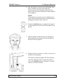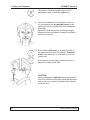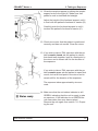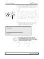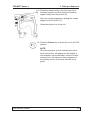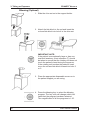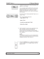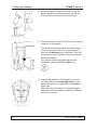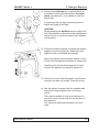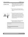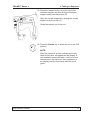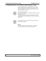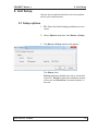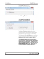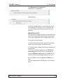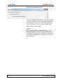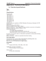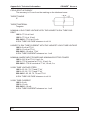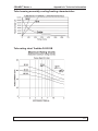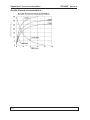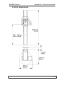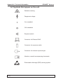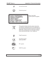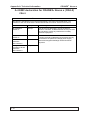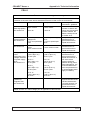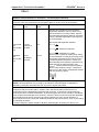
1
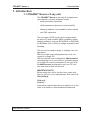
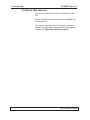
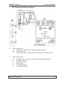
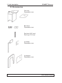
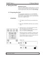
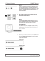
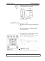
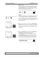
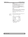
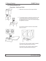
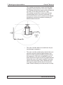
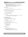
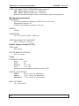
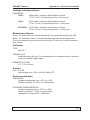
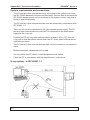
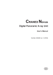
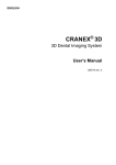
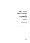
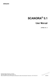
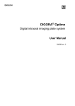
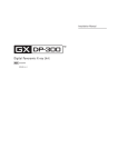
ENGLISH CRANEX® Novus e Digital Panoramic X-ray Unit User Manual 208898 ver. 2 (2012-11) CRANEX® Novus e Contents CRANEX® Novus e Digital Panoramic X-ray Unit User Manual Medical Device Directive 93/42/EEC Number 208898 ver. 2 (2012-11) Original approved English language version Manufactured by SOREDEX, PaloDEX Group Oy Nahkelantie 160, Tuusula P.O. BOX 148 FI-04301 Tuusula, Finland Tel. + 358 (0)10 270 2000 Fax. + 358 9 701 5261 User Manual 208898 iii Contents CRANEX® Novus e SOREDEX® / CRANEX® / DIGORA® / SCANORA® are registered trademarks of SOREDEX. SOREDEX endeavours to produce product documentation that is accurate and up to date. However, our policy of continual product development may result in changes to products that are not reflected in the product documentation. Therefore, this document should not be regarded as an infallible guide to current product specifications. SOREDEX maintains the right to make changes and alterations without prior notice. iv User Manual 208898 CRANEX® Novus e Contents Contents 1. Introduction ........................................................................................................ 1 1.1 CRANEX® Novus e X-ray unit........................................................................ 1 1.2 About this manual........................................................................................... 2 2. Unit description.................................................................................................. 3 2.1 Main parts...................................................................................................... 3 2.2 Control panels and keys................................................................................. 5 2.3 Accessories.................................................................................................... 6 3. Using the Unit..................................................................................................... 7 3.1 Preparing the Unit.......................................................................................... 7 SCANORA®.................................................................................................... 7 DIGORA® for Windows (not in USA).............................................................. 9 3.2 Taking Exposures......................................................................................... 12 Panoramic - Adult and Child........................................................................ 12 Temporomandibular Joint (TMJ).................................................................. 20 Bitewing (Optional)....................................................................................... 26 4. Operating the unit without generating x-rays................................................ 32 5. Unit Setup.......................................................................................................... 33 5.1 Setup options............................................................................................... 33 5.2 Image Preview (DIGORA® for Windows only).............................................. 37 6. Troubleshooting and Maintenance................................................................. 39 6.1 Error messages and symbols....................................................................... 39 Error symbols............................................................................................... 40 User errors................................................................................................... 41 System errors............................................................................................... 41 6.2 Care and Maintenance ................................................................................ 43 Cleaning and disinfecting the unit................................................................ 43 Surfaces that the patient touches..................................................................................... 43 Unit surfaces..................................................................................................................... 43 Positioning mirror.............................................................................................................. 43 Touch screen control panel............................................................................................... 43 Correct operation of the unit........................................................................ 44 Yearly maintenance...................................................................................... 45 7. Warnings and precautions.............................................................................. 46 7.1 General warnings......................................................................................... 46 7.2 User / patient warnings................................................................................ 47 8. Disposal............................................................................................................ 50 Appendix A. Technical Information....................................................................A-1 User Manual 208898 v Contents CRANEX® Novus e vi User Manual 208898 CRANEX® Novus e 1. Introduction 1. Introduction 1.1 CRANEX® Novus e X-ray unit The CRANEX® Novus e (the unit) is a digital panoramic dental x-ray unit designed to take: - adult panoramic exposures, - child panoramic exposures (reduced width) - bitewing (optional, not available in all countries) - and TMJ exposures The unit uses a CCD sensor as the image receptor and a PC with suitable (MDD compliant) dental imaging software, such as SCANORA® or DIGORA® for Windows (not in USA), for image acquisition and handling. The unit can be used in single or multiple user configurations. With the single user configuration the unit is connected to a single PC. With the multiple user configuration (Multiconnect activated) the unit is connected to a network where up to eight PCs can be connected to the unit. With the Multiconnect configuration only one PC at a time can reserve and use the unit. IMPORTANT NOTE: Before using the unit for the first time, make sure that it is set up to your requirements. See section 5. Unit Settings. USA only Caution: Federal law restricts this device to sale by or on the order of a dentist or other qualified professional User Manual 208898 1 1. Introduction CRANEX® Novus e 1.2 About this manual This manual describes how to use and set up the unit. Please read these instructions carefully before operating the unit. Also, before operating the unit, please read and observe the warnings and precautions that appear in section 7. Warnings and Precautions. 2 User Manual 208898 CRANEX® Novus e 2. Unit description 2. Unit description 2.1 Main parts 1. Exposure warning light 2. Emergency stop button (Press to stop, rotate to release) 3. Exposure switch 4. On / off switch (rear of column) 5.Column 6.Sensor 7.Tubehead (Tubehead + sensor = Rotating unit) 8. PC with MDD compliant imaging software User manual 208898 3 2. Unit description CRANEX® Novus e 9. Patient positioning mirror 10.Frankfort light 11.Midsaggital light 12.Focal trough light 13.Head support 14.Patient handles 15.Chin support A. Chin rest and bite block B. Chin rest and lip holder C. Lip support 4 User manual 208898 CRANEX® Novus e 2. Unit description 2.2 Control panels and keys 16. Side control panel A. Lights key - switches the postioning lights on and off. B. Up / down keys C. Return key, drives rotating unit to the patient in/out position (PIO) 17. Main control panel D. Program keys - adult pan, child pan, TMJ, bitewing (optional) E. kV selection keys F. Exposure values G. Service key H. Test exposure key I. Unit status indicator User manual 208898 5 2. Unit description CRANEX® Novus e 2.3 Accessories Chin rest Disposable cover Bite block Disposable cover Rod short (62.5 mm) Rod long (72.5 mm) Lip holder Disposable cover Lip support Disposable cover 6 User manual 208898 CRANEX® Novus e 3. Using the Unit 3. Taking an Exposure IMPORTANT NOTE: If the unit is being used for the first time or if you are using the unit for the first time check that it is set up to your requirements. See section 5. Unit Settings. 3.1 Preparing the Unit The preparation steps below are for SCANORA® and DIGORA® for Windows. If you are using some other dental imaging software refer to the documentation that is supplied with it. SCANORA® 1. PC: Switch on the PC that is connected to the unit. 2. PC: Open SCANORA® and then open a patient card. 3. Switch the unit on. The on/off switch is at the rear of the column near the base. The unit display will come on and the unit will carry out a self test (Starting up). When the self test is complete a question mark (?) will appear next to the unit status indicator. This indicates that you need to reserve the unit before you can take an exposure. Single user: Multiple users: User manual 208898 7 3. Taking an Exposure CRANEX® Novus e NOTE: If the no connection symbol (X) appears next to the unit status indictor, it indicates that there is no connection between the unit and the PC. See section “Troubleshooting and Maintenance” for more information. 4. PC: Press the device icon to reserve the unit and enable image capture. NOTE: If a message appears stating that the unit is in use it indicates that the unit has been reserved by another user. Wait until the unit is free. INFORMATION: The status of the unit, available, ready or busy can be seen in the status field at the bottom of the PC display. 5. When the unit status indicator turns GREEN and the text Status ready appears the unit is ready to take an exposure. Single user: Multiple users: 8 User manual 208898 CRANEX® Novus e 3. Taking an Exposure 6. Press the Return key to drive the rotating unit to the Patient In/Out (PIO) position. DIGORA® for Windows (not in USA) 1. PC: Switch on the PC that is connected to the unit. 2. PC: Open DIGORA® for Windows and then open a patient card. 3. Switch the unit on. The on/off switch is at the rear of the column near the base. The unit display will come on and the unit will carry out a self test (Starting up). Single user: When the self test is complete the unit status indicator will turn GREEN and the text Status ready will appear. The unit can now be used to take an exposure. Go to step 6 to complete unit preparation. User manual 208898 9 3. Taking an Exposure CRANEX® Novus e Multiple users When the self test is complete a question mark (?) will appear next to the unit status indicator. This indicates that you need to reserve the unit before you can take an exposure. NOTE: If the no connection symbol (X) appears next to the unit status indictor, it indicates that there is no connection between the unit and the PC. See section “Troubleshooting and Maintenance” for more information. 4. PC: To reserve the unit click the GREEN Multiconnect icon, which is in the bottom right-hand corner of the PC display. The Connect window will appear. 5. PC: In the Connect window click the Reserve the device button to reserve scanner. The Connect window will disappear and the GREEN Multiconnect icon will start to flash. This indicates that you have now reserved the unit and it is now ready to take an exposure. 10 User manual 208898 CRANEX® Novus e 3. Taking an Exposure NOTE: If the Multiconnect icon is YELLOW, it indicates that the unit has been reserved by someone else. Wait until the unit is free. If you wish to know who has reserved the unit, place the cursor on the Multiconnect icon (while yellow) and a message showing who has reserved the unit will appear. NOTE: If the multiconnect icon is GRAY, it indicates that the unit has not been switched on or is just starting up and is not yet ready for use. Switch the unit on and / or wait until the unit is ready for use. 6. Press the Return key to drive the rotating unit to the Patient In/Out (PIO) position. User manual 208898 11 3. Taking an Exposure CRANEX® Novus e 3.2 Taking Exposures Panoramic - Adult and Child 1. Slide the chin rest on to the support holder. 2. For dentate patients, attach the bite block to the rod and then insert the rod and bite block into the appropriate hole in the chin rest according to the patient’s occlusion. For normal occlusion insert the rod and bite block into hole 2. If the patient’s teeth protrude (angled outward), insert the rod and bite block into hole 1. If the patient’s teeth retrude (angled inward), insert the rod and bite block into hole 3. 12 User manual 208898 CRANEX® Novus e 3. Taking an Exposure For edentulous patients use the lip holder and insert it into the round hole at the rear of the chin rest. 3. Place the appropriate disposable covers on to the patient support you are using. 4. Press the appropriate panoramic program key to select the panoramic program you require, adult or child. The key color will change which indicates that the program has been selected. The magnification of all the programs is 1.25. Adult Child 5. A default kV value for the selected program will appear on the display. User manual 208898 13 3. Taking an Exposure CRANEX® Novus e If you consider that the default kV value for the program selected is not correct for the patient being examined select a different kV value based on the patient’s size, age and estimated bone density. To change the kV value press the kV plus (+) or minus (-) key. The recommended values are: - Large Adult, 77 kV - Adult, 73 kV - Juvenile or small adult, 70 kV - Child, 63 or 66 kV 6. Ask the patient to remove any spectacles, dentures, jewellery and hair clips and pins. Place a protective lead apron around the patient’s neck to protect the patient’s thyroid gland from radiation. NOTE: If the patient is nervous, you can reassure him/ her by demonstrating how the unit works before taking the exposure. See section 4. 7. Press the Up/Down keys to adjust the height of the chin support so it is slightly higher than the patient’s chin. 14 User manual 208898 CRANEX® Novus e 3. Taking an Exposure 8. If the patient is dentate ask the patient to step into the unit, grasp the patient handles, place his/her chin on the chin rest and bite the notches in the bite block. If the patient is edentulous ask the patient to step into the unit, grasp the patient handles and press their top lip against the lip holder. 9. Press the mirror to open it so that you can see a reflection of the patient. The patient positioning lights will automatically come on when the mirror is opened or when one of the Up/Down keys is pressed. They will remain on for two minutes or until the exposure button is pressed. The Patient Positioning lights can also be switched on and off with the Lights key. User manual 208898 15 3. Taking an Exposure CRANEX® Novus e 10.Look at the reflection of the patient in the mirror and position the midsagittal plane of the patient so that it coincides with the midsagittal plane light. Make sure that the patient is looking straight ahead and that the patient’s head is not tilted or turned to one side. 11.Press either Up/Down key to adjust the tilt of the patient’s head until the patient’s Frankfort plane coincides with, or is parallel to, the horizontal light. If necessary use the light positioning knob to adjust the height of the light. CAUTION: When pressing the Up/Down keys to adjust the tilt of the patient’s head make small adjustments only so as not to cause the patient any distress or discomfort. 12.The focal trough light indicates the center of the focal trough which is 10 mm wide at the front. Make sure that the roots of the front incisors are located within the focal trough and are on the same vertical plane. 16 User manual 208898 CRANEX® Novus e 3. Taking an Exposure If the roots of the front incisors are not on the same vertical plane adjust the tilt of the patient’s head until they are. If the roots of the front incisors are on the same vertical plane but not within the focal trough reposition the patient by moving the rod and bite block backwards or forwards. 13.Close the temple supports by sliding the temple support knob to the right (A). Make sure that patient’s neck is stretched and straight. Adjust the height of the forehead support until it is level with the patient’s forehead or nasion (B). Carefully push the forehead support in until it touches the patient’s forehead or nasion (C). User manual 208898 17 3. Taking an Exposure CRANEX® Novus e 14.Check once more that the patient is positioned correctly and has not moved. Close the mirror. 15.Ask the patient to press their lips together and press their tongue against the roof of their mouth. Then ask the patient to look at a fixed point in the mirror and to remain still for the duration of the exposure. The exposure takes approximately nine seconds. 16. Make sure that the unit status indicator is still GREEN, indicating that the unit is ready to take an exposure. If the indicator is not GREEN the unit reservation time may have expired. Reserve the unit again, see section “3.1 Preparing the unit”. 17.Move at least two metres away from the unit and protect yourself from radiation. Make sure that you can see and hear the patient during the exposure. 18.Press and hold down the exposure button for the duration of the exposure. The exposure starts when you hear the exposure warning signal and the exposure warning indicator (control panel) and light (side of the unit) come on. The rotating unit will rotate around the patient’s head and take the exposure. When the exposure warning signal and rotating unit stop, the exposure has been taken. 18 User manual 208898 CRANEX® Novus e 3. Taking an Exposure 19. PC: After the exposure has been taken a progress bar will appear. This indicates that the image is being transferred to the PC. 20.Press the release button (A) at the top of the forehead support and then slide the forehead support away from the patient (B). Open the temple supports by sliding the temple support knob to the left (C). Guide the patient out of the unit. 21.Press the Return key to drive the unit to the PIO position. NOTE: After the exposure, a timer indicating the tubehead cooling time will appear on the display. A new exposure cannot be taken until the counter reaches zero, the exposure time reappears on the display and the unit status indicator turns green. User manual 208898 19 3. Taking an Exposure CRANEX® Novus e Temporomandibular Joint (TMJ) 1. Slide the lip support on to the support holder. Use the slot nearest the mirror for patients with large skulls and the slot furthest away from the mirror for patient with small skulls. 2. Place the disposable cover on to the lip support. 3. Press the TMJ key to select TMJ program. The key color will change which indicates that the program has been selected. The magnification is 1.25. 4. A default kV value for the selected program will appear on the display. If you consider that the default kV value is not correct for the patient being examined select a different kV value based on the patient’s size, age and estimated bone density. To change the kV value press the kV plus (+) or minus (-) key. The recommended values are: - Large Adult - 77 kV - Adult - 73 kV - Juvenile or small adult - 70 kV - Child - 63 or 66 kV 20 User manual 208898 CRANEX® Novus e 3. Taking an Exposure 5. Ask the patient to remove any spectacles, dentures, jewellery and hair clips and pins. Place a protective lead apron around the patient’s neck to protect the patient’s thyroid gland from radiation. NOTE: If the patient is nervous you can reassure him/ her by demonstrating how the unit works before taking the exposure. See section 4. 6. Press the Up/Down keys to adjust the height of the lip support so it is level with the patient’s upper lip. 7. Ask the patient to step into the unit, grasp the patient handles and press their top lip against the top of the lip support. 8. Press the mirror to open it so that you can see a reflection of the patient. The patient positioning lights will automatically come on when the mirror is opened or when one of the Up/Down keys is pressed. They will remain on for two minutes. User manual 208898 21 3. Taking an Exposure CRANEX® Novus e The Patient Positioning lights can also be switched on and off with the Lights key. 9. Look at the reflection of the patient in the mirror and position the midsagittal plane of the patient so that it coincides with the midsagittal plane light. Make sure that the patient is looking straight ahead and that the patient’s head is not tilted or turned to one side. 10.Press either Up/Down key to adjust the tilt of the patient’s head until the patient’s Frankfort plane coincides with, or is parallel to, the horizontal light. If necessary use the light positioning knob to adjust the height of the light. CAUTION: When pressing the Up/Down keys to adjust the tilt of the patient’s head make small adjustments only so as not to cause the patient any distress or discomfort. 22 User manual 208898 CRANEX® Novus e 3. Taking an Exposure 11.Close the temple supports by sliding the temple support knob to the right (A). Make sure that patient’s neck is stretched and straight. Adjust the height of the forehead support until it is level with the patient’s forehead or nasion (B). Carefully push the forehead support in until it touches the patient’s forehead or nasion (C). 12.Check once more that the patient is positioned correctly and has not moved. Close the mirror. 13.If you wish to take a TMJ exposure with the patient’s mouth closed ask the patient to clench their back teeth together, look at a fixed point in the mirror and to remain still for the duration of the exposure. If you wish to take a TMJ exposure with the patient’s mouth open, ask the patient to open their mouth, look at a fixed point in the mirror and to remain still for the duration of the exposure. The exposure takes approximately nine seconds. 14. Make sure that the unit status indicator is still GREEN, indicating that the unit is ready to take an exposure. If the indicator is not GREEN the unit reservation time may have expired. Reserve the unit again, see section “3.1 Preparing the unit”. User manual 208898 23 3. Taking an Exposure CRANEX® Novus e 15.Move at least two metres from the unit and protect yourself from radiation. Make sure that you can see and hear the patient during the exposure. 16.Press and hold down the exposure button for the duration of the exposure. The exposure starts when you hear the exposure warning signal and the exposure warning indicator (control panel) and light (side of the unit) come on. The rotating unit will rotate around the patient’s head and take the exposure. When the exposure warning signal and rotating unit stop, the exposure has been taken. 17.PC: After the exposure has been taken a progress bar will appear. This indicates that the image is being transferred to the PC. 18.If you wish to take a second TMJ exposure, press the Return key to drive the unit back to the PIO position, and then reposition the patient for the second exposure, step 13. Take the second exposure in the same way as described in steps 14 and 15. 24 User manual 208898 CRANEX® Novus e 3. Taking an Exposure 19.Press the release button (A) at the top of the forehead support and then slide the forehead support away from the patient (B). Open the temple supports by sliding the temple support knob to the left (C). Guide the patient out of the unit. 20.Press the Return key to drive the unit to the PIO position. NOTE: After the exposure, a timer indicating the tubehead cooling time will appear on the display. A new exposure cannot be taken until the counter reaches zero, the exposure time reappears on the display and the unit status indicator turns green. User manual 208898 25 3. Taking an Exposure CRANEX® Novus e Bitewing (Optional) 1. Slide the chin rest on to the support holder. 2. Attach the bite block to the rod and insert the rod and bite block into hole 4 in the chin rest. IMPORTANT NOTE: If the patient is exceptionally large or has unusual skull anatomy, a test exposure (T) should be taken to ensure that the rotating unit does not touch the patient’s head during the exposure. If the rotating unit touches the patient’s head, move the rod and bite block forward into hole 3 or 2. 3. Place the appropriate disposable covers on to the patient support you are using. 4. Press the bitewing key to select the bitewing program. The key color will change which indicates that the program has been selected. The magnification of all the programs is 1.25. 26 User manual 208898 CRANEX® Novus e 3. Taking an Exposure 5. A default kV value for the selected program will appear on the display. If you consider that the default kV value for the program selected is not correct for the patient being examined select a different kV value based on the patient’s size, age and estimated bone density. To change the kV value press the kV plus (+) or minus (-) key. The recommended values are: - Large Adult, 77 kV - Adult, 73 kV - Juvenile or small adult, 70 kV - Child, 63 or 66 kV 6. Ask the patient to remove any spectacles, dentures, jewellery and hair clips and pins. Place a protective lead apron around the patient’s neck to protect the patient’s thyroid gland from radiation. NOTE: If the patient is nervous, you can reassure him/ her by demonstrating how the unit works before taking the exposure. See section 4. 7. Press the Up/Down keys to adjust the height of the chin support so it is slightly higher than the patient’s chin. User manual 208898 27 3. Taking an Exposure CRANEX® Novus e 8. Ask the patient to step into the unit, grasp the patient handles, place his/her chin on the chin rest and bite the notches in the bite block. 9. Press the mirror to open it so that you can see a reflection of the patient. The patient positioning lights will automatically come on when the mirror is opened or when one of the Up/Down keys is pressed. They will remain on for two minutes or until the exposure button is pressed. The Patient Positioning lights can also be switched on and off with the Lights key. 10.Look at the reflection of the patient in the mirror and position the midsagittal plane of the patient so that it coincides with the midsagittal plane light. Make sure that the patient is looking straight ahead and that the patient’s head is not tilted or turned to one side. 28 User manual 208898 CRANEX® Novus e 3. Taking an Exposure 11.Press either Up/Down key to adjust the tilt of the patient’s head until the patient’s Occlusal plane coincides with, or is parallel to, the horizontal light. If necessary use the light positioning knob to adjust the height of the light. CAUTION: When pressing the Up/Down keys to adjust the tilt of the patient’s head make small adjustments only so as not to cause the patient any distress or discomfort. 12.Close the temple supports by sliding the temple support knob to the right (A). Make sure that patient’s neck is stretched and straight. Adjust the height of the forehead support until it is level with the patient’s forehead or nasion (B). Carefully push the forehead support in until it touches the patient’s forehead or nasion (C). 13.Check once more that the patient is positioned correctly and has not moved. Close the mirror. 14.Ask the patient to press their lips together and press their tongue against the roof of their mouth. Then ask the patient to look at a fixed point in the mirror and to remain still for the duration of the exposure. The exposure takes approximately nine seconds. User manual 208898 29 3. Taking an Exposure CRANEX® Novus e 15. Make sure that the unit status indicator is still GREEN, indicating that the unit is ready to take an exposure. If the indicator is not GREEN the unit reservation time may have expired. Reserve the unit again, see section “3.1 Preparing the unit”. 16.Move at least two metres away from the unit and protect yourself from radiation. Make sure that you can see and hear the patient during the exposure. 17.Press and hold down the exposure button for the duration of the exposure. The exposure starts when you hear the exposure warning signal and the exposure warning indicator (control panel) and light (side of the unit) come on. The rotating unit will rotate around the patient’s head and take the exposure. When the exposure warning signal and rotating unit stop, the exposure has been taken. 18. PC: After the exposure has been taken a progress bar will appear. This indicates that the image is being transferred to the PC. 30 User manual 208898 CRANEX® Novus e 3. Taking an Exposure 19.Press the release button (A) at the top of the forehead support and then slide the forehead support away from the patient (B). Open the temple supports by sliding the temple support knob to the left (C). Guide the patient out of the unit. 20.Press the Return key to drive the unit to the PIO position. NOTE: After the exposure, a timer indicating the tubehead cooling time will appear on the display. A new exposure cannot be taken until the counter reaches zero, the exposure time reappears on the display and the unit status indicator turns green. User manual 208898 31 4. Operating the unit without x-rays CRANEX® Novus e 4. Operating the unit without generating x-rays In some situations, for example with nervous patients or patients with unusual anatomy, you may wish to operate the unit without generating x-rays before taking an exposure. Press the T key (Test) The key will change color and the kV and mA values will become zero. The exposure switch can now be pressed to demonstrate how the unit operates without x-rays being generated. Press the T key a second time to return to the normal exposure mode. NOTE: After switching the unit off and then on again the unit returns to the normal (exposure) mode. 32 User manual 208898 CRANEX® Novus e 5. Unit Setup 5. Unit Setup Various set-up options allow the unit to be customized to your requirements 5.1 Setup options 1. PC: Open the dental imaging software you are using. 2.Select Options and then click Novus e Setup. 3.The Novus e Setup window will appear. The Status field: Device indicates whether the unit is connected to the PC. Version: shows the software version of the unit and Serial No: the serial number of the unit. User manual 208898 33 5. Unit Setup CRANEX® Novus e The Image Capturing field (DIGORA® for Windows only) The Show Image Preview check box, see section 5.2 Image Preview. The Image Processing field (DIGORA® for Windows only) The Noise Filtering check box should normally be selected. Noise filtering make images smoother when they are taken at low doses. The Automatic Density Adjustment check box should normally be selected. Automatic density adjustment evens out the grayscale values. The Sharpen Filtering check box should normally be selected. When selected it adds default sharpening to all new images. The default value can be changed by entering a new value into the Sharpen Matrix size edit box. Values from 0 to 25 can be entered. The factory set value is 7. 34 User manual 208898 CRANEX® Novus e 5. Unit Setup The Retrieve Last Image field: (DIGORA® for Windows) (SCANORA®) If the last image taken is not transferred to the PC because of a network, PC or software failure, the image can be retrieved from the unit memory. IMPORTANT NOTE The last taken image can only be retrieved if the unit is left on after the last exposure was taken. If the unit is switched off the image will be lost. To retrieve the last image: i. Correct the problem that caused the network failure, and then reopen the patient card. ii. The last taken image should automatically be transferred. If it is not, click the check box in the Retrieve Last Image field (DIGORA® for Windows) or click the Retrieve now button (SCANORA®) to retrieve the last read image taken by the unit. iii. Click OK to close the Novus e Setup window. The last image taken will appear on the patient card. User manual 208898 35 5. Unit Setup CRANEX® Novus e Device Serial Number field: Click the Add serial number ... check box and the serial number of the unit will be added to all new images. The serial number will appear in the top left-hand corner and the bottom righthand corner of the image. NOTE: If you select Enable image marking in DfW (General Setup / Image / Image marking) do not select the left top or right bottom options as the image marking text will appear on top of the serial number. 36 User manual 208898 CRANEX® Novus e 5. Unit Setup 5.2 Image Preview (DIGORA® for Windows only) The Image Preview feature allows an image to be adjusted BEFORE it is saved. The adjustments will be applied to the open image only or to ALL subsequent images. CAUTION: Adjustments made to images CANNOT be undone after the adjustments have been saved. If you wish to “undo” the adjustments retrieve the original image click Retrieve Last Image. 1. PC: In the Novus e Setup window click the Show Image Preview check box. 2. Take an exposure. 3. PC: The Image Preview window will automatically appear. To activate image adjustment, click the Density Adjustment and Sharpen filter check boxes. The Image Quality Controls will become active and the image can be adjusted. CURRENT IMAGE ONLY Click OK to apply the adjustments to the image in the Image Preview window ONLY. CURRENT AND ALL SUBSEQUENT IMAGES Click the Edit Quality Presets button. The Set Image Quality Presets window will appear. The Get from Preview window radio button will be active. Click OK to accept the image adjustments you have made. The Image Preview window will reappear. Click OK to apply adjustments to the current image and ALL subsequent images. User manual 208898 37 5. Unit Setup CRANEX® Novus e NOTE: If you wish to have the factory default settings click the Factory defaults radio button. The Marking field These tools allow you to add text and numbers to an image. 38 User manual 208898 CRANEX® Novus e 6. Troubleshooting and Maintenance 6. Troubleshooting and Maintenance 6.1 Error messages and symbols If the unit is not used correctly or the unit malfunctions an error message or symbol will appear on the unit display. There are three groups of error message: - Error symbols The symbol will clear when the problem is corrected. - H, user errors - E (Error), exposure errors, these occur during exposure. These appear on the error message display. Touch the arrow key to clear the error message and return to the main display. NOTE: If the arrow does not appear on the error message display you will have to wait for the error to clear automatically. User manual 208898 39 6. Troubleshooting and Maintenance CRANEX® Novus e Error symbols REASON i. The PC connected to the unit is not on. ii. The dental imaging software in the PC is not open. iii. The cable connecting the unit to the PC is disconnected or damaged. iv. The IP address is not set correctly. SOLUTION i. Switch the PC on. ii. Open the dental imaging software. iii. Reconnect the cable. If damaged, contact service. iv. Reconfigure the IP address. REASON The emergency stop button is pressed down in the STOP position. SOLUTION Rotate and release the emergency stop button. The error symbol will clear. 40 User manual 208898 CRANEX® Novus e 6. Troubleshooting and Maintenance User errors H1 REASON The exposure button was released during an exposure. SOLUTION Clear the error message and check if the attempted exposure is sufficient for the diagnostic task. If it is not, take a new exposure. If the exposure failed while the exposure button was still being pressed, check the exposure switch by taking a test exposure without patient to see if the exposure button is defective or not. If the same problem occurs again, contact service. System errors E4 REASON Tubehead too hot or too cold. SOLUTION When the error message automatically clears the tubehead has reached the correct operating temperature. In normal conditions this will take about 30 minutes for the tubehead to reach the correct temperature. If the error message does not disappear within a reasonable amount of time, contact service. E5 REASON Line voltage not within limits. SOLUTION If the error message reappears it indicates that the voltage is not within limits. The error message will automatically clear when the voltage returns to the correct level. If the error message keeps on appearing or does not disappear within a reasonable amount of time, contact service. User manual 208898 41 6. Troubleshooting and Maintenance CRANEX® Novus e E19 REASON Exposure switch stuck down during unit start. SOLUTION Switch the unit off and check that the exposure switch is not stuck in the exposure position. Switch the unit on again. If the message reappears, contact service. E21 REASON Patient positioning mirror is open. SOLUTION Close the patient positioning mirror. Exx (all other E errors except E4, E5, E19 and E21 (above). SOLUTION Clear the error message and try to take an exposure without a patient. If the error message reappears, switch the unit off, wait for half a minute and then switch the unit on again. If the error message reappears contact service. 42 User manual 208898 CRANEX® Novus e 6. Troubleshooting and Maintenance 6.2 Care and Maintenance Cleaning and disinfecting the unit Warning Switch the unit off before cleaning it. Surfaces that the patient touches All surfaces and parts that the patient touches or comes into contact with must be disinfected after each patient. Use a disinfectant that is formulated specifically for disinfecting dental equipment and use the disinfectant in accordance with the manufacturer’s instructions. Unit surfaces Use a soft cloth dampened with a mild detergent/ disinfectant to clean unit surface. DO NOT use abrasive cleaning agents or polishes on the unit. Positioning mirror The positioning mirror is made of glass. Use a soft cloth dampened with a mild detergent to clean them. DO NOT use abrasive cleaning agents or polishes on these parts. Touch screen control panel If the surface of the control panel becomes soiled, clean it with absorbent cotton or other soft cloth. Remove any drops of liquid from the control panel surface immediately. Prolonged contact with liquid may cause the surface of the control panel to discolor or spots to appear. User manual 208898 43 6. Troubleshooting and Maintenance CRANEX® Novus e Correct operation of the unit If any of the unit’s controls, displays or functions fail to operate or do not operate in the way described in this manual, switch the unit off, wait 30 seconds and then switch the unit on again. If the unit still does not operate correctly contact your service technician for help. If you hear the exposure warning tone but the exposure warning light does not come on when an exposure is taken, stop using the unit and contact your service technician for help. If you do not hear the exposure warning tone when an exposure is taken, stop using the unit and contact your service technician for help. Every week check that the power supply cable is in good order (not damaged in any way) and that the unit operates correctly in accordance with the instructions in this manual. Make sure that the unit cannot be driven up/down when the emergency stop button has been pressed down. 44 User manual 208898 CRANEX® Novus e 6. Troubleshooting and Maintenance Yearly maintenance Once a year an authorized service technician must carry out a full inspection of the unit. The following tests and checks must be carried out: – a kV/mA test – a beam alignment test – check that the safety ground is connected – check that the positioning lights operate – check that no oil is leaking from the tube head – check that the power lead is not damaged in any way. – check that all covers and mechanical parts are correctly secured and have not come loose. – check that any vents in the covers are not blocked with dust and that no dust has accumulated inside the unit. A full description of all the tests and checks is described in the Service Manual. User manual 208898 45 7. Warnings and precautions Cranex® Novus e 7. Warnings and precautions 7.1 General warnings • The unit must only be used to take the dental x-ray exposures described in this manual. The unit must NOT be used to take any other x-ray exposures. It is not safe to use the unit to take an x-ray exposure that the unit is not designed to take. • The unit must only be used by personnel qualified and experienced in the use and operation of digital panoramic dental x-ray devices. • If this device will be used with 3rd party imaging application software not supplied by SOREDEX, the 3rd party imaging application software must comply with all local laws on patient information software. This includes, for example, the Medical Device Directive 93/42/ EEC and/or FDA if applicable. • Do not connect any device to the unit that has not been supplied with the unit or that is not recommended by SOREDEX. • The unit or its parts must not be changed or modified in any way without approval and instructions from SOREDEX. • The unit should not be used adjacent to or stacked with other equipment. • This unit can interfere with other devices due to its EMC characteristics and other devices can interfere with this unit due to their EMC characteristics. Refer to the EMC Declaration (A4) in Appendix A for more information. 46 User’s manual 200409 Cranex® Novus e 7. Warnings and precautions 7.2 User / patient warnings User’s manual 200409 • The unit may be dangerous to the user and the patient, if the safety regulations in this manual are ignored, if the unit is not used in the way described in this manual and/or if the user does not know how to use the unit. • Because the x-ray limitations and safety regulations change from time to time, it is the responsibility of the user to make sure that all the valid safety regulations are fulfilled. • It is the responsibility of the user to decide if the x-ray exposure is necessary. • Always use the lowest suitable x-ray dose to obtain the desired level of image quality. • Always use suitable hygienic barriers on parts of the unit that the patient has contact with. • Avoid taking x-ray exposures of pregnant women. • If the patient is using a pacemaker, consult the manufacturer of the pacemaker to confirm that the x-ray unit will not interfere with the operation of the pacemaker before taking an exposure. • The user of the unit must stand at least two meters away from the unit AND protect him/herself from radiation when taking exposures. It is recommended that a moveable radiation protection screen is used to protect the user. The radiation protection screen should be located so that the user is able to see the control panel and patient from behind the radiation protection screen (the protected area or control zone). 47 7. Warnings and precautions Cranex® Novus e The radiation protection screen must be large enough to fully protect the user from radiation. The radiation protection area must be at least 60 cm wide, 60 cm deep and 200 cm high. The radiation protection screen must include lead shielding with a minimum thickness 0.5 mm and the screen must conform to all national regulations concerning radiation shielding of dental/medical devices. • The user must be able to see and hear the patient during an exposure. • The user must be positioned so that he/she can see the exposure warning light/indicator and hear the audio exposure warning signal during the exposure. If the unit is installed in such a place where the exposure warning light/indicator cannot be seen or the audio exposure warning signal cannot be heard, then a separate exposure warning light/indicator device should be used. Please contact your local service for help. 48 User’s manual 200409 Cranex® Novus e User’s manual 200409 7. Warnings and precautions • Disinfect all the surfaces that the patient is in contact with after every patient. • If the unit does not appear to be working correctly, switch the unit off and release the patient. Make sure that the unit operates correctly before you continue using it. If you are not sure whether the unit is operating correctly, please contact your local service for help. • If the unit will not be used for a long time, switch the unit off in order to prevent unauthorized people using the unit. • Do not use the unit if any of its covers, parts or cables are damaged, loose or have been removed. Contact a service person approved by SOREDEX and get them to repair or replace any damaged, loose or removed covers, parts or cables before reusing the unit. • When touching the patient do not touch any electrical or Ethernet connectors at the same time. • Do not touch or operate the unit if the unit is being serviced or if the covers have been removed for any reason. 49 8. Disposal 8. Disposal CRANEX® e Novus At the end of useful service life of the device, its spare parts, its replacement parts and its accessories make sure that you follow all local, national and international regulations regarding the correct and safe disposal and/or recycling of the device, its spare parts, its replacement parts and its accessories. The device, its spare parts, its replacement parts and its accessories may include parts that are made of or include materials that are non-environmentally friendly or hazardous. These parts must be disposed of in accordance with all local, national and international regulations regarding the disposal of non-environmentally friendly or hazardous materials. Hazardous materials and parts that are made of or contain these materials: LEAD: Tubehead housing, collimator, CCD sensor, circuit boards. TUBEHEAD OIL Inside tubehead CAESIUM IODIDE (CsI) CCD sensor For more information on these parts contact your dealer. 50 User’s manual 208898 CRANEX® Novus e Appendix A. Technical Information Appendix A. Technical Information A.1 Technical specifications Type CRA-2 Classification Complies with - IEC 60601-1 - IEC 60601-1-2 - IEC 60601-1-3 - IEC 60601-1-4 - IEC 60601-2-7 - IEC 60601-2-28 - IEC 60601-2-32 - UL 60601-1 Conforms with the regulations of DHHS Radiation Performance Standard, 21CFR Subchapter J. Safety according to IEC 60601-1 Protection against electric shock - Class 1 Degree of protection - Type B applied with no conductive connection to the patient Protection against the ingress of liquids - IP 20 Disinfection methods: - mild soapy water (non-abrasive) - non-alcohol based disinfectant for the chin rest - disposable plastic covers for bite piece, chin rest and lip support For use in environments where no flammable anaesthetics nor flammable cleaning agents are present Mode of operation - continuous operation/intermittent loading Unit description A dental panoramic x-ray unit with a high frequency switching mode x-ray generator. The unit takes panoramic exposures. The unit uses a CCD sensor as an image receptor. Generator TUBE Toshiba D-052 SB or D-054 SB or CEI 105/5 TUBEHEAD HOUSING ASSEMBLY THA-M-X (Where X is the version) FOCAL SPOT 0.5 mm (IEC 60336/2005) A-1 Appendix A. Technical Information CRANEX® Novus e FOCAL SPOT ACCURACY The accuracy is 10 mm from the marking on the tubehead cover TARGET ANGLE 5º TARGET MATERIAL Tungsten NOMINAL X-RAY TUBE VOLTAGE WITH THE HIGHEST X-RAY TUBE CURRENT 100 V~ 77 kV at 8 mA 120 V~ 77 kV at 10 mA 220-240 V~ 77 kV at 10 mA X-RAY TUBE VOLTAGE tolerance is ± 4 kV HIGHEST X-RAY TUBE CURRENT WITH THE HIGHEST X-RAY TUBE VOLTAGE 100 V~ 8 mA at 77 kV 120 V~ 10 mA at 77 kV 220-240 V~ 10 mA at 77 kV X-RAY TUBE CURRENT tolerance is ± 1 mA NOMINAL ANODE INPUT POWER AND NOMINAL ELECTRIC POWER 100 V~ 616 W at 77 kV, 8 mA, 9 s 120 V~ 770 W nominal at 77 kV, 10 mA, 9 s 220-240 V~ 770 W nominal at 77 kV, 10 mA, 9 s X-RAY TUBE VOLTAGE STEPS 100 V~ 63, 66, 70, 73 and 77 kV 120 V~ 63, 66, 70, 73 and 77 kV 220-240 V~ 63, 66, 70, 73 and 77 kV X-RAY TUBE VOLTAGE tolerance is ± 4 kV X-RAY TUBE CURRENT 100 V~ 8 mA 120 V~ 10 mA 220-240 V~ 10 mA X-RAY TUBE CURRENT tolerance is ± 1 mA A-2 CRANEX® Novus e Appendix A. Technical Information FILTRATION inherent filtration minimum 0.6 mm Al at 50 kV (IEC 60522/1999) additional filtration minimum 2 mm Al patient support attenuation equivalent less than 0.2 mm Al attenuation equivalent of plastic cover, approximately 0.25 mm Al total filtration minimum 2.6 mm Al at 77 kV BEAM QUALITY HVL over 2.77 mm Al at 73 kV DAP (Dose Area Product) accuracy of displayed value better than 25% PRIMARY PROTECTIVE SHIELDING minimum 0.5 mm Pb or equivalent OUTER SHELL TEMPERATURE +50ºC (122ºF) maximum DUTY CYCLE 1:7, at maximum technique factors. (Example: an 77 kV, 10 mA, 9 s exposure will have a 65 s cool-down period) Power requirements OPERATING LINE VOLTAGE 100 - 120 V~ or 220 - 240 V~, 50/60Hz INPUT POWER Standby: 26 W, maximum: 1100 W MAXIMUM LINE IMPEDANCE Apparent resistance of supply mains 0.5 ohm MAXIMUM LINE FUSING 100 - 120 V~ 16A 220 - 240 V~ 10 A MAIN FUSE T-10A-H-250V LINE SAFETY SWITCH (when required) 100 - 120 V~ Approved type, min. 16 A 250 V~ 220 - 240 V~ Approved type, min. 10 A 250 V~ A-3 Appendix A. Technical Information CRANEX® Novus e EARTH LEAKAGE CIRCUIT BREAKER (when required) 100 - 120 V~ Approved type, min. 16 A 250 V~ 220 - 240 V~ Approved type, min. 10 A 250 V~, breaker activation leakage current in accordance with local regulations. Mechanical parameters PANORAMIC Source to Image layer Distance (SID) 500 mm (±10 mm) Magnification factor 1.25 Focus to skin distance, minimum 154 mm WEIGHT 120 kg DIMENSIONS (H x W x D) 2316 x 865 x 1085 mm VERTICAL HEIGHT OF CHIN REST 950 - 1750 mm (± 10 mm) Digital image receptor (CCD) PIXEL SIZE 96 microns ACTIVE SENSOR SURFACE 147.5 x 6.1mm Timer EXPOSURE TIMES Adult9.0 s Child8 s Bitewing 2.3 + 2.3 s TMJ 1.9 + 1.9 s Accuracy for the displayed exposure times ± 15% SINGLE LOAD RATING 100 V~ 77 kV, 8 mA, 9 s, panoramic 120 V~ 77 kV, 10 mA, 9 s, panoramic 220-240 V~ 77 kV, 10 mA, 9 s, panoramic BACK-UP TIMER 15 - 17 s (±15%) A-4 CRANEX® Novus e Appendix A. Technical Information Leakage technique factors PANORAMIC 100V~: 4564 mAs/h, exposure with maximum values (77 kV, 8 mA, 9 s) according to the 1:5 duty cycle 120V~:4713 mAs/h, exposure with maximum values (77 kV, 10 mA, 9 s) according to the 1:7 duty cycle 220-240V~: 4713 mAs/h, exposure with maximum values (77 kV, 10 mA, 9 s) according to the 1:7 duty cycle Measurement bases The kV is measured by monitoring differentially the current flowing through 450 Mohm, 1% feedback resistor connected between the tube anode and ground. The mA is measured by monitoring current in the HT return line, which equals the tube current. Collimator TYPE BLD-M-1 PRIMARY SLIT Adult panoramic slit only. For child panoramic the exposure time is reduced to give a reduced length image. PRIMARY SLIT SIZE 0.7 - 0.75 x 38 mm Z-motor DUTY-CYCLE Intermediate use: 6.25%, 25s ON, 400s OFF Environmental data OPERATING Ambient temperature from +10ºC to +40ºC Relative humidity 10 - 90%, no condensation STORAGE/TRANSPORTATION Ambient temperature from -20ºC to +50ºC Relative humidity 5 - 85% no condensation Atmospheric pressure 500 - 1080 mbar A-5 Appendix A. Technical Information CRANEX® Novus e System requirements and connections - The PC and any other external device(s) connected to the system must meet the IEC 60950 standard (minimum requirements). Devices that do not meet the IEC 60950 standard must not be connected to the system as they may pose a threat to operational safety. - The PC and any other external devices must be connected in accordance with IEC 60601-1-1. - The x-ray unit must be connected to it’s own separate power supply. The PC and any other external devices must NOT be connected to the same power supply as the x-ray unit. - Position the PC and any other external device at least 1.85 m (73”) from the x-ray unit so that the patient cannot touch the PC or any other external device while being x-rayed. - The PC and any other external devices shall not be connected to an extension cable. - Multiple extension cables shall not be used. - Do not position the PC where it could be splashed with liquids. - Clean the PC in accordance with the manufacturer’s instructions. X-ray system - to IEC 60601-1-1 A-6 CRANEX® Novus e Appendix A. Technical Information Tube housing assembly cooling/heating characteristics Tube rating chart Toshiba D-052 SB A-7 Appendix A. Technical Information CRANEX® Novus e Anode thermal characteristics A-8 CRANEX® Novus e Appendix A. Technical Information A.2 Unit dimensions A-9 Appendix A. Technical Information CRANEX® Novus e A.3 Symbols that appear on the unit Radiation warning Dangerous voltage On or enabled Off or disabled Exposure switch Connector for Ethernet RJ45 Connector for exposure switch Connector for external exposure light Attention, consult accompanying documents Electrostatic discharge (ESD) warning symbol A-10 CRANEX® Novus e Appendix A. Technical Information Ground (functional) Protective ground Laser class label (Patient positioning lights) This symbol indicates that the waste of electrical and electronic equipment must not be disposed of as unsorted municipal waste and must be collected separately. Please contact an authorized representative of the manufacturer for information concerning the decommissioning of your equipment. Type B equipment CE (0537) symbol MDD 93/42/EEC ETL symbol GOST-R symbol A-11 Appendix A. Technical Information CRANEX® Novus e A.4 EMC declaration for CRANEX® Novus e (CRA-2) CRA-2 Guidance and manufacturer’s declaration – electromagnetic emissions The device is intended for use in the electromagnetic environment specified below. The customer or the user of the device should assure that it is used in such an environment. Emissions test Compliance Electromagnetic environment - guidance RF emissions CISPR 11 Group 1 The device uses RF energy only for its internal function. Therefore, its RF emissions are very low and are not likely to cause any interference in nearby electronic equipment. RF emissions CISPR 11 Class B Harmonic emissions IEC 61000-3-2 Class A The device is suitable for use in all establishments, including domestic establishments and those directly connected to the public low-voltage power supply network that supplies buildings used for domestic purposes. Voltage fluctuations/ flicker emissions IEC 61000-3-3 Complies A-12 CRANEX® Novus e Appendix A. Technical Information CRA-2 Guidance and manufacturer’s declaration – electromagnetic immunity The device is intended for use in the electromagnetic environment specified below. The customer or the user of the device should assure that it is used in such an environment. Immunity test IEC 60601 test level Compliance level Electromagnetic environment - guidance Electrostatic discharge (ESD) IEC 61000-4-2 6 kV contact 6 kV contact 8 kV air 8 kV air Floors should be wood, concrete or ceramic tile. If floors are covered with synthetic material, the relative humidity should be at least 30 %. Electrical fast transients/bursts IEC 61000-4-4 2 kV for power supply lines 1 kV for input/output lines 2 kV for power supply lines 1 kV for input/output lines Mains power quality should be that of a typical commercial or hospital environment. Surge IEC 61000-4-5 1 kV differential mode 2 kV common mode 1 kV differential mode 2 kV common mode Mains power quality should be that of a typical commercial or hospital environment. Voltage dips, short interruptions and voltage variations on power supply lines IEC 61000-4-11 <5 % UT (>95 % dip in UT) for 0.5 cycle <5 % UT (>95 % dip in UT) for 0.5 cycle 40 % UT (60 % dip in UT) for 5 cycles 40 % UT (60 % dip in UT) for 5 cycles 70 % UT (30 % dip in UT) for 25 cycles 70 % UT (30 % dip in UT) for 25 cycles <5 % UT (>95 % dip in UT) for 5 sec <5 % UT (>95 % dip in UT) for 5 sec Mains power quality should be that of a typical commercial or hospital environment. If user of the device requires continued operation during power mains interruptions, it is recommended that the device be powered from an uninterruptible power supply or a battery. 3 A/m 3 A/m Power frequency (50/60 Hz) magnetic field IEC 61000-4-8 Power frequency magnetic field should be at levels characteristic of a typical location in a typical commercial or hospital environment. NOTE UT is the a.c. mains voltage prior to application of the test level. A-13 Appendix A. Technical Information CRANEX® Novus e CRA-2 Guidance and manufacturer’s declaration – electromagnetic immunity The device is intended for use in the electromagnetic environment specified below. The customer or the user of the device should assure that it is used in such an environment. Immunity test IEC 60601 test level Compliance level Electromagnetic environment - guidance Portable and mobile RF communications equipment should be used no closer to any part of the device, including cables, than the recommended separation distance calculated from the equation applicable to the frequency of the transmitter. Conducted RF IEC 610004-6 Radiated RF IEC 610004-3 3 Vrms 150 kHz to 80 MHz 3 V/m 80 MHz to 2.5 GHz 3V 3 V/m Recommended separation distance d = 1.2 P d = 1.2 P 80 MHz to 800 MHz d = 2.3 P 800 MHz to 2.5 GHz where P is the maximum output power rating of the transmitter in watts (W) according to the transmitter manufacturer and d is the recommended separation distance in metres (m). Field strengths from fixed RF transmitters, as determined by an electromagnetic site a survey , should be less than the compliance b level in each frequency range . Interference may occur in the vicinity of equipment marked with the following symbol: NOTE 1 At 80 MHz and 800 MHz, the higher frequency range applies. NOTE 2 These guidelines may not apply in all situations. Electromagnetic propagation is affected by absorption and reflection from structures, objects and people. a Field strengths from fixed transmitters, such as base stations for radio (cellular/cordless) telephones and land mobile radios, amateur radio, AM and FM radio broadcast and TV broadcast cannot be predicated theoretically with accuracy. To assess the electromagnetic environment due to fixed RF transmitters, an electromagnetic site survey should be considered. If the measured field strength in the location in which the device is used exceeds the applicable RF compliance level above, the device should be observed to verify normal operation. If abnormal performance is observed, additional measures may be necessary, such as reorienting or relocating the device. b Over the frequency range 150 kHz to 80 MHz, field strengths should be less than 3 V/m. A-14 CRANEX® Novus e Appendix A. Technical Information CRA-2 Recommended separation distances between portable and mobile RF communications equipment and the device. The device is intended for use in an electromagnetic environment in which radiated RF disturbances are controlled. The customer or the user of the device can help prevent electromagnetic interference by maintaining a minimum distance between portable and mobile RF communications equipment (transmitters) and the device as recommended below, according to the maximum output power of the communications equipment. Rated maximum output power of transmitter W Separation distance according to frequency of transmitter m 150 kHz to 80 MHz d = 1.2 P 80 MHz to 800 MHz d = 1.2 P 800 MHz to 2.5 GHz d = 2.3 P 0.01 0.12 0.12 0.23 0.1 0.38 0.38 0.73 1 1.2 1.2 2.3 10 3.8 3.8 7.3 100 12 12 23 For transmitters rated at a maximum output power not listed above, the recommended separation distance d in meters (m) can be estimated using the equation applicable to the frequency of the transmitter, where P is the maximum output power rating of the transmitter in watts (W) according to the transmitter manufacturer. NOTE 1. At 80 MHz and 800 MHz, the separation distance for the higher frequency range applies. NOTE 2. These guidelines may not apply in all situations. Electromagnetic propagation is affected by absorption and reflection from structures, objects and people. A-15