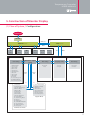
1
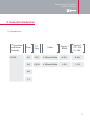
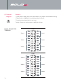
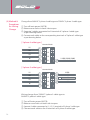
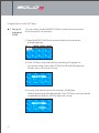
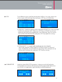
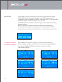
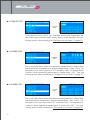
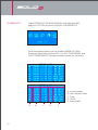
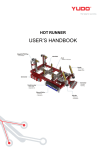
User Manual
User Manual
HEAD OFFICE & FACTORY
169-4 Gujang-Ri, Paltan-Myun, Hwasung-City, Gyeonggi-Do, 445-915 KOREA
Tel: +82 31 350 2530 (Overseas Sales Team) | Fax: +82 31 354 7446 | E-Mail: [email protected] | Website: www.yudo.com
Ver. 1.0 MN BOLD 3 [ 13. Dec ]
We reserve the right to change specifications without notice.
English
Thank you very much
for your purchasing BOLD3(Hot-runner Controller)
Please read this manual carefully before installing and
using this controller. Please contact YUDO about any questions.
02
Temperature Controller
USER MANUAL
1. Confirm supplied units and parts
(1) Supplied units and parts
(2) Safety Precautions
2. General Introduction
(1) Composition
(2) Appearance
3. Installation
.............................................................. 07
............................. 07
............................. 08
..............................................................
.............................
.............................
.............................
.............................
(1) Specifications and right rating
(2) Terminals diagram
(3) Names and functions of each part
(4) Wiring diagram
- 12 ZONE 380VAC 3 phase 4 cable type
- 12 ZONE 220VAC 3 phase 3 cable type
(5) Method of wiring change
4. Operation
...................................... 04
............................. 04
............................. 05
09
09
10
11
12
............................. 14
.............................................................. 15
............................. 15
............................. 16
(1) Operating procedures and method
(2) Controller
5. Construction of Monitor Display
(1) Flow of System
① Start
② Set-up with HOT key
(2) How to change set-up value
1) Model & Monitor Display
2) Applications with HOT Keys
3) Monitor Display for MENU selection
4) User Setting Menu
5) Admin Set
6) Supplier Set
7) Time Set
8) Language Set
9) Error List
(3) Table for Parameters
.......................................
.............................
.............................
.............................
17
17
18
19
.............................
.............................
.............................
.............................
.............................
.............................
.............................
.............................
.............................
.............................
27
28
30
32
33
38
44
47
47
48
............................. 49
03
1. Confirm supplied units and parts
(1) Supplied units and parts
Before operating, please read this manual carefully to avoid problems from misuse.
And this manual should be read by field operator for their full understanding on
operation procedures, and to be kept at proper place whenever accessible.
. The manual is subject to change without notice for product improvement.
. If you have any questions about product and/or find mistakes in this manual,
please contact Head Office or Distributor, from whom you bought.
. We have copy-right of this manual. And it is not allowed by law to copy whole or
a part of this manual without our written permission.
04
1) Confirm supplied
units and parts
When it is delivered, please confirm the supplied units and
parts if they have right specifications as you ordered first.
Further, please confirm its appearance to confirm whether
it is damaged or not.
2) Confirm enclosed
units and parts
. Operation Manual
. BOLD3 Unit
. Mold Relay Cable(Option)
Temperature Controller
USER MANUAL
(2) Safety Precautions
1) Precautions about this Operating Manual
. The Manual should be delivered to field operator for their understanding on Operation
Method and to be kept at proper place whenever accessible.
. Please operate the unit with full understanding and knowledge of the Manual.
. This Operation Manual describes detailed functions of the unit, and we do not warranty
the other functions not described herein.
. This Manual is made with utmost care for safety. However, if found omissions or mistakes etc,
we appreciate your opinion to Sales Dept. of Head Office or Distributor from whom you bought.
. The Manual is subject to change without notice for product improvement or change in functions.
2) Safety Precautions in operation
. In order to protect the system connected to the unit and for safety purpose,
it is requested to strictly follow the instructions described in the Manual.
. We have no responsibility for consequential damages or losses coming from misuse
or carelessness or mishandling of the unit.
. When it is necessary to install separate protection or safety circuitry, it should be installed
outside to protect the system connected to the unit and for safety purpose.
It is not allowed to install the circuitry inside of the unit. Further it is not allowed to change
or add something inside.
. Please do not breakdown or repair or change the unit in any way, which may result
in electric shock, fire or malfunction.
. Do not give shock on the unit, which may result in serious damage or malfunction.
3) Regarding indemnity
. We do not warranty and have no responsibility for the cases which are not mentioned in the Manual.
. We have no responsibility for consequential damage or loss directly or indirectly to user or
to 3rd person from unforeseeable defects or force majeure.
4) Regarding quality guarantee
. We guarantee its quality for one year period from your purchase, during the time we repair
the unit at free of charge in case the trouble comes from normal operation as per instructions
in the Manual.
. After expiry of said guarantee period, we charge repair cost according to our tariff for repair.
. In case of the trouble coming from following cases, we charge repair cost according to
our tariff for repair even in guarantee period.
05
- Troubles by operator’s mishandling
- Troubles by force majeure
- Troubles by moving to the other place after installation
- Troubles by change of the unit at customer’s discretion or damage to the unit.
- Troubles coming from unstable power supply
. If repair is necessary for troubleshooting, please contact Head Office or
Distributor from whom you bought.
5) Cautions for installation
. Electric wiring should be made without electric power.
. Do not work with wet hands to prevent from electric shock.
. Please refer to installation method for grounding. And do not connect grounding cable
to gas pipe, telephone line, or lightning rod.
. Do not supply power until all connections are made between units. Otherwise,
it results in trouble.
. Always right rating electricity should be supplied to the unit. Otherwise, it results in
electric shock and fire.
. Do not install the unit tilted.
. Avoid installing the unit at following places and environment.
- Places where person is apt to contact terminals without knowing what he is doing.
- Place where mechanical vibration or shock may influence the unit.
- Place where corrosive gas or flammable gas exists.
- Place where temperature fluctuation is high.
- Place where is very hot(over 50℃) or very low( below 0℃)
(Particularly, it needs warm-up for more than 30 minutes when operating the unit
at low temperature below 10℃.)
- Place with direct sunlight
- Place where is influenced by electronic wave
- Very humid place over 85% humidity
- Place where many flammable materials exist
- Place with dusty or salty materials
- Place where heat generating equipment exists
- Place where noise producing equipment exists
06
Temperature Controller
USER MANUAL
2. General Introduction
(1) Composition
3rd Generation
Hot Runner
Controller
BOLD3
Zone
T/C
Type
Cables
Option 1
RS485
Option 2
DO : 2EA
DI : 3EA
04
J(IC)
3: 3Phase 3Cable
0: NO
0: NO
06
K(CA)
4: 3Phase 4Cable
1: OK
1: OK
08
12
07
(2) Appearance
1) Dimensions
230
418
Unit : mm
486
2) Weight
4 ZONE : 21 kg / 6 ZONE : 22 kg
8 ZONE : 23 kg / 12 ZONE : 25 kg
08
Temperature Controller
USER MANUAL
3. Installation
(1) Specifications and right rating
Power Supply
Operating
environment
Input
Output
Communication
(if option is available)
Contact point
output
(if option is available)
System
220VAC(±10%) 3 phase 3 cable, 50-60Hz
380VAC(±10%) 3 phase 4 cable, 50-60Hz
Controller Unit
220VAC, 50-60Hz
Temperature
0~50℃
Humidity
20~90%RH (Non-condensing)
Input zones
4,6,8,12 ZONE
Input cycle
100ms
Input type
K(CA), J(IC)
Input coverage
0~400℃
Input accuracy
±0.3% of FS
Output type
Triac (Zero-crossing, phase control)
Output capacity
250VAC/15A
Rating
RS485
Type
2 cable type
Protocol
Modbus RTU
Speed
19200bps
Set-up
None parity, 8 Data, 1 Stop bit
Max. distance
1200m
Connections
31 units
Number of point
2 points
Output type
Relay Normal Open
Output capacity
250VAC 2A, 30VDC 5A
Number of point
2 points
(if option is available)
Input Type
ON/OFF contact point input
Injection signal input
Number of point
1 point
Input type
24VDC or 220VAC signal input
Contact point input
(Option)
09
(2) Terminal
diagram
Cautions
. Cut all power supply to the unit and check if any cable is active before wiring.
. If electricity is supplied, it may bring electric shock.
Do not contact terminals in any case.
. Again, please cut main power supply for wiring.
MOLD CONNECTOR
TERMINAL
CON1
Zone4
Zone5
Zone6
HT4-1
HT1-1
HT4-2
HT1-2
TC4 +
TC1 +
TC4 -
TC1 -
HT5-1
HT2-1
HT5-2
HT2-2
TC5 +
TC2 +
TC5 -
TC2 -
HT6-1
HT3-1
HT6-2
HT3-2
TC6 +
TC3 +
TC6 -
TC3 -
Zone1
Zone2
Zone3
CON2
Zone10
Zone11
Zone12
10
HT10-1
HT7-1
HT10-2
HT7-2
TC10 +
TC7 +
TC10 -
TC7 -
HT11-1
HT8-1
HT11-2
HT8-2
TC11 +
TC8 +
TC11 -
TC8 -
HT12-1
HT9-1
HT12-2
HT9-2
TC12 +
TC9 +
TC12 -
TC9 -
Zone7
Zone8
Zone9
Temperature Controller
USER MANUAL
(3) Names and functions of each part
A
C
B
D
A : ZONE STATUS LED
B : HOT KEY & MENU KEY
C : LCD DISPLAY
D : DIRECTION KEY & SET KEY
E
F
G
H
E : MCB (Miniature Circuit Break)
F : POWER Cable
G : 24P Cable CONN. 1
H : 24P Cable CONN. 2
11
(4) Wiring diagram
- 12 ZONE 380VAC 3 phase 4 cable type
Unit6
Unit5
Unit4
Power
Unit3
Unit2
Unit1
1
2
3
TC11+
FAN
L2
TC12+
TC11TC12-
L1 (N)
L3
HT12-1 HT11-1
L1 (Black)
L2 (Black)
MCCB
L3 (Black)
N (Blue)
L1
PE
L2
L3
N
12
1
1
1
2
2
2
3 TC9+
4
3 TC7+
4
3
5
TC10+
TC9TC10-
5
TC8+
TC7-
4
5
TC8-
TC5+
6
4
7
5
TC6+
TC5TC6-
8
1
1
2
2
3 TC3+
4
3 TC1+
4
5
TC4+
TC3TC4-
5
1
2
TC1-
3
4
TC2+
TC2-
5
6
6
6
6
6
6
7
7
7
7
7
7
8
8
8
8
8
HT11-2
HT12-2
L2 (N)
L1
HT10-1 HT9-1
HT9-2
HT10-2
L3 (N)
L2
HT8-1 HT7-1
HT7-2
HT8-2
L1 (N)
L2
L1 (N)
L3
HT6-1 HT5-1
HT6-2
HT5-2
L2 (N)
8
L1
HT4-1 HT3-1
HT3-2
HT4-2
L3 (N)
L2
HT2-1 HT1-1
HT1-2
HT2-2
L1 (N)
Temperature Controller
USER MANUAL
- 12 ZONE 220VAC 3 phase 3 cable type
Unit6
Unit5
Unit4
Power
Unit3
Unit2
Unit1
1
2
3
TC11+
TC11-
1
1
1
2
2
2
3
3 TC7+
4
3
TC9+
TC9-
4
TC12+
TC12-
5
FAN
L2
L1 (N)
L3
HT12-1 HT11-1
TC10+
TC10-
5
TC8+
TC7-
4
5
TC8-
TC5+
6
4
7
5
TC6+
TC5TC6-
8
1
1
2
2
3 TC3+
4
3
5
TC4+
TC3-
1
2
TC1+
TC1-
4
TC4-
5
3
4
TC2+
TC2-
5
6
6
6
6
6
6
7
7
7
7
7
7
8
8
8
8
8
HT11-2
HT12-2
L2 (N)
L1
HT10-1 HT9-1
HT9-2
HT10-2
L3 (N)
L2
HT8-1 HT7-1
HT7-2
HT8-2
L1 (N)
L2
L1 (N)
L3
HT6-1 HT5-1
HT6-2
HT5-2
L2 (N)
8
L1
HT4-1 HT3-1
HT3-2
HT4-2
L3 (N)
L2
HT1-2
HT2-2
L1 (N)
HT2-1 HT1-1
L1 (Black)
L2 (Black)
MCCB
L3 (Black)
N (Blue)
L1
PE
L2
L3
N
13
(5) Method &
Procedures
for Wiring
Change
Change from 380VAC 3 phase 4 cable type to 220VAC 3 phase 3 cable type
① Turn off main power (MCCB).
② Release cover bolts on back side to open
③ Separate 3 cables connected to N terminal of 3 phase 4 cable type
as per drawing below.
④ Connect each cable to the corresponding terminals of 3 phase 3 cable type
as per drawing below.
[ 3 phase 4 cable type ]
Terminal block
L1
L2
L3
N
L1
L2
L3
L1(N), L2(N), L3(N)
N
[ 3 phase 3 cable type ]
Terminal block
L1
L2
L3
N
L1
L2
L3
L1(N)
L2(N)
L3(N)
N
Wiring change from 220VAC 3 phase 3 cable type to
380VAC 3 phase 4 cable type
① Turn off main power (MCCB).
② Release cover bolts on back side to open.
③ Separate 3 cables connected to L1, L2, L3 terminals of 3 phase 3 cable type.
④ Connect each cable to the N terminals of 3 phase 4 cable type.
14
YUDO Temperature Controller
USER MANUAL
4. Operation
(1) Operating
Procedures
and Method
1) Check connector wirings and sensors if they are arrayed as per specifications.
2) Check connector sensors and heater wirings are separated each other.
Further check if wirings are properly made to corresponding sensors.
3) Check specifications of relays [size of connectors, number of pins].
4) Check heater resistance, insulation, and if sensors are opened or not.
5) Install mold to injection machine and connect it to relay wire.
6) Check main power switch is OFF. If not, make it OFF.
7) Check input power (220 / 380 VAC) is same as set-up power rating.
If found correct, connect input power. Input power rating is indicated
in the label on back side. If input power is different from specified power
rating, please contact distributor for proper solution.
Different input power from specifications results in damage to the unit
or malfunction.
8) Grounding cable should be connected to ground. Without grounding,
noise may influence the unit to make damage to fuse and TRIAC,
finally result in power leakage and electric shock.
9) Check overall wiring arrangements.
10) Make main power switch ON. Under normal condition,
fans on both sides are working.
※ To go to next step, check if FANS are working.
11) Under normal condition, front LCD display is lit for operation.
12) Check if the operation is working normal.
※ Input power set-up once in the beginning is enough for further ongoing operations. .
15
(2) Controller
Composition of
Front Panel
LCD
. Shows PV(present temp.), SV(Set-up temp), MV(Output volume),
Sensor type, Present conditions.
. Shows errors in the operation.
. Shows parameters and changes made.
ZONE STATUS
. Indicates conditions of ZONE. Red LED indicates trouble while
Blue LED indicates normal operation.
Left HOT key &
Menu key
. TEMP.SV : HOT key entering into MENU for SV change.
. RUN/STOP : HOT key entering into MENU to input OPERATION/STOP.
. MODE : HOT key entering into MENU to input STANDBY/ BOOST mode.
. MENU/ESC : HOT key entering into MENU OR RETURN.
Right direction key
. ▼/▲/◀/▶: Direction Key for moving control sector or value change
. SET: Key for saving the value or value change
Main Display for
different ZONES
4 ZONE
6 ZONE
8 ZONE
12 ZONE
16
Temperature Controller
USER MANUAL
5. Construction of Monitor Display
(1) Flow of System / Configuration
POWER ON
1)
MODEL
3)
MENU 3Sec
MENU Screen
MONITOR Screen
SV
MENU
RUN
MENU
MENU
MODE
MENU
2)
SV
Setting
RUN
Mode
STOP
Mode
Auto
Mode
4)
Standby
Mode
7)
User Setting
1. ZONE ON/OFF
2. Sensor Type
3. Alarm High
4. Alarm Low
5. Standby SV
6. Standby Time
7. Boost SV
8. Boost Time
9. Boost MV
10. SV Lock
11. User Setting Lock
12. VERSION Display
13. Commuication ID
Administrator / Supplier
Setting
9)
Language Setting
1. Korean
2. English
Error History
1. Error Time
/ Contents
Supplier
P/W
5)
1. Temp Unit
2. Temp Preset
3. Control Output Type
4. Manual Mode
5. Manual MV
6. P Parameter
7. I Parameter
8. D Parameter
9. Control Hysteresis
10. Control Gain
11. Auto Tuning Mode
12. PV Sync
13. Heater Sync
14. AUTO ZONE ON/OFF
15. User Password
16. Admin Password
17. Factory Init
MENU
8)
Time Setting
2013.06.18
14:00
Admin
P/W
SET
Boost
Mode
6)
MENU
1. Sensor Reversed Set
2. RJC Manual Mode
3. RJC Preset
4. Soft start Set
5. Soft start End Rate
6. Auto Tuning Set
7. PV Low pass filter
8. Error History Clear
Supplier Mode
Administrator Mode
17
① Start
4 ZONE
POWER ON
6 ZONE
8 ZONE
12 ZONE
18
Temperature Controller
USER MANUAL
② Set-up with HOT key
A. Set-up individual Zone
MENU
/ ESC
SET
▶
MENU
/ ESC
MENU
/ ESC
B. Set-up SV
SV
MENU
/ ESC
C. RUN/STOP
RUN/
STOP
MENU
/ ESC
D. Mode selection
MODE
MENU
/ ESC
E. Entering Into Zone
Display Or Return
MENU
3Sec
MENU
/ ESC
19
F. USER SET
SET
SET
MENU
/ ESC
MENU
/ ESC
SET
MENU
/ ESC
SET
MENU
/ ESC
SET
MENU
/ ESC
SET
MENU
/ ESC
SET
MENU
/ ESC
20
Temperature Controller
USER MANUAL
SET
MENU
/ ESC
SET
MENU
/ ESC
SET
MENU
/ ESC
SET
MENU
/ ESC
SET
MENU
/ ESC
SET
MENU
/ ESC
SET
MENU
/ ESC
21
G. ADMIN SET
SET
MENU
/ ESC
SET
MENU
/ ESC
SET
MENU
/ ESC
SET
MENU
/ ESC
SET
MENU
/ ESC
SET
MENU
/ ESC
SET
MENU
/ ESC
SET
MENU
/ ESC
22
Temperature Controller
USER MANUAL
SET
MENU
/ ESC
SET
MENU
/ ESC
SET
MENU
/ ESC
SET
MENU
/ ESC
SET
MENU
/ ESC
SET
MENU
/ ESC
23
SET
MENU
/ ESC
SET
MENU
/ ESC
SET
MENU
/ ESC
SET
MENU
/ ESC
SET
MENU
/ ESC
24
Temperature Controller
USER MANUAL
H. SUPPLIER SET
SET
MENU
/ ESC
SET
MENU
/ ESC
SET
MENU
/ ESC
SET
MENU
/ ESC
SET
MENU
/ ESC
SET
MENU
/ ESC
SET
MENU
/ ESC
SET
MENU
/ ESC
25
SET
MENU
/ ESC
SET
MENU
/ ESC
I. TIME SET
SET
MENU
/ ESC
J. LANGUAGE SET
SET
MENU
/ ESC
K. ERROR LIST
SET
MENU
/ ESC
26
Temperature Controller
USER MANUAL
(2) How to change set-up value
▶ Four different methods are available for change of set-up value.
Change of set-up value ① : You can find a cursor with which you can change set-up
value of zone selected, and hit SET KEY for saving the value.
Change of set-up value ② : You can find a cursor as per drawing below with which
you can change set-up value of the zone selected. Then hit SET KEY for saving the value.
Change of set-up value ③ : You can move white circle with cursor to change set-up value.
Change of set-up value ④ : Following drawing would be displayed for change of password.
Above four methods for set-up value change are applicable in same
manner to set-up of user and controller, supplier. In this connection,
above numbers would be quoted without explanations henceforth.
27
1) Model & Monitor Display
- When power switch ON, followings shall be displayed on monitor showing
Model Number and present conditions.
- There are 4 different drawings showing 4 ZONE, 6 ZONE, 8 ZONE, 12 ZONE on monitor.
Model display /
Monitor display /
4 ZONE
6 ZONE
8 ZONE
12 ZONE
28
Temperature Controller
USER MANUAL
Monitor display configuration
(A)
(B)
(C)
(D)
(E)
(F)
(G)
(H)
(A)PV : Present Temperature
(B)SV : Set-up Temperature
(C)MV : Output volume (0~100%)
(D)Error indicator
- AC.Er : Power frequency error
- AD.Er : ADC error
- AL-H : Alarm Max. error
- AL-L : Alarm Min. error
- Ca.Er : Calibration error
- CT.Er : CT error
- FUSE : FUSE open error
- GR.St : Current monitor error
- HT.OP : Heater open error
- HT.St : Heater short error
- MV_Er : Min. Temp. error
- OV_Er : Max. Temp. error
- RJ.Er : RJC error
- TC.OP : Sensor open
- TC.Re : Sensor wiring mistake
- TC.St : Sensor short error
- Tr_St : TRIAC short error
- Tr_TH : TRIAC overheat
(E)Temp. Unit(℃/℉)
(F)Current Status
- STP : Stop
- RUN : Running
- STBY : Standby
- BST : Boost
(G)Zone Activity Indicator(Enable/Disable)
(H)Sensor Type(K/J)
29
2) Applications with HOT Keys
▶1. Set-up of
individual
ZONE
You can select simply WANTED ZONE to make it Active/Inactive
or to change SV set-up value.
i) Select WANTED ZONE from monitor display with up/down
and left/right Key.
ii) Once SET Key is pressed, following drawing will appear for
set-up new value. Then select ZONE On/Off with left/right Key.
Further, press SET Key for saving.
iii) In case, you want to set-up SV and press DOWN key,
following drawing will be displayed. Press SET Key to set-up wanted
temperature and press SET Key again for saving.
30
Temperature Controller
USER MANUAL
▶2. SV
Two different types shall be displayed as follows. You can select one
of two types with left/right Key and press SET Key or DOWN Key.
i) ZONE ALL : Useful to change all or individual ZONE. First select wanted
ZONE with direction KEY. And press SET Key or DOWN Key to have
following drawing to be appeared. In this drawing, you can set-up
new value with direction Key and press SET Key again for saving.
ii) ZONE SELECT : It is applicable to change set-up value for
the ZONE selected. Select WANTED ZONE(S) with SET Key and
press DOWN Key to have following drawing. Then change set-up
value with Direction Key and press SET Key for saving.
▶3. RUN/STOP
Useful to select RUN/STOP operation. Select one with left/right Key.
If all ZONES are inactive, left drawing shall be appeared while even
one ZONE is in operation, right drawing shall be appeared.
31
▶4. MODE
. Applicable to choose the other MODE under operating condition.
Select MODE with left/right Key, then press SET Key for saving.
. Three MODES are available (NORMAL, STANDBY, BOOST) for selection.
. NORMAL MODE is operating by normal control.
. STANDBY MODE is used for maintaining preset temperature during
the preset time.
. BOOST MODE is used for increasing output at preset volume
for the preset time at preset temperature. It stops BOOST MODE
when either one of preset temperature or time reaches preset value.
3) Monitor Display -Press MENU/ESC Key for 3 seconds to have following display.
for MENU selection -Select a MENU and press SET Key for entering sub category MENU.
-For setting USER and ADMIN, you have to select one from
sub category MENU.
32
Temperature Controller
USER MANUAL
4) USER SETTING
MENU
- On the MENU display, you can select USER SETTING MENU with
left/right KEY and hit SET KEY to enter into lower category MENU.
- Followings would be displayed in Lower MENU, and you would
select one and hit SET KEY to enter into selected menu.
▶1. ZONE
ON/OFF
SET
You can decide to make ZONE RESPECTIVELY active or inactive. As you
understand, it is possible to operate under active condition of course.
Further, under active condition it is possible to monitor error to
indicate ERROR MESSAGE with buzzer sound. On the contrary, under
inactive condition it NOT possible to operate and to monitor error.
You can change set-up value according to Change of set-up value ②
(page 27).
33
▶2. SENSOR TYPE
SET
Two types of sensor, K(CA), J(IC) are used for the unit. Depending on
the sensor type used for mold, sensor type is to be decided. You can
change preset value according to Change of set-up value ② (page 27).
▶3. ALARM HIGH
SET
This is to make alarm when the operating temperature is higher than
preset Maximum temperature (preset temperature + Max. Limit). For
example, if max. limit is preset at 10℃ based on 100℃ SV temperature,
it alarms when operating temperature is higher than 110℃. You can
change preset value according to Change of set-up value ①(page 27).
▶4. ALARM LOW
SET
This is to make alarm when the operating temperature is lower than
preset Minimum temperature (preset temperature – Min. Limit). For
example, if min. limit is preset at 10℃ based on 100℃ SV temperature,
it alarms when operating temperature is lower than 90℃. You can
change preset value according to Change of set-up value ①(page 27).
34
Temperature Controller
USER MANUAL
℃
210℃
200℃
195℃
Alarm
high
Alarm
low
Above drawing shows two alarming cases when you set-up
alarming Max. Limit with 10℃, alarming Min. Limit with 5℃.
Alarm sounds during operation of equipment.
▶5. STANDBY
SV
SET
This is to maintain preset temperature in STANDBY MODE for the
preset time by selecting STANDBY MODE under operating condition.
When STANDBY TIME passed, it returns to RUN MODE. You can change
preset value according to Change of set-up value ①(page 27).
▶6. STANDBY
TIME
SET
This is to maintain preset temperature in STANDBY MODE during preset
STANDBY TIME by selecting STANDBY MODE under operating condition.
When STANDBY TIME passed, it returns to RUN MODE. You can change
preset value according to Change of set-up value ①(page 27).
35
℃
200 ℃
150 ℃
Time
60 Min
Above drawing shows operation with 150℃ STANDBY Temperature and
60 min. STANDBY Time.
▶7. BOOST SV
SET
This is useful to set-up BOOST SV during BOOST TIME. When in
operation, select BOOST MODE and BOOST SV. You can change preset
value according to Change of set-up value ①(page 27).
▶8. BOOST TIME
SET
This is useful to set-up BOOST TIME in BOOST MODE. When in operation,
select BOOST MODE and BOOST TIME. You can change preset value
according to Change of set-up value ①(page 27).
36
Temperature Controller
USER MANUAL
▶ 9. BOOST MV
SET
This is useful to set-up required BOOST MV in BOOST Mode during
BOOST Time. When in operation, select BOOST Mode and BOOST MV.
You can change preset value according to Change of set-up value ①
(page 27).
℃
250℃
ZONE 1
ZONE 2
200℃
Time
10 Sec
Above drawing shows operation with 250℃ BOOST SV and
10 sec. BOOST Time, 100% BOOST MV.
▶10. SV LOCK
SET
This is useful to protect certain zone from unwanted change of SV
VALUE. It is possible to set-up each zone with ON(to make the zone
active) and OFF(to make the zone inactive). You can change preset
value according to Change of set-up value ②(page 27).
▶11. USER SETTING
LOCK
SET
This is useful to decide whether it is necessary to input PASSWORD in
USER SET-UP. You can select either one of ON or OFF. You can change
preset value according to Change of set-up value ③( page 27).
37
▶12. VERSION
DISPLAY
SET
It is useful to confirm VERSION of the unit and DISPLAY, which is
unchangeable.
▶13. COMMUNICATION
ID
SET
If COMMUNICATION OPTION is available, it is useful to set-up
COMMUNICATION ID from 01 to 99.
5) ADMIN SET
- If you find following drawing in MENU, select ADMIN SET with
left/right Key. Then it requires to input PASSWORD of CONTROLLER.
After input of PASSWORD, sub-category MENU will be appeared. If you
input SUPPLIER PASSWORD, it will go into SUB CATEGORY MENU for
SUPPLIER.
- Followings are Sub-category MENU. You can select with up/down Key.
Press SET Key for saving, which enables to entering into changed drawing.
38
Temperature Controller
USER MANUAL
▶1. TEMP UNIT
SET
You can select temperature unit in C. degree or F. degree, and with
prime number or with decimal point as well. You can change preset
value according to Change of set-up value ③( page 27).
▶2. TEMP PRESET
SET
It is useful to compensate certain value if there is a difference between
actual temperature and SV temperature. You can change preset value
according to Change of set-up value ①(page 27).
▶3. CONTROL
OUTPUT TYPE
SET
This is useful to decide Output MODE. At the moment, Phase Angle
Control(Auto) and ZERO CROSSING(Zero Cross Control(Fix Pulse)) are
available.
39
ZCC FP
Output
PAC AT
You can change preset value according to Change of
set-up value ②(page 27).
▶4. MANUAL MODE
SET
It is used for set-up MANUAL MODE with ON. If designated ZONE is
under NORMAL OPERATION, it outputs with preset volume. You can
change preset value according to Change of set-up value ②(page 27).
▶5. MANUAL MV
SET
It is used for set-up MANUAL MV. MANUAL MV will be produced in the
Zones with preset ON on MANUAL MODE. You can change preset
value according to Change of set-up value ①(page 27).
▶6. P PARAMETER
SET
It is useful to set-up Propotional Control Parameter in PID Control. We
do not recommend changing preset value because it may influence
Temperature Control. You can change preset value according to
Change of set-up value ①(page 27).
40
Temperature Controller
USER MANUAL
▶7. I PARAMETER
SET
It is useful to set-up Integration Control Parameter in PID control. We
do not recommend changing preset value because it may influence
Temperature Control. You can change preset value according to
Change of set-up value ①(page 27).
▶8. D PARAMETER
SET
It is useful to set-up Differential Coefficient Parameter in PID control.
We do not recommend changing preset value because it may
influence Temperature Control. You can change preset value according
to Change of set-up value ①(page 27).
▶9. CONTROL
HYSTERESIS
SET
It is useful parameter to control ON/OFF. We do not recommend
changing preset value because it may influence Temperature Control.
You can change preset value according to Change of set-up value ①
(page 27).
▶10. CONTROL
GAIN
SET
It is useful to set-up CONTROL GAIN. We do not recommend changing
preset value because it may influence TEMPERATURE CONTROL. You can
change preset value according to Change of set-up value ①(page 27).
41
▶11. AUTO TUNING
MODE
SET
Two AUTO TUNING MODES are available, FULL and QUICK MODE.
AUTO TUNING is processing with raising Temperature in QUICK MODE,
while preset TUNING MODE is working in FULL TUNING MODE. You can
change preset value according to Change of set-up value ②(page 27).
▶12. PV SYNC
SET
When we raise temperature, in case nozzle gets heat faster than
manifold, there would be gas emission or carbonization. In order not
to have such problem, it is useful to make them get heat at the same
phase.
℃
90 %
Manifolder
SV
Nozzle
t
PV SYNC
Manifolder
90%
℃
Manifolder
90%
℃
SV
SV
t
t
STATUS
SST
PVC
AT
PV SYNC mode Nozzle
RUN
STATUS
SST
AT
RUN
PV SYNC mode Manifolder
As per two drawings above, at the time of Completion Of Nozzle’s Soft
Start, it controls nozzle and manifold separately. Nozzle will maintain
the temperature of Soft Start until manifold gets heat 90% of SV
Temperature. And when manifold gets over 90% heat of SV, Nozzle
Gets Heat to reach SV at about same time as MANIFOLD. You can
change preset value according to Change of set-up value ③(page 27).
42
Temperature Controller
USER MANUAL
▶13. HEATER SYNC
SET
It is useful to control the ZONE where sensor has opened with same
heater as the ZONE equipped with. For this function, you can set-up
the ZONE number to have damaged ZONE same output. You can
change preset value according to Change of set-up value ①(page 27).
▶14. AUTO ZONE
ON/OFF
SET
It is useful to set-up each ZONE unit to make it automatically ON or
OFF, when we make Switch-On. In case of OFF, you may activate ZONE
at ZONE ON/OFF MENU as per preset value. You can change preset
value according to Change of set-up value ③( page 27).
▶15. USER
PASSWORD
SET
It is used for set-up User Password. You can change User Password
when you input preset User Password. You can change preset value
according to Change of set-up value ④( page 27).
43
▶16. ADMIN
PASSWORD
SET
It is used for set-up Administrator Password. You can change Administrator
Password when you input preset Administrator Password. You can
change preset value according to Change of set-up value ④( page 27).
▶17. FACTORY INIT
SET
It is used to reset to factory specifications. In case you select ON, the
system is working for reset to factory preset specifications with taking
some time. When RESET is completed, it shows OFF automatically.
Until that time, operator should wait without working with the unit.
You can change preset value according to Change of set-up value ③
(page 27).
6) SUPPLIER SET
-First select CONTROLLER SET-UP, and then press SET Key to have
ADMIN PASSWORD on monitor. At this time, if you input SUPPLIER
PASSWORD, it goes to sub-category for SUPPLIER MENU.
-Sub-category is as follows to select with up/down Key.
Then press SET Key to enter into sub MENU
44
Temperature Controller
USER MANUAL
▶1. SENSOR
REVERSED SET
SET
When you found problem in MOLD SENSOR POLARITY or in wiring
between MOLD and CONTROLLER TERMINAL, CONTROLLER comes to
know there is a problem in SENSOR POLARITY. If you set-up ON, the
unit senses that SENSOR POLARITY has been changed. You can
change preset value according to Change of set-up value ②( page 27).
▶2. RJC SENSOR
MANUAL MODE
SET
If you found a problem with RJC SENSOR, you can SET-UP RJC SENSOR
VALUE IN MANUAL. However, there may be some difference in PV
TEMPERATURE. You can change preset value according to Change of
set-up value ②(page 27).
▶3. RJC SENSOR
PRESET
SET
If you find DIFFERENCE between TERMINAL TEMPERATURE and RJC
SENSOR TEMPERATURE, you can assign certain value to have them
same TEMPERATURE. You can change preset value according to
Change of set-up value ①(page 27).
▶4. SOFT START SET
SET
It is useful to set-up SOFT START when we start operating the unit. If
you set-up ON, it implements SOFT START. You can change preset
value according to Change of set-up value ② (PAGE 27).
45
▶5. SOFT START
END RATE
SET
It is useful to set-up SOFT START COMPLETION TEMPERATURE PERCENTAGE
in comparison with SV TEMPERATURE. For example, SV temperature is 300℃
while SOFT START is 50%, SOFT START will be going up to 150℃. You can
change preset value according to Change of set-up value ①(page 27).
▶6. AUTO TUNING
SET
SET
It is useful to have the unit AUTO TUNING automatically. In this case,
for each ZONE with ON, it will have AUTO TUNING process whenever it
starts operation.You can change preset value according to Change of
set-up value ②(page 27).
▶7. PV LOW
PASS FILTER
SET
It is useful to set-up to show AVERAGE TEMPERATRE for certain time to
represent PRESENT TEMPERATURE. You can change preset value
according to Change of set-up value ①(page 27).
▶8. ERROR HISTORY
CLEAR
SET
It is useful to delete all ERROR HISTORY. If you click ON, all ERROR
HISTORY shall be deleted. You can change preset value according to
Change of set-up value ③(page 27).
46
Temperature Controller
USER MANUAL
7) TIME SET
- Select TIME on MENU display with left/right Key. Once SET Key is
pressed, it will go to sub category MENU to set-up present time.
- On this display, you can change the time with up/down,
left/right Key and press SET KEY for saving. SET KEY must be
pressed for saving.
8) LANGUAGE SET
- Select LANGUAGE from MENU DISPLAY with left/right Key and
press SET KEY to go into LANGUAGE SETTING MENU.
- Select wanted LANGUAGE on the screen below with up/down Key and
press SET KEY for saving. At the moment, two languages, KOREAN and
ENGLISH are available. You can change preset value according to
Change of set-up value ③(page 27).
47
9) ERROR LIST
- Select ERROR LIST ON MENU DISPLAY with left/right KEY,
and press SET KEY to go into DISPLAY FOR ERROR LIST.
- From the display below, we can confirm ERROR LIST filed
to present time with up/down KEY. It is NOT CHANGEABLE and
JUST FOR REFERENCE. It accommodates maximum 180 errors.
A : Serial number
B : Year/ Month/ Date
C : Time
D : ZONE
E : Error details
A
48
B
C
D
E
Temperature Controller
USER MANUAL
(3) TABLE FOR PARAMETERS
▶OPERATION DISPLAY
Setting
Meaning
Category
Useability
Factory
Preset
MODE
Mode Selection
NORMAL
whenever
NORMAL
STANDBY
BOOST
SV
Temperature Target
0~400℃
whenever
0℃
RUN/STOP
Run/stop Selection
RUN, STOP
whenever
STOP
Setting
Meaning
Category
Useability
Factory
Preset
ZONE ON/OFF
Selection Of Zone Activity
ON/OFF
whenever
ON
SENSOR TYPE
Selection Of Sensor Type
K(CA) / J(IC) whenever
K(CA)
ALARM HIGH
Set Up Alarming Max Limit
0~400℃
whenever
0℃
ALARM LOW
Set Up Alarming Min Limit
0~400℃
whenever
0℃
STANDBY SV
Set Up Temp. In Standby Mode
0~400℃
whenever
150℃
STANDBY TIME
Set Up Time In Standby Mode
0~999 Min whenever
60 Min
BOOST SV
Temp In Boost Mode
0~400℃
whenever
0℃
BOOST TIME
Running Time In Boost Mode
0~999 Sec
whenever
0 Sec
BOOST MV
Output In Boost Mode
0~100 %
whenever
0%
SV LOCK
Locking Zone Sv Value.
ON/OFF
whenever
OFF
USER SETTING LOCK
Locking User
ON/OFF
whenever
OFF
VERSION DISPLAY
Model And System Version No.
-
whenever
-
01~99
whenever
01
▶ SET-UP USER
COMMUNICATION ID Set Up Communication Id
49
▶SET-UP ADMIN
Setting
Meaning
Category
Useability
Factory
Preset
TEMP UNIT
Dicimal Point, F. Degree,
C.Degree Selection
0 / 0.1 , ℃ / ℉
whenever
0,℃
TEMP. PRESET
Set Up Temp. Compensation
-99~999 ℃
whenever
0℃
CONTROL OUTPUT TYPE Selection Output Controlmode
ZCCfp / PACat
whenever
ZCCfp
MANUAL MODE
Selection Of Manual Output
ON/OFF
whenever
OFF
MANUAL MV
Set Up Manual Output Volume
0~100 %
whenever
0%
P PARAMETER
Set Up Proportional Control Ratio
0~400 ℃
whenever
15 ℃
I PARAMETER
Set Up Integral Control Value
0~3600 Sec
whenever
60 Sec
D PARAMETER
Set Up Differential Control Value
0~3600 Sec
whenever
15 Sec
CONTROL HYSTERESIS
Set Up Value For Control
0~10 ℃
whenever
0℃
100 %
CONTROL GAIN
Set Up Proportional Amp. Ratio
0~100 %
whenever
AUTO TUNING MODE
Selection Of Auto Tuning Mode
QUICK / FULL
whenever
QUICK
PV SYNC
Control Same PV Value Between
Channels
ON / OFF
whenever
OFF
HEATER SYNC
Set Up Zones to be Synchronized
0~12 ZONE
whenever
0 ZONE
AUTO ZONE ON/OFF
Set Up Auto Zone ON/OFF
ON / OFF
whenever
ON
USER PASSWORD
Set Up User Password
0000~9999
whenever
0000
ADMIN PASSWORD
Set Up Administer Password
0000~9999
whenever
0000
FACTORY INIT
Reset To Factory Preset Value
ON / OFF
whenever
OFF
50
Temperature Controller
USER MANUAL
▶SET-UP SUPPLIER
Useability
Factory
Preset
Setting
Meaning
Category
SENSOR REVERSED SET
Select when sensor polarity
is reversed
ON / OFF
whenever
OFF
RJC SENSOR MANUAL MODE Set up when RJC sensor has problem ON / OFF
whenever
OFF
RJC SENSOR PRESET
Set up Temp. Compensation
Value of RJC sensor
-50~50 ℃
whenever
0℃
SOFT START SET
Slection to activate SOFT START
ON / OFF
whenever
OFF
SOFT START END RATE
Set up Proportional Temp.
Ratio for completion of SOFT START 0~100 %
in comparison with SV Temp.
whenever
0%
AUTO TUNING SET
Set up Auto Tuning
ON / OFF
whenever
ON
PV LOW PASS FILTER
Set up filtering value of PV
0~100
whenever
0
ERROR HISTORY CLEAR
Selection whether to delete
error report or not
ON / OFF
whenever
OFF
▶TIME SET-UP
Useability
Setting
Meaning
Category
TIME SET
Set up current time
-
Setting
Meaning
Category
Useability
LANGUAGE SET
Selection of language
KOR / ENG
permanent
Setting
Meaning
Category
Useability
ERROR LIST
Check error report
-
-
Factory
Preset
-
▶LANGUAGE SET-UP
Factory
Preset
KOR
▶ERROR LIST
-
Factory
Preset
51
▶TROUBLE SHOOTINGS
Error
Indicator
Meaning
Trouble Shooting
TC.St
Sensor Wire Opened
Check sensor wire of mold to replace the sensor
TC.OP
Sensor Wire Short
Check sensor wire of mold to replace the sensor
TC.Re
Reversed Polarity of
Sensor Wire
Check connecters of mold and controller if its polarity is reversed.
If yes, change wiring to have right polarity.
Tr_St
TRIAC Short
Continue to produce output due short triac short. Replace TRIAC.
Tr_TH
TRIAC Overheat
Check if grease is sufficient between triac and heat sink.
also check if two fans are properly working.
If they are not working, replace it.
FUSE
Fuse Short
Replace fuse of the zone in trouble.
HT.OP
Heater Short
Check heater wiring to replace heater.
HT.St
Heater Open
Check if heater and mold are connected correctly.
Ca.Er
Calibration Error
Not calibrated or wrong calibration was made.
Contact manufacture to calibrate.
CT.Er
CT current Error
Failure in monitoring current. Contact manufacturer to verify problem.
AD.Er
ADC Error
Defect of ad converter. Contact manufacturer to verify problem.
AC.Er
AC Monitoring Error
No signal about ac. Check wirings. If no problem found,
contact manufacturer to verify problem.
RJ.Er
RJC Error
Check if connection to rjc is correctly wired. If no problem found,
contact manufacturer to verify problem.
MV_Er
Lower Temp.
than lowest limit
Check if temp. Sensor works properly
OV_Er
Higher Temp.
than highest limit
Check if temp. Sensor works properly
AL-H
Higher Temp. than
highest Temp. tolerance
Temp. Is higher than preset highest temp limit
(Sv + alarming temp allowance).
AL-L
Lower Temp. than
lowest Temp. tolerance
Temp. Is lower than preset lowest temp limit
(Sv - alarming temp allowance)
52
Temperature Controller
USER MANUAL
MEMO
53
Global Network
FINLAND
NETHERLANDS
GERMANY
RUSSIA
CZECH
POLAND
U.K
FRANCE
SLOVAKIA
ITALY
PORTUGAL
ROMANIA
SPAIN
TURKEY
ISRAEL
EGYPT
SYRIA
KOREA
IRAN
JAPAN
CHINA
TAIWAN
BANGLADESH
INDIA
VIETNAM
THAILAND
MALAYSIA
PHILIPPINES
SINGAPORE
INDONESIA
SOUTH AFRICA
AUSTRALIA
SINGAPORE
ASIA & OCEANIA
54
YUDO WANCO PTE. LTD.
Tel : + 65 6264 1166
e-mail : [email protected]
CHINA
JAPAN
GUANGDONG YUDO HOT RUNNER SYSTEM CO., LTD.
Tel : + 86 769 8539 4466
e-mail : [email protected]
YUDO (HONG KONG) ENTERPRISE CO.,LTD.
Tel : + 852 2344 5180
e-mail : [email protected]
YUDO TIANJIN OFFICE
Tel : + 86 22 5839 9351
e-mail : [email protected]
YUDO (SUZHOU) H.R.S. CO.,LTD.
Tel : + 86 512 6504 8882
e-mail : [email protected]
YUDO (SHANGHAI) OFFICE
Tel : + 86 21 5138 6422
e-mail : [email protected]
YUDO (NINGBO) OFFICE
Tel : + 86 574 8711 3033
e-mail : [email protected]
YUDO (QINGDAO) HOT RUNNER SYSTEM CO.,LTD.
Tel : + 86 532 8765 1698
e-mail : [email protected]
YUDO (QINGDAO) HOT RUNNER SYSTEM CO.,LTD.
(WEIHAI) OFFICE
Tel : + 86 631 567 2582
e-mail : [email protected]
YUDO (QINGDAO) HOT RUNNER SYSTEM CO.,LTD.
(DAILIAN) OFFICE
Tel : + 86 131 3002 3765
e-mail : [email protected]
WEIHAI YUDO MACHINERY CO., LTD.
Tel : +86 631 597 2588
e-mail : [email protected]
KUNSHAN YUDO-SUNS CO.,LTD.
Tel : + 86 512 5791 0286
YUDO JAPAN CO., LTD.
Tel : + 81 3 5714 4801
e-mail : [email protected]
-Nagoya Office
Tel : + 81 52 745 0361
e-mail : [email protected]
-Kyushu Office
Tel : + 81 92 473 4808
e-mail : [email protected]
MAWANCO SDN BHD. KL office
Tel : + 60 3 8945 2127
e-mail : [email protected]
YUDO WANCO (MALAYSIA) SDN BHD. JB office
Tel: +60 7 2881 226
e-mail: [email protected]
TAIWAN
YUDO WANCO(THAILAND) CO., LTD.
Tel : +66 2 174 7236~40
e-mail : [email protected]
YUDO HOT RUNNER CO., LTD. (TAIWAN BRANCH)
Tel : + 886 2 2205 6677
e-mail: [email protected]
INDIA
YUDO HOT RUNNER INDIA PVT. LTD.
Tel : + 91 250 3200922
e-mail : [email protected]
-Delhi Branch Office
Tel : +91 120 454 9076
e-mail : [email protected]
-Pune Branch Office
Tel : +91 7798884634
e-mail : [email protected]
-Chennai Branch Office
Tel : +91 8939625089
e-mail : [email protected]
PHILIPPINES
YUDO WANCO PHILIPPINES INC
Tel : + 63 949 307 1950
e-mail : [email protected]
MALAYSIA
THAILAND
BANGLADESH
YUDO (BD) PVT. LTD.
Tel : + 88 02 9014 632
e-mail: [email protected]
INDONESIA
PT.YUDO INDONESIA
Tel : + 62 21 29083283
e-mail : [email protected]
PT GAYA STEEL
Tel : + 62 21 89832277
e-mail : [email protected]
VIETNAM
HOA VAN HOA COMPANY LTD.
-Hanoi office
Tel : + 84 43 78 77 179
e-mail : [email protected]
-Hochiminh office
Tel : + 84 938 36 23 77
e-mail : [email protected]
AUSTRALIA
STM AUSTRALIA PTY. LTD.
Tel : + 61 3 9805 9510
e-mail : [email protected]
NEW ZEALAND
STM SALES LTD.
Tel : + 64 9 8206454
e-mail : [email protected]
SYRIA
SAWAS TRADING GROUP
Tel : + 963 21 2254756
e-mail : [email protected]
ISRAEL
ASI-AFASPEM ISRAEL LTD.
Tel : + 972 4 6802770
e-mail : [email protected]
IRAN
YUDO IRAN
Tel : + 98 21 22066506~7
e-mail : [email protected]
Temperature Controller
USER MANUAL
USA
MEXICO
Headquarters
Plant
Subsidiary
Sales Office
Agency
COLOMBIA
PERU
BRAZIL
CHILE
NEW ZEALAND
ARGENTINA
PORTUGAL
AMERICA &
EUROPE & AFRICA
YUDO EU SA.
Tel : + 351 244 570 390
e-mail : [email protected]
PERU
TOTALMATRIX S.A.C.
Tel : + 51 1 447 1652
e-mail : [email protected]
FRANCE
GERMANY
YUDO FRANCE
Tel : + 33 2 3277 4200
e-mail : [email protected]
YUDO GERMANY GmbH.
Tel : + 49 711 707 30370
e-mail : [email protected]
SPAIN
NETHERLANDS
YUDO IBERICA S.L.
Tel : + 34 93 715 81 22
e-mail : [email protected]
YUDO BENELUX
Tel : + 31 (0)13 5705252
e-mail : [email protected]
ROMANIA
SLOVAKIA
ROMOULD YUDO ROMANIA
Tel : + 40 213 272 115
e-mail : [email protected]
YUDO SLOVAKIA s.r.o.
Tel : + 421 335 333 363
e-mail : [email protected]
TURKEY
POLAND
YUDO TURKEY
Tel : + 90 212 320 95 63
e-mail : [email protected]
EUROTECH HOLDING Sp. z o.o.
Tel : + 48 22 843 05 79
e-mail : [email protected]
ARGENTINA
Modular Mold Normalizados S.A.
Tel : + 54 11 4756 7272
e-mail : [email protected]
U.K.
ITALY
FINLAND
EGYPT
YUDO (UK) LTD.
Tel : + 44 1989 763423
e-mail : [email protected]
YUDO ITALY SRL
Tel : + 39 2 99 551 78
e-mail: [email protected]
YUDO Nordic Oy
Tel : + 358 3 616 1847
e-mail : [email protected]
C&C CORPORATION
Tel : + 20 2 2516 7926
e-mail : [email protected]
CZECH
RUSSIA
BRAZIL
REPUBLIC OF SOUTH AFRICA
YUDO CZ
Tel : + 420 724 358 612
e-mail : [email protected]
OOO YUDIX
Tel : +7 495 723 5221
e-mail : [email protected]
YUDO SA BRAZIL
Tel : + 55 47 3435 0022
e-mail : [email protected]
HESTICO PTY. LTD.
Tel : + 27 11 786 5228
e-mail : [email protected]
U.S.A.
YUDO INC. (Head Office)
Tel: +1 614 873 1300
e-mail: [email protected]
- Western Territory (Sales Office)
Tel: +1 562 266 6628
e-mail: [email protected]
- Central Territory (Sales Office)
Tel: +1 630 529 7487
e-mail: [email protected]
- Mid-Western Territory (Sales Office)
Tel: +1 937 478 9039
e-mail: [email protected]
- Eastern Territory (Sales Office)
Tel: +1 616 644 5615
e-mail: [email protected]
CHILE
TOTALMATRIX E.I.R.L
Tel : + 56 2 671 8439
e-mail : [email protected]
MEXICO
YUDO MEXICO S.A de C.V.
-Head Office
Tel : + 52 1 442 285 7120
e-mail : [email protected]
-Tijuana Office (Sales Office)
Tel : + 52 664 634 2936
e-mail : [email protected]
55