1
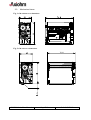
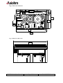
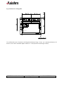
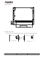
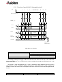
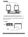
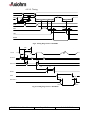
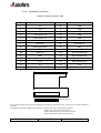
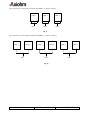
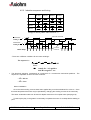
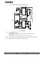
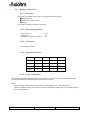
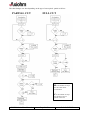
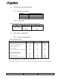
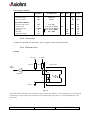
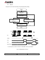
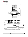
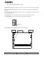
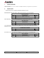
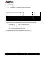
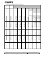
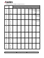
THERMAL PRINTER MECHANISM
Mini-Printer
CM-RMBC
CM-RMDG
User Manual
Reference 3105978-Z
April 2000
AXIOHM, 1-9 Rue d’Arcueil
92120 Montrouge, France
Tel : (33) (0) 1 47 46 78 00 Fax (33) (0) 1 47 46 78 76
1 / 43
IMPORTANT
This manual contains the basic instructions to run your printer. Read it
carefully before using your printer paying full attention to section concerning
recommendations .
CM-RM Series User Manual
Page 2/43
Ref: 3105978 Z
TABLE OF CONTENTS
1. UNPACKING
5
2. OVERVIEW
5
3. MECHANICAL SPECIFICATIONS
6
3.1.
General description
6
3.2.
Dimensions of the complete mechanism :
6
3.3.
Mechanical views
7
4. ELECTRICAL SPECIFICATIONS
11
4.1.
Nominal Power supply
11
4.2.
Nominal Consumption
11
4.3. Description of printhead
4.3.1.
Function of each 64 bit IC (integrated circuit)
4.3.2.
Operation of the complete module
4.3.3.
Electrical specifications of 64-BIT LSI driver
4.3.4.
Printhead Connection
11
12
13
14
17
4.4. Unipolar paper feed motor
4.4.1.
General specification
4.4.2.
Connection
4.4.3.
Induction sequence
19
19
19
19
4.5. Bipolar paper feed motor
4.5.1.
General specification
4.5.2.
Connections
4.5.3.
Induction sequence and timing
4.5.4.
Bipolar stepping motor electric control
20
20
20
21
22
4.6. Bipolar cutter motor
4.6.1.
Overview
4.6.2.
General specification
4.6.3.
Connection
4.6.4.
Induction sequence
4.6.5.
Cutter Initialisation
4.6.6.
Cutter Motor Acceleration Ramp-Up
4.6.7.
Cutter Driving Chart
23
23
23
23
23
23
25
25
4.7. Cutter micro-switch specifications
4.7.1.
General specification
4.7.2.
Connection
27
27
27
4.8. Opto-sensor specification
4.8.1.
Electrical characteristics
4.8.2.
Connection
4.8.3.
External circuit
27
27
28
28
CM-RM Series User Manual
Page 3/43
Ref: 3105978 Z
5. PRINTER CONTROL TECHNIQUES
29
5.1.
Mode 1
29
5.2.
Mode 2
30
5.3.
Mode 3
31
6. RECOMMENDATIONS
32
6.1.
Mechanical recommendations
32
6.2.
Housing design recommendations
32
6.3.
Energising & de-energising printer
32
6.4.
Printing recommendations
32
6.5.
Recommendations for paper
33
6.6.
General
33
6.7.
Cleaning recommendations
33
6.8.
Special recommendation for cutter
34
7. PAPER SUPPLIERS
35
8. SPARE PARTS
35
9. APPENDICES
36
9.1.
APPENDIX 1 : THERMISTOR SPECIFICATIONS
36
9.2.
APPENDIX 2 : Paper specification
38
9.3.
APPENDIX 3 : Heating time and historical control
39
9.4.
APPENDIX 4 : CHANGE PRINTHEAD
42
9.5.
APPENDIX 6 : PRODUCT NAME & CODIFICATION
43
CM-RM Series User Manual
Page 4/43
Ref: 3105978 Z
1.
UNPACKING
Each printer mechanism is packaged in an antistatic bag. Observe precautions for handling in
electrostatic protected areas.
2.
OVERVIEW
Based on static thermal printing technology, the RM series is a family of user-friendly, highly reliable
devices which have been specially designed to fit in the minimum space.
CMxx : Printer only or printer with optional tear bar cover
RMxx : Printer with robust guillotine cutter
Very small size printer and cutter
Silent mechanism
Option of 4 dots/mm or 8 dots/mm print-heads
Easy to connect (only one connector for motor, printhead, opto-sensor and cutter)
Front and bottom paper introduction possible
SUMMARY OF PRINTER SPECIFICATIONS
ITEM
VALUE
CM-RMBC
Printing method
Number of resistor dots
Resolution
UNITS
CM-RMDG
-
Static thermal dot line printing
-
192
384
-
4
8
Dots/mm
Printing width
48
mm
Paper width
60
mm
By Thermistor
-
Head temperature detection
Number of steps / dot line
Paper feed / dot line
2
1
-
0.250
0.125
mm
Paper empty detection
Operating voltage range Vcc (logic)
Opto-sensor
-
4.75-5.25
V DC
Operating voltage range Vch (dot)
20 - 28
20 - 26.4
V DC
Peak printhead current
(all dots ”on ” at nominal value )
8.25
8.8
A
Current consumption:
V ch (at nominal value)
43
23
mA per resistor dot ”on ”
Current consumption:
V cc (at nominal value)
160
100
µA
CM-RM Series User Manual
Page 5/43
Ref: 3105978 Z
Current consumption:
Stepping motor for paper feed
320 (600 bipolar)
mA
Current consumption:
Stepping motor for cutter
500 (1000 bipolar)
mA
- 20 to + 60
°C
Storage range
-10 to 50 for CMBC
Operating range
0 to 50 for CMDG
°C
0 to +50 version with cutter RM**
1.2 × 10⁸ xMBC
108 xMDG
pulses
Mechanical life time*
50
50
Km
Relative Humidity (operating)
20 to 85 no condensing
%
2320061 / WS 752-57 (60µ)
Axiohm reference / Arjo Wiggins
Maximum paper thickness
80
µ
Cutter life time (RMxx)
1 000 000 cuts (with paper 2320061)
Electrical life time*
Recommended paper
* Per AXIOHM standard test conditions (which are mainly : 24V, 25°C, dot printing duty cycle = 30 %)
3.
MECHANICAL SPECIFICATIONS
3.1.
General description
The mechanism consists in :
- Plastic chassis
- Robust guillotine cutter (with relevant motor and switch) for RM versions
- Stepping motor
- Gear train
- Printhead
- End of paper opto-sensor
3.2.
Dimensions of the complete mechanism :
Height :......................................
Depth :.......................................
Width (without rewinder option)..
Weight :.....................................
CM-RM Series User Manual
32 (CMxx) / 36 (CMxx with cover) / 42.1 mm (RMxx)
61 (CMxx) / 62.5 (CMxx with cover) / 65.75 mm (RMxx)
74.5 (CMxx) / 74.5 mm (RMxx)
140 (CMxx) / 250 g (RMxx)
Page 6/43
Ref: 3105978 Z
3.3.
Mechanical views
Fig. 1 CM without cover dimensions
Fig. 2 CM with cover dimensions
CM-RM Series User Manual
Page 7/43
Ref: 3105978 Z
Fig. 3 Side view with cover
10.1
42.1
32
1.75
61
64
Fig. 4 front view with cover
74.5
CM-RM Series User Manual
Page 8/43
Ref: 3105978 Z
Fig. 5 bottom view / fixing holes
Use self threader screws for plastic, the fixing holes diameter being 2.5 mm, use a maximum diameter of 3
mm for screws and a maximum depth in chassis of 7 mm (from the external edge of holes).
CM-RM Series User Manual
Page 9/43
Ref: 3105978 Z
Fig. 4 cutter top view
12.5
paper exit wdth : 60.5
Fig. 5 Opto- sensor position
The position of the end of paper opto-sensor relatively to the paper allows top off form detection
Paper sensitive layer
Paper non sensitive layer
7
7
paper path
direction
5
5.5
front paper inlet
CM-RM Series User Manual
rear paper inlet
Page 10/43
Ref: 3105978 Z
4.
ELECTRICAL SPECIFICATIONS
4.1.
Nominal Power supply
Printer
4.2.
CM-RMBC
CM-RMDG
Printhead :
Logic (Vcc)
Dot line
5
24
V DC
V DC
Stepping motor
24
V DC
Nominal Consumption
Printer
Printhead :
Heating
current / dot
(Vch) at nominal values
RMBC
RMDG
Units
43
23
mA
Logic current / dot (Vcc)
160
100
µA
Stepping Motor (2 activated
phases) for paper feed
Stepping Motor (2 activated
phases) for versions with
cutter (RMxx)
Maximum instantaneous
current per dot line (at 24V)
4.3.
Units
320 unipolar
600 bipolar
mA
1000 bipolar
mA
8.25
8.8
A
Description of printhead
Printer
CM-RMBC
CM-RMDG
UNIT
3
6
-
Nominal dot resistance
530 (± 15 %)
1000 (± 3 %)
ohms
Nominal dot energie
(in standard conditions)
2.0
0.8
mJ
8
8
cm/sec
Driver chips
(64 bit BiCMos LSI)
Max printing speed (with 24V
power supply)
(with dot historical control)
CM-RM Series User Manual
Page 11/43
Ref: 3105978 Z
4.3.1. Function of each 64 bit IC (integrated circuit)
Vch
1
2
3
4
...... (OUTPUTS)....
62
63
64
Line of resistor dots -
Output
Enable (OE)
OE1
OE2
Strobe
64 bits buffer
registers
Serial
Input (SI)
64 bits shift
registers
CLOCK
SERIAL
OUTPUT (SO)
Fig.6 Driver IC schematic
These circuits are supplied by
Each circuit features
Each circuit controls
5V +/- 5% logic voltage
64 open collector transistors
64-bit shift register
64-bit memory register
64 resistor dots on the printhead
The heating element power supply VCH is not connected to the Driver ICs but only to the resistive line
of dots itself. The driver ICs are connected via a pattern of high current gold interconnecting traces to the
line of resistor dots.
The dot line is of the interdigitated type, in order to maintain the tight definition of the dot geometry
and resistance. In such a scheme the heating element power supply VCH forms a ‘comb’ of traces over
which the resistive line of dots is laid. The outputs of the driver ICs form a second comb interdigitated with
the first.
CM-RM Series User Manual
Page 12/43
Ref: 3105978 Z
4.3.2. Operation of the complete module
R1
Resistors
R64
R1
Resistors
CHIP
1
SI
R 64
CHIP
N
SO
SI
SO
OUT
OE (2N-1)
OE 2N
CLK
STROBE
IN
OE 1
OE 2
Fig.7
- Data to be printed is clocked into a shift register formed by cascading "n" chips.
- E.g. 384 dot head uses 6 chips with the SO output of chip 1 used as the SI input for chip
2 etc. Respectively, the SO output of chip 2 is used as the SI input for chip 3 etc.
After 384 clocks, the initial piece of data entered corresponds to the last (384th) dot of the
line (the R64 output of the 6th chip). The last bit of data entered will correspond to the first
dot of the line(R1 of the first chip).
Line of
dots
R1 of chip 1
Printhead
substrate
R1 of chip 1
chip
1
chip
n
Sensitive layer
Printhead
bottomview
paper side
paper feed
direction
Thermal paper
Fig.8 Routing of data to the resistor dots
CM-RM Series User Manual
Page 13/43
Ref: 3105978 Z
4.3.3. Electrical specifications of 64-BIT LSI driver
4.3.3.1. General
CM-RMBC
MIN
MAX
-0.5
28
-0.5
7
- 60
- 2.9
PARAMETER
Max.voltage at outputs 1 to 64
Max.input voltage
Max.output current/dot*
Total max.output current *
CM-RMDG
MIN
MAX
26.4
Vch
-27.3
-1.7
UNIT
V
V
mA
A
*64 × 60 mA × 0.75 % = 2.9 A ( for RMBC )
4.3.3.2. Other
The specifications given below are given for the following conditions :
- Room temperature
- Logic voltage on chip :
- Clock frequency :
Logic Current (5 V)
Current per controlled element (dot)
Min.high-level input voltage
Max.low-level input voltage
Max.high-level input current
Max.low-level input current
Min.high-level output voltage
Max.low-level output voltage
Max.high-level output current
Max.low-level output current
Heating current (xMBC)
Max.power output current
Max.output leakage
current
Max.output voltage
Deviation for Vdonmax
CM-RM Series User Manual
4.75 V < Vdd < 5.25 V,
10 MHz (CM-RMBC) / 4MHz (CM-RMDG).
CM-RMBC
Conditions
Values
Vdd = 5V
160 µA
2.8V
0.8 V
+/-10µA
+/-10 µA
Io = Iohmax 2.8 V
Io = Iolmax 0.4 V
0.1 mA
-0.5 mA
RM-RMDG
Conditions
Values
Vcc = 5V
0.7Vcc
0.3 Vcc
Vcc ≤ 5V
0.5µA
0.5µA
Vcc = 4.5
4.45 V
Vcc = 4.5
0.05 V
-
Symb
Idd
Vih
Vil
Iih
Iil
Voh
Vol
Iohmax
Iolmax
Conditions
Vdon=Vdonmax
Vdon=24 V
Values
-60 mA
1 µA
Symb
Idomax
Idoleak
Idout=Idomax
1300 mV
200 mV
Vdonmax
dVdon
Page 14/43
Ref: 3105978 Z
4.3.3.3. Timing
DIN
Tsdc
CLK
Thdc
Tr
Tf
Tclk
Tst
Tscl
Tdos
Tdoec
Tdcoe
Tdoec
Tdcs0
SO63
Tdoedo
Tfdo
Tddooe
Trdo
STB
OEx
DOUTx
Fig.9 Timing Diagram for CM-RMBC
Tclk
t2
Clock
t3
t4
Serial in
t7
t7
Serial out
t6
t5
Strobe
OEn:
t8 t9
t8
t10
Data Out n :
90%
10%
90%
10%
Fig.10 Timing diagram for CM-RMDG
CM-RM Series User Manual
Page 15/43
Ref: 3105978 Z
CM-RMBC
CM-RMDG
Description
Min
Min
Serial clock period
Rise, fall time f clock, 10% -> 90%
Clock to OE delay time
OE to clock delay time
Data in to clock setup time
Data in from clock hold time
Serial data out from clock delay *
Serial data out from clock delay **
Clock to strobe delay time
Strobe high time
Strobe to OE delay time
OE to data out delay time ***
Data out fall time, 10% -> 90% ***
OE to data out delay time ***
Data out rise time, 10% -> 90% ***
100
Sym
Tclk
Tr, Tf
Tdoec
Tdcoe
Tsdc / t3
Thdc / t4
Tdcs0 / t7
Tdcs1
Tscl / t6
Tst / t5
Tdos
Tdoedo / t8
Tfdo / t9
Tddooe
Trdo / t10
Max
250
50
10
10
10
100
20
20
80
110
100
100
-
100
100
100
0.25
1
1
1
Max
-
120
-
2
0.5
2
Un
it
ns
µs
µs
ns
ns
ns
ns
ns
ns
ns
ns
µs
µs
µs
µs
*, **, *** have to be considered only for CM-RMBC
*
**
***
10 pf load on output, all inputs Vil = Vss + 0.5V Vih = VDD - 0.5V.
10 pf load on output, standard Vil and Vih.
Vdd = 5V, Temp = 25°C, with a resistant load, R1 = 500 Ω , connected to 24V.Can not be
measured. These parameters will be assured by design after characterisation of the prototypes.
TIMING RESTRICTIONS (CM-RMBC)
- No clock transistions may take place during Tscl, tst, Tdoes, Tdoec,and Tdcoe,
- Data input must change on the falling edge of the clk-input,
- Data must be stable during Tsdc, Tr and Thdc.
CM-RM Series User Manual
Page 16/43
Ref: 3105978 Z
4.3.4. Printhead Connection
PINOUT OF ZIF 30 CONNECTOR
PIN N°
SIGNAL
PIN N°
SIGNAL
1
Vch
16
GND
2
Vch
17
GND
3
Cutter motor B2
18
GND
4
Cutter motor B1
19
GND
5
Cutter motor A1
20
GND
6
Cutter motor A2
21
Thermistor 1
7
Switch Out
22
Thermistor 2
8
Anode Opto-sensor
23
OE1
9
Collector Opto-sensor
24
Data In
10
Data Out
25
Paper feed motor B2
11
Clock
26
Paper feed motor B1
12
Strobe
27
Paper feed motor A2
13
OE3
28
Paper feed motor A1
14
Vcc
29
Vch
15
OE2
30
Vch
1
30
connector ZIF 30
This connector (fitted on your printer) should be connected to your board with a 30 pins flex to another compatible
connector.
Compatible connectors suppliers and references : Molex 5597 3951 3304 straight connector
: Molex 5597 3951 3303 bent connector
: Stocko MZF 9390 60 3030 straight connector
: Stocko MZF 8900 60 3030 bent connector
CM-RM Series User Manual
Page 17/43
Ref: 3105978 Z
Chip connection for 4 dots/mm print-head CM-RMBC ( 3 chips to connect )
CHIP 1
CHIP 2
CHIP 3
OE 1
OE 2
OE 3
Fig.11
Chip connection for 8 dots/mm print-head CM-RMDG ( 6 chips to connect )
CHIP 1
CHIP 2
OE 1
CHIP 3
CHIP 4
OE 2
CHIP 5
CHIP 6
OE 3
Fig.12
CM-RM Series User Manual
Page 18/43
Ref: 3105978 Z
4.4.
Unipolar paper feed motor
4.4.1. General specification
- Operating range :
- Coil resistance :
- Number of phases :
- Drive method :
- Current drawn
- Maximum starting frequency
- Steps to initialize paper feed
- Step angle :
- Number of steps per revolution :
20V < V < 28V (24V nominal)
150 Ω ± 10%
4
2 phases on
160 mA per phase
500 pps
4
7° 30 ‘
48
Acceleration table : this motor takes 20 steps to reach its maximum speed ( 1600 µs which means
600 pps and 75 mm/s). In this table the first row shows the motor pitch and the second one shows
the motor phase time in µs.
1
2000
2
1997
3
1990
4
1981
5
1967
6
1950
7
1930
8
1908
9
1883
10
1858
11
1832
12
1806
13
1781
14
1757
15
1734
16
1715
17
1698
18
1683
19
1674
20
1667
4.4.2. Connection
Connection to the PCB
PIN n°
1
2
3
4
5
6
Wire color
black
brown
yellow
orange
Motor
A1
A2
B2
B1
empty
red
COM
A1
A2
B2
Com
B1
The PCB is then connected to the flexible containing all supply and control, see page 16.
4.4.3. Induction sequence
BLACK
BROWN
ORANGE
YELLOW
RED
RED
Step 1
Step 2
-
-
Step 3
-
Step 4
-
+
-
Voltage on cable is negative where shown as “–
Otherwise cable is floating except if shown as
CM-RM Series User Manual
Page 19/43
Ref: 3105978 Z
External circuit
Examples :
1 when clamping diode is not integrated to the stepper motor driver
2 when clamping diode is integrated to the stepper motor driver
Vch (24V)
1
Vch (24V)
Motor winding
Vch (24V)
Motor winding
Zener diode
24V
Clamping diode
Stepper
Motor
Driver
Vch (24V)
2
Zener diode
24V
Stepper
Motor
Driver
Note : If the phase currents are switched to zero, the position in the sequence must be memorised.
When the winding currents are re-applied the polarities corresponding to the last known position
should be used. This ensures that the motor will re-start correctly. (this is still true for next chapter
(bipolar motor))
4.5.
Bipolar paper feed motor
An optional bipolar motor is available for paper feed
4.5.1. General specification
- Recommended control voltage :
- Coil resistance :
- Number of phases :
- Step angle :
- Paper feed for one printing line :
- Recommended control current :
- Maximum starting frequency :
24V
20 Ω ± 10%
4
7° 30'
2 (CMBC) / 1 (CMDG)
300 mA (peak)
500 pps
4.5.2. Connections
PIN n°
1
2
3
4
5
6
Wire color
black
brown
yellow
orange
empty
empty
Motor
A1
A2
B1
B2
A1
B1
A2
B2
Wire length
60 ± 10 mm
Connection to flexible
CM-RM Series User Manual
Page 20/43
Ref: 3105978 Z
4.5.3. Induction sequence and timing
BLACK
YELLOW
BROWN
ORANGE
STEP 1
STEP 2
STEP 3
STEP 4
Voltage on cable is negative where shown as “-“.
Voltage on cable is positive where shown as “+”.
current into
winding A
current into
winding B
+
0
0
Currents removed
t1
+
t2
Currents
restored
Motor Steps
- There are 4 different conditions for the motor windings:
The sequence is :
AB
AB
AB
AB
AB
Where
AB
stands for “A is positive
and B is negative” etc.
• This electrical sequence corresponds to a sequence of 4 consecutive mechanical positions. The
sequence is repeated 12 times for each revolution.
- t1 = 0.4 ms
- t2 = 2 ms
Motor initialisation
Once the initial winding currents have been applied they must be maintained for a time t1. Once
this time has passed the motor may be operated by changing the winding currents in the usual way.
The same acceleration table can be used for bipolar motor than for unipolar motor (see page 18)
To take-up the play in the gears it is necessary to operate the motor for 16 steps before starting to
print.
CM-RM Series User Manual
Page 21/43
Ref: 3105978 Z
4.5.4. Bipolar stepping motor electric control
820 pF
16
1
56 kΩ
1k
PBL
3717
Phase A
I0 A
9
8
820pF
Rs A2 A1
I1 A
24 V
+5V
stepper
motor
B2
B1
820 pF
From µprocessor
16
1
56 kΩ
1k
PBL
3717
Rs
Phase B
I0 B
8
9
820pF
I1 B
Fig.13 Example
Note 1 : Rs : resistors of 0.8 ohm
with I0A and I0B = 1 and
I1A and I1B = 0 --->I = 0,3 A (the required control current for paper feed).
with I0A and I0B = 0 and
I1A and I1B = 0 --->I = 0,5 A (the required control current for cutter).
Note 2 : to optain 0.8 Ω (which is not standard) it is possible to set 1Ω and 4.75Ω in parallel.
- For other stepping motor control requirements, please contact us.
CM-RM Series User Manual
Page 22/43
Ref: 3105978 Z
4.6.
Bipolar cutter motor
4.6.1. Overview
The cutter is mounted to the printer cover and includes parts below :
n Stepping motor
n Cutter drive wheel & rack
n Switch
This cutter can achieve partial or total cuts
4.6.2. General specification
- Coil resistance :
- Step angle :
- Number of steps per revolution :
8Ω
15°
24
4.6.3. Connection
Connected to the PCB
4.6.4. Induction sequence
A1
A2
B1
B2
Step 1
-
+
-
+
Step 2
-
+
+
-
Step 3
+
-
+
-
Step 4
+
-
-
+
4.6.5. Cutter Initialisation
The sequence described next page with logic chart allows the cutter to be well positioned when the
system (mechanism & controller board) is powered on (or reset).
Notes :
- The logic chart is designed to place the cutter in the middle of the "closed switch area".
- When ten additional steps in are achieved after a switch status reading, this avoid reading mistake
due to switch bounce.
CM-RM Series User Manual
Page 23/43
Ref: 3105978 Z
Cutter initialisation logic chart :
Read switch status ( and set step counter to 0 )
switch closed
no
yes
Start Motor step at 2ms (forward feed)
no
switch
opened
yes
Achieve 10 more steps (forward feed)
Step backward (at 2 ms)
no
switch closed
yes
Step backward (at 2 ms)
Step Counter = Step Counter + 1
no
switch
opened
yes
Achieve 10 more steps (backward feed)
Step forward (at 2 ms)
no
switch closed
yes
Achieve "step counter/2" steps forward
Stop
CM-RM Series User Manual
Page 24/43
Ref: 3105978 Z
4.6.6. Cutter Motor Acceleration Ramp-Up
The cutter can be started with a motor step time of 2 ms, then the speed can be increased by reducing this
cycle time up to 1 ms following the curve given here after.
Step
Time (µs)
1
2000
2
2000
3
2000
4
2000
5
2000
6
1800
7
1660
Step
Time (µs)
9
1420
10
1330
11
1250
12
1170
13
1110
14
1050
15
1000
8
1530
Notes :
- This curve uses 2000µs on the first 5 steps, this does not correspond to an acceleration but to a
routine applied in the next logic chart (where "step (n)" means one motor step is achieved with the
step time given above).
- This acceleration ramp up can be used either for forward or backward blade movement.
4.6.7. Cutter Driving Chart
This first chart allows to start the cutter with the acceleration ramp up previously given (for motor step time).
set n = 0 & c = 0
Start motor (at 2ms) : step (1)
n=n+1
yes
switch closed
yes
step (n+1)
n<15
no
no
step (15)
n = n +1
yes
step (n+1)
c = c +1
n < 15
no
c=c+1
step (15)
yes
c < 148
no
no
yes
see Partial Cut chart
CM-RM Series User Manual
partial cut
Page 25/43
see Full Cut chart
Ref: 3105978 Z
The chart changes now here depending on the type of cut required : partial or full cut.
PARTIAL CUT
FULL CUT
n is the number of steps
for the cutter motor
acceleration.
c is the number of steps
for the total cycle of
partial or full cut.
CM-RM Series User Manual
Page 26/43
Ref: 3105978 Z
4.7.
Cutter micro-switch specifications
4.7.1. General specification
Reference
Contact resistance
Maximum Current
Maximum Rating
4.7.2.
DB3A-A1BA Switch Cherry
50 mΩ
Ω Maximum.
0,1A - 125 V AC ( UL V0 )
2 000 000 Open-Close cycles
Connection
Connected to the PCB with cutter motor and integrated to the flexible
Wires
Contact Status
Open
‘guillotine’ blade
Closed
Closed
Open
White / White
4.8.
Opto-sensor specification
4.8.1. Electrical characteristics
Absolute Maximum ratings
SYMBOL
RATING
UNIT
If
50
mA
Pulsed forward current *
IFP
1
A
Reverse voltage
VR
5
V
P
75
mW
VCEO
30
V
Collector Current
IC
20
mA
Collector Dissipation at 25°C max
PC
50
Mw
LED
Continuous Forward Current
Max. Power Dissipation at 25°C max
PHOTO-TRANSISTOR
Collector Emitter Voltage
* (Time On, Time Off) T On = 100µs, T On + T Off = 10 ms
Note : Driving the sensor with pulse current allows to use higher current to improve paper detection.
CM-RM Series User Manual
Page 27/43
Ref: 3105978 Z
Input/Output Conditions
SYMBOL
CONDITIONS
VF
IR
IF=10 mA
VR=5v
ICE0
IL
ICE0D
tr
tf
λp
VCE=10V
VCE= 5V, IF=10mA
VCE= 5V, IF=10mA
VCE= 2V, IC=100µA
RL= 1kΩ
Ω
LED
Forward voltage
Reverse current
TRANSFER CHARAC.
Collector dark current
Light Current
Leakage Current
Rise time
Fall time
Peak wave length
Min.
TYP.
Max.
UNIT
1.3
10
V
µA
200
nA
µA
nA
µs
µs
nm
90
200
30
25
940
4.8.2. Connection
Connected to the PCB, the opto-sensor is then clipped in front or bottom position
4.8.3. External circuit
Example
Vcc (5V)
10 kΩ
CPU *
PORT
5V pulse
Opto-sensor
68 Ω
1
green
2
orange
74HC04
3
black
GND
Fig. 14
* Rise time and fall time depend on the voltage and current driving conditions. In the example above we recommend
to measure the sensor response 300 µs after the current leading edge of the pulse (or current establishment) in the
sensor LED.
CM-RM Series User Manual
Page 28/43
Ref: 3105978 Z
5.
PRINTER CONTROL TECHNIQUES
Printer control techniques in order to operate the printer. We depict hereafter three possible modes.
5.1.
Mode 1
- The paper feeds itself automatically during the heating cycle thereby permitting a high speed to be
achieved. (in this mode, it is recommended to use historical control, see page 35)
Printing of n
dot line
Transmission of data
in series (Din)
in step with CLK
Transfer to
memory
stage (STROBE)
Heating controlled
through
OE 1,OE 2,...OEn
simultaneously
Transmission of next
series of data
Motor
feed
1 to n
End of
printing
CLK
T
Din
N
Strobe
OE 1
OEn
Motor Steps
T : Clock frequency 10 MHz maximum for CM-RMBC / 4MHz for CM-RMDG
Fig. 15 Timing diagram for mode 1
CM-RM Series User Manual
Page 29/43
Ref: 3105978 Z
5.2.
Mode 2
The paper feed occurs after the heating cycle giving high quality printing.
Printing of n
dot line
Transmission of data
in series (Din)
in step with CLK
Transfer to memory
stage (STROBE)
Heating controlled
through
OE 1,OE 2,...OEn
simultaneously
Transmission of next
series of data
Motor feed
1 to n
End of
printing
CLK
T
Din
N
Strobe
OE 1
OEn
Motor Steps
T : Clock frequency 10 MHz maximum for CM-RMBC / 4MHz for CM-RMDG
Fig. 16 Timing diagram for mode 2
CM-RM Series User Manual
Page 30/43
Ref: 3105978 Z
5.3.
Mode 3
This mode is used in conditions where there is a limit of electrical current. The dot line is printed in
stages heating only a portion of the line at a time, effectively giving reduced consumption.
Printing of
n dot line
Transmission of data
in series (Din)
in step with CLK
Transfer to memory
stage (STROBE)
Heating controlled
through
OE 1,OE 2,...OEn
successively or in blocks
Transmission of
next series of data
Motor feed
1 to n
End of
printing
Clock CLK
T
Din
(serial input)
N
N
Strobe
OE 1
OEn
Motor Steps
T : Clock frequency 10 MHz maximum for CM-RMBC / 4MHz for CM-RMDG
Fig. 17 Timing diagram for mode 3
CM-RM Series User Manual
Page 31/43
Ref: 3105978 Z
6.
RECOMMENDATIONS
6.1.
Mechanical recommendations
Never apply mechanical stress to the printer, this could result in misalignment and thus degradation of the
print quality.
The thermal printhead must have 1 degree of freedom. Never hinder the printhead from pivoting on its axis.
6.2.
Housing design recommendations
Forecast space for paper guide to use one of the two possible paper inlets (or both)
When the front paper inlet is used, we recommend an additional paper guiding to facilitate correct paper
introduction.
See the fixation position, make sure it is easy enough to release printer, this operation is necessary for easy
maintenance (change of printhead for example)
Space to open cover : the cover (which contains the cutter) is strongly clipped, it is necessary to leave enough
place to catch it in order to open it.
6.3.
Energising & de-energising printer
When energising the thermal printhead (Vcc, 5 V) it is important to apply all the logic signals within 10 ms
(particularly to de-energise all the OEs).
If the line of dots (Vch, 24 V) is supplied before the control logic, resistor dots may be destroyed. Because
the control logic has a random state, resistors might be heated for a longer period than the specified
maximum, burning out the heated resistor.
To avoid this, we recommend applying the heating voltage (Vch) after the logic supply voltage (Vcc, 5V).
The same precaution should be taken when shutting down. The supply voltage Vch must be switched off
before the logic supply voltage Vcc. Care should be taken to allow enough time for residual capacitive
charge to dissipate.
6.4.
Printing recommendations
n In order to avoid excessive noise from the stepper motor, avoid using it at the following frequencies :
between 150 and 250 pps (for better printing quality, avoid fast speed variations).
n To avoid the paper feed motor temperature rise, use a time ratio of 2 "on" 3 "off" up to 2 minutes
maximum of continuous printing.
Examples : 2 seconds "on" followed by 3 seconds "off", 20 seconds "on" followed by 30 seconds "off".
CM-RM Series User Manual
Page 32/43
Ref: 3105978 Z
6.5.
Recommendations for paper
n As paper roll bearing, use an AXIOHM reference (or approved by) .
n Use a paper roll of maximum diameter 80 mm when paper slides on its bucket, this value can be overshot
up to 120 mm when paper roll is mounted on a friction-less axis (the maximum diameter also depends on
the acceleration ramp up because of inertia).
n Leave the paper stock spool free to turn.
n The printer should not operate without paper as this will damage the surface of the platen.
n Paper with bad factor may affect the printhead life.
6.6.
General
n Ensure that there is adequate air circulation around the printhead support/heatsink as poor ventilation of
n
n
n
n
n
n
n
n
n
the printhead can degrade the print quality.
Never open the cover whilst the cutter is operating.
Never introduce tools inside the printer, wires could be de-soldered or short circuited.
It is very important that the printhead support/heatsink is connected to the customer appliance chassis
(see p16 pinout connection GND).
Ensure that the cutter blades are in the correct position before use in order to ensure that they do not
deteriorate.
when continuous printing is performed, the supply energy should be reduced so that the head temperature
monitored through the thermistor will remain below the maximum temperature.
When setting ‘power on / power off’, strobe (STR) shall be on ‘disable’.
Heat elements and IC’s shall be anti-electrostatic in order to prevent electrostatic destruction. Do not
touch the connector pins with fingers.
Make sure no foreign particles roll on the head surface, this would cause damage.
If condensation occurs, do not switch on the printer until it has disappeared.
6.7.
Cleaning recommendations
The CM/RMBC and CM/RMDG mechanisms are high reliable units which require very little maintenance
but may benefit from cleaning as detailed below.
Depending on the environment in which the printer is used , the printer can accumulate dust. Therefore it is
necessary to clean it periodically in order to maintain a good print quality. The cleaning period is dependant
on the environment and the usage of the printer, but the printhead should be cleaned at least once a year or
up to one month in heavy duty applications. The printhead should always be cleaned immediately if the print
becomes visibly fainter due to its contamination.
Cleaning Instructions :
- Switch off printer. Never clean the head immediately after printing, the head may be hot.
- Open the printer cover and remove the paper from its slot.
- Clean the heating dots of the head with a cotton stick containing a solvent alcohol (ethanol,
methanol, or IPA) but do not touch the printhead with your fingers !
- Allow the solvent to dry.
- Reload the paper and close cover.
N.B
AXIOHM is able to provide cleaning kits Ref : CK60000A
CM-RM Series User Manual
Page 33/43
Ref: 3105978 Z
6.8.
Special recommendation for cutter
Mechanical stress should not be applied to the cutter cover, it would lead to a blade movement perturbation.
Make sure the ground is connected. Ground must stay connected while operating and manipulating the
cutter cover.
Do not keep the cutter motor phase "on" while the cutter is not operating (this would also lead to an
increasing motor temperature).
To avoid paper jam, it is recommended to feed 2 mm of paper (16 motor steps) after cutting.
A vertical position, as shown on next drawing, is better for paper dust elimination.
paper exit
To release blades in case of jam, use the wheel shown on next drawing :
wheel available
from the side
CM-RM Series User Manual
screw wheel available
from the top
Page 34/43
Ground
connection
Ref: 3105978 Z
7.
PAPER SUPPLIERS
ARJO WIGGINS Ref : S752-57 (2320061 in AXIOHM classification) (see appendix 2 for specifications)
8.
SPARE PARTS
All spare parts for kits are supplied as individually packaged loose parts.
Mechanism Kits : Those kits contain : chassis, paper feed motor, gear train and platen.
MECHANISM KITS
REF
3103166
3103223
DESIGNATION
Mechanism Kit for CM/RM** (unipolar motor)
Mechanism Kit for CM/RM** (bipolar motor)
QTY
1
1
Print- head Kits : those kits contain the print-head, the flexible and the opto-sensor.
PRINT-HEAD KITS
REF
3103168
3103169
DESIGNATION
Print-head Kit for CM/RMBC (4 dots/mm)
Print-head Kit for CM/RMDG (8 dots/mm)
QTY
1
1
Cover with cutter kit : this kit contains the guillotine cutter, the cutter motor, and the cutter switch all
integrated to the cover
COVER WITH CUTTER KIT
REF
3105976
DESIGNATION
Cover Kit with cutter and Bipolar motor
QTY
1
Flex cable kit : those cables (10 per kit) are designed to connect the printer to its controller board
FLEX CABLE KIT
REF
3103578
CM-RM Series User Manual
DESIGNATION
Standard flex cable adapted to ZIF connections
Page 35/43
Ref: 3105978 Z
QTY
10
9.
APPENDICES
9.1.
APPENDIX 1 : THERMISTOR SPECIFICATIONS
GENERAL CHARACTERISTICS
xMBC
xMDG
Climatic category (IEC) 40/85/56 (for xMBC)
Maximum operating temperatures
-55° C to + 150° C
-20° C to + 80° C
Rated resistance at 25° C
Rn (see table of values)
Tolerance for Rn
5%
Maximum dissipation at 25° C
P max = 0,24 mW
Thermal dissipation factor
_ = 4 mW/°C
_ = 5 mW/°C
Thermistor time constant/dot line
t = 7 sec
t = 30 sec
Resistance value as a function of temperature (see curves)
This thermistor has a rated value of 100 kΩ
Ω . Its resistance variation can be expressed as follows :
R = Rn exp B (
1
T
1 )
Tn
where T is in kelvin degrees (°K)
B = 4170° K (for xMBC) / 4066° K (for xMDG)
Rn = reference value at temperature Tn (295° K)
The main specifications of the thermistor are listed in the following pages.
NTC thermistor, rectangular size (IEC 12.05), silver palladium metallic coating.
CM-RM Series User Manual
Page 36/43
Ref: 3105978 Z
APPENDIX 1 (Contd.)
RESISTANCE/TEMPERATURE VARIATION for CM-RMxx
CM-RM Series User Manual
Page 37/43
Ref: 3105978 Z
9.2.
APPENDIX 2 : Paper specification
Paper WS 752-57 (ref 2320061 in Axiohm classification for 5 cm diameter roll)
Property
Gramms
Thickness
Surface
smoothness
Brightness
Whiteness
Opacity
Method
ISO 536
ISO 534
ISO 5627 (Beckk)
Unit
g/m2
µm
sec
Value
56 +/- 3
61 +/- 4
300 min
%
OD
%
91 min
0.09 min
83 min
Tensile strength
BNL2
Macbeth RD 914
TAPPI
T425(BNL2)
ISO 1924/1
N/15 mm
Tear Strength
ISO 1974
mN
Colour Image
Saturation Density
Dynamic test
Initiation T°
Saturation T°
Heated platen
Heated platen
Macbeth
RD914
°C
°C
40 min MD
20 min CD
300min MD
33 min CD
Black
1.25 min
Property
Conditions
Heat stability
Moisture stability
60°C, 24 hrs
90% RH-40°C
24 hrs
5000 lux, 100
hrs
Light stability
CM-RM Series User Manual
70 maxi
105-110
Image Loss
(Macbeth
RD914)
10% maxi
5% maxi
Whiteness Loss
(Macbeth
RD914)
0.10 maxi
0.01 maxi
5% maxi
0.01 maxi
Page 38/43
Ref: 3105978 Z
9.3.
APPENDIX 3 : Heating time and historical control
The heating time tables are presented on next pages
The motor cycle time for one dot line is given in the second top line of the table, it is the time for one (or two)
motor step(s).
The column 3 (indicated with : speed <xxx mm/s and motor cycle time > xxx ms) gives the required heating
time, giving the necessary energy to obtain an optical density of 1.2.
Two areas are then defined in tables :
Area 1 : "white"
The motor cycle time for one dot line is greater than the heating time indicated in column 3
Area 2 : high lighted
The maximum heating time is greater than the motor cycle time
Note : when the required heating time (function of speed, voltage and temperature) becomes greater than the
motor cycle time, printer cannot be operated. This does not occur for xMxx printers at voltages and speeds
indicated in this manual.
How to use tables ?
heating time can be controlled either with or without historical control.
- Without historical control : apply the indicated heating time given as a function of speed, voltage
and temperature. At high speed, printing quality for isolated dots might be affected with this method.
Example: for CM/RMBC at 70mm/s, 30°C and 24 volts, heating time = 1.26
- With historical control in area 1 : apply the indicated heating time (function of speed, voltage and
temperature) when the dot has been heated on the previous subline, and the time from column 3
when it has not. This method gives the best printing quality.
Example: for xMBC at 50 mm/s, 20°C and 24 volts :
previous dot
dot to heat
Heating time to apply
dot ON
1.57 ms
dot OFF
2.79 ms
- With historical control in area 2 : apply the indicated heating time (function of speed, voltage and
temperature) when the dot has been heated on the previous subline, and the motor cycle time when it
has not. At high speed, printing quality for isolated dots might be slightly affected with this method.
Example: for xMDG at 70 mm/s, 0°C and 22 volts :
previous dot
dot to heat
Heating time to apply
dot ON
0.94 ms
dot OFF
1.79 ms
CM-RM Series User Manual
Page 39/43
Ref: 3105978 Z
Heating time for CM-RMBC (with paper WS 752-57 )
Tension Temp °C
Speed (mm/s)
Volts
R= 518 Ohms
< 5 mm/s 30 mm/s 40 mm/s 50 mm/s 60 mm/s 70 mm/s 75 mm/s
>50 mm/s 8.33 ms 6.25 ms
5 ms
4.17 ms 3.58 ms 3.33 ms
20
20
20
20
20
20
20
-10
0
10
20
30
40
50
22
22
22
22
22
22
22
-10
0
10
20
30
40
50
24
24
24
24
24
24
24
24
-10
0
10
20
25
30
40
50
26
26
26
26
26
26
26
-10
0
10
20
30
40
50
28
28
28
28
28
28
28
-10
0
10
20
30
40
50
30
30
30
30
30
30
30
-10
0
10
20
30
40
50
5.29
4.9
4.51
4.12
3.73
3.33
2.94
4.32
4
3.68
3.36
3.04
2.72
2.4
3.59
3.32
3.06
2.79
2.66
2.52
2.26
1.99
3.03
2.8
2.58
2.36
2.13
1.91
1.68
2.59
2.4
2.21
2.01
1.82
1.63
1.44
2.24
2.08
1.91
1.74
1.58
1.41
1.25
CM-RM Series User Manual
3.49
3.23
2.97
2.72
2.46
2.2
1.94
2.85
2.64
2.43
2.21
2
1.79
1.58
2.37
2.19
2.02
1.84
1.75
1.66
1.49
1.31
2
1.85
1.7
1.55
1.41
1.26
1.11
1.71
1.58
1.46
1.33
1.2
1.08
0.95
1.48
1.37
1.26
1.15
1.04
0.93
0.82
3.2
2.97
2.73
2.49
2.25
2.02
1.78
2.61
2.42
2.22
2.03
1.84
1.64
1.45
2.17
2.01
1.85
1.69
1.61
1.53
1.37
1.21
1.83
1.7
1.56
1.42
1.29
1.15
1.02
1.57
1.45
1.33
1.22
1.1
0.99
0.87
1.36
1.26
1.15
1.05
0.95
0.85
0.75
Page 40/43
2.98
2.76
2.54
2.31
2.09
1.87
1.65
2.43
2.25
2.07
1.89
1.71
1.53
1.35
2.02
1.87
1.72
1.57
1.49
1.42
1.27
1.12
1.7
1.58
1.45
1.32
1.2
1.07
0.95
1.46
1.35
1.24
1.13
1.02
0.92
0.81
1.26
1.17
1.07
0.98
0.89
0.79
0.7
2.79
2.58
2.38
2.17
1.96
1.76
1.55
2.28
2.11
1.94
1.77
1.6
1.43
1.26
1.89
1.75
1.61
1.47
1.4
1.33
1.19
1.05
1.6
1.48
1.36
1.24
1.12
1.01
0.89
1.37
1.26
1.16
1.06
0.96
0.86
0.76
1.18
1.09
1.01
0.92
0.83
0.74
0.66
2.64
2.44
2.25
2.05
1.86
1.66
1.47
2.15
1.99
1.83
1.67
1.51
1.36
1.2
1.79
1.66
1.52
1.39
1.33
1.26
1.13
0.99
1.51
1.4
1.29
1.17
1.06
0.95
0.84
1.29
1.2
1.1
1
0.91
0.81
0.72
1.12
1.03
0.95
0.87
0.79
0.7
0.62
Ref: 3105978 Z
2.57
2.38
2.19
2
1.81
1.62
1.43
2.1
1.94
1.79
1.63
1.47
1.32
1.16
1.74
1.61
1.48
1.35
1.29
1.23
1.1
0.97
1.47
1.36
1.25
1.14
1.03
0.93
0.82
1.26
1.16
1.07
0.98
0.88
0.79
0.7
1.09
1.01
0.93
0.85
0.77
0.69
0.6
Heating time table for CM-RMDG ( with paper WS 752-57 )
Voltage
(Volts)
21
21
21
21
21
21
21
22
22
22
22
22
22
22
23
23
23
23
23
23
23
24
24
24
24
24
24
24
24
25
25
25
25
25
25
25
26
26
26
26
26
26
26
27
27
27
27
27
27
27
Temp °C Speed (mm/s)
R =
970 Ω
<5mm/s
30 mm/s 40 mm/s 50 mm/s 60 mm/s 70 mm/s 75 mm/s
>25 ms
4.17 ms 3.13 ms 2.5 ms 2.08 ms 1.79 ms 1.67 ms
2.27
1.48
1.36
1.26
1.18
1.08
-10
1.11
2.1
1.37
1.26
1.17
1.09
1
0
1.03
1.93
1.26
1.16
1.07
1
0.92
10
0.95
1.76
1.15
1.06
0.98
0.92
0.84
20
0.87
1.59
1.04
0.96
0.89
0.83
0.76
30
0.78
1.43
0.93
0.86
0.79
0.74
0.68
40
0.7
1.26
0.82
0.75
0.7
0.66
0.6
50
0.62
2.06
1.35
1.24
1.15
1.07
0.99
-10
1.02
0.91
0
1.91
1.25
1.15
1.06
1
0.94
1.76
1.15
1.05
0.98
0.92
0.86
0.84
10
1.61
1.05
0.96
0.89
0.84
0.79
0.77
20
1.45
0.95
0.87
0.81
0.76
0.71
0.69
30
1.3
0.85
0.78
0.72
0.68
0.64
0.62
40
1.15
0.75
0.69
0.64
0.6
0.56
0.55
50
0.93
0.9
1.89
1.24
1.13
1.05
0.98
-10
1.75
1.15
1.05
0.97
0.91
0.86
0.84
0
1.61
1.05
0.96
0.89
0.84
0.79
0.77
10
1.47
0.96
0.88
0.82
0.76
0.72
0.7
20
1.33
0.87
0.8
0.74
0.69
0.65
0.64
30
1.19
0.78
0.71
0.66
0.62
0.58
0.57
40
1.05
0.69
0.63
0.58
0.55
0.52
0.5
50
1.73
1.14
1.04
0.96
0.9
0.85
0.83
-10
1.61
1.05
0.96
0.89
0.84
0.79
0.77
0
1.48
0.97
0.89
0.82
0.77
0.73
0.71
10
1.35
0.88
0.81
0.75
0.7
0.66
0.65
20
1.28
0.84
0.77
0.71
0.67
0.63
0.61
25
1.22
0.8
0.73
0.68
0.64
0.6
0.58
30
1.09
0.72
0.65
0.61
0.57
0.54
0.52
40
0.96
0.63
0.58
0.54
0.5
0.47
0.46
50
1.6
1.05
0.96
0.89
0.83
0.79
0.76
-10
1.48
0.97
0.89
0.82
0.77
0.73
0.71
0
1.36
0.89
0.82
0.76
0.71
0.67
0.65
10
1.24
0.81
0.75
0.69
0.65
0.61
0.59
20
1.12
0.74
0.67
0.63
0.59
0.55
0.54
30
1.01
0.66
0.6
0.56
0.52
0.49
0.48
40
0.89
0.58
0.53
0.49
0.46
0.44
0.42
50
1.48
0.97
0.89
0.82
0.77
0.73
0.71
-10
1.37
0.9
0.82
0.76
0.71
0.67
0.65
0
1.26
0.82
0.75
0.7
0.66
0.62
0.6
10
1.15
0.75
0.69
0.64
0.6
0.57
0.55
20
1.04
0.68
0.62
0.58
0.54
0.51
0.5
30
0.93
0.61
0.56
0.52
0.48
0.46
0.45
40
0.82
0.54
0.49
0.46
0.43
0.4
0.39
50
1.37
0.9
0.82
0.76
0.71
0.67
0.66
-10
1.27
0.83
0.76
0.71
0.66
0.62
0.61
0
1.17
0.76
0.7
0.65
0.61
0.57
0.56
10
1.07
0.7
0.64
0.59
0.56
0.52
0.51
20
0.96
0.63
0.58
0.54
0.5
0.47
0.46
30
0.86
0.57
0.52
0.48
0.45
0.42
0.41
40
0.76
0.5
0.46
0.42
0.4
0.37
0.36
50
CM-RM Series User Manual
Page 41/43
Ref: 3105978 Z
9.4.
APPENDIX 4 : CHANGE PRINTHEAD
The printhead kit contains the opto-sensor and the flexible, it is necessary to change the whole kit.
Instructions to change printhead :
Remove existing printhead
n
n
n
n
n
n
unscrew chassis
remove printhead springs
unclip flex
unclip the opto-sensor and release wires
unscrew paper feed motor and remove it
pull out the printhead
Fit the new one
n
n
n
n
n
n
fit the new printhead
fit and screw the paper feed motor
fit the opto-sensor wires and clip the opto-sensor
clip the flex cable
fit the printhead springs
fit and screw the chassis
CM-RM Series User Manual
Page 42/43
Ref: 3105978 Z
9.5.
APPENDIX 6 : PRODUCT NAME & CODIFICATION
Axiohm's Products are codified with height digits. This appendix explains the digit signification.
Digits 1,2,3,4 (XXXX xxxx)
The digits 1,2,3,4 indicate the printhead chosen :
4 dots/mm
8 dots/mm
24 V
CMBC
CMDG
12 V
CMBN
CMDL
C becomes R when a robust cutter is fitted to the mechanism.
Digit 5 (xxxx Xxxx)
Cover option (for printer without cutter)
: 0 without cover
: 1 with cover (or with cutter)
Reference for cover only is : CMCV0001
Digit 6 (xxxx xXxx)
Additional gear for rewinder : 0 without rewinder gear, 1 with rewinder gear *
* contact Axiohm for availability
Digit 7 (xxxx xxXx)
Type of stepper motor :
Stepper motor for cutter :
Unipolar
Bipolar
Stepper motor for paper advance :
Unipolar
Bipolar
0
1
2
3
Digit 8 (xxxx xxxX)
Position of paper end detector : 3 front, 4 bottom
Example
Mini-printer mechanism (4 dots/mm - 24 v ) with robust cutter and front paper entry :
RMBC 1003
Customized printers
The codification of customized printers is different. The codes are given by the product management with a
chronological number starting at xxxx S000 (or specific codes that are listed below ).
CM-RM Series User Manual
Page 43/43
Ref: 3105978 Z


![[Haute précision] Étages rotatifs motorisés - Entraînement](http://vs1.manualzilla.com/store/data/006335096_1-7c2bf7db132a39c60069fd1cbe3b382f-150x150.png)