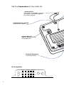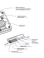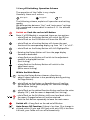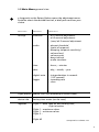
1
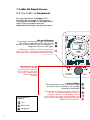
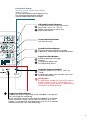
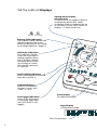
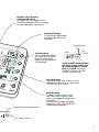
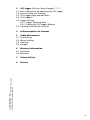
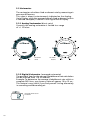
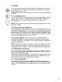
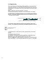
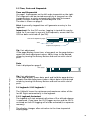
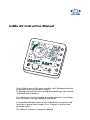
CoMo AV Instruction Manual
Your CoMo is one of the most versatile, well featured and easy
to operate flight instrument systems.
To provide you with the most straightforward access, the manual
is divided into 8 chapters.
For rapid access the first chapter gives the important instructions:
keys, functions, settings, displays and menus.
A more detailed description of the individual instructions and
functions is given from chapter 2 on. Chapter 3 outlines the
software status.
The table of contents is found on page 9.
1 CoMo AV Rapid Access
1.1 The CoMo AV Keyboard
For easy operation the Keys (PushButtons) are arranged in two groups:
The Function Group is on the right hand
side of the instrument and the
Adjustment Group is along the bottom.
The on | off-Button
in contrast to most other flight instruments
the CoMo is equipped with a real on | offButton. A short push will turn the CoMo on. A
long push will turn it off again.
In adjustment mode this button assumes the
"exit" function. False inputs may be reset by a
short push. Push repeatedly to leave the menu.
Adjustment Group
Adjustments can be
performed by the keys
in this section. They will
be mainly used before
take-off or after
landing.
Rotary-Button
Push the Button to shift into next Flight
profile (if active). Rotation turns pages
forward or backward.
Explanation of
symbols:
turn
brief push
long push
1
A long push on the button opens the menu
of the instrument. Rotation selects a
function, which is confirmed by a brief
push. Within the menu any adjustment can
be executed. The page-display will provide
additional information.
Functional Group
The keys in this section offer direct
access in flight.
All Function buttons are located next to
the corresponding display, making
incorrect operation most unlikely.
Altitude-Function-Button
A brief push shifts to the next value
(e.g. from "alt 1" to "alt 2").
Make a long push to enter the
adjustment menu.
Track-Function-Button
(no function yet)
Speed-Function-Button
Switches between different speedindications, according to connected sensors.
Page-Function-Button
Switches between all page
displays.
A long push opens the
corresponding menu.
Acoustic-Function-Button
Acoustic can be set to "off", "soft" or
"loud".
A long push opens the acoustic menu for
further adjustment.
CLR-Button
In adjustment mode the Acoustic-FunctionButton converts into a Clear-Button, by
which a value can be set to "0" directly (e.g.
altitude of landing ground).
Logger-Function-Button
This button allows flight data to be recorded. A long push
will start/stop the recording.
In the standard version your personal logbook is activated
(date, max/min values), and in the OLC version the "OLCLogger" is activated. (A change of more than 15 m in altitude
will automatically start the recording).
2
1.2 The CoMo AV Displays
Analog-Vario-Display
(direct-vario)
The position of the needle is quickly
and precisely discernible. Shows
immediate climb- or descend-rate up
to 10 m/sec (current value shown on
display: 1,7 m/sec climb-rate)
Bat. full
Bat. empty
Battery-State-Indication
The number of dots indicates the
remaining battery life (more
details on battery-life are found
on the Page-Indication "page 2")
GPS-State-Indication
This indication flashes
when the instrument is
seeking satellites. When
ever a satellite is found,
one more dot will light
up. All dots on means
that the GPS receives 612 satellites.
Profile-State-Indication
Shows which profile is activated
(one dot = profile 1).
Audio-Indication
Shows if the acoustic
function is set to "soft",
"loud" or "off".
OLC-Logger-Indication
shows if the instrument
is recording flight data
(only with built-in OLC
logger)
Piezo Beeper
for audio variometer.
Page-Display
in adjustment mode:
hints for operation
3
Digital-Vario-Display
(integrated-vario)
This gives the averaged rate of
climb (the timespan for the average
can be adjusted in the menu).
Altitude-Display
3 individually adjustable
altitude-indications are
available.
flight direction
Track-Display
Gives information about
the track (only in combination with a GPS,
otherwise temperature
is displayed).
Track
north
Track and the north-pointer
are only shown when the
instrument moves faster
than 1,5 km/h (the GPS is
unable to identify a track
without movement!).
Speed-Display
In combination with a GPS the SOG
(Speed Over Ground) can be shown
– enhancing your safety.
directional / functional hints
Page-Display
Displays further information
like time, date, battery-state
(up to nine pages according to
software).
In adjustment-mode the pageindication turns into a built-in
instruction-manual.
Menu-Level
4
1.3 The Connectors of the CoMo AV
"Screw Driver"
The washer is intended to unscrew
and remove the mountingplate
for battery change.
Connection for Lanyard
to secure the CoMo
System Bus left
Add-On modules can be
connected here
External Connector
(see detail below)
Pin Assignment
beep 2
speed
RS232 TX
ground
ground
ground
USB
beep 1
5
RS232 RX
M4 threaded sleeve
for any kind of mounting. Make sure
that the threaded sleeve is screwed in
to the correct depth (max. 8 mm).
System Bus right
Add-On modules can be
connected here
Battery case
silicon cover
Pressure port
for dynamic
pressure
RS 232
connector
Pressure port
for static pressure
Speed sensor
impeller-sensor connection
external beeper
connection (especially for
motor pilots)
USB connector
mini usb connector (5 poles)
6
1.4 on |off Switching, Operation Schema
The operation of the CoMo is very simple.
Generally there are 3 actions:
brief push
long push
turn
The following schema, explains all operation and setting
modes.
We differentiate between "fast" and "main menu” settings.
This is explained in more detail in section 2.1.1. for altitude
adjustment.
Switch on: Push the red on /off-Button
Note: if a GPS Module is connected, there are two options:
- a brief Push on the Rotary-Button will switch the GPS on
- a brief Push on the CLR-Button will leave the GPS off
- a brief Push on a Function-Button will choose the next
function of the corresponding display, e.g. from "alt 1" to "alt 2".
- a brief Push on the Rotary-Button will shift flightprofiles.
- Rotating the Rotary-Button will turn the page display
forward or backward.
- a long Push on any Button will switch to the adjustment
mode of a displayed function.
(Fast Setting)
- a long Push on the Rotary-Button will switch to the
adjustment menu.
(Main menu Setting)
Within the Main Menu:
- turning the Rotary-Button chooses a function or
adjusts values (selection is also possible by briefly pushing
the Page Button).
- a brief Push on the Rotary- or Page-Button will confirm
the selection of the value (display ‘OK’ confirms storage)
(Main Menu Setting).
- a brief Push on the related Function-Button confirms the value
(display ‘OK’), and the menu is departed (Fast Setting).
- a brief Push on the Exit-Button shifts one level back within
the menu. Changed values will not be retained.
Push the Exit-Button repeatedly to leave the main menu.
Switch off: A long Push on the red on/off-Button
auto
7
Auto-Power-Off Function: If there is less than 15 m change in
altitude within 15 min and SOG (only with activ GPS) is less than
4.4 km/h, your CoMo will turn off automatically.
1.5 Main Menu general view
a long push on the Rotary-Button opens the adjustment-menu.
Rotation selects the desired function, a brief push confirms your
choice.
Menu-level 0
Menu-level 1
Menu-level 2
settings
altimeter
– alt 1 manual adjustment
– alt 2 manual adjustment
– (zero) alt 3 manual adjustment
audio
– descent threshold
(point of response)
– damping (response-sensitivity)
– volume loud
– volume quiet
– beep interval
– audio simulator
time
– hours, – minutes
date
– day, – month, – year
digital-vario
– integrationtime in seconds
(1-32 seconds)
– recording rate
– clear
logger
flight profile
profile 2 on | off (according to current state)
device info
battery time meter (can be reset)
logbook
Flight 1 – date, take off and landing time,
flight duration
Flight 1 – maximum values
Flight 1 – minimum values
Flight 2 ...
...
Flight 63
corresponds to software 1.27
8
Table of Contents
1
1.1
1.2
1.3
1.4
1.5
CoMo AV Rapid Access
The CoMo AV Keyboard
The CoMo AV Displays
The Connectors of the CoMo AV
on /off Switching, Operation Schema
Main Menu general view
2 Description of the Functions
2.1 Altimeter
2.1.1 Altitude adjustment
"Fast Setting"
"Main Menu Setting"
2.2 Variometer
2.2.1 Analog Variometer (direct vario)
2.2.2 Digital Variometer (averaged variometer)
2.3 Audio
2.3.1 Volume Levels
2.3.2 Descent-Tone Threshold
2.3.3 Time Interval (interval between 2 climbing beeps)
2.3.4 Response-Sensitivity
2.3.5 Audio Simulator
2.4 Flight Profile
2.5 Time, Date and Stopwatch
2.6 Logbook
2.6.1 Logbook Autostart
2.6.2 Logbook Manual Start
2.7 Battery Condition
2.7.1 Battery Replacement
2.8 GPS * ***
2.8.1 Cold-Start
2.8.2 Warm-Start
2.8.3 Satellite-State-Indication
2.8.4 Indication of Position and Altitude
2.8.5 Track and Northpointer
2.8.6 SOG (Speed over Ground) and Windanalysis
2.8.7 Glide Ratio over Ground (l/d ratio)
9
3
3.1
3.2
3.3
3.4
3.5
OLC-logger (OnLine Contest-Logger) ** ***
Basic Information for operating the OLC-logger
Start and Stop of a Tracklog
OLC-Logger Page and Indication
OLC-Logbook
Logger Settings
3.5.1 Logger Sampling Rate
3.5.2 Erasing the OLC-Logger Memory
3.6 Tracklog Data Transfer to the PC
4
Softwareupdate via Internet
5
5.1
5.2
5.3
5.4
CoMo Maintenance
Overheating
Water Landing
Cleaning
Storage
6 Warranty Information
6.1 Disclaimer
6.2 Warranty
Technical Data
8
Release
* only with Add-On "…GPS"
** only with Add-On "…GPS" and Add-On "OLC-Logger"
*** Add-Ons have to be bought seperatly
7
10
2. Description of the Functions
2.1 Altimeter
Briefly push Altitude-Function-Button to shift between three
different altitude-indications.
"alt 1" and "alt 2" can be individually adjusted. The third altitude
"zero" sets the indication to 0, whenever this function is activated.
"alt 2" is linked to QNH (air pressure). If you are within the alt
2 adjustment menu, the speed indication shows the QNH value
corresponding to altitude. You may now adjust the altitude value
to the current QNH.
"zero"-function can be useful if you are flying in weak thermal
conditions over a longer period of time and want to be informed
about altitude gain or loss at one glance! (From software 1.32 on)
2.1.1 Altitude Adjustment
Altitude values may be changed in either "Fast Setting" (3 steps)
or "Main Menu Setting" (7 steps, but more options are available).
"Fast Setting"
- Push and hold the Altitude-Function-Button while the indication
shows the altitude value you wish to adjust. The instrument
automatically opens the adjustment menu.
- Adjust to desired altitude value by turning the Rotary-Button,
or set to zero by brief push on the CLR-Button.
- Confirm value by brief push on the Altitude-Function-Button.
The new value is confirmed by indication "o.k." and adjustment
menu is closed.
"Fast Setting" of "alt 2"
(Display shown after step 1.)
Display Altitude alt 2
1.
open adjustment-menu
3.
confirm
(back to standard
indication)
Menu indication on alt 2
QNH in mbar
leave menu without
storing changed values
(push repeatedly if
necessary).
2b.
2a.
11
set to desired value
set to zero
- Push the EXIT-Button repeatedly to leave the adjustment menu
without changes.
Hint: In case you want to change more altitude values, confirm
input by pushing the Rotary-Button instead of the AltitudeFunction-Button. This way you keep the adjustment menu active
for further adjustments.
"Main Menu Setting"
Altitude values may also be adjusted within the main menu:
Push and hold the Rotary-Button to enter the main menu. The
display reads "settings". Push Rotary-Button to select "altitude".
Push again to enter the altitude adjustment menu. Any available
adjustment functions display by turning the Rotary-Button. Press
the Rotary-Button to confirm the value you like to change. Set
altitude to desired value by rotating the Rotary-Button and
confirm with a brief push. The display will read "o.k.".
Push the Exit-Button repeatedly to leave the adjustment menu
(Before confirming values you may leave the menu without
storing any changed values by pushing the Exit-Button repeatedly).
"Main Menu Setting" of "alt 2"
(Display shown after step 5.)
Display Altitude alt 2
Menu indication on alt 2
QNH in mbar
leave menu without
storing changed values
(push repeatedly if
necessary).
5b.
1.
open Main-Menu
2.
select "settings"
3.
4.
set to zero
select "altimeter"
select desired function "alt 2"
5a.
adjust
6.
confirm
7.
leave menu by pushing the Exit-Button (3 times)
12
2.2 Variometer
The variometer calculates climb or descent rate by measuring air
pressure differences.
This value is almost instantaneously indicated on the AnalogVario-Display, while the averaged rate of climb or descent (within
a selected timespan) is shown in the Digital-Vario-Display.
2.2.1 Analog Variometer (direct vario)
Currently the analog variometer is limited to a range
of +/- 10 m/sec.
800 ft/min
climb
150 ft/min
descent
2.2.2 Digital Variometer (averaged variometer)
The period of time for the average climb/descend rate calculation
can be selected from 1 to 32 seconds.
Example: To determine the average climb/descent rate within a
complete 360° turn, you choose a value of approx. 10 to 15 sec..
This feature is very useful if you find yourself circling alternately
in ascending and descending air.
averaged climb rate of
120 ft/min
13
2.3 Audio
loud
quiet
off
The volume can be quickly adjusted in flight by the AcousticFunction-Button. A brief push shifts from "loud" to "quiet"
and further on to "off".
The present state of the acoustic is shown in the corresponding
display.
2.3.1 Volume levels
"loud" and "quiet" volume each have 6 programmable volume
levels: Adjust "quiet" volume (respectively "loud" volume) in
the main menu to your personal taste on a scale from
"1" to "6".
Hint: Hold Acoustic-Function-Button pushed to enter the "Fast
Setting" mode.
2.3.2 Descent-Tone Threshold
The threshold of the descent-tone can be adjusted within the
adjustment menu from "0" to "9.9" m/s, according to personal
taste. E.g.: If adjusted to 1,5 m/s the sound sets in beyond a
descent-rate of 1,5 m/s while it remains quiet between 0 and
1,5 m/s. Most pilots prefer a set-up between 3 and 4 m/s, more
than the average descent-rate in turns.
2.3.3 Time Interval (interval between 2 climbing beeps)
Some pilots prefer in weak thermal conditions really wide
intervals between the beeps, while others prefer a perpetual
acoustic indication.
Hint: Set profile 1 and 2 to identical acoustic modes, but the
first profile with wide (1) the other with short (9) intervals.
Change profiles in flight to find out your personal preference.
2.3.4 Response-Sensitivity
This is the most important audio adjustment option. Usually
you do not want your variometer to react too sensitively to
brief, narrow bands of lift.
A practical value will be about 1 sec delay. This means that if you
are flying at 36 km/h the thermal must have a diameter of at
least 10 m in order to activate the lift audio!
2.3.5 Audio Simulator
The audio simulator gives an expression of your variometer
acoustic during flight (acoustic on). Turn the Rotary-Button and
listen in on the beeptone corresponding to the climbrate (up to
10 m/s).
14
2.4 Flight Profile
The new feature of freely adjustable profiles is very useful for
varying flying tasks. For any demand (thermalling, cross-country,
acro) there is a configuration you can pre-adjust and recall when
needed.
Hint: In delivery-state only profile 1 is active!
To use further profiles, they have to be activated in the menu.
By a brief push on the Rotary-Button you can shift between different
profiles. The page-indication briefly shows which profile is active
– for about one second.
temporary info
appears for 1 sec. after profile has been changed
The profile-state-indication permanently displays the active
profile. The number of visible dots corresponds to profile-number
profile-state-indication
profile 2 active
All adjustments in the menu can be stored within the actual
profile.
Example for practical use:
Set profile 1 for normal thermal conditions to descend-tonethreshold 3 m/s and response-sensitivity to 1,0 sec.
When struggling in weak thermals set profile 2 so that the sinktone-threshold is 1.5 m/s and the response-sensitivity is 1.2 seconds.
15
2.5 Time, Date and Stopwatch
Time and Stopwatch
On page 1 time appears on the left and a stopwatch on the right.
The stopwatch can be started manually by a long push on the
Logger-Button, or starts automatically when the instrument
passes through a change in altitude beyond 15 m.
The date is shown on page 3.
Hint: A manually stopped time will generate an entry in the
logbook!
Important: On the OLC version, logging is started this way by
hand. So if you want to use only the stopwatch, ensure that the
GPS has been switched off (see 2.8).
time and stopwatch page
time
stopwatch (logbook)
Tip: Fast-adjustment
If the page display shows time, a long push on the page button
opens the time-adjustment-menu. Adjust time to the desired
values by turning the Rotary-Button and confirm with a brief
push.
Date
Date is displayed on page 3.
** only with Add-On "…GPS" and Add-On "OLC-Logger"
date page
Tip: Fast-adjustment
If the page-display shows date, push and hold the page-button
to open the date-adjustment-menu. Adjust date to the desired
values by turning the Rotary-Button and confirm with a brief
push.
2.6 Logbook / OLC-Logbook**
The CoMoAV stores the minimum and maximum values of the
last 63 flights automatically in the logbook.
2.6.1 Logbook Autostart
The logbook will start automatically when a 15 m altitude change
is measured. If you have the OLC-Logger version and the GPS is
switched on then 3D logging will also be activated (in a separate
memory).
The displays changes after activation to the time-stopwatch
display page.
16
2.6.2 Logbook Manual Start
The logbook can also be started manually by a long push on the
Logger-Button. The indication skips automatically to the
time/stopwatch-page and the stopwatch starts running.
time and flight duration
Stopwatch running,
flight will be recorded
Logbook Evaluation
The Logbook is accessible through the menu (long push on the
Rotary-Button, then turn until the display reads "Logbook"). A
brief push on the Rotary-Button will open "flight 1" (latest flight).
Three pages are shown for each flight.
The first page of the logbook gives basic information:
- Flightnumber, - Date
- Takeoff- and Landing-time, - Flight duration in hours and minutes
- Takeoff altitude (in Altitude-indication)
Turning the Rotary-Button clockwise leads to maximum values:
- max. climb rate (Analog-Vario), - max. averaged climbgrate
(Digital-Vario), - max. Altitude, - max. Temperature,
- max. SOG (only in combination with a GPS Module)
Another clockwise turn leads to minimum values:
- min. climb rate (Analog-Vario), - min. averaged climbrate
(Digital-Vario), - min. Altitude, - min. Temperature
The next clockwise turn leads to flight 2, page1, ... etc.
17
2.7 Battery Condition
The CoMo AV uses two AA-cells. The battery-state-indication and
battery-info-page keeps you informed about the battery condition.
The battery-info-page shows on the left the actual voltage. New
cells should provide at least 3.2 V. If voltage falls short of 2.2 V,
cells should be changed.
Next to it is a meter for operating-hours. The percentageindication converts the voltage into an easily understandable
percent-value.
Battery info Page
Voltage
remaining
power in %
battery time counter
Any kind of battery state indication will be affected in cold
conditions when battery cells and accumulators suffer a
considerable loss of capacity.
E.g. a pilot may take off at 20 °C with the instrument indicating
a capacity of 40 % only to find it soon afterwards reduced to 5
% at a temperature of -10 °C at 4000 m MSL...
Apart from competition flying, Alkali-Mg cells should work very
well. To ensure satisfactory operation in low temperature
environment (winter flying or high altitudes) 1,5 V Lithium cells
can be used as well (www.energizer-eu.com). Our Solar-Module
represents the ultimate solution (appearing summer 2008).
If voltage drops below 2.2 V, the GPS is turned off, but the audiovario-function is maintained. In this case it is high time to change
batteries.
18
2.7.1 Battery Replacement
Remove the mounting-plate on the rear of the instrument.
Beneath, the cell compartment is covered by a silicon cap. Remove
the cap cautiously and put in new cells. Never mix different kinds
of cells and make sure you load the compartment properly (+/are marked inside).
You can estimate the remaining operation-time by watching the
battery-time-counter. A new set of batteries should be good for
about 700 h airtime without GPS (CoMo AV + easy GPS approx.
140 h airtime).
Important: Make sure you load the compartment properly.
Hint: Use the washer on the safety cord as a screw driver to
remove the mounting plate.
Remove silicon cap cautiously by the flap.
+ Pole
Remove empty batteries one at a time,
plus pole first.
Put in new batteries one at a
time, plus pole first.
Important:
Reset the battery time counter after replacing the batteries.
19
2.8 GPS*
After switching on the CoMo AV (with Add-On GPS) you are
asked if you intend to switch the GPS on or off.
first page
on all GPS models
Activate the GPS by a brief push on the Rotary-Button. The
pageline reads:
GPS Page
When the GPS has found 4 satellites, the present position is
indicated:
GPS Page
If the GPS is not needed, push the CLR-button. When you call up
the GPS-page, it reads:
GPS Page
Hint: A long push on the Page-Button (while GPS page is displayed)
will get you into the GPS on/off switching menu.
Important Note: The GPS Module must not be covered, as this
could spoil the reception. The fewer the obstacles (trees, buildings,
rocks etc.) the better it will perform. Indoors it will not work at
all.
We distinguish between "Cold-Start" and "Warm-Start".
*
only with Add-On "…GPS"
2.8.1 Cold-Start
After changing the batteries, or after having moved to another
location, the GPS cannot refer to stored information. This can
delay the location of your position by as much as 15 minutes.
2.8.2 Warm-Start
If the GPS is activated at the same spot as it was last turned off
it can quickly find its position again (1-3 minutes) using stored
data.
Hint: Turn on your GPS as soon as you arrive at the take off area,
to give it maximum time for orientation. When a position is
identified, turn the GPS off and you are ready for a quick "WarmStart" when you actually begin your flight.
20
2.8.3 Satellite-State-Indication
This indication keeps you informed about GPS-reception. If the
core of the indication flashes, the GPS is in search-mode. For
every satellite found, one dot lights up. Although your GPS is
capable of receiving up to 16 satellites, the indication only shows
up to 6. More than six satellites are not necessary.
flashing core = search for satellites
- no position displayed
one more dot for each satellite found.
4 satellites found, flashing stops.
- sufficient reception for position analysis
6 -12 satellites found
- perfect reception
2.8.4 Position and Altitude Display (page 5)
Position is shown in degrees of longitude and latitude. The GPS
uses the world cup standard format WGS 84
(degreedegree,decimaldecimaldecimaldecimaldecimal) to display
the position.
GPS Page
GPS-altitude
Position
There is no indication in minute- or second-format yet.
Knowing your position in degrees of longitude and latitude is
useful when you have to guide people in case of emergency, or
just to bring you back after a cross country flight.
For technical reasons altitude determination by GPS is less precise
than the analysis of the geographic position. GPS-altitude is
shown with a significant delay after the position is found. At
first, values are rather inaccurate (aberrations of up to 50 m!).
After a while of operation the GPS-altitude becomes more exact.
Warning: Given the lack of accuracy of the GPS altitude reading,
regard it as only an approximate value when adjusting the
barometric altimeter.
21
2.8.5 Track and Northpointer
To define a track the GPS has to be moved horizontally by a
speed of at least 1.5 km/h whether you are flying or walking.
Remember: This is not as responsive as a magnetic compass!
flight-direction
track
north
indication only from 1,5 km/h on!
2.8.6 SOG (Speed over Ground) and Windanalysis
When GPS has found a position, the speed display shows speed
over ground (SOG). As SOG is a horizontal movement only, climb
and descend-rates have no influence at all on its value. The SOGdisplay lets you judge the wind situation, as it is a compound of
air-speed and wind-speed. Flying with tail-wind adds values,
while flying with head-wind subtracts wind-speed from air-speed.
Example: if the SOG is 60 km/h in one direction and in the
opposite direction only 20 km/h, then you travel at 40 km/h
while wind velocity is 20 km/h.
Warning: Never try to judge wind-direction close to ground just
by watching your SOG! Valley winds, thermals etc., may totally
alter the wind direction and speed in a chosen landing area.
Better to rely on the good old trusty windsock or natural indicators
(smoke, a rustle in a cornfield, ripples on a lake´s surface, etc.)!
22
2.8.7 Glide Ratio over Ground (l/d ratio)
The glide ratio over ground is the ratio between your speed over
ground (delivered by the GPS module) and the digital vario value.
Example: Flying at 36 km/h (10 m/s) while descending at 1 m/s
means your glide ratio over ground is 10.
Important: The longer the timespan setting of the digital vario,
the smoother is the display.
Glide ratio page
Hint: on cross country flights this feature will help you to save
altitude on long, straight passages (e.g. while crossing a valley):
Always aim for the airspeed that provides maximum glide ratio
over ground.
Knowing your glide ratio over ground can also help you to judge
wind direction and wind speed.
If there is no data available, or when you are climbing, the display
will read 99.9.
3 OLC-Logger (OnLine Contest-Logger)**
Important: The CoMo records the position from the GPS and
the barometrical altitude "alt 2". Make sure "alt 2" is correctly
set. The CoMo does not record the GPS altitude (see also 2.8.4).
"alt 2" must be set to the correct
takeoff altitude e.g. 1453 ft
3.2 Start and Stop of a Tracklog
The OLC-Logger is started manually by a long push on the LoggerButton (make sure your GPS is on, otherwise only the logbook
is started). The display switches automatically to the
time/stopwatch page, and the recording begins (stopwatch starts
running). The OLC-Logger has the same autostart function as
the logbook (see 2.6.1). The log is terminated by a long push on
the Logger-Button, or simply by switching off your CoMo.
23
** only with Add-On "…GPS" and Add-On "OLC-Logger".
3.1 Basic Information for operating the OLC-Logger
You can record the 3-dimensional position of your flight with
the OLC-logger. This is an indispensable feature for the Online
Contest participation and for any graphical representation of
your flight in programs like Google Earth et al..
3.3 OLC-Logger Page and Indication
OLC logger page:
The page shows the current state and settings (on, off, number
of logged points, recording interval, Log number and remaining
logging capacity in hours).
OLC-Logger Page
record interval in seconds
number of tracklogs
remaining record time
number of logged points
OLC-Logger Indication:
Logger activity is permanently indicated even while you are using
other pages than the Logger page or the time/stopwatch page:
OLC-Logger Indication
If dots are rotating the logger
is recording properly.
If all dots are flashing,
GPS data are insufficient.
3.4 Logbook
On the OLC version the tracklogs are marked as "log" instead
of "flight" in the logbook (see 2.6 logbook).
3.5 Logger Settings
3.5.1 Logger Sampling Rate
A capacity of 65535 tracklog points is available. Depending on
the interval between tracklogs your recording time can be up to
558 hours (recording interval set to the maximum of 31 sec.).
As a rule of thumb there are 18 hours capacity with a log sampling
rate of once per second.
We recommend an interval of 3 and 6 seconds between each
log (giving 54 to 108 hours recording time). The resolution is
good enough to display individual 360s, and to provide accurate
graphics of thermals, etc.
The intervals between tracklogs can be set under: logger, set
logger sampling rate, … .
Loggermenu Display
24
3.5.2 Erasing the OLC-Logger Memory
The memory of the OLC-Logger will be erased completely in only
one step (flash memory). Ensure that all important flights have
been transferred to the PC before erasing the memory. The
function "erase memory" is in the menu: "settings"–"logger".
Tip: We recommend that you erase the memory immediately
after transferring data to the PC. If you experience problems
during the transfer, or if you have performed an update, erasing
the memory will re-initialise the file system.
The memory erase is started by a
long push on the clr-Button.
Important: After a software update or a software hang the OLC
memory must be erased to ensure proper operation.
3.6 Tracklog Data Transfer to the PC
To transfer the data to the PC you need to have the correct USB
driver on your PC. On most PCs this is already there, because we
use a very popular FTDI chip, which is supported by most operating
systems (see also 4.a).
a) Connect the CoMo via the USB cable to your PC
b) The PC assigns a virtual COM-port to your CoMo (see also 4.f)
c) Enter the logbook at your CoMo using the Rotary-Button until
"log 01 to pc, press rotary for transfer" appears
Logbook Display
Push the Rotary-Button to switch to transfer mode. The Display
reads:
Logbook Display
d) Start your OLC upload program like Maxpunkte, CompeGPS
or SeeYou at the pc.
Hint: All programs supporting the MLR format can be used, e.g.
Kashmir in Japan. There are demo versions of the most popular
programs on our CD.
Hint for MaxPunkte user: At the first upload attempt a window
with the message "no argument for %d"might open. Initialise
Maxpunkte with the correct COM-Port setting and after restart
of the program this error message will not appear any more.
If you use several CoMos at the same PC, they will all get a unique
COM-Port number. So this has to be set up for every CoMo used.
25
Important: The Maxpunkte program only supports Com-Port
numbers up to 9. If your PC assigns a higher number to the CoMo,
then you have to use the device manager menu of Windows to
select manually a Com-Port number below 9.
Tracklogs can only be transferred one at a time.
4 Softwareupdate via Internet
You will find on our webpage www.renschler.de under support
and download the latest version of the CoMo software.
Compare the software revision number (see under menu and
device information) of your CoMo with the version number in
the internet.
If the internet number is higher, you can do an update via internet
(USB interface required).
The following steps are necessary for an update:
Important: To avoid software damage never perform an update
when the batteries are weak. Should they fail during the update
you will have to return your CoMo to the factory for repair!
a) The CoMo must be detected by your PC, otherwise you have
to get the USB driver from www.ftdichip.com.
b) You need to download our flashloader program from our
website or use the one delivered with your CoMo CD.
c) Download the update software to your PC.
d) Install the flashloader by double clicking the file
"flashloader.exe".
e) Connect the CoMo via USB to your PC
f) Turn on the CoMO into the special software update mode by
pressing simultaneously the on key plus the clr and alt key.
"start software update at the pc" appears in the page display.
26
g) Start the Flash-Loader program and follow the instructions
on the PC screen:
Hint: Run the Flash-Loader once without connecting the CoMo
and memorise the serial ports shown in the box. Then connect
the CoMo and restart the program. Your CoMo connects to the
port which is now shown in the box!
select Com-Port
"upload" opens the selection screen.
Choose the new software-file "... .hex".
h) After the update has finished, (sometimes with a stop) first
remove the USB cable and then switch the CoMo off.
After a successful upload the program closes automatically.
27
5 CoMo Maintenance
5.1 Overheating
Never expose your CoMo to extreme temperature, e.g. behind
the windscreen of the car (greenhouse effect). Overheating may
cause severe damage.
5.2 Water Landing
After a water landing especially in salt water batteries should
be removed immediately. Open the housing (4 screws on the
rear), rinse all PC-boards carefully with clean water and dry them
thoroughly afterwards.
Important: If the CoMo doesn't work after this procedure,
remove the batteries at once to avoid further damage!
In this case you have to send your CoMo in for repair (without
batteries!!!).
5.3 Cleaning
Use a wet cloth for cleaning. No aggressive cleaners.
5.4 Storage
If you are not using your CoMo for a longer period of time, then
remove the batteries and store it in a cool, dry place.
6 Warranty Information
6.1 Disclaimer
Electronic or mechanical failures may cause false readings, eg:
pressure transducer damage may result in incorrect altitude
values! Renschler is not liable for any damage or injury caused
by a faulty instrument – the pilot is solely responsible for safety
in flight.
6.2 Warranty
We issue a guarantee of 2 years on material and processing
defects.
Electronic or mechanical damage after a crash or waterlanding
is not covered.
28
7 Technical Data
. up to 9000 m NN (0 to 29.999 ft), resolution 0,3 m (1 ft)
display in m and/ or ft1
. adjustable from - 4000 to 9000 m (-12.000 to 29.999 ft)
Alt 1
. adjustable with QNH
Alt 2
. displays QNH, or zero-altimeter
QNH / Zero 1
(zeroes altimeter when activation)
. analog: high resolution 360 degree display incorporating
variometer
the integrated vario display
. from -20 to +20 m/s, in 0,16 m/s steps
Analog
. from -45 to +45 m/s, in 0,1 m/s steps
Integral
integration time . adjustable between 1 and 31 sec, in 1 sec steps
. frequency and interval modulated for climbing
audio
frequency modulated sink tone
–
. 3 volume levels: Level 1: "low",
audio volume
Level 2: "high", both levels are individually
adjustable in 6 steps. Level 3: "audio off".
. adjustable between 0,1 and 9,9 sec, in 0,1 sec steps
damping
descent threshold . adjustable between 0 m/s and -20 m/s, in 0,2 m steps
. in 24 hours mode
date, realtime
. stopwatch up to max. 99 h and 99 min, resolution: 1 sec
stopwatch
. impeller-sensor (several design),
airspeed1
range: 0 to 140 km/h
. in air (when optional sensor fitted)1, over ground*1,
glide ratio
to landing place*1, display from 0 to +/- 99,9, in 0,1 steps
. G-force measurement up to max. 10 g with
g-meter***1
0,1 g resolution (3-D xyz data)
. memory for all min. und max. values of:
logbook
altitude, variometer, speed, temperature, date,
take off and landing time, start position*1,
landing position*1, g-force***1
. 8 MB-Flash memory, 65535 3D tracklog points,
OLC-Logger**
recording time adjustable from 2 to 31 sec.
2 sec = 36 hours, 31 sec = 558 hours
micro card slot 1 . micro card slot for memory expansion.
(control zones)
. 2 AA batteries. Consumption around 2-4 mA, which
power system
and consumption corresponds to 700 to 1400 hours of operation.
(140 hours operation time with Add-On "easyGPS").
If Add-On "solarGPS" is connected the batteries are
only used for the clock function and
during "night operation".
. polycarbonate housing, CoMo AV: 80 x 80 x 24 mm
dimensions
(29,5 mm incl. Rotary-Switch), 150 g incl. batteries
included in delivery . instrument, pocket, mini usb cable,
CD with div. software, owners manual.
. various mountings, ASI sensors,
options
PC-software, GPS-cable1
. modular system expandable to suit your needs,
updates
flash-update via internet
. 24 months
warranty
29
* only with Add-On "…GPS"
** only with Add-On "…GPS" and Add-On "OLC-Logger"
*** only with Add-On "G"
1
not jet available
altimeter
8. Release
1.27 remarks:
After 14 months of LCD-Dispaly development plus another 15
months designing new hard- and software we take a lot of pride
in our new CoMo AV, as it sets completely new standards in some
domains.
- extremely sensitive variometer (definite measurement of
climbing rates from 5 cm/sec on).
- fabulous 700 h of battery life (without GPS)
- even with GPS the instrument endures an operation
time of 140 h.
- operation is nearly fool-proof with the solid Rotary-Button
- "FOCUS Energy" award for excellence in industrial design
There are still some limitations in release 1.27:
- analog variometer can only display values up to +/- 10 m/sec.
- vario and altimeter indication only in meters
- no temperature indication when easy-GPS-Module is employed
- no "zero-click" acoustic when altitude level remains
the same over a longer period of time
- no support for altitude "Zero | QNH"
- no support for airspeed-sensors
Next steps in software development:
Navigation: - distance to waypoint
- bearing to waypoint
- glide ratio to waypoint
Release 2.0 is scheduled for 2008
the following products are in the design stage:
- solar- and solarGPS-Module
- G-Meter (G-Force measurement for Acro-Pilots)
- PWC-Contest version
We will keep you informed on our web site: www.renschler.de
about updates and accessories.
Don´t hesitate to give us your opinions and suggestions on the
CoMo. Mail to: [email protected]
Have a lot of nice flights with your CoMo.
Enjoy. Be a CoMo sapiens!
Your Renschler Team
30
Grafik: Bachmayer, Stuttgart 2008
Ingenieurbüro Renschler,
Tel.: + 49 (0) 711- 879 462, FAX: + 49 (0) 711- 870 11 80,
Kirchtalstr. 30, D -70435 Stuttgart, Germany, www.renschler.de
errors, ommisions, tech. changes,
delivery & prices excepted
20.05.08
instruction manual eng. rev. 1.5