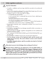
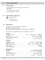
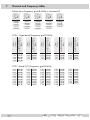
1
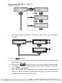
Head-End Digital Modulator COFDM / QAM HDMT 1000 ASI LAN KLASSE HDMT 1001 C English CLASS GSS Grundig SAT Systems GmbH Beuthener Strasse 43 D-90471 Nuremberg Phone: Fax: E-mail: Internet: +49 (0) 911 / 703 8877 +49 (0) 911 / 703 9210 [email protected] http://www.gss.de Contents 1 Safety regulations and notes .....................................................................................4 2 General information .................................................................................................5 2.1 Packing contents ..........................................................................................5 2.2 Meaning of the symbols used ........................................................................5 2.3 Technical data .............................................................................................5 2.4 Description .................................................................................................6 2.4.1 Input signal path “INROUTE” ..............................................................6 Menu setting “A+ASI = 1 B+ASI = 2” ................................................6 Menu setting “A+B+ASI = 1 ASI = 2” ................................................7 Menu setting “A+ASI = 1 A+ASI = 2” ...............................................7 2.4.2 Output signal path “OUTROUTE” ........................................................7 Menu setting “ASI => ASI” .................................................................7 Menu setting “1 => ASI ASI => MA” .................................................8 Menu setting “2 => ASI ASI => MB” .................................................8 2.4.3 General ...........................................................................................8 2.5 Software query............................................................................................9 2.6 How the TPS module works ...........................................................................9 3 Assembly ...............................................................................................................11 3.1 Installing the cassette..................................................................................11 3.2 EMC regulations ........................................................................................11 3.3 Overview of the cassette ............................................................................12 3.4 Connecting the cassette ..............................................................................13 3.5 Retrofitting a CA module ............................................................................13 4 The control panel at a glance ..................................................................................14 4.1 Menu items ...............................................................................................14 4.2 Control panel ............................................................................................14 5 Programming .........................................................................................................15 5.1 Preparation ...............................................................................................15 5.2 Programming procedure .............................................................................16 Channel strips “A” (without CA module) and “B” ...........................................16 Channel strip “A” with CA module ..............................................................19 5.3 Programming the cassette ..........................................................................20 Selecting the cassette .................................................................................20 Selecting the input signal path .....................................................................21 Selecting the output signal path ...................................................................21 Setting the ASI transfer rate .........................................................................22 Setting the ASI options ...............................................................................22 Selecting the channel strip ..........................................................................23 Selecting channel / frequency setting ...........................................................23 Setting the output channel ...........................................................................24 Setting the output frequency ........................................................................24 Switching the modulator off or on ................................................................24 Adjusting the output levels of the channel strips .............................................25 -2- HDMT 1000 ASI LAN / HDMT 1001 C Setting the input channel ............................................................................25 Setting the hierarchical modulation ..............................................................26 Setting the station filter ...............................................................................27 Setting the QAM modulation ........................................................................ 30 Inverting the user signal ..............................................................................31 Setting stuffing...........................................................................................31 Setting a substitute signal in the case of an incorrect input signal ....................32 Setting the transport stream ID and the ORGNET-ID .......................................33 Network Information Table (NIT) ..................................................................33 Setting the network/operator identification ...................................................34 Deleting a PID ...........................................................................................35 Renaming a PID.........................................................................................35 Factory reset .............................................................................................36 Saving settings ..........................................................................................36 5.3.1 Operation with a CA module ............................................................37 Setting the scrambling ......................................................................37 Setting the PID monitoring ................................................................38 Configuring the CA module ..............................................................38 Setting the station filter .....................................................................39 6 Final procedures .....................................................................................................41 7 Channel and frequency tables .................................................................................42 -3- HDMT 1000 ASI LAN / HDMT 1001 C 1 Safety regulations and notes Important information Ê Ê Ê Ê Ê Ê Ê Ê Ê Ê Ê Ê Ê Ê Ê UÊ ÃÃiLÞ]Ê ÃÌ>>ÌÊ >`Ê ÃiÀÛV}Ê Ã Õ`Ê LiÊ V>ÀÀi`Ê ÕÌÊ LÞÊ >ÕÌ ÀÃi`Ê iiVÌÀV>ð UÊ -ÜÌV ÊvvÊÌ iÊ«iÀ>Ì}ÊÛÌ>}iÊvÊÌ iÊÃÞÃÌiÊLivÀiÊLi}}ÊÜÌ Ê>ÃÃiLÞÊÀÊÃiÀÛViÊÜÀÊÀÊ«ÕÊÕÌÊÌ iÊ>ÃÊ«Õ}° UÊ ÃÌ>ÊÌ iÊÃÞÃÌiÊÃÊÌÊÜÊÌÊLiÊ>LiÊÌÊÛLÀ>Ìio Ê Ê>Ê`ÕÃÌvÀii]Ê`ÀÞÊiÛÀiÌ Ê ÊÊÃÕV Ê>Ê>iÀÊÌ >ÌÊÌÊÃÊ«ÀÌiVÌi`ÊvÀÊÃÌÕÀi]ÊvÕiÃ]Êë>à }ÊÜ>ÌiÀÊ>`Ê`>«iÃÃ Ê ÃiÜ iÀiÊ«ÀÌiVÌi`ÊvÀÊ`ÀiVÌÊÃÕ} Ì Ê ÌÊÜÌ ÊÌ iÊi`>ÌiÊÛVÌÞÊvÊ i>ÌÊÃÕÀViÃ Ê Ê>Ê>LiÌÊÌi«iÀ>ÌÕÀiÊvÊäÊc ÊÌʳxäÊc °ÊÊV>ÃiÊvÊÌ iÊvÀ>ÌÊvÊ V`iÃ>ÌÊÜ>ÌÊÕÌÊÌ iÊÃÞÃÌiÊÃÊV«iÌiÞÊ`Ài`° UÊ ÃÕÀiÊÌ >ÌÊÌ iÊ i>`i`ÊÃÌ>ÌÊÃÊ>`iµÕ>ÌiÞÊÛiÌ>Ìi`°ÊÊÌÊVÛiÀÊÌ iÊÛiÌ>ÌÊÃÌð UÊ iÜ>ÀiÊvÊà ÀÌÊVÀVÕÌÃÊ UÊ Ê>LÌÞÊÃÊ>VVi«Ìi`ÊvÀÊ>ÞÊ`>>}iÊV>ÕÃi`ÊLÞÊv>ÕÌÞÊViVÌÃÊÀÊ >««À«À>ÌiÊ >`}° UÊ "LÃiÀÛiÊÌ iÊÀiiÛ>ÌÊÃÌ>`>À`Ã]ÊÀi}Õ>ÌÃÊ>`Ê}Õ`iiÃÊÊÌ iÊÃÌ>>ÌÊ>`Ê «iÀ>ÌÊvÊ>Ìi>ÊÃÞÃÌið UÊ / iÊ ÃÌ>`>À`ÃÊ É É Ê ÊxäänÎÊ >`Ê É É Ê ÊÈäÇÓnÊ ÕÃÌÊ LiÊLÃiÀÛi`° UÊ ÊÌÊ«iÀvÀÊÃÌ>>ÌÊ>`ÊÃiÀÛViÊÜÀÊ`ÕÀ}ÊÌ Õ`iÀÃÌÀð UÊ Test the software versions of the head-end station and the cassette and update them if necessary. The current software versions can be found at ”www.gss.de”. UÊ For further information please read the assembly instructions for the headend station used. Take action to prevent static discharge when working on the device! Electronic devices should never be disposed of in the household rubbish. In accordance with directive 2002/96/EC of the European Parliament and the European Council from January 27, 2003 which addresses old electronic and electrical devices, such devices must be disposed of at a designated collection facility. At the end of its service life, please take your device to one of these public collection facilities for proper disposal. -4- HDMT 1000 ASI LAN / HDMT 1001 C 2 General information 2.1 Packing contents 1 2 1 1 2.2 cassette HDMT 1000 ASI LAN or HDMT 1001 C HF cables CD (assembly instructions) Brief assembly instructions Meaning of the symbols used Important note —> General note Ê UÊ *iÀvÀ}ÊÜÀà 2.3 Technical data Ê The deÛViÃÊiiÌÊÌ iÊvÜ}ÊEU directives: 2006/95/EC, 2004/108/EC / iÊ«À`ÕVÌÊvÕvÃÊÌ iÊ}Õ`iiÃÊ>`ÊÃÌ>`>À`ÃÊvÀÊ Ê>Li}° Unless otherwise noted all values are specified as “typical”. HF input ÀiµÕiVÞÊÀ>}i\Ê°°°°°°°°°°°°°°°°°°°°°°°°°°°°°°°°°°° £ÇÇ°xÊoÊÓÓÈ°x]Ê{Ç{ÊoÊnxnÊâ Input level:Ê°°°°°°°°°°°°°°°°°°°°°°°°°°°°°°°°°°°°°°°°°°°°°°°°°°°°°°°°°°°°°°°ÈäÊ`6ÊoÊnäÊ`6 «ÊÌ ÀÕ} ÊÕÌ«ÕÌÊ}>Ê°°°°°°°°°°°°°°°°°°°°°°°°°°°°°°°°°°°°°°°°°°°°°°°°°°°°°°äÊ`ÊoÊÎÊ` Symbol rateÊ°°°°°°°°°°°°°°°°°°°°°°°°°°°°°°°°°°°°°°°°°°°°°°°°°°°°°°°°°°°°°°° >VV°ÊÌÊ ÊÎääÇ{{ HF output ÀiµÕiVÞÊÀ>}i\Ê°°°°°°°°°°°°°°°°°°°°°°°°°°°°°°°°°°°°°°°°°°°°°°° {Ó°äÊâÊoÊnÈä°äÊâÊ Channels:Ê°°°°°°°°°°°°°°°°°°°°°°°°°°°°°°°°°°°°°°°°°°°°°°°°°°°°°°°°°°°°°°°°°°°°°°°°°°°°°-Ó£ÊoÊ È Types of modulation:Ê°°°°°°°°°°°°°°°°°°°°°°°°°°°°°°°°°°° +Ê{]Ê£È]ÊÎÓ]ÊÈ{]Ê£Ón]ÊÓxÈ Output level:Ê°°°°°°°°°°°°°°°°°°°°°°°°°°°°°°°°°°°°°°°°°°°°°°°°°°°°°°°°°°°°°°°°°°°°°°°°°°°°° 96 dBµV Output impedance:Ê°°°°°°°°°°°°°°°°°°°°°°°°°°°°°°°°°°°°°°°°°°°°°°°°°°°°°°°°°°°°°°°°°°°°°°°°° 75 ASI interfaces Standard:Ê°°°°°°°°°°°°°°°°°°°°°°°°°°°°°°°°°°°°°°°°°°°°°°°°°°°°°°°°°°°°°°°°°°°°° Ê ÊxäänÎ Format:Ê°°°°°°°°°°°°°°°°°°°°°°°°°°°°°°°°°°°°°°°°°°°°°°°°°°°°°°°°°°°°°°°°*Ê-"Ê Ê£În£n£ User data rate:Ê°°°°°°°°°°°°°°°°°°°°°°°°°°°°°°°°°°°°°°°°°°°°°°°°°°°°°°°°°°°°°°°°° ÓÊoÊäÊLÌÉà Level (input / output):Ê°°°°°°°°°°°°°°°°°°°°°°°°°°°°°°°°°°°°°°°°°°°°°°°°°°°°°°800 mV** ± 10% Return loss (input):Ê°°°°°°°°°°°°°°°°°°°°°°°°°°°°°°°°°°°°°°°°°°°°°°° Ê£ÇÊ`ÊxÊoÊÓÇäÊâ® -5- HDMT 1000 ASI LAN / HDMT 1001 C Connections HF inputs: ...........................................................................2 IEC sockets HF loop-through outputs:.......................................................2 IEC sockets HF output: ........................................................................... 1 IEC socket ASI input: .................................................................£Ê ÊÃViÌ]ÊÇxÊ ASI output: ................................................................£Ê ÊÃViÌ]ÊÇxÊ LAN: ................................................................................ 1 RJ-45 socket Connection strip (10-pin): ...................for supply voltages and control circuits RS-232 socket: ..................................... serial interface for software update Common Interface: ................................ several channels can be decoded. 2.4 Description Ê / iÊ `ÕLiÊ ÌÀ>Ã`Õ>ÌÀÊ V>ÃÃiÌÌiÊ ÃÊ >Ê VÛiÀÌiÀ]Ê Ü V Ê VÛiÀÌÃÊ COFDM modulated stations into two QAM modulated signals for feeding into a cable network. The cassette has two HFÊ«ÕÌÃ]ÊÌÜÊ«Ì ÀÕ} ÊÕÌ«ÕÌÃÊ>`ÊiÊÊ output. Additionally it is equipped with an ASI input and an ASI output (ASI – Asynchronous Serial Interface according to EN 50083-9). The transport stream fed via the ASI socket can be inserted into the transport streams of the receiving stages via the TPS module. The signal path is set in the menu items input signal path “INROUTE” and output signal path ”OUTROUTE”. 2.4.1 Input signal path “INROUTE” Menu setting “A+ASI = 1 B+ASI = 2” The transport streams of the receiving stage “TS A” and of the ASI input “TS ASI” generate the transport stream 1. The transport streams of the receiving stage “TS B” and of the ASI input “TS ASI” generate the transport stream 2. SAT input ”A“ Receiving stage "A" TS A CA module TPS Transport stream 1 TPS Transport stream 2 TS ASI ASI input SAT input ”B“ Receiving stage "B" TS B -6- HDMT 1000 ASI LAN / HDMT 1001 C Menu setting “A+B+ASI = 1 ASI = 2” The transport streams of the receiving stages “TS A” and “TS B” and of the ASI input “TS ASI” generate the transport stream 1. The “TS ASI” transport stream fed via the ASI input generates the transport stream 2. SAT input ”A“ Receiving stage "A" SAT input ”B“ Receiving stage "B" TS A CA module TS B TPS Transport stream 1 TS ASI Transport stream 2 ASI input Menu setting “A+ASI = 1 A+ASI = 2” The transport streams of the receiving stage “A” “TS A” and of the ASI input “TS ASI” are split into transport stream 1 and 2. Receiving stage “B” is not used. SAT input ”A“ Receiving stage "A" TS A CA module TPS Transport stream 1 TPS Transport stream 2 TS ASI ASI input 2.4.2 Output signal path “OUTROUTE” Menu setting “ASI => ASI” Transport stream 1 is made available via modulator “A»]ÊÌÀ>ëÀÌÊÃÌÀi>ÊÓÊÛ>Ê modulator “B” and the transport stream from the ASI input “TS ASI” via the ASI output. Modulator "A" Transport stream 1 Combiner Modulator "B" Transport stream 2 ASI input HF output TS ASI ASI output -7- HDMT 1000 ASI LAN / HDMT 1001 C Menu setting “1 => ASI Ê ASI => MA” /À>ëÀÌÊÃÌÀi>Ê£ÊÃÊ>`iÊ>Û>>LiÊÛ>ÊÌ iÊ-ÊÕÌ«ÕÌ]ÊÌÀ>ëÀÌÊÃÌÀi>ÊÓÊ via modulator “B” and the transport stream from the ASI input “TS ASI” via modulator “A” (MA). Transport stream 1 ASI input ASI output TS ASI Modulator "A" Combiner Transport stream 2 Menu setting “2 => ASI HF output Modulator "B" ASI => MB” Transport stream 1 is made available via modulator “A»]ÊÌÀ>ëÀÌÊÃÌÀi>ÊÓÊ via the ASI output and the transport stream from the ASI input “TS ASI” via modulator “B” (MB). Modulator "A" Transport stream 1 Combiner ASI input TS ASI HF output Modulator "B" Transport stream 2 ASI output 2.4.3 General The cassette is equipped with two channel strips (“A” and “B”). The channel ÃÌÀ«ÃÊVÃÃÌÊvÊÌ iÊ`}Ì>ÊÌiÀÀiÃÌÀ>ÊÌÕiÀÃ]ÊÌ iÊ`}Ì>ÊÃ}>Ê«Ài«>À>ÌÊÕÌÃÊ and the output converter. The channel strips are indicated in the head-end station display with “Bx …A” and “Bx …B”. Using an adequate CA module encoded channels can be decoded via channel strip “A”. In addition cassette HDMT 1001 C is able to scramble unscrambled channels via an adequate CA module. The control of the cassette takes place via the control unit of the headend station. Two LEDs provide an indication of the input signal quality based on their colour and indicate if the respective channel strip is switched on (LED illuminates) or off. The integrated TPS module (Transport Stream Processing) processes the data of the transport streams. -8- HDMT 1000 ASI LAN / HDMT 1001 C Ê 2.5 Ê Ê The QAM modulated HF output signals are sent through the HF output of the cassette to the HF output collector. The common output level of the channel strips can be set at the output collector. Additionally a transport stream is made available via the ASI output dependent on the signal path set. 7 iÊÌ iÊ i>`i`ÊÃÌ>ÌÊÃÊÃÜÌV i`Ê]ÊÌ iÊÌÜiÊ Ê`ë>ÞÊà ÜÃÊÌ iÊ software version of the control unit. To operate this cassette the software version of the control unit must be “V 41” or higher. You can find the current opiÀ>Ì}ÊÃvÌÜ>ÀiÊvÀÊÌ iÊVÌÀÊÕÌÊ>`ÊÌ iÊV>ÃÃiÌÌi]ÊÌ iÊÃvÌÜ>ÀiʺBE-Flash” and the current assembly instructions on the website “www.gss.de”. The cassette is designed for use in the following head-end stations: -/ Ê£Óää]Ê-/ ÊΣÈ]Ê-/,Ê£n und PST 19-1. Software query Control unit vÊ iViÃÃ>ÀÞ]Ê ÞÕÊ V>Ê >VÌÛ>ÌiÊ Ì iÊ `V>ÌÊ vÊ Ì iÊ ÃvÌÜ>ÀiÊ ÛiÀÃÊ vÊ Ì iÊ control unit manually: UÊ *ÀiÃÃÊ>ÞÊÌÜÊiÞÃÊÊÌ iÊVÌÀÊÕÌÊvÊÌ iÊ i>`i`ÊÃÌ>ÌÊÃÕÌ>iÕÃÞÊ ÕÌÊÌ iÊ`ë>ÞÊ}iÃÊ`>ÀÊ>`ÊÌ iÊÃvÌÜ>ÀiÊÛiÀÃ]Êi°}°ÊºV 41” appears. 2.6 How the TPS module works Ê vÌiÀÊ `iV`}Ê "`Õ>Ìi`Ê Ã}>Ã]Ê Ì iÊ `i`Õ>Ìi`Ê `>Ì>Ê ÃÌÀi>ÃÊ and the data stream fed via the ASI socket can be accessed via the integrated /*-Ê`Õi°Ê/ iÃiÊ`>Ì>ÊÃÌÀi>Ã]Ê>ÃÊV>i`ÊÌÀ>ëÀÌÊÃÌÀi>Ã]ÊVÌ>ÊÃiÛiÀ>Ê ÃÌ>ÌÃÊÊ>ÊÌ iÀÊV«iÌÃÊÛ`i]Ê>Õ`]Ê`>Ì>Ê>`ÊÃiÀÛViÊvÀ>Ì®]Ê which can be changed using the TPS module. The individual functions Ê Ê Station filter `Û`Õ>Ê ÃÌ>ÌÃÊ V>Ê LiÊ `iiÌi`°Ê / ÃÊ Ài`ÕViÃÊ Ì iÊ `>Ì>Ê À>ÌiÊ >`]Ê VÃiµÕiÌÞ]ÊÌ iÊÕÌ«ÕÌÊÃÞLÊÀ>Ìi°Ê``Ì>ÞÊÃÌ>ÌÃÊvÊÌ iÊ`vviÀiÌÊÌÀ>ëÀÌÊ streams can be assembled to a new transport stream. Stuffing / iÊÌÀ>ëÀÌÊÃÌÀi>ÊÃÊ«>``i`ÊÕÃ}ÊÜ >ÌÊÃÊÜÊ>ÃÊâiÀÊ`>Ì>°Ê/ ÃÊiÃÕÀiÃÊ a steady and constant output data rate. -9- HDMT 1000 ASI LAN / HDMT 1001 C Changing the Transport stream and ORGNET-ID The transport stream ID can be changed. If the stations of a transponder are ëÌÊÌÊÌ iÊÌÀ>ëÀÌÊÃÌÀi>ÃÊvÊÌ iÊV >iÊÃÌÀ«ÃÊ»»Ê>`Ê»»]ÊiÊvÊÌ iÊLÌ Ê transport streams a new identification must be allocated to realise the channel search of the settop boxes connected without mistakes. If the ORGNET-ID is changed a new NIT must be generated. Changing the NIT The transport stream contains data in the form of tables which the receivers evaluate and require for convenient use. The TPS module can adjust the “Network Information Table” (NIT) to accommodate the new station data. The “NIT” contains data which is required by the set-top boxes connected to the cable network for the automatic search feature. Changing the operator ID (CAT) Some network operators transmit an operator ID in the data stream (e.g. visAvision). By changing the CAT the operator ID can be adjusted to the current demands. - 10 - HDMT 1000 ASI LAN / HDMT 1001 C 3 Assembly 3.1 Installing the cassette – Ensure the head-end station is mounted so it will not be able to vibrate. Û`]ÊvÀÊiÝ>«i]ÊÕÌ}ÊÌ iÊ i>`i`ÊÃÌ>ÌÊÌÊ>ÊvÌÊà >vÌÊÀÊ>ÞÊ other wall or floor construction that vibrates in a similar way. – Before installing or changing a cassette unplug the power cable from the mains power socket. Ê UÊ ,iÛiÊÌ iÊv>ÃÌi}ÊÃVÀiÜÃÊ1 of an unoccupied slot from the bracket of the head-end station. UÊ ÃiÀÌÊÌ iÊV>ÃÃiÌÌiÊÊÌ ÃÊÃÌÊ>`Ê«Õà ÊÌÊÌÊÌ iÊ ÕÃ}° UÊ }ÊÌ iÊV>ÃÃiÌÌiÊ>`Ê>««ÞÊÃ} ÌÊ«ÀiÃÃÕÀiÊÌÊViVÌÊÌÊÌÊÌ iÊViVÌÃÊ of the board and the HF bus bar. UÊ >ÃÌiÊÌ iÊV>ÃÃiÌÌiÊÜÌ ÊÌ iÊÃVÀiÜÃÊ1. Ê Ê Ê 1 +<%5,'9(567b5.(5 .$66(77( .$66(77( .$66(77( .$66(77( .$66(77( .$66(77( .$66(77( .$66(77( .$66(77( .$66(77( .$66(77( .$66(77( 0° ACHTUNG! Vor dem Kassettenwechsel unbedingt denNetzstecker ziehen. MESSAUSGANG –20 dBµV CAUTION! Before changing cassettes remove mains plug. AUSGANG max. 106 dBµV *UXQGLJ6$76yVWePV 1 3.2 EMC regulations KLASSE To comply with the current EMC regulations, it is necessary to connect the lines leading in and out of the head-end station using cable terminals. When mounting the cassette in a STR 19-8 or PST 19-1 head-end station which is installed in a 19” cabinet, make sure the connections leading in and out for the 19” cabinet are made using cable terminals. CLASS The attenuation of shielding of the connection lines for ASI and antenna must meet the requirements for “Class A”. - 11 - HDMT 1000 ASI LAN / HDMT 1001 C Ê UÊ ÃiÀÌÊÌ iÊÀiµÕÀi`ÊÕLiÀÊvÊV>LiÊÌiÀ>ÃÊÊÌ iÊ«i}ÃÊ«ÀÛ`i`ÊÊ the head-end station or in the 19” cabinet. —> cable terminals are not included in the scope of delivery. Tighten the nuts of the cable terminals until the teeth on the lock washers put under have penetrated the exterior coating and a good connection is made between the housing / 19” cabinet and cable terminals. 3.3 Overview of the cassette 1 2 3 4 5 6 7 8 9 1 HF input (channel strip “B”) 2 Loop-through output of input 1 3 HF input (channel strip “A”) 4 Loop-through output of input 3 5 LAN socket (intended for additional functions) 6 ASI input 7 ASI output 8 Slot for a CA module 9 D-SUB socket “RS-232“ The operating software of the cassette can be updated via the 9-pin D-SUB socket “RS-232” using a PC or notebook and the software “BE-Flash”. You can find the current operating software on the website “www.gss.de”. - 12 - HDMT 1000 ASI LAN / HDMT 1001 C 3.4 Connecting the cassette Ê Ê UÊ iVÌÊ Ì iÊ Ê ViVÌÃÊ ÌÊ Ì iÊ «ÕÌà 3 (channel strip “A”) and 1 (channel strip “B”) . UÊ iVÌÊÌ iÊ-Ê«ÕÌÊ6 and the ASI output 7 to the peripheral ASI devices. 3.5 Retrofitting a CA module The cassette is equipped with a common interface. It allows you to connect a CA module for various scrambling systems and service providers. Scrambled channels can only be descrambled with a CA module suitable for the scrambling system and the corresponding smart card. The smart card contains all the vÀ>ÌÊvÀÊ>ÕÌ ÀÃ>Ì]Ê`iÃVÀ>L}Ê>`ÊÃÕLÃVÀ«Ì° The cassette HDMT 1001 C is able to scramble unscrambled channels via an adequate CA module. Ê Ê Ê Ê – Check with the distributor or manufacturer of the CA module to be used to ensure that it is suitable for descrambling several channels. – The hardware and software of this cassette have been thoroughly prepared and tested. Any changes made by programme provider to the structures in the programme data might impair or even prevent this function. qÊ 7 iÊÜÀ}ÊÜÌ ÊÌ iÊ Ê`Õi]Ê«i>ÃiÊÀi>`ÊÌ iÊVÀÀië`}Ê«iÀ>Ìing manual from the respective provider. UÊ ÃiÀÌÊÌ iÊÃ>ÀÌÊV>À` 1 into the CA module 2 so that the chip 3 on the smart card faces the thicker side (top) of the CA module. UÊ ÃiÀÌÊÌ iÊ Ê`ÕiÊÌÊÌ iÊ}Õ`iÊÀ>ÃÊvÊÌ iÊ ÊÃÌ 4 with the top side of the CA module facing the top side of the cassette. UÊ *Õà ÊÌ iÊ Ê`ÕiÊÜÌ ÕÌÊV>Ì}ÊÌÊÌ iÊ}Õ`iÊÀ>ÃÊvÊÌ iÊ ÊÃÌ 4 and contact it to the common interface. 4 2 3 1 - 13 - HDMT 1000 ASI LAN / HDMT 1001 C 4 The control panel at a glance 4.1 Menu items Programme the cassette using the buttons on the control unit of the head-end station. The two-line display of the control unit then shows the menus. The parameters and functions to be set are underlined. Use the key to select the following main menu items: – Input signal path – Output signal path BE-Remote – Channel strip please wait . . . – Channel / frequency selection – Output channel / output frequency – Output level – Input channel – Hierarchical modulation – Station filter – CA module (if available) – QAM modulation – Stuffing – Substitute signal – Transport stream and ORGNET-ID – Network Information Table (NIT) – Network/operator identification – Deleting a PID – Renaming a PID – Factory reset 4.2 V41 Control panel The key pad on the head-end station is used to scroll through the menus stepby-step: scrolls forward through the menus. select parameters in the menus. ÃiÌÊÛ>ÕiÃ]ÊÌ>ÌiÊ>VÌð selects sub-menus. scrolls backward through the menus. saves all entries. - 14 - HDMT 1000 ASI LAN / HDMT 1001 C 5 Programming 5.1 Preparation Ê U Test the software versions of the head-end station and the cassette and update them if necessary. The current software versions can be found on the website “www.gss.de”. UÊ iVÌÊÌ iÊÌiÃÌÊÀiViÛiÀÊÌÊÌ iÊÊÕÌ«ÕÌÊÀÊÌ iÊÌiÃÌÊÕÌ«ÕÌÊvÊÌ iÊ i>`i`Ê station. UÊ -iÌÊÌ iÊÕÌ«ÕÌÊ V >iÊÉÊÕÌ«ÕÌÊ vÀiµÕiVÞÊ vÊÌ iÊcassette (page 23) and adjust the TV test receiver to this channel / frequency. UÊ Switch on the channel strip (modulator) if necessary (page 24). For each V >iÊ ÃÌÀ«]Ê Ì iÀiÊ ÃÊ >Ê ÃÌ>ÌÕÃÊ Ê Ü V Ê `V>ÌiÃÊ vÊ Ì iÊ V >iÊ ÃÌÀ«Ê ÃÊ switched on. Ê Ê Ê Status LED Channel strip "B" Status LED Channel strip "A" UÊ >>ViÊÌ iÊÕÌ«ÕÌÊiÛiÃÊvÊÌ iÊV >iÊÃÌÀ«ÃʺA” and “B” if the difference in level is 1 dB (page 25). - 15 - HDMT 1000 ASI LAN / HDMT 1001 C 5.2 Programming procedure Channel strips “A” (without CA module) and “B” Ein / On BE–Remote V 41 please wait … t > 10 s Box 1 .............. .............. .............. + Box 4 Bx 1A TWIN-SAT Böx 4 TWIN-SAT Box 5 .............. C5-12,S3-24 C07 C5-12,S3-24 C07 .............. .............. COFDM-TPM V 12 – – – A Page 18 Bx 4 INROUTE A+B+ASI=1 ASI=2 M M Bx 4 A+ASI=1 B+ASI=2 A+B+ASI=1 ASI=2 A+ASI=1 A+ASI=2 Bx 4 OUTROUTE 1=>ASI M ASI RATE Ï/Å 108000 KBits ASI=>MA 1=>ASI ASI=>MA 2=>ASI ASI=>MB ASI=>ASI Bx 4 ASI OPTION Ï / Å 188 / 204 pos. / neg. positiv / negativ, positive / negative cont. / burst kontinuierlich / burst, continuous / burst 188 pos. cont. B Bx 4 LINE Line A <= => Line B M Bx 4A Page 18 Ï/Å Line A / Line B Ï OUTPUT Channel Channel / Freq. M Bx 4A C21 OUTPUT on Ï/Å on / off M - 16 - HDMT 1000 ASI LAN / HDMT 1001 C Bx 4A LEVEL -3 dB 5 … -10 dB M Bx 4A C66 (834.0) INPUT Å Bx 4A OK Ï C66 INPUT 0 -64 … +64 OK M Bx 4A INPUT Priority: high high / low M Bx 4A PROGRAM Filter off M Å M Bx 4A TV + Programme entfernen / hinzufügen Removing / activating stations 01/10 Ï/Å Das Erste nächster Service (Programm) next service (station) AUDIO M Bx 4B TV + Programme entfernen / hinzufügen Removing / activating stations 02/19 Ï/Å SWF3 nächster Service (Programm) next service (station) AUDIO M Kanalzug “A” ohne CA-Modul, Kanalzug “B” / Channel strip “A“ without CA module, Channel strip “B“ TV + QAM 64-QAM Programme entfernen / hinzufügen Removing / activating stations 01/10 . . . . . Ï/Å Kanalzug “A” mit CA-Modul Channel strip “A“ with CA module Bx 4A 4 … 256 ASI nächster Service (Programm) next service (station) C Page 19 D Ï/Å normal / inverse normal M Bx 4A STUFFING SR=6900 Ï/Å 1000 … 7500 M Bx 4A Null Packets FAILURE Null Packets … Single Carrier M - 17 - HDMT 1000 ASI LAN / HDMT 1001 C Ï/Å Bx 4A TS/ONID 0x0001,0100 Ï/Å off / on off M Bx 4A on / off off NIT => Make Å Make M Ï/Å Bx 4A CAT-ID 0xDE00 Ï/Å off on / off M Ï/Å Bx 4A DROP PID 0x0000 Ï/Å off on / off M Ï/Å Bx 4A REMAP 0x0000 –> 0000 Ï/Å off on / off Page 16 M Bx 4A Defaults FACTORY => Bx 4A Å FACTORY STORE M - 18 - => M auf Werkseinstellung zurücksetzen und speichern M reset to factory defaults and store A B HDMT 1000 ASI LAN / HDMT 1001 C Channel strip “A” with CA module Page 17 C Bx 4A CA scramble only HDMT 1001 C scramble descramble Bx 4A CA PID Check on Bx 4A M => Edit X / 0 Ï Å Bx 4A TV X 04/09 . . . . Information *) *) on / off CA Menu <= Bx 4A 01/03 MENU scramble / descramble X – 0 – entschlüsseln descrambling nicht entschlüsseln no descrambling Ï/Å Die angezeigte Information ist abhängig vom verwendeten CA-Modul. The information displayed is dependent on the CA module used. nächster Service next service D Page 17 - 19 - HDMT 1000 ASI LAN / HDMT 1001 C 5.3 Programming the cassette —> Pressing the button for longer than 2 seconds cancels the programming procedure. This takes you back to the programme item “Selecting the cassette” from any menu. Any entries that have not been saved are reset to the previous settings. —> Entries in the menus can be saved by pressing the key. You are taken back to the “Selecting the cassette” menu item. —> Using the button previous menus can be activated. Ê UÊ -ÜÌV ÊÊÌ iÊ i>`i`ÊÃÌ>Ì. —> The display shows the software version of the head-end station (e.g. ”V 41”). —> The processor reads the cassettes‘ data (approx. 10 seconds). Ein / On BE–Remote V 41 please wait … t > 10 s Selecting the cassette Box 1 .............. .............. .............. + Box 4 V 12 COFDM-TPM ––– Box 5 .............. .............. .............. UÊ -iiVÌÊÌ iÊcassette you want to programme (e.g. Box 4) by repeatedly pressing the button if necessary. —> The display shows e.g. the menu: Box 4 COFDM-TPM V 12 “Box 4” stands for slot 4 ”COFDM-TPM” Type of cassette ”V 12” Software version of the cassette Ê UÊ *ÀiÃÃÊÌ iÊ button. —> The “Selecting the input signal path” – “INROUTE” menu is activated. - 20 - HDMT 1000 ASI LAN / HDMT 1001 C Selecting the input signal path In this menu you define the signal path of the input transport streams. Menu setting “A+ASI = 1 B+ASI = 2” (page 6). Menu setting “A+B+ASI = 1 ASI = 2” (page 7). Menu setting “A+ASI = 1 A+ASI = 2” (page 7). Bx 4 INROUTE A+B+ASI=1 ASI=2 Ê UÊ 1ÃiÊÌ iÊ buttons to select the signal path wished. Ê UÊ *ÀiÃÃÊÌ iÊ button. —> The “Selecting the output signal path” – “OUTROUTE” menu is activated. Selecting the output signal path In this menu you define the signal path of the output transport streams. Menu setting “ASI => ASI” (page 7). Menu setting “1 => ASI ASI => MA” (page 8). Menu setting “2 => ASI ASI => MB” (page 8). Bx 4 1=>ASI UÊ 1ÃiÊÌ iÊ OUTROUTE ASI=>MA buttons to select the signal path wished. Ê UÊ vÊÞÕÊ`ÊÌÊÜ>ÌÊÌÊ`Ê-ÊÃiÌÌ}Ã]Ê«ÀiÃÃÊÌ iÊ button. —> The “Selecting the channel strip” – “LINE” menu is activated (page 23). Ê UÊ /ÊÃiÌÊÌ iÊ-Ê«>À>iÌiÀÃÊ«ÀiÃÃÊÌ iÊ button. —> The “Setting the ASI transfer rate” – “ASI RATE” menu is activated. - 21 - HDMT 1000 ASI LAN / HDMT 1001 C Setting the ASI transfer rate In this menu you set the output transfer rate for the ASI component connected. For this setting please take the required information from the documentation (technical data) of the ASI component to be connected. Bx 4 ASI RATE 108000 KBits UÊ 1ÃiÊÌ i buttons to place the cursor under the digits to be set for the transfer rate then use the buttons to set the transfer rate wished. Ê UÊ *ÀiÃÃÊÌ iÊ button. —> The “Setting the ASI options” – “ASI OPTION” menu is activated. Setting the ASI options Ê ÊÌ ÃÊiÕÊÞÕÊ`iviÊÌ iÊÃâiÊvÊÌ iÊ`>Ì>Ê«>ViÌÃ]ÊÌ iÀÊ«>ÀÌÞÊ>`ÊÌ iÊÌÞ«iÊ of transmission. For this setting please take the required information from the documentation (technical data) of the ASI component to be connected. Bx 4 188 UÊ *ÀiÃÃÊÌ iÊ bits). ASI OPTION pos. cont. ÊLÕÌÌÃÊÌÊÃiÌÊÌ iÊÃâiÊvÊÌ iÊ`>Ì>Ê«>ViÌÃʺ188” or “204” Ê UÊ vÊÌ iÊ«>ÀÌÞÊvÊÌ iÊ`>Ì>ÊÌÊLiÊÌÀ>ÃÌÌi`Ê >ÃÊÌÊLiÊV >}i`]Ê«ÀiÃÃÊÌ i buttons to place the cursor under “pos.” (positive – standard) and using the buttons set to “neg.” (negative). Ê UÊ /ÊV >}iÊÌ iÊÌÞ«iÊvÊÌÀ>ÃÃÃÊ«ÀiÃÃÊÌ i buttons to position the cursor under “cont.” (continuous – standard) and using the set to “burst”. —> Setting “cont.” The data packets of the user data are collected to a great data packet in the transport stream. —> Seting “burst” The data packets of the user data are spaced out evenly in the transport stream. - 22 - HDMT 1000 ASI LAN / HDMT 1001 C Ê UÊ *ÀiÃÃÊÌ iÊ button. —> The “Selecting the channel strip” – “LINE” menu is activated. Selecting the channel strip Bx 4 LINE Line A <= => Line B UÊ ÞÊ«ÀiÃÃ} select channel strip “A” (“Line A”) or select channel strip “B” (“Line B”) by pressing the button. —> The “Selecting channel / frequency setting” – “OUTPUT” menu is activated. Selecting channel / frequency setting Ê Ê ÊÌ ÃÊiÕ]ÊÞÕÊV>ÊÃiiVÌÊÌ iÊV >iÊÀÊvÀiµÕiÊVÞÊÃiÌÌ}ÊvÀÊÌ iÊ>`ÕÃÌiÌÊ vÊÌ iÊÊÕÌ«ÕÌ°Ê/ iÊV >iÊÃiÌÌ}ÊVÛiÀÃÊÌ iÊÀ>}iÊvÊV >iÃÊ-Ó£ÊoÊ È]Ê Ì iÊvÀiµÕiVÞÊÃiÌÌ}ÊVÛiÀÃÊÌ iÊÀ>}iÊvÀÊ{Ó°äÊâÊÌÊnÈä°äÊâ° / iÊ +Ê Ã}>Ê ÃÊ À>ÞÊ ÌÀ>ÃÌÌi`Ê ÜÌ Ê >Ê L>`Ü`Ì Ê vÊ nÊ â°Ê / ÃÊ means that you can only use the channel centre frequency of the existing V >iÊ}À`ÊÊÌ iÊÀ>}iÊvÊV >iÃÊ-Ó£ÊoÊ ÈÊvÀiµÕiVÞÊ}À`ÊnÊâ®°Ê Please note thereby that many receivers cannot receive the channel ranges -Ó£ÊoÊ-{£ÊÎäÈÊoÊ{ÈÈÊâ®° / iÊ ,ÊV >iÊ}À`ÊÃÊÇÊâÊÊÌ iÊÀ>}iÊvÊÌ iÊÜiÀÊvÀiµÕiVÞÊL>`ÃÊ V >iÃÊ ÓÊoÊ-Óä®°Ê/ iÀivÀiÊÌ iÊvÀiµÕiVÞÊÃiÌÌ}ÊÃÊÕÃi`Ê iÀi°ÊvÊiÊÕÃiÃÊ Ì iÊiÝÃÌ}ÊV >iÊ}À`ÊvÊÇÊâÊÊÌ iÃiÊV >iÊÀ>}iÃ]ÊÌ ÃÊÜÊÀiÃÕÌÊÊ ÌiÀviÀiViÊÛiÀ>««}®ÊÜÌ ÊÌ iÊnÊâÊ+ÊÃ}>Ê«>V>}iÃ]ÊÌ ÕÃÊV>ÕÃing transmission problems. For programming in these channel ranges and in the frequency ranges below Ì i]ÊÜiÊÀiVi`ÊÃÌ>ÀÌ}ÊÜÌ ÊV >iÊ-Ó£ÊÉÊÎäÈÊâÊ}}ÊL>VÊÊ ÃÌi«ÃÊvÊnÊâÊÃiiÊvÀiµÕiVÞÊÌ>LiÊÊ«>}iÊ{Ó®]ÊÀÊÀi`ÕV}ÊÌ iÊL>`Ü`Ì Ê of the QAM output signal by removing stations. Bx 4A OUTPUT Channel Ê UÊ 1ÃiÊ to select channel setting “Channel” or frequency setting “Freq.”. - 23 - HDMT 1000 ASI LAN / HDMT 1001 C Ê UÊ *ÀiÃÃÊÌ iÊ button. —> The “Setting the output channel” or “Setting the output frequency” – “OUTPUT” menu is activated. Setting the output channel Ê ÊÌ ÃÊiÕÊÞÕÊÃiÌÊÌ iÊÕÌ«ÕÌÊV >iÊvÊÌ iÊV >iÊÃÌÀ«Ê-Ó£ÊoÊ È®°Ê Additionally the modulator of the channel strip can be switched off or on (page 24). Bx 4A OUTPUT C21 UÊ Use the on buttons to set the output channel. Setting the output frequency In this menu you set the output frequency of the channel stripÊ{Ó°äÊoÊnÈä°äÊâ®. Additionally the modulator of the channel strip can be switched off or on (page 24). Bx 4A OUTPUT 474.00 MHz on UÊ 1ÃiÊÌ i buttons to place the cursor under the digit to be set for the frequency display then use to set the output frequency wished. Switching the modulator off or on Bx 4A OUTPUT C21 Ê Ê on UÊ /ÊÃÜÌV ÊvvÊÌ iÊ`Õ>ÌÀÊ«>ViÊÌ iÊVÕÀÃÀÊÕ`iÀʺon” using the button and switch “off” the modulator of the channel strip using the buttons. —> The status LED is switched off (see also page 15). —> The switched off modulator is indicated by “ - - - “ in the display instead of the channel or frequency display. UÊ ÊÌ iÊV>ÃiÊÌ iÊ`Õ>ÌÀÊÃÊÃÜÌV i`ʺoff” use the to switch it “on”. - 24 - HDMT 1000 ASI LAN / HDMT 1001 C Ê UÊ *ÀiÃÃÊÌ iÊ button. —> The “Adjusting the output levels of the channel strips” – “LEVEL” menu is activated. Adjusting the output levels of the channel strips This menu item is used to set the output levels of the modulators of the channel strips “A” and “B” to the same value. Bx 4A LEVEL -3 dB Ê Ê Ê Ê Ê Ê Ê Ê Ê Ê UÊ i>ÃÕÀiÊ>`ÊÌiÊ`ÜÊÌ iÊÕÌ«ÕÌÊiÛiÊvÊÌ iÊV >iÊÃÌÀ«°Ê/Ê>`ÕÃÌÊÌ iÊ output level to the output levels of the other cassettes please pay attention to chapter 6 “Final procedures”. UÊ ÞÊÀi«i>Ìi`ÞÊ«ÀiÃÃ}ÊÌ iÊ button scroll back to the “Selecting the channel strip” menu. UÊ -iiVÌÊÌ iÊÌ iÀÊV >iÊÃÌÀ« (page 23) and set the following menu items: UÊ º-iiVÌ}ÊV >iÊÉÊvÀiµÕiVÞÊÃiÌÌ}»Ê«>}iÊÓή° UÊ º-iÌÌ}ÊÌ iÊÕÌ«ÕÌÊV >i»ÊÀʺ-iÌÌ}ÊÌ iÊÕÌ«ÕÌÊvÀiµÕiVÞ»Êpage 24). UÊ -ÜÌV ÊÊÌ iÊ`Õ>ÌÀÊvÊiViÃÃ>ÀÞÊpage 24). UÊ i>ÃÕÀiÊ>`ÊÌiÊ`ÜÊÌ iÊÕÌ«ÕÌÊiÛi° UÊ VÌÛ>ÌiÊÌ iÊ“LEVEL” menu of the channel strip with the higher output level. UÊ ÞÊ«ÀiÃÃng adjust the higher output level of the one channel strip to the lower output level of the other channel strip incrementally (“0»Ê oÊ “–10 dB”). UÊ vÊiViÃÃ>ÀÞÊ>VÌÛ>ÌiÊÌ iÊV >iÊÃÌÀ«ÊÌÊLiÊ«À}À>i`° UÊ *ÀiÃÃÊÌ iÊ button. —> The menu “Setting the input channel” – INPUT” is activated. Setting the input channel Ê If three dots “ …Ê»Ê>««i>ÀÊÊÌ iÊÃiV`ÊiÊvÊÌ iÊ`ë>Þ]ÊÌ iÊV>ÃÃiÌÌiÊÃÊÊÌ iÊ “station search” mode. Please wait until the process has finished. "ViÊÌ iÊÊÀiViÛiÀÊ >ÃÊÃÞV ÀÃi`ÊÌÊÌ iÊ«ÕÌÊÃ}>]ʺOK” is displayed. If “– –»Ê >««i>ÀÃÊ Ê Ì iÊ ÃiV`Ê iÊ vÊ Ì iÊ `ë>Þ]Ê Ì iÀiÊ ÃÊ Ê «ÕÌÊ Ã}>Ê present. Check the configuration of the antenna system and the head-end station as well as the preceding settings of the cassette. - 25 - HDMT 1000 ASI LAN / HDMT 1001 C Bx 4A C66 (834.0) Ê Ê Ê Ê INPUT Å Bx 4A OK Ï C66 INPUT 0 OK UÊ Use to set the desired input channel. UÊ vÊiViÃÃ>ÀÞÊÕÃiÊÌ i button to activate the menu “Fine tuning” (“0” is displayed additionally). UÊ 1se for fine tuning the input channel. Ê>``ÌÊÌÊÌ iÊ`V>ÌÀÊÊÌ iÊ`ë>Þ]ÊÌ iÀiÊÃÊ>ÃÊ>ÊÃÌ>ÌÕÃÊÊÜ V Ê`cates the quality of the received transport stream: Status LED Channel strip "A" LED indicator Green Red Indication Signal quality is good No signal Off The channel strip (modulator) is switched off Status LED Channel strip "B" Ê UÊ /ÊÀiÌÕÀÊÌÊÌ iÊ>ÊiÕÊ«ÀiÃÃÊÌ i button. Ê UÊ *ÀiÃÃÊÌ iÊ button. —> The menu “Setting the hierarchical modulation” – “INPUT Priority:” is activated. Setting the hierarchical modulation Ê Ê À`iÀÊ ÌÊ >ÌÌ>Ê ÜÌ Ê iÃÃÊ vi`Ê ÃÌÀi}Ì Ê >Ê }Ài>ÌiÀÊ À>}iÊ vÀÊ LÀ>`V>ÃÌiÀÃ]Ê ÜÌ Ê6/ÊÃV>i`ʺ iÀ>ÀV V>Ê`Õ>Ì»ÊÃÊÕÃi`°ÊÊÌ ÃÊ«ÀViÃÃ]ÊÃiÛiÀ>Ê data streams are modulated onto a DVB-T data stream using “Quadrature Amplitude Modulation” (QAM). The robust “High Priority” data stream (HP) with a lower data rate is modulated onto the more sensitive “Low Priority” data ÃÌÀi>]ÊÜ V Ê«ÃÃiÃÃiÃÊ>Ê } iÀÊ`>Ì>ÊÀ>Ìi°ÊÊ}`ÊÀiVi«ÌÊV`ÌÃ]ÊÌ iÊ - 26 - HDMT 1000 ASI LAN / HDMT 1001 C ÀiViÛiÀÃÊV>ÊÀiViÛiÊLÌ Ê`>Ì>ÊÃÌÀi>ÃÆÊÊ«ÀiÀÊÀiVi«ÌÊV`ÌÃ]ÊÞÊ the “HP” portion. Bx 4A INPUT Priority: high UÊ ÞÊ«ÀiÃÃ}Ê set to “high“ or “low“ (not relevant in the case of standard modulation). Ê UÊ *ÀiÃÃÊÌ iÊ button. —> The menu “Setting the station filter ” – “PROGRAM” is activated. Setting the station filter If no station is found the error message “FILTER no Service” is displayed. Check the configuration of the antenna system and head-end station as well as the previous settings of the cassette in question. If the input signal path “A+B+ASI=1 ASI=2” is selected the station filter of channel strip “B” is used in the channel strip “A”. Therefore perform the setting for channel strip “B»Ê«ÕÌÊV >i®Ê>VVÀ`}ÊÌÊ«>}iÊÓÎ]ÊLivÀiÊ>VÌÛ>Ì}Ê the “Setting the station filter” – “PROGRAM” menu. If the input signal path “A+ASI=1 B+ASI=2” or “A+ASI=1 A+ASI=2” is selected the channel strips can be programmed one after the other. The default setting for the station filter is “off”. In this menu you define the stations received to be transmitted. If stations are activated the output data rate increases. If the station filter is switched off (factory default) all stations of the transport stream passes the station filter. As soon as the station filter is activated all stations are inactive. The figure of the menu below is dependent on the setting of the “Selecting the input signal path” menu (page 21). The menu shows the setting ”A+B+ASI = 1 ASI = 2”. With this setting the transport stream of channel strip “B” is routed to the transport stream of channel strip “A” and therefore cannot be set in channel strip “B”. Programming channel strip “B” the transport stream coming from the ASI input can be processed only. - 27 - HDMT 1000 ASI LAN / HDMT 1001 C Menu setting ”A+B+ASI = 1 Channel strip “A” Bx 4A PROGRAM Filter ASI = 2”. M off Bx 4A TV + 01/10 + 02/19 + 01/10 Das Erste Å AUDIO M Bx 4B TV SWF3 AUDIO M ASI TV ..... —> The following figure shows the “Setting the station filter” menu of channel strip “B”. Bx 4B Filter PROGRAM ASI off Bx 4B Filter Ê Ê Ê Ê TV – 01/04 . . . . . Ï/Å PROGRAM on on / off UÊ Press the button. pÊ ÊÃÌ>ÌÃÊvÀÊÌ iÊV >iÊÃÌÀ«ÊÜÊLiÊÀi>`]Ê>`ÊÌ iÊ`ë>Þi`ÊÜÌ Ê name and station type. —> Pressing the button all stations can be activated or deactivated. pÊ vÊÊÃÌ>ÌÊÃÊvÕ`]ÊÌ iÊvÜ}ÊiÀÀÀÊiÃÃ>}iÊÜÊ>««i>ÀÊÊÌ iÊ`Ãplay: “FILTER no Service”. Ê ÊÌ ÃÊV>Ãi]ÊV iVÊÌ iÊVv}ÕÀ>ÌÊvÊÌ iÊ>Ìi>ÊÃÞÃÌiÊ>`Ê i>`i`Ê ÃÌ>Ì]Ê>ÃÊÜiÊ>ÃÊÌ iÊ«ÀiÛÕÃÞÊ>`ÕÃÌi`ÊÃiÌÌ}ÃÊvÀÊÌ iÊV>ÃÃiÌÌiÊ>`ÊÌ iÊ components connected to the ASI input. - 28 - HDMT 1000 ASI LAN / HDMT 1001 C —> The display shows e.g.: Bx 4A TV + 01/10 Das Erste Meaning of the indicators in the example: “Bx 4A»Ê ÊÊ -ÌÊ{]ÊV >iÊÃÌÀ«ÊºA” “TV” TV channel type “+” The currently selected station is activated. “01/10” The 1st of 10 stations is being displayed. “Das Erste” Station name Ê Further possible terms displayed: “RA” Radio channel type Ê Ê ÀÊÀ>`ÊÃÌ>ÌÃ]ÊÌ iÊL>Vground of the screen of the connected TV or test receiver is darkened. “–” The currently selected station is deactivated. “*” The star means that the TV or radio statio selected is encoded. To i>LiÊÌ iÊÃÌ>ÌÃ]ÊÌ iÊ Ê`ÕiÊ>`ÊÌ iÊ>««À«À>ÌiÊÃ>ÀÌÊV>À`Ê of the station provider are required. —> If a service number (e.g. “131”) appears instead of “TV” or “RA»]Ê Ì ÃÊ indicates that an unnamed station or an undefined data stream is being received. UÊ 1ÃiÊÌ i “ – ”). LÕÌÌÃÊÌÊV>ÊÕ«ÊÌ iÊÃÌ>ÌÃÊÊÃiµÕiÌ>ÊÀ`iÀ]ÊÌ iÊÕÃiÊ to activate (indicated by “ + ”) or to deactivate them (indicated by Ê Ê U Press the button. UÊ -iÌÊÌ iÊÃÌ>ÌÊvÌiÀÃÊvÊV >iÊÃÌÀ«ÊºB” and “ASI” in the same way as channel strip “A”. —> To return to the previous station filter press the button. Ê U To save changes and to activate the station filters press the button. —> The display shows “PROGRAM Filter on”. pÊ vÊÃÌ>ÌÃÊ>ÀiÊ>VÌÛ>Ìi`ÊÌ iÊVÀÀië`}Ê*ÃÊ>Õ`]ÊÛ`i]ÊÌiÝÌ®Ê>ÀiÊ inserted into the data stream and the PAT and SDT tables are updated. Ê Ê UÊ ÊÌ iʺPROGRAM Filter on” menu the station filters switched on can be switched “off” using the buttons if necessary. - 29 - HDMT 1000 ASI LAN / HDMT 1001 C Menu setting ”A+ASI = 1 ”A+ASI = 1 Channel strip “A” Bx 4A Filter B+ASI = 2”. A+ASI = 2” PROGRAM Bx 4A TV + off 01/10 Das Erste ASI Ï/Å TV + 02/19 ORF2 Bx 4A Filter Ï/Å PROGRAM on on / off Ê UÊ -iÌÊÌ iÊV >iÊÃÌÀ«ÊºA” or “B”. —> The setting of the channel strips “A” and “B” is identical and follows the description above. Ê UÊ *ÀiÃÃÊÌ iÊ button. —> The “Setting the QAM modulation / Inverting the user signal” – “QAM” menu is activated when the channel strips “A” without a CA module installed and “B” are programmed. —> Programming the channel strip “A” with a CA module installed the settings for the CA module are activated (page 37). Setting the QAM modulation Ê ÊÌ ÃÊiÕ]ÊÞÕÊV>ÊÃiÌÊÌ iÊ+Ê`Õ>ÌÊ>`ÊÛiÀÌÊÌ iÊÕÃiÀÊÃ}>° Bx 4A QAM 64-QAM Ê Ê normal UÊ Use to set the QAM modulation (“4»Êoʺ256”). pÊ ÀÊ } iÀÊ +Ê `Õ>Ì]Ê Ì iÊ ÕÌ«ÕÌÊ ÃÞLÊ À>ÌiÊ ÃÊ `iVÀi>Ãi`°Ê Ê output QAM modulation of >64 QAM places a large burden on the V>LiÊiÌÜÀ°ÊÕiÊÌÊÃi]Ê`i>ÞÊ>`ÊvÀiµÕiVÞÊÀiëÃiÊ«ÀLiÃ]Ê reception of the converted output signal can be affected. - 30 - HDMT 1000 ASI LAN / HDMT 1001 C Inverting the user signal Ê ÀÊiÝVi«Ì>ÊV>ÃiÃÊ>`ʺ`iÀ»Ê`}Ì>ÊV>LiÊÀiViÛiÀÃ]ÊÌ iÊëiVÌÀ>Ê«ÃÌÊ of the user signal can be inverted “inverse”. The factory default is “normal”. Ê Ê UÊ 1ÃiÊ UÊ 1ÃiÊ Ê UÊ *ÀiÃÃÊÌ iÊ button. —> The “Setting stuffing” – “STUFFING” menu is activated. to place the cursor under “normal”. to set the spectral position to “inverse”. Setting stuffing Bx 4A STUFFING SR=6900 (6325) Zahl 1 Number 1 Ê Ê Zahl 2 Number 2 SR=6900 (= “Number 1”): Active output symbol rate (6325) (= “Number 2”): The current measured output symbol rate. vÊÌ iÊÃÌ>ÌÊvÌiÀÊÃÊ>VÌÛ>Ìi`]ÊÌ ÃÊÛ>ÕiÊÃÊÜiÀÊÌ >ÊÌ iÊÛ>ÕiÊvÊÌ iʺ ÕLiÀÊ £»°Ê/ iÊÛ>ÕiÊvÕVÌÕ>ÌiÃ]ÊÃViÊÌ iÊ`>Ì>ÊÀ>ÌiÃÊvÊ`Û`Õ>ÊÃÌ>ÌÃÊ>ÀiÊ`Þ>cally modified by the broadcasters. —> “Number 2” is not displayed in the channel strips “A” or “B” at the settings “OUTROUTE 1=>ASI ASI=>MA” or “2=>ASI ASI=>MB»]Ê vÀÊ the symbol rate of the ASI input signal cannot be measured. The ASI input signal therefore must be built in such a way so that the output symbol rate (“Number 1”) is not exceeded. The symbol rates of the transport streams built by the cassette can be measured at the setting “OUTROUTE ASI=>ASI” and be displayed in the respective channel strip. UÊ Use the buttons to place the cursor under the number to be changed (“Number 1”) and set the symbol rate with the buttons . The value set corresponds to the new output symbol rate. Increasing the value of “Number 1”. —> The “Number 1” can be increased to any value up to 7500. - 31 - HDMT 1000 ASI LAN / HDMT 1001 C Reducing the value of “Number 1”. —> With the station filter switched “on»]ÊÌ iʺ ÕLiÀÊ£»ÊV>ÊLiÊ`iVÀi>Ãi`°Ê/Ê `ÊÌ Ã]ÊLÃiÀÛiÊÌ iʺ ÕLiÀÊÓ»ÊvÀÊ>««ÀÝ°ÊÎäÊÃiV`ÃÊ>`ÊÌiÊÌ iÊ } est value. Add roughly 10 % to this value. Do not decrease the “Number 1” lower than the value of “Number 2”. Is the “Number 1” lower than “Number 2” question marks “??” appear in the display. Bx 4A STUFFING SR=6500 (6650) ?? Ê UÊ *ÀiÃÃÊÌ iÊ button. —> The “Setting a substitute signal in the case of an incorrect input signal” – “FAILURE” menu is activated. Setting a substitute signal in the case of an incorrect input signal You use this menu to set whether a QAM signal filled with “Null Packets»]Ê a QAM signal filled with null packets and self-made tables ”Tables“ or a “Single Carrier” signal should be provided as an output signal whenever an incorrect input signal occurs. Self-made tables are transmitted furthermore. Bx 4A FAILURE Null Packets Ê U Use the buttons to set the output signal required. Ê UÊ *ÀiÃÃÊÌ iÊ button. —> The “Setting the transport stream ID and the ORGNET-ID” – “TS/ONID” menu is activated. - 32 - HDMT 1000 ASI LAN / HDMT 1001 C Setting the transport stream ID and the ORGNET-ID If the stations of a transponder are split into the transport streams of the channel strips ”A” and ”B»]ÊiÊvÊÌ iÊLÌ ÊÌÀ>ëÀÌÊÃÌÀi>ÃÊ>ÊiÜÊ`iÌvV>ÌÊ must be allocated to realise the channel search of the settop boxes connected without mistakes. If the ORGNET-ID is changed a new NIT must be generated (page 33). Bx 4A TS/ONID 0x0001,0100 Ê Ê Ê Ê Ê off UÊ 1ÃiÊÌ iÊ buttons to position the cursor under the digit of the hexadecimal number to be set. U Press to set the respective digit of the hexadecimal number. UÊ ,i«i>ÌÊÌ iÊ«ÀVi`ÕÀiÊLÞÊÌ iʵÕ>ÌÌÞÊvÊÌ iÊ`}ÌÃÊÌÊLiÊÃiÌ° UÊ 1Ã}ÊÌ iÊ button place the cursor under ”off” and switch ”on” the transmitter identification using the buttons. —> By pressing the button you return to the hexadecimal number setting. UÊ *ÀiÃÃÊÌ iÊ button. —> The “Network Information Table” – “NIT” menu is activated. Network Information Table (NIT) Bx 4A off NIT => Make Ê UÊ /ÊÃÜÌV Ê /ÊÉvvʺon”/”off”) press the Ê UÊ *ÀiÃÃÊÌ iÊ Ê buttons. button to activate NIT (“Make”). Ê>VÌÛiÊo+ÊV>ÃÃiÌÌiÃÊÕÃÌÊLiÊÃiÌÊ>`ÊÀi>`ÞÊvÀÊÀiVi«Ì° The NIT of all oQAM cassettes are switched on. The cassetteÊ viÌV iÃÊ >Ê Ì iÊ vÀ>ÌÊ ÕÌ«ÕÌÊ vÀiµÕiViÃ]Ê ÕÌ«ÕÌÊ ÃÞLÊ À>ÌiÃ]Ê iÌV°®Ê ÌÊ ii`ÃÊ vÀÊ >Ê Ì iÊ oQAM cassettes in order to generate the cable NIT. This process may take a few seconds. / iÊÌ iÊ /ÊÃÊ}iiÀ>Ìi`]Ê>``i`Ê>`ÊÃiÌÊÌÊ>ÊoQAM cassettes. The other o+ÊcassettesÊ>ÃÊ>``ÊÌ ÃÊiÜÊV>LiÊ /°Ê/ iÊÃÌ>ÌÕÃÊvÊ>Êo+Êcassettes in the NIT menu changes to “on”. The display shows: “read … / copy …”. - 33 - HDMT 1000 ASI LAN / HDMT 1001 C Ê UÊ /ÊÃÜÌV ÊvvÊÌ iÊiÜÊ /Ê(”off”) press the button. / iÊV>LiÊ /ÃÊvÊÌ iÊÌ iÀÊo+Êcassettes will stay switched on. When the cable NIT of the cassette is switched on again (“on”) by pressing the LÕÌÌ]Ê the previously generated NIT is added again. If you have changed parameters Ê Ì iÊ i>Ìi]Ê ÞÕÊ ÕÃÌÊ vÀÃÌÊ ÃiiVÌÊ ºMake»Ê ÌÊ }iiÀ>ÌiÊ >Ê iÜ]Ê Õ«Ì`>ÌiÊ NIT. Ê UÊ *ÀiÃÃÊÌ iÊ button. —> The “Setting the network/operator identification” – “CAT-ID” menu is activated. Setting the network/operator identification Ê ÊÌ ÃÊiÕ]ÊÞÕÊV>ÊV >}iÊÌ iÊiÌÜÀÉ«iÀ>ÌÀÊ`iÌvV>ÌÊ /ÊqÊ Conditional Access Table - IdiÌvV>Ì®]ÊvÀÊiÝ>«iÊvÊÌ iÊÛÃÛÃÊÌÀ>Ãponder (Eutelsat 8° West). Bx 4A CAT-ID 0xDE00 Ê off CAT is not to be changed: UÊ *ÀiÃÃÊÌ iÊ button. —> The “Deleting a PID” – “DROP” menu is activated (page 35). Changing the CAT: The network operator e.g. requires that you set the operator ID of the visAvision transponder to “2”. Ê Ê Ê UÊ Use the buttons to position the cursor under the digit to be set. UÊ 1ÃiÊ to change the operator ID from “0xDE00” to “0xDE02”. UÊ 1ÃiÊÌ iÊ button to position the cursor under “off]»ÊÌ iÊÕÃiÊ to activate the new CAT (“on”). —> The menu display switches to “modified”. —> If you try to change the network/operator identification (operator ID) of >ÊÌÀ>ë`iÀÊÜ V ÊV>ÌÊLiÊ`vi`]ʺnot modified” appears in the display. Ê UÊ *ÀiÃÃÊÌ iÊ button. —> The “Deleting a PID” – “DROP” menu is activated. - 34 - HDMT 1000 ASI LAN / HDMT 1001 C Deleting a PID In this menu a PID of the transport stream can be deleted. Bx 4A DROP PID 0x0000 Ê Ê Ê off UÊ 1ÃiÊÌ iÊ buttons to place the cursor under the respective digit of the hexadecimal number of the PID to be deleted (“0x0000”) and set the hexadecimal number using . UÊ 1ÃiÊÌ i button to set the cursor under “off” and delete the PID using the buttons (“on”). UÊ *ÀiÃÃÊÌ iÊ button. —> The “Renaming a PID” – “REMAP” menu is activated. Renaming a PID In this menu you can allocate a new address to a PID retaining the complete data content. Bx 4A REMAP 0x0000 –> 0000 Ê Ê Ê Ê Ê off UÊ 1ÃiÊ Ì iÊ buttons to place the cursor under the respective digit of the hexadecimal number of the PID to be changed (“0x0000”) and set the hexadecimal number using . UÊ 1ÃiÊÌ iÊ buttons to place the cursor under the respective digit of the hexadecimal number of the new PID (“–> 0000”). UÊ -iÌÊÌ iÊ iÝ>`iV>ÊÕLiÀÊÕÃ}Ê . UÊ 1ÃiÊÌ iÊ button to set the cursor to “off” and rename the PID using the buttons (“on”). UÊ *ÀiÃÃÊÌ iÊ button. —> The “Factory reset” – “FACTORY Default” menu is activated. - 35 - HDMT 1000 ASI LAN / HDMT 1001 C Factory reset In this menu you can reset all settings to the factory defaults. Bx 4A Defaults FACTORY => Bx 4A Å FACTORY STORE => M M Ê UÊ *ÀiÃÃÊÌ iÊ button. —> The factory defaults are invoked. —> By pressing the ÊLÕÌÌ]ÊÞÕÊÜÊLiÊÀiÌÕÀi`ÊÌÊÌ iÊiÕÊÌiÊ “Selecting the channel strip” via B without invoking the factory defaults (page 24). Ê UÊ *ÀiÃÃÊÌ iÊ button. —> The factory defaults are saved. The display shows “STORE” —> Back to “Selecting the cassette” A (page 20). —> By pressing the ÊLÕÌÌ]ÊÞÕÊÜÊLiÊÀiÌÕÀi`ÊÌÊÌ iÊiÕÊÌiÊ “Selecting the channel strip” via B without saving the factory defaults (page 23). —> If necessary set channel strip “B”. Saving settings Ê Ê UÊ *ÀiÃÃÊÌ iÊ button. —> Returning to “Selecting the cassette” menu via connection A (page 20). —> The settings are saved. pÊ vÊvÕVÌÃÊvÊÌ iÊ/*-Ê`ÕiÊ>ÀiÊ>VÌÛ>Ìi`]ÊÌ iÀÊÃÌ>ÌÕÃÊÃÊà ÜÊÊÌ iÊ second line of the menu: “M” – Station filter is switched on. “N” – NIT is activated. “C” – Network/operator identification CAT is activated. —> By pressing the ÊLÕÌÌ]ÊÞÕÊÜÊLiÊÀiÌÕÀi`ÊÌÊÌ iÊiÕÊÌiÊ “Selecting the channel strip” via B without saving the programmed data (page 23). —> If necessary set channel strip “B”. - 36 - HDMT 1000 ASI LAN / HDMT 1001 C 5.3.1 Operation with a CA module Ê ÊÀ`iÀÊvÀÊÌ ÃÊvÕVÌÊvÊÌ iÊ Ê`ÕiÊÌÊLiÊ«ÃÃLi]ÊÃÌ>ÌÃÊV>«>LiÊ of being scrambled (only HDMT 1001 C) or descrambled by the CA module you are using and your smart card must be selected in the “Setting the station filter” – “PROGRAM” menu (page 27). Short-term picture loss may occur when switching between scrambled and unscrambled broadcasts within one service (e.g. scrambled stations and unscrambled regional broadcasters). —> Cassette HDMT 1001 C: The “Setting the encoding” – “CA” menu is activated. —> Cassette HDMT 1000 ASI LAN: The “Setting the PID monitoring” – “CA” menu is activated (page 38). Setting the scrambling With cassette HDMT 1001 C it is possible to scramble unscrambled channels. 9ÕÊV>ÊÃiÌÊÜ iÌ iÀÊÞÕÊÜ>ÌÊÌÊ`iÃVÀ>LiÊÃVÀ>Li`ÊV >iÃ]ÊÀÊÌÊÃVÀ>ble unscrambled channels. Bx 4A CA scramble UÊ 1ÃiÊÌ iÊ Ê buttons to set ”scramble“ or ”descramble”. UÊ *ÀiÃÃÊÌ iÊ button. —> In case of setting “scramble”: The “Setting the QAM modulaton” – “QAM” menu is activated (page 30). —> In case of setting “descramble”: The “Setting the PID monitoring” – “CA” menu is activated. - 37 - HDMT 1000 ASI LAN / HDMT 1001 C Setting the PID monitoring The factory default of the PID monitoring is switched on. If particular PIDs are not decrypted the CI module is reset. Additionally dropouts may occur if several stations are decrypted. To prevent this the PID monitoring can be switched off. Bx 4A CA PID Check on Ê UÊ 1ÃiÊÌ iÊ buttons to switch “off” or “on” the PID monitoring. Ê UÊ *ÀiÃÃÊÌ iÊ button. —> The “Configuring the CA module” – “CA” menu is activated. Configuring the CA module The menu varies according to which CA module you are using. For this reaÃ]Ê«i>ÃiÊÀiviÀÊÌÊÌ iÊ«iÀ>Ì}Ê>Õ>ÊvÊÞÕÀÊ«>ÀÌVÕ>ÀÊ Ê`Õi°Ê/ iÊ relevant information is shown in the display of the head-end station. This may appear as a fixed display or as scrolling text according to display capabilities. Bx 4A M Bx 4A 01/03 MENU CA Menu <= Ï => Edit Å Bx 4A TV X 04/09 .... Information *) —> By pressing the button you can skip the “Configuring the CA module” – “CA” menu and activate the “Setting the QAM modulation” – “QAM” menu (page 30). Ê UÊ *ÀiÃÃÊÌ iÊ button to activate the menu of the CA module. —> The display shows e.g.: Bx 4A 01/03 MENU Information Meaning of the indicators: “Bx 4A»ÊÊqÊ -ÌÊ{]ÊV >iÊÃÌÀ«ÊºA” “01/03” – The first of three menu items is activated. “MENU” – The menu of the CA module is activated. - 38 - HDMT 1000 ASI LAN / HDMT 1001 C For the explanation of further details please use the operating instructions of the CA module used. Ê Ê Ê Ê Ê UÊ 1ÃiÊÌ iÊ buttons to activate the menu desired. UÊ *ÀiÃÃÊÌ iÊ button to activate the menu. UÊ 1ÃiÊÌ iÊ buttons to select the function desired. UÊ /ÊÃiÌÊÌ iÊ Ê`ÕiÊÕÃiÊÌ iÊ and buttons. UÊ ÊÃiÌÌ}ÃÊ>ÀiÊÃ>Ûi`ÊLÞÊ«ÀiÃÃ}ÊÌ iÊ button. —> You will be returned to the “Configuring the CA module” – “CA” menu item. —> By pressing the button you can cancel the settings in the menu of the CA module and are returned to the “Configuring the CA module” – “CA” menu. Ê UÊ *ÀiÃÃÊÌ iÊ button. —> The “Setting the station filter” – “Edit” menu is activated. Setting the station filter Ê ÊÌ ÃÊiÕÊÞÕÊÃiiVÌÊÌ iÊÃÌ>ÌÃÊÜà i`ÊvÀÊÌ iÊÃVÀ>Li`Ê`>Ì>ÊÃÌÀi>]Ê which are to be descrambled. Bx 4A M CA Menu <= Bx 4A 01/03 MENU => Edit Ï Bx 4A Å X 04/09 .... Information *) —> The display shows e.g.: TV Bx 4A .... TV X 04/09 Meaning of the indicators in the example: “Bx 4A»ÊÊqÊ -ÌÊ{]ÊV >iÊÃÌÀ«ÊºA” “TV” – TV channel type “X” – Descrambling is set for the currently selected station. “04/09” – The 4th of 9 stations read is being displayed. “. . . .” – Station name - 39 - HDMT 1000 ASI LAN / HDMT 1001 C Further possible terms displayed: “RA” – Radio channel type “0” – The currently selected station remains unchanged. Ê Ê UÊ 1ÃiÊÌ i buttons to call up the stations in sequential order which are to LiÊ`iÃVÀ>Li`]ÊÌ iÊÕÃi to descramble (“X”) or not to descramble them (“0”). Save changes and activate the station filter: UÊ *ÀiÃÃÊÌ iÊ button. —> The filter is activated. The display shows the “Configuring the CA module” – “CA” menu. Bx 4A CA Menu <= Ê => Edit UÊ *ÀiÃÃÊÌ iÊ button. —> The “Setting the QAM modulation” – “QAM” menu is activated (page 30). - 40 - HDMT 1000 ASI LAN / HDMT 1001 C 6 Final procedures After installing the head-end station, upgrading accessories or installing cassettes it is necessary to tighten all cable connections, cable terminals and cover screws in order to maintain compliance with current EMC regulations securely. Ê Ê Ê UÊ -iVÕÀiÞÊ Ì} ÌiÊ Ì iÊ V>LiÊ ViVÌÃÊ ÕÃ}Ê >Ê appropriate open-ended spanner. UÊ i>ÃÕÀiÊÌ iÊÕÌ«ÕÌÊiÛiÃÊvÊÌ iÊÌ iÀÊV>ÃÃiÌÌiÃÊ>`ÊÌÕiÊÌ iÊÌÊ>ÊÕvÀÊ output level using the appropriate level controls or software dependent on the head-end station used. Please regard the assembly instructions of the respective head-end station. —> In order to prevent interference within the head-end station and the cable ÃÞÃÌi]ÊÌ iÊÕÌ«ÕÌÊiÛiÃÊvÊÌ iÊ`}Ì>ÊV>ÃÃiÌÌiÃÊÕÃÌÊLiÊÃiÌÊÜiÀÊLÞÊnÊ`Ê compared to analogue cassettes. UÊ ÕÌÊÌ iÊvÀÌÊVÛiÀÊÃiiÊ>ÃÃiLÞÊÃÌÀÕVÌÃÊvÊÌ iÊ i>`i`ÊÃÌ>Ì®° - 41 - HDMT 1000 ASI LAN / HDMT 1001 C ÀiµÕiâ Frequency Qâ] 114.00 122.00 130.00 138.00 146.00 154.00 162.00 170.00 178.00 186.00 194.00 202.00 210.00 218.00 226.00 234.00 242.00 250.00 258.00 266.00 274.00 282.00 290.00 298.00 26 27 28 29 346.00 354.00 362.00 370.00 S S S S 30 31 32 33 S S S S 34 35 36 37 410.00 418.00 426.00 434.00 S 38 S 39 S 40 S 41 442.00 450.00 458.00 466.00 C C C C C C C C C C 51 52 53 54 55 56 57 58 59 60 714.00 722.00 730.00 738.00 746.00 754.00 762.00 770.00 778.00 786.00 C C C C C C C C C 794.00 802.00 810.00 818.00 826.00 834.00 842.00 850.00 858.00 Kanal Channel >>ÌÌivÀiµÕiâ Channel centre frequency Qâ] Kanal Channel >>ÌÌivÀiµÕiâ Channel centre frequency Qâ] Kanal Channel S S S S >>ÌÌivÀiµÕiâ Channel centre frequency Qâ] 306.00 314.00 322.00 330.00 338.00 Kanal Channel Ê 21 22 23 24 25 >>ÌÌivÀiµÕiâ Channel centre frequency Qâ] S S S S S >>ÌÌivÀiµÕiâ Channel centre frequency Qâ] ,ÊqÊÞ«iÀL>`ÊvÀiµÕiVÞÊ}À`ÊnÊâ® Kanal Channel Ê ÀiµÕiâ Frequency Qâ] `ÛViÊvÀÊ>ÊvÀiµÕiVÞÊ}À`ÊnÊâ®ÊÊÌ iÊL>`Ê ÀiµÕiâ Frequency Qâ] Ê ÀiµÕiâ Frequency Qâ] Channel and frequency tables ÀiµÕiâ Frequency Qâ] 7 378.00 386.00 394.00 402.00 ,ÊqÊ>`Ê6É6ÊvÀiµÕiVÞÊ}À`ÊnÊâ® C C C C C C C C C C 21 22 23 24 25 26 27 28 29 30 474.00 482.00 490.00 498.00 506.00 514.00 522.00 530.00 538.00 546.00 C C C C C C C C C C 31 32 33 34 35 36 37 38 39 40 554.00 562.00 570.00 578.00 586.00 594.00 602.00 610.00 618.00 626.00 C C C C C C C C C C 41 42 43 44 45 46 47 48 49 50 634.00 642.00 650.00 658.00 666.00 674.00 682.00 690.00 698.00 706.00 - 42 - 61 62 63 64 65 66 67 68 69 HDMT 1000 ASI LAN / HDMT 1001 C Service: Phone: Fax: Email: +49 (0) 911 / 703 2221 +49 (0) 911 / 703 2326 [email protected] Alterations reserved. Technical data E. & O.E. © GSS GmbH V12/07012010