1
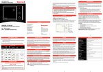
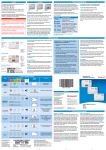
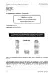
ALERT OPERATOR HANDBOOK
Siemens Traffic Controls Limited
Sopers Lane
Poole
Dorset
BH17 7ER
OPERATOR HANDBOOK
ALERT - EMERGENCY TELEPHONE SYSTEM
THIS DOCUMENT IS ELECTRONICALLY HELD AND APPROVED
PREPARED : Paula Drayson/Ruth Davis/Kelly Rocha
FUNCTION : Engineer/Technical Author/Software Engineer
DATE
: August 3, 2000
Siemens plc 1998. All rights reserved.
The information contained herein is the property of Siemens plc and is supplied without
liability for errors or omissions. No part may be reproduced or used except as authorised by
contract or other written permission. The copyright and the foregoing restriction on
reproduction and use extend to all media in which the information may be embodied.
Microsoft and Windows are registered trade marks of the Microsoft Corporation. All trade
marks recognised.
667/HB/26255/000
Issue 04.00 Page i
ALERT OPERATOR HANDBOOK
TABLE OF CONTENTS
1. INTRODUCTION.............................................................................................................................1
1.1 PURPOSE ............................................................................................................................................1
1.2 SCOPE ................................................................................................................................................1
1.3 RELATED DOCUMENTS ......................................................................................................................1
1.4 ISSUE STATE ......................................................................................................................................1
1.5 ABBREVIATIONS ................................................................................................................................1
2. HOW TO USE THIS HANDBOOK................................................................................................2
2.1 GENERAL ...........................................................................................................................................2
2.2 REINSTALLATION OF SYSTEM SOFTWARE ..........................................................................................2
3. THE OPERATOR POSITION ........................................................................................................3
3.1 THE OPERATOR SCREEN ....................................................................................................................3
3.2 THE MAP ...........................................................................................................................................6
3.3 MANUAL TEST AND FAULTS..............................................................................................................7
3.4 LOGOUT .............................................................................................................................................8
3.5 MODE KEYS.......................................................................................................................................8
3.6 SECURITY ..........................................................................................................................................8
3.6.1 Add User.....................................................................................................................................9
3.6.2 Change Password........................................................................................................................9
3.6.3 Delete User ...............................................................................................................................10
3.7 REPORTS ..........................................................................................................................................10
3.7.1 Fault Reports ............................................................................................................................11
3.7.2 Event Reports ...........................................................................................................................11
3.7.3 Call Reports ..............................................................................................................................11
3.8 HELP ................................................................................................................................................11
3.8.1 About ALERT ..........................................................................................................................11
3.8.2 Help ..........................................................................................................................................12
3.9 OPERATOR CONSOLE .......................................................................................................................13
3.9.1 Faults ........................................................................................................................................13
3.9.2 Events .......................................................................................................................................14
3.9.3 Calls ..........................................................................................................................................15
3.9.3.1 Call Annotation ...................................................................................................................................................16
3.9.3.2 Transfer ...............................................................................................................................................................17
3.9.3.3 Calls History........................................................................................................................................................19
3.10 KEYBOARD ....................................................................................................................................20
3.11 CURSOR CONTROLS .......................................................................................................................20
3.12 PRINTING .......................................................................................................................................20
4. TRAINING ......................................................................................................................................21
5. TELEPHONE OPERATION.........................................................................................................22
5.1 ANSWERING A CALL ........................................................................................................................22
5.2 MAKING A CALL ..............................................................................................................................25
5.3 CANCELLING A CALL .......................................................................................................................26
5.4 CLEARING A CALL ...........................................................................................................................26
5.5 HOLDING A CALL .............................................................................................................................27
5.6 RETRIEVING A HELD CALL ..............................................................................................................27
5.7 ANNOTATING A CALL ......................................................................................................................28
APPENDIX A REINSTALLATION OF SYSTEM SOFTWARE ................................................29
APPENDIX B ERROR CODES .......................................................................................................30
667/HB/26255/000
Issue 04.00 Page ii
Use, duplication or disclosure of data contained on this sheet is subject ot the restrictions on the title page of this document.
ALERT OPERATOR HANDBOOK
TABLE OF FIGURES
FIGURE 1 - INITIAL VIEW ..................................................................................................................4
FIGURE 2 - LOGIN WINDOW .............................................................................................................4
FIGURE 3 - MAP SHOWING PHONES ...............................................................................................5
FIGURE 4 - OPERATOR CONSOLE WINDOW .................................................................................6
FIGURE 5 - PHONE ICON MENU........................................................................................................6
FIGURE 6 - MAP SECTION MENU .....................................................................................................7
FIGURE 7 - MANUAL TEST ................................................................................................................7
FIGURE 8 - LOGOUT............................................................................................................................8
FIGURE 9 - ADD USER WINDOW ......................................................................................................9
FIGURE 10 - CHANGE PASSWORD WINDOW.................................................................................9
FIGURE 11 - DELETE USER WINDOW............................................................................................10
FIGURE 12 - REPORT OPTIONS WINDOW.....................................................................................10
FIGURE 13 - REPORT WINDOW ......................................................................................................11
FIGURE 14 - ABOUT ALERT.............................................................................................................12
FIGURE 15 - HELP TOPICS................................................................................................................12
FIGURE 16 - OPERATOR CONSOLE MODES.................................................................................13
FIGURE 17 - FAULTS MODE ............................................................................................................13
FIGURE 18 - FAULT INDICATOR.....................................................................................................13
FIGURE 19 - EVENTS MODE ............................................................................................................14
FIGURE 20 - CALLS MODE...............................................................................................................15
FIGURE 21 - CALL ANNOTATION WINDOW ................................................................................16
FIGURE 22 - TRANSFER MESSAGE WINDOW..............................................................................17
FIGURE 23 - CALLS HISTORY WINDOW .......................................................................................19
FIGURE 24 - PHONE ICON INFORMATION - INCOMING CALL.................................................22
FIGURE 25 - INCOMING CALL ON OPERATOR CONSOLE ........................................................23
FIGURE 26 - PHONE ICON MENU - ANSWER ...............................................................................23
FIGURE 27 - CONNECTED CALL ON OPERATOR CONSOLE.....................................................24
FIGURE 28 - PHONE ICON INFORMATION - ANSWERED CALL...............................................24
FIGURE 29 - RESUME CURRENT CALL MESSAGE BOX ............................................................25
FIGURE 30 - CALLING OUT FROM THE CALLS HISTORY BOX ...............................................25
FIGURE 31 - PHONE ICON MENU - CALL......................................................................................26
FIGURE 32 - PHONE ICON MENU - CANCEL ................................................................................26
FIGURE 33 - HELD CALL ON OPERATOR CONSOLE ..................................................................27
FIGURE 34 - PHONE ICON INFORMATION - HELD CALL ..........................................................27
667/HB/26255/000
Issue 04.00 Page iii
Use, duplication or disclosure of data contained on this sheet is subject ot the restrictions on the title page of this document.
ALERT OPERATOR HANDBOOK
1.
INTRODUCTION
1.1
Purpose
This handbook describes the facilities provided by the ALERT telephone system at Operator
level. It is intended to be a user manual and reference document.
1.2
Scope
This document covers the general operation of the ALERT telephone system. The
configuration of the ALERT system will determine which sections of the Handbook are
relevant.
1.3
Related Documents
Introducing Microsoft Windows 95.
1.4
Issue State
Pages
Current Issue
Type
Part ID
i to iii
04.00
AMW
667/HB/26255/000
1 to 30
04.00
AMW
667/HB/26255/000
1.5
Abbreviations
ALERT
Advanced Low power Emergency Roadside Telephone system
PC
Personal Computer
667/HB/26255/000
Issue 04.00 Page 1
Use, duplication or disclosure of data contained on this sheet is subject to the restrictions on the title page of this document.
ALERT OPERATOR HANDBOOK
2.
HOW TO USE THIS HANDBOOK
2.1
General
The prime objective of the emergency telephone system is to provide a secure and reliable
communication link between motorists and instation Operators to report accidents,
breakdowns or other problems on the highway.
The instation equipment provides the Operator interface to the roadside phones. The PC
provides all the necessary data and indications to the Operator and provides the input to
control the system. It can also interface to a fibre optic system (where fitted). Each Operator
position is equipped with a headset for conversing with motorists, the PC that displays
information about the calls and allows the Operator to control the calls, and a line interface
that performs all the communications with the outstation telephones. The instation is also
equipped with a printer for hard copies of events, fault and call reports, and a tape-recorder to
record conversations.
The Operator has control of all calls to and from the instation. All operation is by
straightforward (normally single action) menu driven mouse control.
The main body of this manual is intended for the first time user, based around images of the
actual screens that are seen by the Operator. The messages, buttons and menus that appear on
the screen and which are repeated in the text of this document are shown in bold. Section 3
describes the layout of the screen and where the Operator should find all the functions of the
system. The way the system has been set up may mean that some options are security
controlled and not available to all users. The system administrator will have further details.
Section 5 describes the telephone communication functions in detail as they are used by the
Operator.
Note: Some installations provide the Operator with a handset instead of a headset. In those
circumstances, where headset is referred to in this manual, read handset.
2.2
Reinstallation of system software
Appendix A is provided as first line maintenance if the system fails. However, it must be
remembered that whatever caused the system to fail may have corrupted data. If the
instructions contained in Appendix A have been followed and there is still a problem, contact
the system maintainer.
667/HB/26255/000
Issue 04.00 Page 2
Use, duplication or disclosure of data contained on this sheet is subject to the restrictions on the title page of this document.
ALERT OPERATOR HANDBOOK
3.
THE OPERATOR POSITION
The Operator position consists of the PC (including mouse and keyboard) and the headset.
The headset is initially inactive and only becomes active when a call is connected. If the tape
recorder is to be used to record conversations with motorists, it must be switched on and
ready to record, including having a tape in place. If necessary, refer to the tape manufacturer's
handbook for set-up instructions. The following description assumes that the PC is already
switched on and within the Windows environment. If the machine does not seem to be in
this state please refer to Appendix A. The printer must also be switched on and ready to print.
Each instation may have one or two Operator positions connected to it. The standard
configuration is one PC per instation, with a soundcard to transmit messages to motorists who
try to call in while the Operator is busy on another call. This configuration is described in this
Handbook.
Please note that due to the speed of operation of this system, there is a delay between the
function chosen and the response by the computer, e.g. there is a short delay between
answering a call and actually being able to speak to the caller.
3.1
The Operator Screen
This is a wholly Windows based system. It is operated by the standard point and click
method with the mouse, i.e. items are selected with the mouse and then the mouse button can
be used to choose from highlighted options. Menu options are selected with the right hand
mouse button, boxes and buttons are operated by clicking the left hand mouse button. A user
unfamiliar with this method of operation should refer to the manual "Introducing
Microsoft Windows 95". Note: All the windows that are part of the ALERT system are
similar to standard Windows, and can be moved around the screen to the most convenient
position for the Operator. To do this click on the blue bar at the top of the window and drag it
to the desired position.
Once the PC is within the Windows environment and the application is running, a map
similar to the example shown in Figure 1 is displayed.
667/HB/26255/000
Issue 04.00 Page 3
Use, duplication or disclosure of data contained on this sheet is subject to the restrictions on the title page of this document.
ALERT OPERATOR HANDBOOK
Figure 1 - Initial View
Click at any point on the map
and a small window appears
asking you to log in. Enter
your user name in the first
field and use the "Tab" key to
move the cursor to the
Password field. Enter your
password and select OK.
Figure 2 - Login Window
During normal operation the majority of the screen is occupied by the map depicting the road
as seen below. Once the Operator has logged in, this map shows the positions of the phones
along the road. The top of the screen is occupied by pull down menus and icons, described in
Sections 3.5 to 3.8.2.
667/HB/26255/000
Issue 04.00 Page 4
Use, duplication or disclosure of data contained on this sheet is subject to the restrictions on the title page of this document.
ALERT OPERATOR HANDBOOK
Figure 3 - Map showing Phones
The Operator Console window, as shown in Figure 4, appears on top of the map.
667/HB/26255/000
Issue 04.00 Page 5
Use, duplication or disclosure of data contained on this sheet is subject to the restrictions on the title page of this document.
ALERT OPERATOR HANDBOOK
Figure 4 - Operator Console Window
3.2
The Map
The map shows the road under control and the
phones along it. Each phone has a unique number,
shown adjacent to the phone icon on the map.
Where the map is larger than the screen size it can
be scrolled by using the scroll bars on the right
hand side and the bottom of the map area. The bar
can be clicked to progress the map or the block
within the bar can be dragged and dropped in the
way that standard Windows bars operate.
The phone icon has a menu associated with it.
Select the phone with the right hand mouse button
and the menu shown right appears.
Figure 5 - Phone Icon Menu
From this menu you can select Call, Answer, Test,
and Cancel by pointing to the item with the mouse
and clicking the left-hand button once.
Selecting Call opens the Calls History window and makes the call to the selected phone.
Once the connection is made, i.e. the phone is answered at the outstation, the call appears in
Currently Connected Call at the Operator Console.
667/HB/26255/000
Issue 04.00 Page 6
Use, duplication or disclosure of data contained on this sheet is subject to the restrictions on the title page of this document.
ALERT OPERATOR HANDBOOK
When a call is received at the instation, selecting Answer from the map menu connects caller
and Operator on the headset and the call appears in Currently Connected Call at the
Operator Console.
Cancel may be used to hang up a connected call. If the Calls History window is active on
screen, this option is not available.
The Call, Answer and Cancel functions are also available within the Operator Console and
are described in detail in Section 5. The normal method of operation is through the Operator
Console. The manual Test function is only available through the map menu, although regular
automatic testing is carried out on all phones. See Section 3.3.
Where there is more than one map to an instation, a map section menu at the top of the screen
allows the Operator to select which map to view from the list. The drop down menu allows
the Operator to select the other sections of the road. See Figure 6.
Figure 6 - Map Section Menu
3.3
Manual Test and Faults
By selecting a particular phone icon and clicking on
the right hand mouse button the phone menu appears.
From this menu select Test with the left hand button.
The selected phones text flashes and shows Testing.
If the phone changes status as a result of the test, the
information is added to the Faults list (Section 3.9.1)
and fault data is printed. This fault data is annotated
as being Operator generated. If the phone remains in
the same state as before, no record is kept of the
manual test.
All faults in the system can also be viewed by
selecting the Faults tab in the Operator Console. See
Section 3.9.1 and Figure 17.
667/HB/26255/000
Figure 7 - Manual Test
Issue 04.00 Page 7
Use, duplication or disclosure of data contained on this sheet is subject to the restrictions on the title page of this document.
ALERT OPERATOR HANDBOOK
3.4
Logout
The Logout button on the Operator Console returns the Operator to the
initial state (Figure 1).
The system asks for confirmation, as shown
in
Figure 8, before logging out. Trying to log
out while a call is still connected or held
generates a warning message. Clear all calls
and then try again.
Figure 8 - Logout
3.5
Once the Operator has logged out, the
system is still running, but no actions may
be taken until a user has successfully logged
back in.
Mode Keys
The mode keys are placed at the top left-hand corner of the screen and should be clicked to be
actioned. The current mode is shown at the foot of the screen, as seen in Figure 3.
Information mode. This is the standard operating mode that the Operator is automatically
placed in when logged in. Unless otherwise indicated, the Operator Handbook assumes that
the Operator is in Information mode.
Add mode. This mode is provided so that new phones can be placed onto the map. This
function adds a new phone to the database and should therefore be used with caution.
Move mode. This mode works in conjunction with add mode and allows the newly
placed phone to be moved in relation to the road.
Update Database. This mode should be used when a new phone has been added or moved.
Selecting this icon automatically carries out a background update of the database.
3.6
Security
The Security drop down menu allows the user to select either Add User, Change Password
or Delete User function.
667/HB/26255/000
Issue 04.00 Page 8
Use, duplication or disclosure of data contained on this sheet is subject to the restrictions on the title page of this document.
ALERT OPERATOR HANDBOOK
3.6.1 Add User
Figure 9 - Add User Window
To add a new user to the database, enter the full name, the user name, the password and
password verification and access level in the appropriate spaces. Access Levels can be se to 0,
1 or 2. Level 2 gives the user access to all the menues (supervisors usually have Level 2
access). Level 0 and 1 hide the Add User and Delete User menues (operators usually have
these access rights).Use the "Tab" key to move from one area of the screen to the next.
Confirm the entry by selecting OK. Clicking on Cancel closes the window without saving
any entry.
3.6.2 Change Password
Figure 10 - Change Password Window
This function allows the current user to change their password. Enter the current password,
and then the new password twice where indicated. Use the "Tab" key to move from one area
of the screen to the next. Confirm the entry by selecting OK.
667/HB/26255/000
Issue 04.00 Page 9
Use, duplication or disclosure of data contained on this sheet is subject to the restrictions on the title page of this document.
ALERT OPERATOR HANDBOOK
To change the password for another user, first log out of the system and log in again as the
user whose password is to be changed. Then proceed as described above.
3.6.3 Delete User
Figure 11 - Delete User Window
If the user that is logged in has access to this function it will allow the current user to delete
another users logon. Select the user you wish to delete and confirm your choice by selecting
OK. The function will not allow you to delete the entry you are logged in as. Clicking on
Cancel closes the window without deleting any entry.
3.7
Reports
The Report drop down menu allows the user to produce a report covering the required period.
Select Daily, Weekly, Monthly or Annually from the list. A daily report covers the day from
00:00:01 to the current time. Weekly, monthly and annual reports take data from the current
week, month or year up to the date and time the report is compiled.
Figure 12 - Report Options Window
The report may be for Faults, Events or Calls as described below. Once the period to be
covered and type of report are chosen, the report is compiled and appears on screen after a
short delay. If the window containing the report is too small to view the data, drag it to size. If
the report generated is over certain number of records, the report is split into pages, which can
667/HB/26255/000
Issue 04.00 Page 10
Use, duplication or disclosure of data contained on this sheet is subject to the restrictions on the title page of this document.
ALERT OPERATOR HANDBOOK
be scrolled through (backwards and forwards) using the Previous Page or Next Page buttons.
A page may be printed by selecting the Print Page button. The report may be printed by
selecting the Print Report button. Select Cancel to close the window.
Figure 13 - Report Window
3.7.1 Fault Reports
This report shows the dates, times and ID of phones where a fault was reported, whether
system generated or Operator requested, with the fault codes, and fault clearances. These
details are also given in the Event Report.
3.7.2 Event Reports
This report provides a System Log of all activity on the system, including the faults that
appear in the Fault Report described above, and call activity shown in the Call Report
described below. Events listed in this report include system re-starts, Operators logging in and
out of the system, activities relating to a call from recognition by the system to disconnection
and faults and fault clearances for all phones.
3.7.3 Call Reports
This report provides a simple list of calls to and from each phone with the date and time the
call was instigated, Operator name, call type, the phone ID and any information added to the
Call Annotation screen.
3.8
Help
3.8.1 About ALERT
This view only screen shows details of the version of ALERT on the system.
667/HB/26255/000
Issue 04.00 Page 11
Use, duplication or disclosure of data contained on this sheet is subject to the restrictions on the title page of this document.
ALERT OPERATOR HANDBOOK
Figure 14 - About ALERT
3.8.2 Help
The Help menu shows
an
alphabetically
arranged
list
of
subjects on which help
is available. Click on
the topic and then
Display to display the
help text.
To find help on a
particular
subject,
click on the Find tab
and enter text in the
box. If help is
available on the entry,
it is displayed.
Press the Print button
to print the contents of
the displayed page.
Figure 15 - Help Topics
667/HB/26255/000
Issue 04.00 Page 12
Use, duplication or disclosure of data contained on this sheet is subject to the restrictions on the title page of this document.
ALERT OPERATOR HANDBOOK
3.9
Operator Console
The Operator Console is where most of the system's operations are activated. At the top of
this window the currently logged in Operator's name is displayed. The Console can be in one
of three modes: Calls, Faults and Events. These are selected by clicking one of the tabs as
shown in Figure 16.
Figure 16 - Operator Console Modes
3.9.1 Faults
Faults displays the
faults currently in the
system with the most
recent at the end of
the list (Figure 17).
To generate a Fault
Report, see section
3.7.1.
Figure 18 - Fault Indicator
Figure 17 - Faults Mode
If the Operator is in
Calls or Events, a
red box appears on
the Faults tab when
a new fault is
detected by the
system.
A test signal is directed down the line at regular intervals. If a fault or fault clearance is
detected an error code is generated and the details appear in the Faults area of the Operator
Console with the note SYSTEM TEST.
If a manual test (Section 3.3) detects a fault or fault clearance the details are also added to the
Faults list with the note OPERATOR TEST.
667/HB/26255/000
Issue 04.00 Page 13
Use, duplication or disclosure of data contained on this sheet is subject to the restrictions on the title page of this document.
ALERT OPERATOR HANDBOOK
The main error codes are described in Appendix B.
The only Operator action possible as a result of the error codes above is where a line fault is
indicated by Error Code 1, 2 or 3. Check the phone line connections with the instation and
then carry out a manual test on the phone. If the fault clears no further action is necessary.
If the line fault is still indicated, or any other fault is shown, call the maintenance engineer.
3.9.2 Events
Events
lists
shows
the
historical events
of the system,
such as times of
conversations,
with the most
recent at the
bottom.
See
example in
Figure 19.
To
run
an
Events Report,
see
section
3.7.2.
667/HB/26255/000
Figure 19 - Events Mode
Issue 04.00 Page 14
Use, duplication or disclosure of data contained on this sheet is subject to the restrictions on the title page of this document.
ALERT OPERATOR HANDBOOK
3.9.3 Calls
Calls is the standard mode that the Operator uses. The call mode has a number of buttons as
shown below.
Figure 20 - Calls Mode
An incoming call is listed in the Incoming Calls box (see Figure 20). To answer a call it must
be highlighted in the Incoming Calls box; the first call is automatically highlighted. Select
the Answer button. This moves the call to the Currently Connected Call box. The Operator
is connected to the caller through the headset after a short delay.
To put a caller on hold, select the Hold button. See Section 5.5 for a description of the Hold
function. To take a caller off hold the call has to be selected in the Held Calls box. If there
are a number of calls on hold, only one is highlighted. This call is reconnected first (unless
the order of reconnection is changed by selecting another call within the box) by pressing the
Connect button. To disconnect a call it needs to be the Currently Connected Call i.e. not on
hold, then the Hang up button is pressed.
Where the Operator is dealing with a currently connected call and an incoming call is
detected, the incoming caller hears a message to indicate that the call will be answered as
soon as possible.
667/HB/26255/000
Issue 04.00 Page 15
Use, duplication or disclosure of data contained on this sheet is subject to the restrictions on the title page of this document.
ALERT OPERATOR HANDBOOK
3.9.3.1 Call Annotation
The annotation function is for the Operator to add notes to the currently connected call, so
that the information is noted for future reference. By pressing the Annotate button a new
window appears (see below) in which the details of the phone call are automatically entered.
Incident # is not in use for this version of the software.
The Operator, Reported and Location details are taken from the Calls window.
Action contains a drop down menu from which to select the action to be taken as a result of
the call.
The remainder of the window contains free text boxes in which the Operator can type
additional information. Details entered here are included in Call Reports. See Section 3.7.3.
The Operator can also print out the Call Annotation window by selecting the print icon on
the right-hand side of the window. Pressing the Cancel button returns the Operator to the
Operator Console without saving any entry in the window. To save the details and close the
window, press the OK button.
Figure 21 - Call Annotation Window
667/HB/26255/000
Issue 04.00 Page 16
Use, duplication or disclosure of data contained on this sheet is subject to the restrictions on the title page of this document.
ALERT OPERATOR HANDBOOK
3.9.3.2 Transfer
Where there is more than one instation to a system, one of the instations can be the controller
(higher instation), whilst the other instations act as slave instations (lower instations). This
arrangement allows transfer of all the telephones from the selected lower instation to the
higher instation. Transfer or cancellation of transfer can only be initiated at the Lower
Instations using the attached ALERT Transfer Box.
Figure 22 - Transfer Message Window
If the switch is changed from Lower Instation Control to Higher Instation Control and the
criteria below is met, transfer of the section should be completed successfully. A message box
will fill the screen informing the operator that transfer has been completed, and will stay on
the screen until cancellation of transfer has been completed successfully. If transfer does not
complete the Pending LED will light up, and the Lower Instation will remain in control until
the transfer can complete.
667/HB/26255/000
Issue 04.00 Page 17
Use, duplication or disclosure of data contained on this sheet is subject to the restrictions on the title page of this document.
ALERT OPERATOR HANDBOOK
Using one of the following sets of criteria, transfer can be completed successfully…
1)
On the ALERT Transfer Box check that…
The Higher Instation is available (Higher Instation OK LED is lit)
AND the Lower Instation does not have a call (Line Clear LED is lit)
AND the switch is set to Higher Instation control
OR
2)
On the ALERT Transfer Box check that…
The Higher Instation is available (Higher Instation OK LED is lit)
AND the Lower Instation is not available (Lower Instation OK LED is not lit)
AND the switch is set to Higher Instation control
If the switch is changed from Higher Instation Control to Lower Instation Control and the
criteria below is met, cancellation of transfer for the section should be completed
successfully. If the user clicks on the map, a login window will appear, for the user to log on.
If the operator enters valid data, and the criteria below is met, cancellation of transfer should
be completed successfully and the map and phones should re-appear at the Lower Instation. If
the cancellation of transfer does not complete the Pending LED will light up, and the Higher
Instation will remain in control until the cancellation of transfer can complete.
Using one of the following sets of criteria, cancellation of transfer can be completed
successfully…
1) On the ALERT Transfer Box check that…
The Higher Instation is available (Higher Instation OK LED is lit)
AND the Higher Instation does not have a call (Line Clear LED is lit)
AND the Lower Instation is available (Lower Instation OK LED is lit)
AND the switch is set to Lower Instation control
OR
2) On the ALERT Transfer Box check that…
The Higher Instation is not available (Higher Instation OK LED is not lit)
AND the Lower Instation is available (Lower Instation OK LED is lit)
AND the switch is set to Lower Instation control
667/HB/26255/000
Issue 04.00 Page 18
Use, duplication or disclosure of data contained on this sheet is subject to the restrictions on the title page of this document.
ALERT OPERATOR HANDBOOK
3.9.3.3 Calls History
The Operator can initiate a call (ring out) to a phone by selecting the Call button. Pressing the
Call button activates the Calls History window, which allows the Operator to call one of the
phones listed. Any Currently Connected Call is placed on Hold.
The Calls History window
(see right) shows the latest call
from each phone into the
instation. This list is arranged
in historical order, with the
latest at the end of the list. To
call out, highlight the relevant
phone from the list and press
the Call button. The Operator
can cancel the call before it is
answered by pressing the
Cancel Call button. The
Close button closes the
window.
Figure 23 - Calls History Window
To call a phone that is not in the list i.e. it has not phoned in to the instation, first make sure
that the Calls History window is closed. Select the relevant phone icon from the map (as
described in section 3.2) to activate the hidden menu. From the menu select Call, which
activates the Calls History window and makes the call.
667/HB/26255/000
Issue 04.00 Page 19
Use, duplication or disclosure of data contained on this sheet is subject to the restrictions on the title page of this document.
ALERT OPERATOR HANDBOOK
3.10
Keyboard
The keyboard is only used where text is to be entered, e.g. the Call Annotation window. The
system is mainly based upon mouse usage.
3.11
Cursor Controls
The arrow keys can be used to move between pull down menus for the selection of functions.
3.12
Printing
The printer automatically prints out every event that takes place on the system, e.g. when
Operators log on and off, and when a phone call is cancelled or hung-up. Any operator or
background test also generates printed fault data if the tested phone changes status as a result
of the test, i.e. a previously faulty phone becomes OK, or a working phone is found to be
faulty. Notes entered in the Call Annotation window may also be printed if required. See
Figure 21.
To print periodic reports, follow the instructions contained in Section 3.7 to generate a report,
and then select either the Print Page or Print Report option while the report is on screen.
667/HB/26255/000
Issue 04.00 Page 20
Use, duplication or disclosure of data contained on this sheet is subject to the restrictions on the title page of this document.
ALERT OPERATOR HANDBOOK
4.
TRAINING
There is no on-line training facility available for the ALERT emergency telephone system.
667/HB/26255/000
Issue 04.00 Page 21
Use, duplication or disclosure of data contained on this sheet is subject to the restrictions on the title page of this document.
ALERT OPERATOR HANDBOOK
5.
TELEPHONE OPERATION
This section describes the normal use of the system by the Operator. Due to the speed of
operation of this system, there is a short delay between the function chosen and the response
by the computer, e.g. there is a short delay between answering a call and actually being able
to speak to the caller.
5.1
Answering a Call
When a motorist initiates a call by lifting the
handset or pressing the call button at the
roadside phone, the computer identifies the
new call. On the screen the specific phone
text flashes and is identified as an Incoming
Call. The Answer button on the Operator
Console also flashes.
Figure 24 - Phone Icon Information Incoming Call
If there is a Currently Connected Call
already, the caller hears a message until the
Operator takes the new call.
If an incoming call has not been answered after about 90 seconds, the phone times out and the
caller no longer hears the ringing tone. The Answer button continues to flash at the Operator
Console; to respond to the call the Operator clicks the Answer button. The phone then starts
to ring.
667/HB/26255/000
Issue 04.00 Page 22
Use, duplication or disclosure of data contained on this sheet is subject to the restrictions on the title page of this document.
ALERT OPERATOR HANDBOOK
To accept the
call press the
Answer button.
Figure 25 - Incoming Call on Operator Console
The Operator can also answer this call by
selecting the phone with the right hand mouse
button so that the pop up menu appears. From
this menu select Answer. Then proceed as
described below.
Figure 26 - Phone Icon Menu - Answer
667/HB/26255/000
Issue 04.00 Page 23
Use, duplication or disclosure of data contained on this sheet is subject to the restrictions on the title page of this document.
ALERT OPERATOR HANDBOOK
The
call
information
moves from the
Incoming Call
box
to
the
Currently
Connected Call
box.
The
Operator is now
connected to the
caller on the
headset.
Figure 27 - Connected Call on Operator Console
The phone icon on the map now shows
Answered.
Figure 28 - Phone Icon Information Answered Call
Built in to the system is a Call Timeout so that any call connected for longer than the
specified time is asked if the Operator wishes to resume the call (see below). Note: The call
timeout refers to the call that has been connected the longest, which may not be the currently
connected call. Select Yes to keep the connection, or No to hang up the call. This time period
is
configurable
by
the
system
maintainer.
667/HB/26255/000
Issue 04.00 Page 24
Use, duplication or disclosure of data contained on this sheet is subject to the restrictions on the title page of this document.
ALERT OPERATOR HANDBOOK
Figure 29 - Resume Current Call Message Box
5.2
Making a Call
The Operator can call any
telephone on the road by
selecting the Call button
(below) from the Console.
This shows the Calls
History (left) for the
system and also has a Call
button that allows the
Operator to call the phone.
Figure 30 - Calling Out from the Calls History Box
The Calls History window normally displays details of the most recent call from each phone.
From the list highlight the phone to be called and select the Call button.
667/HB/26255/000
Issue 04.00 Page 25
Use, duplication or disclosure of data contained on this sheet is subject to the restrictions on the title page of this document.
ALERT OPERATOR HANDBOOK
The Operator can also select the required
phone on the map with the right hand mouse
button so that the pop up menu appears, as
shown on the right. From this menu select
Call. The Calls History window appears with
the selected phone details entered and the call
is made.
Figure 31 - Phone Icon Menu - Call
5.3
Cancelling a Call
The Calls History window has a Cancel option. An outgoing call can only be cancelled
before it is answered. Once a connection is made, the call must be cleared as described in
Section 5.4.
5.4
Clearing a Call
When the call is finished the Operator must use the Hang Up
function to clear the call. This only clears the current call. The call
must be displayed in the Currently Connected Call box to be hung
up. It does not clear any held calls.
The Operator can also select the required
phone on the map with the right hand mouse
button so that the pop up menu appears, as
shown on the right. From this menu select
Cancel. This will clear the current call.
Figure 32 - Phone Icon Menu Cancel
Another way of disconnecting a call is to select No when the Call Timeout window is
displayed. See Figure 29. This call does not need to be the Currently Connected Call to be
hung up.
667/HB/26255/000
Issue 04.00 Page 26
Use, duplication or disclosure of data contained on this sheet is subject to the restrictions on the title page of this document.
ALERT OPERATOR HANDBOOK
5.5
Holding a Call
Putting a call on hold means that the phone connection with the Instation is still established,
but caller and Operator cannot communicate with each other. The motorist hears a tone to let
him know that the call is not finished. While a call is held the Operator is free to deal with
other calls. When a call is taken off hold, the motorist and Operator are re-connected.
An instance where Hold may need to be used is where an Incoming Call needs to be
answered and the Operator is already dealing with a Currently Connected Call. The
Operator should tell the motorist that the call is to be placed on Hold.
The Operator can
hold the call in
progress at any
time by using the
Hold button.
The call is now
displayed in the
Held Calls box.
Figure 33 - Held Call on Operator Console
If the Operator chooses to Answer an incoming call
when there is already a Currently Connected Call, the
computer automatically holds the current call and its
details move to the Held Calls box.
Figure 34 - Phone
Information - Held Call
5.6
The new call details move to the Currently Connected
Icon Call Box.
The phone icon now shows the original call as Held.
Retrieving a Held Call
667/HB/26255/000
Issue 04.00 Page 27
Use, duplication or disclosure of data contained on this sheet is subject to the restrictions on the title page of this document.
ALERT OPERATOR HANDBOOK
To reconnect to a call within the Held Calls box, first make sure that the
call is highlighted by clicking on the text in the Held Calls box. Then
select the Connect button. This moves the call from the Held Calls box
to the Currently Connected Call box and the Operator and caller are
reconnected on the headset.
If there is a Currently Connected Call and the Operator reconnects a call that is on hold,
then the Currently Connected Call automatically goes onto hold.
5.7
Annotating a Call
By clicking on the Annotate button a free text window appears (see
Section 3.9.3.1 and Figure 21). The Operator can now type in notes
about the current call, including the distance from the phone to the
incident being reported, the caller's name and any further information
required. The Action drop down menu enables the Operator to choose
from a list of actions being taken as a result of the call.
667/HB/26255/000
Issue 04.00 Page 28
Use, duplication or disclosure of data contained on this sheet is subject to the restrictions on the title page of this document.
ALERT OPERATOR HANDBOOK
Appendix A
Reinstallation of system software
This section is provided so that in the unlikely event of failure of the system it can be
recovered. If it is not possible to follow the instructions exactly, because the system shows
discrepancies with the following instructions and replies, notify the maintenance organisation
immediately as there may have been some lower level corruption of the system.
Case A.1
If the Operator has a problem with the system, the Operator's actions should be:
1. Logout of the ALERT Telephone system (Section 3.4).
2. Switch the PC off.
3. Ensure that all cables going to the back of the PC are securely in place.
4. Switch the PC back on again.
5. This last action automatically starts up the ALERT application, and presents the Operator
with the map as shown in Figure 1. Login in the usual way.
If there is still a fault in the system, please check that the above actions have been completed
correctly. Then check all cable connections into the PC and the Instation Line Interface box.
If these checks have been completed satisfactorily and there is no known fault in any other
part of the system, then the problem is likely to be a lower level data corruption. In this case,
notify the system maintainer.
667/HB/26255/000
Issue 04.00 Page 29
Use, duplication or disclosure of data contained on this sheet is subject to the restrictions on the title page of this document.
ALERT OPERATOR HANDBOOK
Appendix B
Error Codes
The codes are made up as follows:
1
fault on line 1
2
fault on line 2
4
battery is faulty on line 1
8
DC voltage is low on line 1
16
Cross-Talk
32
battery is faulty on line 2
64
DC voltage is low on line 2.
128
Cross-Talk
Examples of how the Error Codes are built up:
Example 1.
If Error Code 1 is displayed, this shows there is a fault on Line 1(1).
If Error Code 2 is displayed, this shows there is a fault on Line 2(2).
If Error Code 3 is displayed, this shows there is a fault on Line 1 and Line 2 (1 and 2).
Example 2.
If Error Code 13 is displayed, this shows there is a fault on Line 1(1), a battery fault on Line
1(4) and DC voltage is low on Line 1(8).
Example 3.
If Error Code 98 is displayed, this shows there is a fault on Line 2(2), a battery fault on Line
2(32) and DC voltage is low on Line 2(64).
Example 4.
If Error Code 29 is displayed, this shows cross talk on Line 1(16), with DC voltage is low on
Line 1(8), battery is faulty on Line 1(4) and a fault on Line 1(1).
Example 5.
If Error Code 226 is displayed, this shows cross talk on Line 2(128), with DC voltage is low
on Line 2(64), battery is faulty on Line 2(32) and a fault on Line 2(2).
667/HB/26255/000
Issue 04.00 Page 30
Use, duplication or disclosure of data contained on this sheet is subject to the restrictions on the title page of this document.