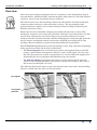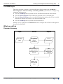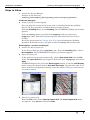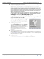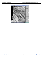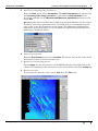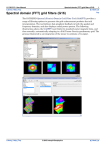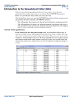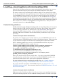
1
INTREPID User Manual
Library | Help | Top
Levelling—decorrugation and microlevelling (G14)
1
| Back |
Top
Levelling—decorrugation and microlevelling (G14)
After tie line levelling our data to remove non-geological data artifacts, we can now
proceed to the final stage of processing of our airborne magnetic survey data.
We want to remove any remaining data artifacts which are not geological in origin
but are the result of the data acquisition procedure. This process is generally referred
to as levelling. We have already used a rigorous method called tie line levelling to
remove most of the artifacts. In this tutorial we use the INTREPID Decorrugation
and MicroLevel tools to perform the final step in our processing sequence, which is a
type of filtering designed to remove any remaining linear short wavelength artifacts.
These artifacts are visible as corrugations in the gridded data. This procedure is
commonly referred to as microlevelling.
Context of this guided tour
In the context of your data processing cycle, microlevelling follows the magnetic
diurnal correction, GRF removal, and tie line levelling. This Guided Tour assumes
you have already completed the Introduction to the Spreadsheet Editor (G03),
removed the GRF component (G16), tie line levelled your data (G19), and have a
diurnally GRF corrected and tie line levelled field in your dataset, ready for final
processing.
Location of sample data for Guided Tours
We provide two complete sets of sample datasets, one in INTREPID format and one
in Geosoft format. INTREPID works equally well with both formats. When you want
to open a dataset, navigate to the directory containing the required data format.
Where install_path is the path of your INTREPID installation, the project
directories for the Guided Tours sample data are
install_path\sample_data\guided_tours\intrepid_datasets and
install_path\sample_data\guided_tours\geosoft_datasets.
For example, if INTREPID is installed in
C:\Program Files\Intrepid\Intrepid4.5.nnn,
then you can find the INTREPID format sample data at
C:\Program Files\Intrepid\Intrepid4.5.nnn\sample_data\
guided_tours\intrepid_datasets
This is the default location for the sample data. If you have installed INTREPID
normally, the data resides there. If you have installed INTREPID elsewhere, the
exercises will work just as well. Just use the appropriate pathnames.
For more information about installing the sample data, see "Sample datasets—
installing, locating, naming" in INTREPID Guided Tours Introduction (G01)
For a more detailed description of INTREPID datasets, see Introduction to the
INTREPID database (G20). For even more detail, see INTREPID database, file and
data structures (R05).
Location of sample data for CookBooks
Right next to the Guided tours data, is a rich set of more exotic geophysics datasets
and grids, already prepared for the cookbook training sessions. A casual user might
Library | Help | Top
© 2012 Intrepid Geophysics
| Back |
INTREPID User Manual
Library | Help | Top
Levelling—decorrugation and microlevelling (G14)
2
| Back |
also gain some trial and error insights into the capbilities of the software, just by
testing the Project Manger’s ability to preview and describe the attributes of each of
the cookbook datasets.
Library | Help | Top
© 2012 Intrepid Geophysics
| Back |
INTREPID User Manual
Library | Help | Top
Levelling—decorrugation and microlevelling (G14)
3
| Back |
Overview
Our aim in processing aeromagnetic data is to produce a time-independent map of
local anomalies, with the Earth’s regional magnetic field removed, and with artifacts
caused by errors in the acquisition process removed.
The effectiveness of tie line levelling is limited by the number of tielines (and thus
crossover points) which are collected during a survey. The wavelength of nongeological features which can be removed using tie line levelling is limited by the
distance between tie lines.
Before the advent of affordable imaging processing software and accurate GPS
navigation, magnetic survey data was routinely contoured as a final product. At this
level of data presentation, tie line levelling was generally sufficient to remove
artifacts from the line data. Routine enhanced imaging processing brought about the
need to remove remaining residual errors after standard processing and tie line
levelling. Micro-levelling is a general term that fulfils this requirement.
The INTREPID implementation of microlevelling is a two stage operation, beginning
with a grid created from the tie-line levelled data.
•
The Decorrugation tool uses filtering to remove corrugations from a grid and
creates a grid without corrugations, which we call a levelled grid. You can tune
the filter parameters to remove corrugations of a certain width and length, thus
minimising the loss of geological information from your dataset.
•
The Microlevelling tool applies corrections to a line dataset based upon the
values in the levelled grid. Each data point is adjusted according to the value of
the nearest levelled grid cell value.
The following illustration shows a grid created from some data before microlevelling
and one created after the data was microlevelled.
Corrugation
Corrugation
removed
Before microlevelling
Library | Help | Top
After microlevelling
© 2012 Intrepid Geophysics
| Back |
INTREPID User Manual
Library | Help | Top
Levelling—decorrugation and microlevelling (G14)
4
| Back |
The GDMG cycle
The steps required to obtain a microlevelled data field comprise the Gridding—
Decorrugation—Microlevelling—Gridding (GDMG) cycle. Here is a step by step
summary of the process:
1
Use the Gridding tool to grid the tie line levelled field from the line dataset.
2
Use the Decorrugation tool to filter the grid and create a levelled grid.
3
Use the Microlevelling tool to use the levelled grid to adjust the tie line levelled
field in the dataset and create a new microlevelled field.
4
Use the Gridding tool to grid the microlevelled field.
Finally, use an appropriate visualisation tool to compare the tie line levelled grid to
the microlevelled grid.
What you will do
Flowchart Summary
Inputs
Process
Outputs
Grid of Raw
Data
Decorrugation
tool produces
"Grid of
Corrections"
Grid of
Corrections
Microlevelling tool
applies "Grid of
Corrections to Line
data set
New
corrected
field in Line
dataset
Regrid using
new corrected
Field
Library | Help | Top
© 2012 Intrepid Geophysics
| Back |
INTREPID User Manual
Library | Help | Top
Levelling—decorrugation and microlevelling (G14)
5
| Back |
Steps to follow
1
Launch the Project Manager
Navigate to the directory
install_path\sample_data\guided_tours\intrepid_datasets.
Create the input grid
2
Create a grid to be decorrugated
(You can skip this section if you do not wish to actually perform the gridding
process. We have provided a solution dataset for this section.)
From the Gridding Menu, launch Gridding. The INTREPID Gridding tool window
appears.
From the albury dataset, grid the field magdpoly and save the grid as
magdpoly1.ers. This field contains magnetic data which has been tie line
levelled.
Recall the instructions in Creating grids (G07) for performing the Gridding
operation. Remember to place the grid outside the albury dataset directory.
Decorrugation—create a levelled grid
3
Launch the Decorrugate tool
In the Project Manager select magdpoly.ers. From the Levelling Menu, choose
Decorrugation. The INTREPID Decorrugate tool window appears.
4
Open the input grid
(If the grid has not opened automatically, choose Open Input Grid from the File
menu. The Open Grid dialog box appears. Select the grid magdpoly1 and choose
Open. )
INTREPID displays the grid in the Decorrugate window. From the Grid Display
menu, change the display mode to Grid with Sun Angle. You should be able to see
linear artifacts (corrugations) running across the dataset. These are the features
we want to remove.
5
Specify the output grid
From the File menu, choose Specify Output Grid. The Save Output Grid dialog
box appears. Type decorr and choose Save.
Library | Help | Top
© 2012 Intrepid Geophysics
| Back |
INTREPID User Manual
Library | Help | Top
6
Levelling—decorrugation and microlevelling (G14)
6
| Back |
Set the decorrugation filter parameters
Quick review: The Decorrugation tool is designed to remove features with
specific characteristics. Therefore you should select filter parameters that remove
corrugations only and do not remove geophysical information. A good rule of
thumb is to make the filter width at least twice the aquisition line spacing, and
the filter length between 5 and 10 times the line spacing. In practice you may find
that decorrugations are significantly shorter than this if they are caused by, for
exampe, aircraft clearance variations.
The albury dataset has an average acquisition line spacing of about 200m and a
tie line spacing of 1000 and 2000m. Therefore as a starting point we can set the
Streak Width to 600m and the Min Streak Length to 1600m.
From the Filter menu choose Parameters. The Filter Parameters box appears. Set
the Min Streak length to 1600 and the Streak width to 600. Accept the defaults for
the other parameters and choose OK.
The decorrugator can only operate in one of two
directions—either NS (grid columns) or EW
(grid rows). For this dataset we decorrugate
along grid rows, so accept the default setting.
7
Select the grid output mode
From the Grid Output menu choose Levelled.
Note: you can output either a Levelled or a
Corrections grid. A levelled grid is easier to
examine visually before you proceed to
microlevelling. Otherwise the choice is not
important.
8
Apply the decorrugation filters
Choose Apply. The process proceeds. When completed the levelled grid displays in
in the Decorrugate window. Examine the results. If you want to examine just the
corrcetions, repeat 7 & 8 again.
9
Exit from the tool.
To exit from the Decorrugate tool, choose Quit from the File menu.
Library | Help | Top
© 2012 Intrepid Geophysics
| Back |
INTREPID User Manual
Library | Help | Top
Library | Help | Top
Levelling—decorrugation and microlevelling (G14)
7
| Back |
© 2012 Intrepid Geophysics
| Back |
INTREPID User Manual
Library | Help | Top
Levelling—decorrugation and microlevelling (G14)
8
| Back |
Microlevelling—apply the levelled grid adjustments to the line data
1
Launch the Microlevelling tool
From the Project Manager Levelling Menu, launch MicroLevelling. The
INTREPID Microlevel tool window appears.
2
Open the input dataset and field
From the File menu, choose Specify Dataset—Open Original Signal. The Select
Database dialog box appears. Select the dataset albury..DIR and choose Open.
The Select Signal Field dialog box appears. Select magdpoly from the list of
dataset fields and choose OK. If you already have X,Y and Linetype assigned as
INTREPID alises, an information box appears. Choose OK.
3
Select the input grid
From the File menu, choose Open Input Grid. The Open Grid dialog box appears.
Select the grid decorr which you created earlier, and choose Open. INTREPID
displays the grid in the Microlevel window.
4
Specify the output field name
From the File menu, choose Specify Corrected Signal. The Save Corrected Signal
dialog box appears. Click in the Enter New Field Name text box and delete
levelledZ. Now type magfinal for the new field name. Choose OK.
Library | Help | Top
© 2012 Intrepid Geophysics
| Back |
INTREPID User Manual
Library | Help | Top
5
Levelling—decorrugation and microlevelling (G14)
9
| Back |
Set the microlevelling filter parameters
From the Filter menu choose Parameters. The Filter Parameters box appears. Set
the Secondary filter along correction to 1600 and the Nominal Strike to 90.
Accept the defaults for the Minimum and Maximum adjustment parameters and
choose OK.
Quick review: The secondary filter length depends upon whether you are using a
levelled or corrections grid format. For a levelled grid, we recommend using the
same value as the Decorrugation streak length. The Minimum and Maximum
adjustment parameters allow you to constrain the microlevelling adjustment to
within these amplitude limits.
6
Select the grid format
From the Grid Format menu choose Levelled. The format must be the same as the
grid format chosen in the Decorrugate tool.
7
Apply the microlevelling process
Choose Apply. As the process proceeds INTREPID displays the flight lines with
colours corresponding to the adjustment values being made to the field magdpoly.
8
Exit from the tool.
To exit from the Microlevel tool, choose Quit from the File menu.
Library | Help | Top
© 2012 Intrepid Geophysics
| Back |
INTREPID User Manual
Library | Help | Top
Levelling—decorrugation and microlevelling (G14)
10
| Back |
Grid the microlevelled result and compare it to the grid before decorrugation
1
Grid the microlevelled field
From the Gridding Menu, launch Gridding. The INTREPID Gridding tool window
appears.
From the albury dataset, grid the field magfinal and save the grid as
magfinal.ers. This field contains magnetic data which has been microlevelled.
Recall the instructions in Creating grids (G07) for performing the Gridding
operation. Remember to place the grid outside the albury dataset directory.
2
Examine the grids before and after microlevelling
Using the Visualisation tool, examine the ‘before and after’ grids magdpoly and
magfinal. (See Visualisation tools(G05)). Note the absence of the linear
corrugations in magfinal.
Library | Help | Top
© 2012 Intrepid Geophysics
| Back |
INTREPID User Manual
Library | Help | Top
Levelling—decorrugation and microlevelling (G14)
11
| Back |
Key points for this guided tour
In this guided tour you have used the Decorrugation, Microlevelling and Gridding
tools to:
•
Create a levelled grid with corrugations removed (Decorrugation)
•
Use the levelled grid to create a new microlevelled field in the line dataset
(Microlevelling)
•
Create a microlevelled grid from the microlevelled field (Gridding)
Congratulations! You have successfully processed the magnetic data from the albury
airborne geophysical dataset.
Frequently Asked Questions
Q : Can I apply these methods to a subsection of a grid?
A : Yes. You can use the Subsection tool to define a grid of just the required area. You
can then decorrugate this smaller grid. When you apply the levelled grid changes to the
line dataset using the Microlevelling tool, it only makes adjustments to areas covered
by the levelled grid. Alternatively, we have added a subsection block into the batch
language, including the new V5.0 protobuf form, to support this funtion directly in this
tool.
Q : Can I use rotated grids in this tool?
A : Yes. The Decorrugation tool can only decorrugate E-W or N-S oriented features
(grid rows or columns), and so for survey lines flown at an angle it is necessary to
rotate the grid before decorrugating it. The Microlevelling tool can handle rotated
levelled grids.
Q : Do these tools only work with magnetic data?
A: No. Decorrugation and Microlevelling can be applied to different types of data,
including digital terrain models, radiometrics, and EM data. However, there is only
support for one component of the signal at a time. We have not tackled upgrading these
tools for vector/tensor use directly.
Library | Help | Top
© 2012 Intrepid Geophysics
| Back |