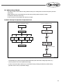
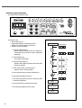
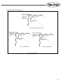
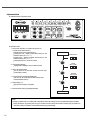
1
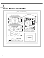
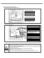
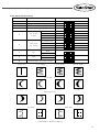
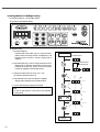
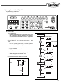
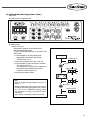
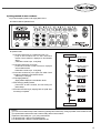
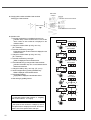
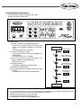
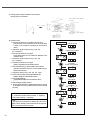
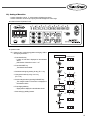
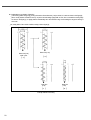
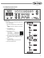
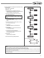
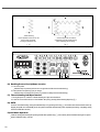
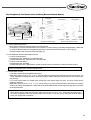
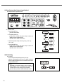
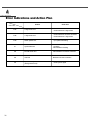
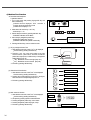
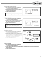
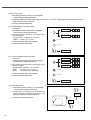
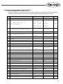
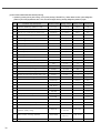
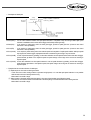
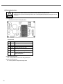
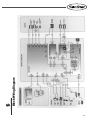
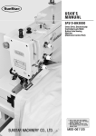
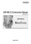
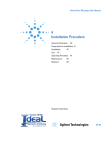
R
USER S MANUAL
KM-2070P SERIES
Electronically Controlled
1-Needle ZigZag Lock
Stitch Machine
Electronic Control Part
lity
a
u
tQ
Besst Pricevice
Be st Ser
Be
1. Thank you for purchasing our product. Based on the rich expertise and
experience accumulated in industrial sewing machine production, SUNSTAR
will manufacture industrial sewing machines, which deliver more diverse
functions, high performance, powerful operation, enhanced durability, and
more sophisticated design to meet a number of user’s needs.
2. Please read this user’s manual thoroughly before using the machine. Make
sure to properly use the machine to enjoy its full performance.
3. The specifications of the machine are subject to change, aimed to enhance
product performance, without prior notice.
4. This product is designed, manufactured, and sold as an industrial sewing
machine. It should not be used for other than industrial purpose.
R
SunStar CO., LTD.
Contents
1. Internal Structure of Control Box
4
2. Connection of Power Voltage and Control Box Cable
5
1) Power Voltage and Power Code Connection
2) Cable Connection to Control Box
3. Using Operation Panel and Sewing
1) Operation Panel and key Functions
2) Pattern Setting Method
3) Sewing Method of Left/Right Scallop
4) Sewing Method of Left/Right Blind
5) Sewing Method of Left/Right L-Stitch
6) ZigZag Width (Max. zigzag-width: 10mm)
7) Sewing Speed
8) Using Method of Start Condence
9) Using Method of End Condense
10) Setting of Base-Line
11) Left/Right Stop Location of Needle
12) Up/Down Stop of Needle
13) Basic Concept for Operation of Operation Panel
14) Reverse (mirror) Function
15) Name Stitch
16) Deciding Presser Foot Up/Down Location
17) Thread Trimming and Wiper Function
18) Auto Function
19) Half Stitch Operation
20) Using Reverse Feed Control Lever and Using Reverse Button(A Button)
21) Rom Pattern (Use Pattern) Input Method
22) Formatting
23) Method of Setting the Starting Point
5
6
7
7
8
10
11
12
13
14
15
17
19
21
23
23
24
26
28
28
28
28
29
30
30
31
4. Error Indications and Action Plan
32
5. Others
33
1) Initialization of Machine
2) Intertia Tuning
3) Hook Test Function
4) Machine Test Function
5) Parameter Changing Method and Classification
6) Exchanging the Fuse
6. Block Wiring Diagram
33
33
33
34
37
40
41
1
Internal Structure of Control Box
[2070P CONTROL BOX]
Step Motor Driving Board
Cooling Fan
Digital Board
Servo Motor Driving Board
Transformer
Power Board
4
R
2
Connection of Power Voltage and Control Box Cable
1) Power Voltage and Power Code Connection
(1) Voltage Specification
Match the indication of voltage to specification of power code and connect the cable.
1. Must not use on condition that voltage specification is different.
2. In case of change the using voltage, refer to the article. [Power Voltage Changing Method]
Single-phase connection( 100V, 110V, 120V, 200V, 220V, 240V)
Three-phase connection (200V, 220V, 240V, 380V, 440V)
(2) Power Voltage Changing Method
In Voltage of 110V series, 220V series and 380~440V specification, you can change into the voltage as follows by just
changing the location of power voltage switching connector
■ Voltage change of 100~220V specification ■ Voltage change of 220V specification
Trans former Model: KM-2070P-110
Trans former Model: KM-2070P-220
■ Voltage change of 380~440V specification
Trans former Model: KM-2070P-440
Input Voltage
Location of Power Voltage
Switching Connector
Input Voltage
Location of Power Voltage
Switching Connector
Input Voltage
Location of Power Voltage
Switching Connector
95V~105V
JP3
190V~210V
JP1
345V~415V
JP4
106V~115V
JP4
211V~230V
JP2
416V~480V
JP5
116V~125V
JP5
231V~250V
JP3
Danger
If power voltage switching connector is wrongfully set, control box can be damaged. In case that changes
voltages between the phases 110V and 220V series and 380V~440V series transformer should replace.
Please refer to Item 5 to 6 concerning fuse capacity in the power board and usage
Zigzag Sewing Machine Control Box
Cooling Fan
Step Motor Driving Board
In case that input
power is over 220V
In case that input
power is 110V
series
200V
220V
240V
100V
380V
110V
440V
120V
▼JP1
▼JP2
▼JP3
▼JP4
▼JP5
Digital Board
Servo Motor Driving
Board
Power Board
P4
Transformer
Power Voltage
Switching Connector
[ Power Voltage Switching Connector Setting ]
[ Fig. 1 ]
5
2) Cable Connection to Control Box
A. Internal Wiring of Control Box (Common in all types)
Step Motor Driving Board
Cooling Fan
14. Step Motor Driving Signal Cable
J3
J1
J1
J5
J16
J6
J17
15. Servo Motor Driving Signal Cable
Digital Board
16. Servo Motor Auxiliay Signal Cable
Servo Motor
Driving Board
J3
21. Cooling Fan Cable
J6
18. Servo Motor Power Cable
J7
J5
Trans
Power Board
20. Solenoid Power Cable
B. External Wiring of Control Box
29. Dial OP Connect Cable
Control Box
6. Encoder Cable (Green)
5. Synchro Cable (Black)
3. Pedal Cable (Yellow)
J2
Step Motor
Driving Board
Digital
Board
J5 J6 J7
Servo Motor
Driving Board
J8 J4
J15
J4
4. Sensor Cable
J2 J14 J13 J18
J10
J9
26. Main Motor Cable
24. Reverse Switch Cable
25. Auto Presser Foot Lifter Switch Cable
※ B/T Step Motor Origin Sensor Cable
1. Operation Panel Cable
11. Back Tack Solenoid Cable (White) J4
9. Wiper Solenoid Cable (Blue) J7
8. Thread Cutting Solenoid Cable (Red) J6
7. Presser Foot Solenoid Cable (Yellow) J5
Power Board
Trans
10. Tension Release Solenoid Cable (Green) J8
27. Step Motor Cable
17. Power Switch Cable
28. B/T Step Motor
Note
6
See“Block Wiring Diagram”
Upper Figure is wiring diagram based on KM-2070P-7 model and the wiring in case that selected Knee-lifter
switch (including presser foot solenoid) for option
As KM-2070P model are none-thread trimming type, it does not need to connect cable for thread trimming ,
wiper, tension release solenoid.
Switch cable consists of two; white and blue connector(Knee-lifter switch is option)
White connector : Connect reverse button
Blue connector : Connect Knee-lifter switch (connect presser foot solenoid cable as well)
In case of power cable connection, pay attention to fix to table that interference does not occur with belt.
R
3
Using Operation Panel and Sewing
1) Operation Panel and Key Function
①
②
③
④
⑤
⑥
⑦
⑧
⑨
⒗
(27)
(21)
⒖
(22)
(25)
(23) (24) (26)
⑩
⑫
⑭
⑮
⑬ ⑪
⒃
⒔
⒕
① Straight Line Pattern Key
⑧ Right-blind pattern key
⑮ Name stitch key
(22) N2 key
② 2 point pattern key
⑨ ROM pattern (user pattern) key
⒃ Needle Up/Down stop key
(23) + key
③ 3 point pattern key
⑩ ZigZag-width key
⒔ Presser foot up/down key
(24) - key
④ 4 point pattern key
⑪ Start Condense key
⒕ Thread trimming/wiper key
(25) Half-Stitch Key
⑤ Left -scallop pattern key
⑫ Base line key
⒖ Auto key
(26) PARA/SET key
⑥ Right-scallop pattern key
⑬ End condense key
⒗ Speed key
(27) Indication device
⑦ Left-blind pattern key
⑭ Needle Left/Right Stop key
(21) N1 key
Indication lamp
7
2) Pattern Setting Method
■ Operation Panel Indication Status
■ Operation Order
1. Turn on the power.
<Initial Setting Status of Operation Panel>
Indication Device (Unit: 0.1mm)
ZigZag-Width Indication (8mm)
Indication lamp of 2 point pattern
Turned On
Indication lamp of needle down stop
Turned On
Presser Foot Indication Lamp
Turned On
Thread Trimming Indication Lamp
Turned On
Wiper Indication Lamp
Turned On
Power On
Indicate initial setting status
on the operation panel.
2. Pressing the key of the desired pattern, the lamp of selected
pattern is on.
·Example: selection of pattern number 3 (3 point zigzag
pattern)
·See 3) for selection of left, right scallop pattern
·See 4) for left and right blind pattern
3. Then, start sewing by stepping on the pedal.
Set the desiring pattern
(example: pattern no. 3)
Indication lamp is on.
Sewing
4. Execute thread trimming by stepping back the pedal after
completion of sewing.
(Thread trimming and wiper are options)
[Note]
When the power turned on, if buzzer tone rings and
U P is displayed on indication device, it means needle bar is not
on the up stop location. Therefore, turn the pulley to the front by hand that the needle bar can be at up stop location. Then,
indication device discappers
U P and shows zigzag-width and you can start sewing.
8
R
■ Basic Pattern Number and Shape
Pattern No.
Pattern Name
1
2
3
4
Straight Line Pattern
2 point (standard) zigzag pattern
3 point (2 step) zigzag pattern
4 point (3 step) zigzag pattern
1(24 Stitches)
2(12 Stitches)
Left Scallop
pattern
3(24 Stitches)
4(24 Stitches)
1(24 Stitches)
2(12 Stitches)
Right Scull
Lap Pattern
3(24 Stitches)
4(24 Stitches)
5
6
Status of Indication Device
1
2
3
4
5
5
5
5
6
6
6
6
-
7
Left
Blind
L-Stitch
7 -
8
Right
Blind
L-Stitch
8 -
9
9 -
ROM Pattern (user input pattern)
[Straight Line]
[2 point ZigZag]
1
2
3
4
1
2
3
4
[3 point ZigZag]
[4 point ZigZag]
[Left-scallop 1~4]
[1]
[2]
[3]
[4]
[3]
[4]
[Right-scallop1~4]
[1]
[2]
[Left Blind]
Normal
[Right Blind]
L-Stitch
Normal
L-Stitch
[The Shape of 16 Basic Patterns]
9
3) Sewing Method of Left/Right Scallop
Ex) Selection shape No. 3 of Left scallop Pattern
■ Operation Panel Indication Status
■ Operation Order
1. Press left scallop key.
·Indication lamp of left scallop turns on. At the same time,
pattern number and shape number are displayed on the
indication device and after a moment, zigzag-width is
displayed.
Power On Start
Indication Device
Pattern Number
Shape Number
2. Press PARA/SET key in order to change the shape number.
·ZigZag-width on indication device blinks and at the time,
pressing left scallop key, pattern number and shape
number are displayed on the indication device.
3. Change the shape number by using + and –key.
(Ex: selection of pattern shape no. 3)
4. Press PARA/SET key when the change is completed.
·ZigZag-width is displayed on the indication device.
5. You may start sewing by stepping on the pedal.
[Note]
·In case of right scallop, it is the same as the operation
method above.
or
Sewing
10
R
4) Sewing Method of Left/Right Blind
Ex) 5 Stitch Setting of Left Blind
■ Indication Status of Operation Panel
■ Operation Order
1. Press left blind key.
·Left blind indication lamp turns on and pattern number and
stitch number for left blind are displayed on the indication
device at the same time and after a moment, zigzag-width
is indicated.
Power On Status
Indication Device
2. Press PARA/SET key to change stitch number of left
blind.
·Display of zigzag-width on indication device blinks. At
this time, pressing pattern key of left blind, pattern
number and stitch number are displayed.
Pattern Number
Stitch Number
3. Change the number of stitches by using + and
–key. (Ex: 5 stitches)
Stitch scope of blind : 0~99 Stitch
4. Press PARA/SET key when the change is completed.
·Width is displayed on the indication device.
5. You may start sewing by stepping on the pedal.
<Example of 5 stitch left blind pattern>
1 period of left blind
pattern
Stitch
Number :5
or
Sewing
11
5) Sewing Method of Left/Right L-Stitch
Ex) Set up five stitches for left L-stitch and repeat two times.
■ Operation Panel Indication Status
■ Operation Order
1. Press Left Blind key.
The left blind display lamp turns on, its pattern number
and the number of stitches are displayed on the indication
device, then the zigzag-width is displayed.
Power On Start
[Indication Device]
Pattern Number
Stitch number
2. Press PARA/SET key.
The zigzag-width blinks on the indication device. At this
time, press left blind key, and the pattern number and the
number of stitches are displayed.
3. Press Half-stitch key to change into L-stitch pattern mode
The left blind display lamp continues to blink to display that
it has been changed into L-stitch pattern mode.
4. Use +,- key to change the repeated number of L-stitch.
(Ex: 5 stitch)
L-Stitch
Mode change
5. Press N2 key.
The repeated number of L-stitch is displayed on the
indication device.
6. Use +,- key to change the repeated number of L-stitch.
Number of repetition : 2 times (Ex:”7=02”)
7. When the change is finished, press PARA/SET key.
The zigzag-width is displayed on the indication device.
or
repetition number
display
repetition number
8. Press the pedal to start to sew.
<Example of 5-Stitch for
Left L-Stitch and 2 times
repeated pattern>
Sewing
Direction
L-letter Sewing Type
5 Stitch
or
2 Time Repetition
[Note]
·Set up“Condense Adjusting Dial”of the body of sewing
machine to“0”. (It may be a little adjusted to the direction
of +/- according to sewing status)
·According to the sewing results, properly adjust“Sewing
Speed”and“Condenser Adjusting Dial”)
·L-stitch pattern sewing speed : max 3,000spm
12
Sewing
R
6) ZigZag Width ( Max. zigzag-width : 10mm )
Unit) 0.1mm
■ Indication Status of Operation Panel
■ Operation Order
※ Status of Power On
ZigZag-width is displayed on the indication device
Select the desired pattern shape.
( Lamp of the selected pattern turns on. Ex: pattern 5) as
above picture.
1. Press PARA/SET key to change zigzag-width.
Zigzag-width on the indication device blinks.
PARA/SET lamp turn on.
2. Change size of zigzag-width by using + and - key.
3. Press PARA/SET key when the change is completed
The changed value is set.
The changed size of zigzag-width is displayed on
the indication device.(Indication device blinks.)
PARA/SET indication lamp turn off.
4. Start sewing by pedaling forward.
Power On Status
Indication device
Lamp On
Indication LED On
or
<Note>
Width of straight-line pattern(pattern number=1) is
always‘0’.
Maximum zigzag width is set to 8 mm at the moment
of shipping. When using zigzag-width 10mm, change it
into“100”on A6 at“5)Parameter changing method
and classification”on page 37 and use as well as
10mm gage.
gage : stopper, needle palter, presser foot, feed dog
Lamp OFF
Indication LED Off
Sewing
13
7) Sewing Speed
■ Indication Status of Operation Panel
■ Operation Order
·Press speed increase key (arrow direction is up) in order to
increase the speed and press speed decrease key (arrow
direction is down) in order to decrease the speed.
Power On Status
Indication device
·The changed speed is on the monitor and then automatically
number of with appears.
or
[Note]
Speed limit by ZigZag-Width
Speed
ZigZag
Width
14
0.0mm~3.0mm
5000 spm
3.1mm~4.0mm
4500 spm
4.1mm~5.0mm
4000 spm
5.1mm~6.0mm
3500 spm
6.1mm~8.0mm
3000 spm
After a moment, return to
width automatically.
Sewing
R
8) Using method of start condence
Ex) It is the example of pattern 3 with zigzag-width of 6mm.
■ Indication statas of Operation Panel
■ Operation Order
1. Press start condense key on condition that power in on.
Lamp of start condense turn on, and A side stitch
number of start condense is displayed on the indication
device.
A side stitch number scope : 0~99 [stitch]
2. Press start condense key once again.
B side stitch number of start condense is displayed
on the indication device.
B side stitch number scope : 0~99 [stitch]
3. Press start condense key once again, then width of start
condense in displayed on the indication device.
width scope : 0~8.0 [mm]
4. Press zigzag-width key.
Zigzag-width is displayed on the indication device.
5. Start sewing by pedaling forward.
Execute the set start condense, and start sewing the
pattern shape.
6. Execute thread trimming by stepping back the pedal when
the sewing is completed.
Power On Status
Indication Device
A side stitch number of
start condense
B side stitch number of
start condense
display width of
start condense
Sewing
<Caution>
If you turn on the indication lamp of start condense by pressing start condense key, sewing is possible on that condition as well.
If you pressed start condense then uses to see the setting status of start condense.
Adjustment of stitch width (see“3_20”) using reverse button.
A, D side stitch width : setting to feed adjustment dial
B, C side stitch width : setting to condense adjustment dial
15
Width of start
condense
■ Changing stitch number and width of start condense
-Sewing type of start condense
B
Status of Sewing
A side stitch number of start condense
reverse area
A
Start point
B side stitch number of start condense
■ Operation order.
1. Press start condense key on condition that power is on
Indication lamp of start condense turns on and A side
stitch number of start condense is displayed on the
indication device.
2. Change the number of stitch by using + and - key.
(Ex : 10 stitches )
3. Press start condense key once again.
B side stitch number of start condense is displayed on the
indication device.
4. Change the number of stitch by using + and - key.
(Ex : 10 stitches )
5. Press start condense key once again.
Width U is displayed on the indication device.
6. Press PARA/SET key to change width of start condense.
Indication PARA/SET lamp turn on and indication device
blinks at the same time.
7. Change the width by using + and - key. (Ex : 3 mm )
8. Set the changed value by pressing PARA/SET key.
Width is displayed on the indication device
9. Press zigzag-width key.
zigzag width is displayed on the indication device
10. Start sewing by pedaling forward.
Power On Start
Indication device
A side stitch number of
start condense
or
B side stitch number of
start condense
or
Width of
start condense
Change width
or
<Note>
A , B side stitch number of start condense : 0~99 [stitch]
width of start condense : 0~8.0 [mm]
<Note>
Start speed of start condense is 1200spm (in case of
sew-speed is above 1200spm) and execute the set sewspeed in case of sew-speed is below 1200 spm.
16
R
9) Using Method of End Condense
Ex) It is the example of pattern 3 with ZigZag-width of 6mm.
■ Indication Status of Operation Panel
■ Operation Order
1. Press end condense key on condition that power is on.
Indication lamp of end condense turns on and C side stitch
number of end condense is displayed on the indication
device.
C side stitch number scope : 0~99 [stitch]
2. Press end condense key once again.
D side stitch number of end condense is displayed on the
indication device.
D side stitch number scope : 0~99 [stitch]
3. Press end condense key once again, then width of end
condense in displayed on the indication device.
width scope : 0~8.0 [mm]
4. Press zigzag-width key.
Zigzag-width is displayed on the indication device.
5. Start sewing by pedaling forward.
6. Execute thread trimming by pedaling back when the sewing
is completed.
Then end condense executed before thread trimming.
Power On Status
Indication Device
display C side stitch
number of end condense
display D side stitch
number of end condense
display width of
end condense
Sewing
<Note>
If you turn on the indication lamp of end condense by pressing end condense key, sewing is possible on that condition as well.
If you pressed end condense then uses to see the setting status of end condense.
Adjustment of stitch width (see“3_20”) reverse button.
A, D side stitch width : setting to feed adjustment dial
B, C side stitch width : setting to condense adjustment dial
17
■ Changing stitch number and width of end condense.
Sewing type of end condense.
status of sewing
C
D
reverse range
end condense stitch number
(C side)
end condense, width
■ Operation Order
1. Press and condense key on condition that power is on.
Indication lamp of end condense turns on and C side stitch
number of end condense is displayed on the indication
device.
2. Change the number of stitch by using + and - key.
(Ex : 10 stitches )
3. Press end condense key once again.
D side stitch number of end condense is displayed on the
indication device.
4. Change the number of stitch by using + and - key.
(Ex : 10 stitches )
5. Press end condense key once again.
Width U is displayed on the indication device.
6. Press PARA/SET key to change width of end condense.
Indication PARA/SET lamp turn on and indication device
blinks at the same time.
7. Change the width by using + and - key. (Ex : 3 mm )
8. Set the changed value by pressing PARA/SET key.
Width is displayed on the indication device
9. Press zigzag-width key.
zigzag width is displayed on the indication device
10. Start sewing by pedaling forward.
11. Execute thread trimming by pedaling back when the sewing
is completed, then end condense executed before thread
trimming.
Power On Status
<Note>
Start speed of end condense is 1200spm (in case of sewspeed is above 1200spm) and execute the set sew-speed in
case of sew-speed is below 1200 spm.
18
[indication device]
C side stitch
number of end condense
or
D side stitch
number of end condense
or
Width of
end condense
Chang width
or
<Note>
C , D side stitch number of start condense : 0~99 [stitch]
width of start condense : 0~8.0 [mm]
end condense stitch number
(D side)
R
10) Setting of Base-Line
- Location of base-line is set to‘0’at the moment of shipping from factory.
- Lacation of base-line can be set up to 4[mm] in the left and right from on the origin.
■ Indication Status of Operation Panel
■ Operation Order
Ex) Pattern is set to 2 point zigzag pattern and zigzag width is
set to 4[mm] in advance.
Power On Status
indicatin device
1. Press base-line key.
Location of base line is displayed on the indication
device
Initial location of base line is set to“r-00”.
2. Press PARA/SET key.
The indication device blinks
3. Decide left and right by pressing N1 key. (Ex : L-00)
4. Change the location by using + and - key.
(Ex : L-20)
5. Set the changed value by pressing PARA/SET key.
The changed location of base line is displayed on
the indication device.
6. Press zigzag width key.
Zigzag width is displayed on the indication device.
or
7. Start sewing by pedaling forward.
19
■ Considerations to set location of base line
In the sewing pattern as figure [a], moving the location of base line 2mm (L-20) to the left, it is sewn as shown in the figure [b].
When moving location of base line 3mm (L-30) to the left and setting zigzag width of 4mm, due to exceeds the sewing range
as shown in the figure [c], so zigzag width is automatically set to the maximum range not exceeding the range and sewing is
done such.
Yet, setting width of 2mm in this condition, sewing is done s figure [d]
Base Line (r-00)
width : 4mm
[ a ]
Base Line (L-20)
[ b ]
Base Line
(L-30)
[ c ]
Example of Base Line Setting
20
Base Line
(L-30)
[ d ]
[ Fig. 3-1 ]
R
11) Left/Right Stop Location of Needle
■ Indication Status of Operation Panel
■ Operation Order
※ It is the example by 2 point pattern(standard zigzag, pattern
number 2 ) width of 8[mm].
Power On
Indication device
1. Press Needle Left/Right stop key on condition that power
is on.
Left/Right stop location is displayed on the indication
devide.
2. Press PARA/SET key.
The indication device blinks.
3. Decide left/right stop location.
- - N1 key : left stop
indication device:
- key : right stop
indication device: - - N2 key : no stop location indication device: - - - 4. Set the changed value by pressing PARA/SET key.
The changed stop location is displayed on the indication
device.
or
5. Press zigzag width key.
Zigzag width is displayed on the indication device.
6. Start sewing by pedaling forward.
Sewing
21
Ex) In case of right stop setting
Pedal Neutral Location (Sewing Stop)
Stop
Stop
<2point pattern>
Stop
<4point pattern>
Example of Needle Right Stop Setting
<right scallop >
[ Fig. 3-2 ]
<Note>
Unless set the left/right stop location of needle, it can stop anywhere.
In case of straight-line pattern and blind pattern, left/right stop location of needle is not reflected.
Setting left or right stop, though step the pedal to neutral or pedal while sewing, the sewing will continue to the designated
location.
In case of left stop, the machine moves to the maximum left stitch and in case of right stop, it moves to the right stitch.
In scallop, in case of right stop, the machine moves to the next right stitch and in case of left stop, it moves to the next left
stitch.
< Sewing start location >
In case of right stop setting, start from the right and in case of left stop setting and start sewing from the left.
In case of needle down stop, exchange the sewing material by making the needle to move to needle up stop by pedaling
backward and start sewing. Then, it start at the very location.
In scallop, start sewing from the right in case of left scallop and in case of right scallop, it start from the left (the top of the
shape).
In case of no setting of left/right stop location of needle, sewing starts from the left in case of 2 point, 3 point and 4 point pattern.
<Note>
When moving the needle to the needle up stop location, do not move by turning the half-stitch key or sewing machine pulley
by hands. Then, sewing start from left/right stop location of needle becomes invalid
22
R
12) Up/Down Stop of Needle
- This setting is used to check location of sewing material correctly or it is usefully used for reverse function(mirror) and name
stitch sewing.
Setting method is to turn on the indication lamp of down stop by pressing up/down stop key of needle.
It is selected to initial value of down stop.
In case of up stop, you can just press down stop key once again.
13) Basic Concept for Operation of Operation Panel
[In case of no parameter change]
ZigZag
Width
Start
Condense
[In case of parameter change]
Power on Status
Power on status
Setting Pattern
Setting of changing
parameter
Lift/Right
stop
End
Condense
Base
Line
Sewing
Parameter change
Sewing
Basic concept of panel operation
[ Fig. 3-3 ]
Use PARA/SET key in order to change the selected parameters (width, base location, left/right stop location, etc.).
( See the operation order in case of [parameter change])
In order to use the set value in advance, turn on the indication lamp by selecting the desired key and start sewing.
(Operation order in case of [ no parameter change])
23
14) Reverse (mirror) Function
■ Indication Status of Operation Panel
■ Operation Order
※
※
※
※
Status that power is on.
Zigzag width displayed on the indication device.
Pattern was set to left scallop No.3 in advance.
Needle is at down stop location.
Power On Status
1. Press left scallop pattern key.
Pattern number and shape number are displayed on
the indication device and after a moment, zigzag width
is displayed.
2. Press PARA/SET key.
The indication device blinks.
3. Press left scallop pattern key.
Indication device blinks and pattern number and shape
number are indicated.
4. Select reverse function by pressing N2 key.
Indication device continuously blinks.
5. Set the changed value by pressing PARA/SET key.
6. Start sewing by pedaling to the front.
7. Stop while sewing (where reversion is made) and rotate
the sewing material to 90°.
Sewing
8. Set reverse location by pressing reverse button.
9. Start sewing by pedaling to the front again.
Stop Sewing and
Convert Direction (90°)
Sewing
24
Indication Device
R
■ Example applied use of reverse function
Direction converting point
Status that did
not press
reverse button
In case of reverse
function Off
[In case that did not use reverse function]
Direction converting point
Direction converting point
Status that
pressed reverse
button
Status that
pressed reverse
button
In case of reverse
function ON
In case of reverse
function ON
[In case of needle left stop]
Example of reverse function
[In case of needle right stop]
[ Fig. 3-4 ]
25
15) Name Stitch
■ Indication Status of Operation Panel
■ Operation Order
1. Press name stitch key on condition that power is on.
( confirm the set stitch number )
Indication lamp of name stitch turns on.
pressing one time : display vertical stitch number on the
indication device ( Ex : E)
pressing twice : display horizontal stitch number on the
indication device ( Ex : F)
pressing three times : cancel name stitch
Power On Status
Indication Device
Vertical
stitch number
2. Press zigzag width key
Zigzag width is displayed on the indication device.
3. Step or the pedal forward.
Sew as much as the set stitch number and then stop.
(vertical stitch number)
Horizontal
stitch number
4. Convert direction and step the pedal again.
Sew as much as the set stitch number and then stop.
(horizontal stitch number)
5. Repeat stage 3~4.
Stop when the sewing in completed.
6. Perform thread cutting by pedaling backward.
Sewing
<Note>
Sewing is possible even on condition that vertical stitch number (E sewing) was set only.(thread trimming is possible)
Turning the lamp on by pressing AUTO key, the machine sews as much as the set stitch number upon you pedal once.
And when sewing is completed, it executed thread trimming automatically.
26
R
■ Change of vertical stitch number(E) and horizontal stitch number
(F) of name stitch
- pattern number : 2 point pattern
- zigzag width : 6mm
Power On Status
Indication Device
1. Press name stitch key on condition that power is on.
Indication lamp of name stitch turns on and vertical stitch
number is displayed on the indication device.
2. Change the vertical stitch number by using -and - key.
( Ex : vertical 20 stitch (E-20) )
<Note> After changing vertical stitch number, upon
pedaling sewing is possible. ( sewing E vertical stitch
number)
or
3. Press name stitch key again.
Horizontal stitch number(F) is displayed on the indication
device.
(Changed vertical
stitch number)
4. Change the horizontal stitch number by using + and -key.
( Ex : horizontal 30 stitch (F-30) )
5. Press width key.
Zigzag width is displayed on the indication lamp.
or
6. Sew by pedaling
Sew as much as the set stitch number and the stop.
(E : vertical stitch number)
(Changed horizontal
stitch number)
7. Convert direction and step the pedal again.
Sew as much as the set stitch number and then stop.
(F : horizontal stitch number)
8. Repeat stage 6 ~ 7.
Stop when sewing is completed.
Sewing
9. Perform thread trimming by pedaling backward.
AUTO on -Automatic thread trimming
E
F
E
F
<Note>
You can separately do E sewing (vertical stitch number setting). (see [Fig.3-5] a)
Automatic stop to the set stitch number is possible and thread trimming is possible.
Stop the needle at the four corner of b in [Fig.3-5] and sew the cloth by pedaling after rotating 90 . (vertical and horizontal
stitch number can set to maximum 99 stitch. )
Using AUTO key, the machine execute sewing as much as the set stitch number upon you pedal once and execute thread
trimming automatically.
27
AUTO on : automatic thread trimming
E
F
E
E
Thread Trimming
F
※ Sew is possible as much as the set
stitch number and thread
trimming is possible as well.
※ If AUTO lamp is ON, the machine
automatically executes thread trimming
at the completing point of sewing.
[ a ]
[ b ]
E (vertical stitch number) sewing and name stitch sewing
[ Fig. 3-5 ]
③
④
①
②
Status of Operation Panel
[ Fig. 3-6 ]
16) Deciding Presser Foot Up/Down Location
1. Turn on the power.
Indication lamp of presser foot down turns on.(presser foot falls down thread trimming.)
2. Press presser foot up/down(①) key to change.
Indication lamp of presser foot up turns on. (presser foot always rises thread trimming.)
17) Thread trimming and Wiper function
1. Turning the power on, functions of thread trimming and wiper are all selected.
2. In order to remove this function, turn the indication lamp off by pressing thread trimming/wiper key (② ).
18) AUTO
In case of name stitch sewing, turning the indications lamp on by pressing AUTO key(③), the machine sews to the set stitch number by
stepping the pedal once automatically and it also perform automatic thread trimming after completing last sewing. (completing sewing
of the set vertical stitch number.)
19) Half Stitch Operation
When the sewing machine stopped, pressing the half stitch operation key (④ ), the machine performs half stitch sewing at low speed.
speed of half stitch sewing: 100 spm
28
R
A
B
Start Condense
20) Using Reverse Feed Control Lever and Using Reverse Button(A Button)
Sewing Start
Practical
sewing state
[ forward condense
sewing function ]
[ Backward condense
sewing function ]
Sewing
Reverse Feed Button
Feed D
Adjustment Dial
End Condense
Sewing
C
Condense Adjustment Dial
[a] start/end condense sewing
Back
tack
Switch
is on
reverse
feed lever
[ condense → +scale ]
[ condense → - scale ]
[b] when reverse feed lever pressed
■ Condense (BackTack) Function
- Used to prevent the fabric loosening at start and end of sewing work.
During sewing, if you press reverse feed button, then performs to condense sewing by the setting value(adjustment of stitch width
by condense adjustment dial and feed adjustment dial), while you pressed the reverse feed button. (in case of [Fig. b])
Condense sewing is start and end condense sewing.([Fig. a])
■ Feed adjustment dial and condense adjustment dial
< In case of condense sewing >
Feed adjustment dial : adjustment of A, D side stitch width
Condense adjustment dial : adjustment of B, C side stitch width
< In case of reverse feed button>
Feed adjustment dial : stitch width
Condense adjustment dial : ( Right Direction : forward condense function )( Left Direction : backward condense function )
<Note> Feed adjustment dial > Condense adjustment dial
■ Reverse Button Function
- To sew Mirror Reverse Shape is available during sewing.
While pattern shape is set up to‘5-*A’or‘6-*A’, place the pedal to the neutral position during sewing, press reverse button , and
‘AAAA’is displayed on the indication device and reverse sewing is available. (Whenever reverse function is used, reverse button
must be used.)
If you press reverse button at a mistake during sewing stop, press reverse button once more, and mirror reverse function
disappears completely.
While pattern shape is set up to‘5-*A’or‘6-*A’, during sewing, if you press reverse feed button, then performs to condense
sewing by the setting value(adjustment of stitch width by condense adjustment dial and feed adjustment dial), while you pressed
the reverse feed button.
<Caution>
When deciding width, if needle plate is for 8mm, width scope can set up to -4mm~4mm. When setting the width scope to 5mm~5mm, it digresses work scope and the needle can be broken. In this case, use by setting the maximum width to
10mm. See“zigzag width”in article 3-6).
29
21) Rom Pattern (Use Pattern) Input Method
■ Indication Status of Operation Panel
■ Operation Order
1. Press PARA/SET key.
Indication device blinks.
Power On
2. Press ROM pattern key.
ROM pattern number and pattern shape number are
displayed on the indication device.
(indication device blinks continuously)
3. Select ROM pattern shape number by using + and - key.
( Ex : 9-05 )
or
4. Press PARA/SET key.
ROM pattern number and pattern shape number are
displayed on the indication device.
(indication device does no blink )
Sewing
22) Formatting
■ Formatting
Turn on the power with pressing N1 key and - key.
Indication device displays as shown in the figure and after a
moment, width is displayed on the device and then becomes
sewing available status.
<Note>
EEPROM is formatted status at the moment of
factory shipping. If it is not formatted, the machine can
normal function in case of setting use input pattern.
Also use when you want to delete all the input content
30
Indication Device
R
23) Method of Setting the Starting Point
KM-2070P B/T
Starting Point
Setting Flow
As in the existing KM-2070P model, perform the setting of machine
and install the control box.
1)
2)
3)
4)
Install the B/T motor and starting point sensor.
Connect the B/T motor and the starting point sensor cable.
Install the Dial O/P and connect the cable to the digital B/D.
Adjust to make the starting point sensor film positioned at
the center of the sensor with the value of motion reading“0”
.
Turn the power on. Check the right and left starting points of
the needle bar, and the front and back starting points of the B/T.
Starting point
of the needle bar
(OK?)
NO
Adjustment of the starting point
of the needle bar
YES
1) Select No.1 straight line pattern.
2) Set the forward and reverse stitch length of the Dial O/P at“0”
.
3) Insert a piece of paper and check to see if the paper is being
pushed back and forth when manually turning the pulley.
Is the paper
being pushed back
and forth?
NO
1) Perform the basic adjustment by adjusting the starting point
sensor film position.
2) Set the starting point again by repressing No.1 pattern key.
YES
< To set at name stitch >
Value of the E-side : 99stitch
Value of the F-side : 0 stitch
Auto function is on
1) Insert the paper and press the pedal to start sewing (99 stitches
will be sewn).
2) Readjust the starting point sensor film position according to the
degree of paper being pushed.
Is the paper
being pushed back
and forth?
NO
1) Perform the minute adjustment by adjusting the eccentric pin
of the feed regulator.
2) Reset the starting point by pressing N0.1 pattern key.
3) Perform the sewing again.
YES
1) Select No.7 L-stitch pattern (set the vertical stitch at 4 and the horizontal stitch at 2)
2) Conduct the sewing test against the 10 basic expanded patterns.
Is the
sewing status
is good?
NO
1) Perform the minute adjustment by adjusting the eccentric pin
of the feed regulator.
2) Reset the starting point by pressing No.1 pattern key.
3) Perform the sewing again.
YES
The setup of the
KM-2070P B/T starting
point is completed.
31
4
Error Indications and Action Plan
Content
Check error
error code
32
Er06
X origin check error
·Check badness of connector connection
·Check badness of X origin sensor
Er66
Y origin check error
·Check badness of connector connection
·Check badness of Y origin sensor
Er09
Pattern prohibit error
·Input pattern data editing
61
Synchronizer error
·Check badness of synchro connector
connection
·Check badness of welding
128
Encoder off line error
·Check badness of connector connection
129
Over load
·Badness main motor connection
130
Synchronizer signal error
(sewing machine lock)
·Check synchro signal
R
5
Others
1) Initialization of Machine
1. Turn on the power with pressing needle Up/Down key,
presser foot up/down key and thread trimming/wiper key.
2. Indication device displays I n I t and after a moment,
width is displayed. Then, initialization is completed.
2) Inertia Tuning
1. Turn on the power with pressing +key and –key.
·Indication device displays t U n E
2. Stepping on the pedal, the machine automatically performs
inertia tuning.
·It performs driving and controlling 8 times by itself.
<Note> As the needle bar stops at optional location
after performs inertia tuning, turn the power on and off
3) Hook Test Function
※ It is the function to match hook timing.
1. Turn on the power with pressing N1 and N2.
Indication device is displayed as shown in the figure.
2. Match hook timing by turning pulley by hands.
3. Pressing PARA/SET key, the machine converts to sewing
available status.
33
4) Machine Test Function
■ Test Mode and Description
< Operation Method >
1. Turn on the power with pressing zigzag-width key and
start condense key.
Indication device is displayed“ tESt” and after a
moment, returns to test function mode.
Indication device displays“t-01”.
2. Select test mode number by + and - key.
Mode scope : 1~10
3. Set the selected number by pressing half-stitch key.
PARA/SET indication device blinks.
4. Set run/stop by straight-line pattern key.
Straight-line pattern lamp turns on.
PARA/SET indication lamp blinks continuously.
Selected number setting
and return to test mode
5. Pressing half-stitch key, return to selection mode.
(1) XY jog & Original Sensor Test
1. After selecting test mode, make“t-01”to be displayed.
Set the mode by pressing half-stitch key.
2. Pressing + and - key, step motor rotates to the right
and the reverse. (At this time, whenever needle bar
passes the original point, indication lamp of straight-line
pattern blinks or turn off.)
+ key : Needle bar moves to the right. (lamp On )
- key : Needle bar moves to the left. (lamp Off)
3. End test by pressing half-stitch key.
Left
Right
Original point of
needle bar
Tension release solenoid
(2) Solenoid on/off test function
1. After selection test mode, make”t-02”to be displayed.
Set the mode by pressing half-stitch key.
2. Pressing the corresponding key as shown in the figure,
solenoid acts and corresponding lamp turns on.
Back tack solenoid
Wiper solenoid
3. End test by pressing half-stitch key.
Presser foot solenoid
Thread trimming solenoid
(3) Main motor test function
1. After selection test mode, make”t-03”to be displayed.
Set the mode by pressing half-stitch key.
2. Set speed by pressing speed increase/decrease.
3. Pressing straight-line pattern key, motor rotates.
4. Pressing straight-line pattern key again, it stop.
5. End test by pressing half-stitch key.
34
Speed Up
Speed Down
Main motor Run/Stop
R
(4) Pulley Location (Encoder) Test Function
1. After selection test mode, make”t-04”to be displayed.
Set the mode by pressing half-stitch key.
2. Turning by hands as shown in the figure, encoder angle
is displayed on the indication device.
3. End test by pressing half-stitch key.
Encoder angle
<Note>
If value does not change, encoder system including connector
is in trouble.
(5) Synchro Test Function
1. After selection test mode, make”t-05”to be displayed.
Set the mode by pressing half-stitch key.
2. Turning by hands as shown in the figure, number of
pulley rotation is displayed on the indication device.
3. End test by pressing half-stitch key.
<Note>
If value does no change despite turning more than 1
circulation, synchro system including connector is in
trouble
(6) Pedal Input Test Function
1. After selection test mode, make”t-06”to be displayed.
Set the mode by pressing half-stitch key.
2. Starting pedaling forward as shown in the figure, width
indication lamp turns off and stepping, base line
indication lamp turns off. And stepping backward the
pedal, indication lamp of start condense turns off.
3. End test by pressing half-stitch key.
pulley rotary number
Pedal start
Pedaling
Speed is displayed on
the indication device
Pedal thread
trimming
(7) Aux out Test Function
1. After selection test mode, make”t-07”to be displayed.
Set the mode by pressing half-stitch key.
2. Pressing straight-line pattern key, all the 8 auxiliary output (J11 on digital board) turn on and pressing straight-line pattern
key again, all turn off.
3. End test by pressing half-stitch key.
35
(8) Aux In Test Function
1. After selection test mode, make”t-08”to be displayed.
Set the mode by pressing half-stitch key.
2. Pressing knee-lifter key, indication lamp of end condense turns on or turn off, and pressing reverse switch(A button), lamp of
needle down stop turns on or turns off.
3. End test by pressing half-stitch key.
(9) X direction stepping motor motion Test(1)
---> jumping test
1. After selection test mode, make”t-09 to be displayed.
Set the mode by pressing half-stitch key.
2. Set repeat number and width by pressing N1 key as
shown in the figure.
Repeat number : 1~99 times (ex : 10 times )
Width : 0.1~8.0 mm (ex : 3.0 mm )
3. Pressing straight-line pattern key, it operates.
4. End test by pressing half-stitch key.
Repeat number (1~99)
Width (0.1~8.0mm)
Increase
Decrease
Run/Stop
(10) X direction stepping motor motion Test(2)
--> moving test
1. After selection test mode, make”t-10 to be displayed.
Set the mode by pressing half-stitch key.
2. Set repeat number and width by pressing N1 key as
shown in the figure.
Repeat number : 1~99 times (ex : 10 times )
Width
: 0.1~ 8.0 mm (ex : 3.0 mm )
Speed
: 100~5000 spm (ex : 3000 spm )
3. Pressing straight-line pattern key, it operates.
4. End test by pressing half-stitch key.
Repeat number (1~99)
Width(0.1~8.0mm)
Speed(100~5000spm)
Increase
Decrease
Run/Stop
(11) Speed Test Function
1. After selection test mode, make”t-11 to be displayed.
Set the mode by pressing half-stitch key.
2. Turning pulley by hands forward as shown in the
figure, straight-line indication lamp turn on , and
backward, straight-line indication lamp turn off.
3. End test by pressing half-stitch key.
Backward
(CCW)
forward
(CW)
36
R
5) Parameter Changing Method and Classification
(1) General Sewing related Parameter Number (A Group)
※ Operate by pressing N1 key after turning on the power pressing PARA/SET key. Select desired number, press straight-line
pattern key and change parameter value. Then, store the changed value by pressing straight-line pattern key again.
Function and Description
No.
A-01
A-02
Maximum sewing speed
Set speed of sewing start 1~5
(soft start setting)
A-03
Set whether to use automatic knee lifter
A-04
Speed of half-stitch
A-05
Set operation key lock function
A-06
Set maximum zigzag-width
A-07
Not use
A-08
Not use
A-09
Not use
A-10
Setting Scope
Shipping Status
5000 spm
4000 spm
[1]Stitch : 200~900
200 spm
[2]Stitch : 200~2700
500 spm
[3]Stitch : 200~2700
1000 spm
[4]Stitch : 200~2700
1500 spm
[5]Stitch : 200~2700
2000 spm
0 : Impossible
1 : Possible
100~510spm
0 : Impossible
1 : Possible
Unit
100smp
100smp
0: impossible
100 spm
2spm
0: impossible
0.1~10.0mm
8.0mm
0.1mm
Set XY feed start location
0~255
0
1
A-11
Set thread trimming speed
100~510spm
190 spm
2spm
A-12
Set reverse rotation after thread trimming
A-13
Set reverse rotation angle after thread trimming
0~255。
24。
1。
A-14
Delay time after thread trimming
4~1020ms
4ms
4ms
A-15
Wiper On time
4~1020ms
40ms
4ms
A-16
Wiper Off time
4~1020ms
40ms
4ms
A-17
Time taking to automatically rise presser foot
1~30S
30s
1s
A-18
Presser foot rise time
4~1020ms
4ms
4ms
A-19
Presser foot fall time
4~1020ms
200ms
4ms
A-20
Tension release solenoid Full On time
4~1020ms
500ms
4ms
A-21
Back tack solenoid Full On time
4~1020ms
64ms
4ms
A-22
Wiper solenoid Full On time
4~1020ms
500ms
4ms
A-23
Presser foot solenoid Full On time
4~1020ms
100ms
4ms
A-24
Thread trimming solenoid Full On time
4~1020ms
500ms
4ms
A-25
Tension release solenoid duty
20~70%
50%
5%
A-26
Back tack solenoid duty
20~70%
15%
5%
A-27
Wiper solenoid duty
20~70%
50%
5%
A-28
Presser foot solenoid duty
20~70%
50%
5%
A-29
Thread trimming solenoid duty
20~70%
50%
5%
0 : Impossible
1 : Possible
0: impossible
37
(2) Servo Motor related Parameter Number (B Group)
※ Operate by pressing N2 key after turning on the power pressing PARA/SET key. Select desired number, press straight-line
pattern key and change parameter value. Then, store the changed value by pressing straight-line pattern key again.
No.
Function Name Setting Scope Shipping Status Unit,Remarks
B-01
Location detecting speed to stop
pos-spd
2~510spt
220spt
2spt
B-02
Speed just before stop
end spd2
0~255spt
16spt
1spt
B-03
Delay time to be at right location at stopping moment
StopDelay
4~1020ms
80ms
4ms
B-4
1 location detecting distance
DIST1
0~255
150Pluse
1Pulse
B-05
Distance gain A
KC1A
0~255
10
1
B-06
Distance gain B
KC1B
0~255
2
1
B-07
Distance gain C
KC1C
0~255
10
1
B-08
Entire level for distance gain
KC2
0~255
100
1
B-09
Speed gain A
KF1A
0~255
160
1
B-10
Speed gain B
KF1B
0~255
80
1
B-11
Speed gain C
KF1C
0~255
180
1
B-12
Entire level for speed gain
KF2
10~100
100
1
B-13
Strength at pulley stop
KH1
10~100
40
1
B-14
Recovered distance at pulley stop
KH2
2~100
20
1
B-15
Speed reduction rate from stop signal to location detecting speed
accelA
10~100
54
1
B-16
Speed increase rate (the bigger the faster)
accelB
10~100
80
1
B-17
Speed decrease rate (the bigger the slower)
accelC
2~100
30
1
B-18
Decrease ratio from location detecting speed to stop
accelD
0~255
4
1
B-19
Inertia value of sewing machine
Inertia
0~9960smp
Using inertia tuning
B-20
SPMUPPER
B-21
UPPosition
No use
B-22
IND-REFM
No use
B-23
TRStartM
No use
B-24
TREndM
No use
PULUY-SIZEM
No use
B-26
CutStatM
No use
B-27
CutEndM
No use
B-25
38
Function and Description
Pulley size of sewing machine
B-28
Synchro sensor detecting time
B-29
1000spm
40ms
SLockTmM
0.5~127.5sec
4sec
0.5sec
Overload detecting time
OvLoadM
0.5~127.5sec
3sec
0.5sec
B-30
Possible/impossible of sewing
machine pulley fixing
HOLD-FG
1: possible
0: impossible
0: Impossible
B-31
Servo motor rotating direction
HOLD-MODE
0: Reverse direction
1: right direction
1: right direction
B-32
Original point detecting time
Orgtm
4~1020ms
500ms
4ms
R
※ Description of Shade part
Stop
command
Rapid Speed reduction
area by pedal
■B-04 (DIST1) : It is the value indication location that rapid speed reduction is completed at stop and though stable rapid speed
reduction is available as much as the value is bigger, but final stop section gets long.
■B-08 (KC2) : It can acquire by inertia tuning and if the value gets bigger, pursuit for speed gets slow. (Common user or/and
technician’s use is prohibited.)
■B-12 (KF2)
: It can acquire by inertia tuning and if the value gets bigger, pursuit for speed gets slow. (Common user or/and
technician’s use is prohibited.)
■B-15 (accelA) : It can acquire by inertia tuning and as the reduced speed until completion of rapid speed reduction after input pedal
stop signal, if the value is bigger, rapid speed reduction is made but if it gets too big, it may not be done.
■B-16 (accelB) : In case of speed increase by pedaling, it is the value indication how fast speed increase and as this value is bigger,
speed increase get faster to the objective speed but speed change can be large at the moment of reaching to
objective speed.
■B-17 (accelC) : As the value indication how fast speed increases in case of speed decrease by pedaling, as this value is bigger,
speed decrease gets faster to the objective speed, but speed change can be large at the moment of reaching to
objective speed.
※ Example that can use above function of shade part
① Rapid stop is not done and one stitch goes further
- In this case occurs when sewing machine is operated at high speed, or in case that rapid speed reduction is not possible
within short time as load of sewing machine is big.
Make value B-15 and B-17 large.
② When increase or decrease sewing machine speed, in slow case of the time that motor follows the speed
- This case can occur when increase or decrease rate is small comparing to increase/decrease load of sewing machine.
Make value B-16 and B-17 large.
39
6) Exchanging the fuse
To prevent from electric shade, turn off the power and wait 5 minutes, then open the cover.
Be sure to turn off power and exchange into the fuse of the designated quantity after opening the cover of
control box.
Danger
(1) Power board
·connection part of fure for shade part (total 6)
·Fuses are used
No.
Quantity
Use
F6
5A
For the protection of main power
F5
7A
For the protection of solenoid
F4
0.5A
For the protection of air valve
F3
0.5A
For the protection of cooling fan
F2
0.5A
For the protection of step motor
F1
5A
For the protection of step motor driving
board control power
(2) Main motor driving board
15A : For the protection of main motor driving board power.
(3) Step motor driving board
8A : For the protection of step motor driving board.
40
Block Wiring Diagram
6
R
41