1
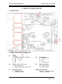
Intelligent Power Supply for Lambda probe
and O2-Probe
NTV44P advance
with terminal
T-300
Date of Issue: 07/2008
MESA Meß- u. Regeltechnik, Roggenstr. 49, D-70794 Filderstadt-Bonlanden
Tel.: 0049 (0)711 / 78 4030, Fax: 0049 (0)711 / 787 40329
NTV44P_manual_1_21_draft_filderstadtadresse21
messen – steuern – automatisieren - messen – steuern – automatisieren - messen – steuern – automatisieren
User Manual
Manufacturer
MESA Electronic GmbH
Leitenstraße 26
D-82538 Geretsried-Gelting
Telephone (0 81 71) 76 93-0
Fax (0 81 71) 76 93-33
Your sales partner
About the contents
The operating manual NTV44P documents structure, measuring
technique, function, and installation of the device as well as error
diagnostics.
The instructions address all users (owners) and operators of the
NTV44P. It must be accessible to these persons and must be read
through carefully before using the device.
All rights to this documentation, especially the right of reproduction and distribution and
translation reserved by MESA Electronic GmbH, and for the event of copyright
applications. No part of the documentation may be reproduced or modified, copied or
distributed using electronic systems in any form without the express permission of MESA
Electronic GmbH.
Subject to errors and technical modifications.
© MESA Electronic GmbH
MESA Electronic GmbH will not be liable for any errors in this documentation. Liability
for any direct or indirect damages caused in connection with the delivery or use of this
documentation is excluded insofar as this is legally permissible
MESA Electronic GmbH P Leitenstrasse 26 P D-82538 Geretsried–Gelting P Tel.: 08171-7693-0 P Fax: 08171-7693-33
E-mail: [email protected] P Homepage: www.mesa-gmbh.com
NTV44P_manual_1_21_draft_filderstadtadresse
NTV44P Operating Manual
MESA Electronic GmbH
TABLE OF CONTENTS
1. INTRODUCTION ......................................................................................................... 4
2. INPUTS AND OUTPUTS ............................................................................................ 6
2.1 Main board .........................................................................................................................6
2.2 Pin assignments of Main board: .......................................................................................6
2.3 Main board LED indication..............................................................................................7
2.4 Upper - CPU board............................................................................................................7
2.5 Pin assignments of CPU board: ........................................................................................7
2.6. Input / output specification ..............................................................................................8
2.6.1 Inputs: ...................................................................................................................... 8
2.6.2 Outputs: ................................................................................................................... 9
2.6.3 Communication connector ....................................................................................... 9
3. SCOPE OF FUNCTIONS ............................................................................................ 9
3.1. L-probe output ..................................................................................................................9
3.2. O2 [%] calculation ............................................................................................................9
3.3. Dew Point calculation .....................................................................................................10
3.4. L-probe - O2 probe computer: .......................................................................................10
4. NTV44P FLUSHING SYSTEM, PARAMETERS AND EXPLANATION ................... 10
5. CORRECTION OF OUTPUT RESULT ..................................................................... 11
6. MENU STRUCTURE WITH TERMINAL T300 .......................................................... 12
7.CONNECTION DIAGRAM ......................................................................................... 14
8.TECHNICAL DATA .................................................................................................... 15
NTV44P Operating Manual
MESA Electronic GmbH
1. INTRODUCTION
The NTV 44P is a unique power supply which allows controlling the working temperature
of L-Probe to a constant value. Thus, error due to cooling by different gases or ambient
temperature changes is completely compensated.
The NTV 44P is available on market in the following Versions:
Basic Version:
L-Probe input
Control of working temperature of L-Probe
Non isolated analogue output 0…1300 mV
Options for Basic Version:
Calculation of O2 % in a customer defined range
Dew Point calculation for fixed process parameters
Time flushing modus with fix flushing cycle time
Isolated universal output module with 0 …1300 mV ; 0 ... 10V;
0 … 20 mA; 4 … 20 mA
Advanced Version:
L-Probe or O2-Probe input
Control of working temperature of L-Probe
Isolated Thermocouple input
Isolated universal output module with 0 …1300 mV ; 0 ... 10V;
0 … 20 mA; 4 … 20 mA
One implemented mathematical function like %O2 or Dew Point or
L-Probe / O2-Probe conversion
Two point correction on above mentioned mathematical function
Four Flushing modes Time flushing, Temperature flushing, mV flushing
and flushing via digital input
Optional you need one T300 Terminal to configuring all mentioned Functions of all your
devices.
Page 4 of 16
NTV44P Operating Manual
MESA Electronic GmbH
Page 5 of 16
NTV44P Operating Manual
MESA Electronic GmbH
2. INPUTS AND OUTPUTS
2.1 Main board
2.2 Pin assignments of Main board:
X1
Supply
1. L ~230V/50Hz or ~115V/50Hz
2. N
3. PE
3. PE
3. PE
X4
Probe heater
8. +Power Sense
9. +12V
10. 0V
11. -Power Sense
Input from probe
12. +Input of probe
13. -Input of probe
X2
Relay - optional for flushing
4. Relay output N.O.
5. Relay output Comm. (fuse 5A F)
X5
X3
Analogue output
6. +Analogue output
7. -Analogue output
P2/X10 Potentiometer
14,15,16, - Optional external
offset potentiometer
Page 6 of 16
NTV44P Operating Manual
MESA Electronic GmbH
2.3 Main board LED indication
- LED D5/D7 (see picture above) indicate that NTV 44P is correct supplied with Power
D5
D7
150V – 180V
OFF
ON
180V – 210V
OFF
OFF
210V – 230V
ON
ON
230V – 250V
ON
OFF
- LED D6 (see picture above) indicates the status of the flushing relay:
Green means flushing contact connector X2 Pin 4/5 is closed
Not green means flushing contact connector X2 Pin 4/5 is open
2.4 Upper - CPU board
2.5
Page 7 of 16
NTV44P Operating Manual
MESA Electronic GmbH
Pin assignments of CPU board:
X6
Digital outputs for O2% range
17. Common Digital output
18. OUT1 Digital output
19. OUT2 Digital output
X7
Digital input
20. 0V Digital input, start flushing
X9
Pressure sensor input
24. 0V – supply for sensor
25. - input from sensor
26. + input from sensor
27. +10V – supply for sensor
X15
T300 terminal connector
21. +24V Digital input, start flushing
X8
Thermocouple K/S input
22. – thermocouple (white/white)
23. +thermocouple (green/orange)
2.6. Input / output specification
2.6.1 Inputs:
- L-Probe Input (X5): from -20 mV… 1300 mV.
- Thermocouple input (X7): type S (PtRh-Pt) or K (NiCr-Ni), cold junction compensation
on board.
- Pressure sensor input (X9): optional - used for compensation of output results.
- Digital Input (X6): Electrically isolated digital input for manual start flushing. Can be
configure to activate by +24V DC or via external switch - short connection between pins.
SW2
SW5
SW6
digital output 1
optocoupler
TTL
output
output
OFF
ON
x
x
OFF
ON
digital output 2
TTL
optocoupler
output
output
x
x
ON
OFF
ON
OFF
Digital input
SW1
SW3
SW4
contact input
+24VDC input
ON
OFF
ON
OFF
ON
OFF
Page 8 of 16
NTV44P Operating Manual
MESA Electronic GmbH
2.6.2 Outputs:
- Universal analog output (X3). Can be chosen by selector switch:
SW1
SW2
SW3
SW4
SW5
0 - 2.5V
ON
OFF
OFF
ON
OFF
0 - 10V
ON
OFF
OFF
ON
ON
0 - 20mA
OFF
ON
ON
OFF
OFF
SW6
not
used
- Two Digital outputs (X6) for indication of current range for auto range O2% output
calculation. If more than one range of O2% is enabled, then program automatically define
current range in which is result and indicate it by those outputs, see 3.2
Can be configured as: open collector (opto isolated) or standard transistor output: low
value is 0.2V and high value is 5V (non opto isolated).
2.6.3 Communication connector
- One standard RS232 interface for connection to Terminal T300 in order to configure
working of NTV44P device, and to get measurement results and device status in digital
way.
3. SCOPE OF FUNCTIONS
NTV44P device can be ordered with possibility to provide one of next calculation:
3.1. L-probe output
Buffered L-probe voltage 0 to 1300 mV. L-probe voltage is electrically isolated and
transfer to standard voltage or current signal according to chapter 2.6.2
3.2. O2 [%] calculation
Due to the wide measurement range of O2 [%], this output values are divided in four
segments, automatic range of segment is provided according to the measurement results.
State of segment position can be seen on two digital outputs (Digital Output 1 & 2) as
binary coded values:
Page 9 of 16
NTV44P Operating Manual
Out2
0
0
1
1
MESA Electronic GmbH
Out1
0
1
0
1
segment 1
segment 2
segment 3
segment 4
During configuration it is necessary to enter the number of segments (1 – without the
change of segments) and the min and the max value for corresponding segments.
Overlapping of max of and min values between segments provide hysteresis of changing
current segment of output. The result value (O2%) can be influenced for arithmetic
adaptation of the measured values to the specific conditions of the respective plant with
two correction values, which are entered via terminal T300.
3.3. Dew Point calculation
With this function Dew Point can be calculated and converted to appropriate analogue
signal to the output in the defined ranges. For this conversion a thermocouple measurement
of temperature is needed. It is also necessarily to specify values for H2% and CO% like
constant through T300 terminal. The result value ( Dew Point) can be influenced for
arithmetic adaptation of the measured values to the specific conditions of the respective
plant with two correction values, which are entered via terminal T300, option 3.8, see
chapter 6.
3.4. L-probe - O2 probe computer:
When used as an L-probe to O2-probe computer the voltage signal of an L-probe is
converted into an equivalent voltage signal of a conventional zirconium dioxide probe. For
this conversion a thermocouple measurement of temperature is needed.
The result signal (O2-probe voltage) can be influenced for arithmetic adaptation of the
measured values to the specific conditions of the respective plant with two correction
values, which are entered via terminal T300.
4. NTV44P FLUSHING SYSTEM, PARAMETERS AND
EXPLANATION
Flushing of probe is activated with the relay inside NTV44P. Origin for start flushing
should be defined inside "NTV Settings" menu of T300 terminal. There can be more than
one origin of start flushing (even all four). Time of flushing is defined also in parameter.
Page 10 of 16
NTV44P Operating Manual
MESA Electronic GmbH
During, and after flushing last value of output voltage is retained. Time after flushing while
output is constant is named "recovery time", and also should be defined as parameter.
Origin of Flushing inside "Flush Config" parameter:
- Time Flushing. Period between two flushing is defined as "Flushing Cycle" in minutes.
Duration of flushing is defined in "Flush Time" parameter in seconds. Recovery time is
defined in parameter "Flush Recover" in seconds also.
- Pushbutton or digital input Flushing. If 24 V are available on Digital output X6,
flushing is performed all the time. After end of input voltage, "Flush Time" and "Flush
Recover" is the same as for previous origin.
- Voltage Flushing. If Voltage of Probe is less than defined in "Flush mV", flushing is
started. Duration of flushing and recovery time is defined apart in "Flush mV time" and
"Flush mV recover"
- Temperature Flushing. All the time while temperature is less than defined in "Flush
Temper" parameter, flushing of probe is performed. There is no additional recover time,
and voltage of probe is not holded.
No matter of current configuration, flushing can be started immediately via
Terminal command.
5. CORRECTION OF OUTPUT RESULT
Automatic two point correction mechanism is provided for all versions of device
output calculations. User should only enter known values of measurement results in one or
two measurement point, using Terminal T300, option 7.1, see next chapter. Device itself
chooses right correction point, and sets measured and correction values. If more than two
correction point is entered, device will manage correction to obtain best results. Via menu
option 7.2 by Terminal T300 , all correction data can be cleared at once.
Page 11 of 16
NTV44P Operating Manual
MESA Electronic GmbH
6. MENU STRUCTURE WITH TERMINAL T300
Screens after reset:
Welcome screen two seconds:
Language Selection:
MESA electronic
NTV44P
T300
v1.0
Language
1: German
2: English
Main Menu:
1:Measurements
2:Errors, Reset
3:NTV Settings
4:Start Flushing
5:T300 Settings
6:NTV Version
7:Correction
Menu structure:
Main Menu:
Main Menu:
1: Measurements
2: Errors, Reset
3: NTV Settings
(Scroll Up/down on Array key)
Can sellect with number,
ENTER - select, 'C' level up
v1.0
Probe Input
1023.4 mV
<enter>
1:Measurements
1:Main Results
2:Non Corr result
3:Probe input
4:Junct.Temp.
(5:Temperature)
Corrected result depend on main function
Main result before correction
Voltage of probe input
Ambient temperature inside NTV44P
Measurement of temperature, if temperature function
is required
2:Errors, Reset
1:Errors T300
2:Errors NTV44P
3:Reset device
Show existing error one per one, until press 'C'
Show existing error one per one, until press 'C'
Perform Reset of NTV44P
3:NTV Settings
Show and edit current value of parameters
Corr. Temp
937 OC
<enter>=Edit
<C>=Exit
Edit of the parameter
start after Pressing
ENTER
1:Configuration
1:Probe
2:Output
(3:TC)
Select input/output configuration and ranges
Select type of input probe, can be L or O2 probe
Select range of outputs according chapter 2.6.2
Type of TC probe S or K if Temperature is measurement
2:L Probe
Parameters of L and O2 probe
Page 12 of 16
NTV44P Operating Manual
MESA Electronic GmbH
1:Value K1
2:Value K2
3:Out Ranges
1:O2mV min
2:O2mV max
or
1:DewPoint min
2:DewPoint max
or
1:O2% No. range
2:O2%min1
3:O2%max1
4:O2%min2
5:O2%max2
6:O2%min3
7:O2%max3
8:O2%min4
9:O2%max4
4:Enable Flush
1:Time Flushing
2:Button Flush.
3:mV Flush
4:Flush_Temper.
(5:Time Flushing)
1:Flush Cycle
2:Flush Time
3:Flush Recover
(6:mV Flushing)
1:Flush mV
2:Flush mV time
3:Flush_mV_recov
(7:Flush_Temper.)
(8:Fix Values)
1:Fix CO%
2:Fix H2%
Values needed for scaling of output signal
Range for L or O2 probe output
Default range is 0mV to 1300mV
Range for Dew point probe output
Default range is -30'C to +30'C
Number of range for O2% calculation, can be 1 to 4
if range is 1, then there is no auto range
All O2% boundaries must be from 10-29% to 21%,
Always for O2%
Always for O2%
Exist if O2% number of range is greater than one
Enabling particular origin of flushing
enable time flushing
enable start flushing by digital input
enable flushing by voltage of probe
enable flushing by temperature measurement result
If Time flushing is enabled
Flush cycle time in min.
Duration of flushing in sec.
Recovery time after flushing in sec.
If mV flushing is enabled
mV of Probe for start flushing
Duration of flushing due to mV in sec.
Recovery time after flushing in sec.
(Temperature in 0C for comparison to start
flushing), if Temperature flushing is enabled
Values needed for Dew Point calculation
Concentration of CO% in working gas
Concentration of H2% in working gas
4:Start Flushing
Start flushing Immediate
5:T300 Settings
1:Language
1:German
2:English
3:Clock
Settings of T300
Choose current language
6:NTV44 Version
1:Company
2:SW-Version
3:Serial No.
4:Product Check
(7:Correction)
1:Correct
2:Clear Corr.
3:Corr .Temp
Read Identification and Version strings of NTV44P
Show and Set time
Present if any correction is possible
Enter Correction of output results
Clear correction of output
Correction of Temperature measurements if need
New O2-Corr.
923.4 mV
<enter>=Edit>
<C>=Exit
Page 13 of 16
NTV44P Operating Manual
MESA Electronic GmbH
7.CONNECTION DIAGRAM
Digital outputs
Digital input
GND
Sensor
supply
Sensor
supply
+24V
-
+
X7
Pressure sensor
input
Termocoupler input
K / S type
X8
20 21
-
+
X9
22 23
24 25
+10V
26
27
GND
NTV44P
X2 4 5
X3 6 7
X4 8 9 10 11
X5 12 13
X10 14 15 16
White -
3
Brown +
3
Brown +
3
Green -
2
Yellow
1
White
N PE PE PE
+
Gray
L-probe input
signal
Power Sense
Black
White
0V
White
Contacts for
Flushing function
normaly open
contact rating
230VAC/5A
+12V
230VAC
50-60Hz
500mA T
Power Sense
L N PE
L-probe output
signal
X1
L
L-sonde
1K
Potentiometer
Option
Page 14 of 16
NTV44P Operating Manual
MESA Electronic GmbH
8.TECHNICAL DATA
Construction:
Macrolon housing for wall mounting
Dimensions / Weight:
160 x 120 x 90 mm / 2.5kg
Protection type:
IP64 according to DIN40050
Connection:
Pluggable terminal blocks
Wire cross section max 2.5mm2
L-probe connection:
1m connection cable with plug and coupler
Input measuring probe:
-20 …1300mV DC
Temperature measuring probe:
-Thermocouple S or K type
Digital output:
-Two optocoupler or TTL, max 10mA per output.
Digital Input:
-Contact or +24V DC digital input for start flushing.
Output supply unit:
Heating voltage for L-probe
- 12 V DC in constant voltage mode
- max 15V DC in temperature mode
Limited current to 2.3A max
Output measuring signal:
- Voltage output 0…1300mV DC or 0 … 10V DC
- Current output 0…20mA or 4…20mA
Operating conditions:
Operating temperature 0°C…+50°C
Page 15 of 16
NTV44P Operating Manual
MESA Electronic GmbH
Storage temperature -10°C…+70°C
5…95% relative humidity, non-condensing
Auxiliary voltage:
- 230 VAC ±10% ; 50…50 Hz or
- 115 VAC ±10% ; 50…50 Hz
Power consumption:
Approx.60VA
Fuse:
Main power – “European” fuse 500mA, slow blow
Flushing relay –“European” fuse 5A, fast blow
Page 16 of 16